US10500784B2 - Additive deposition system and method - Google Patents
Additive deposition system and method Download PDFInfo
- Publication number
- US10500784B2 US10500784B2 US15/001,408 US201615001408A US10500784B2 US 10500784 B2 US10500784 B2 US 10500784B2 US 201615001408 A US201615001408 A US 201615001408A US 10500784 B2 US10500784 B2 US 10500784B2
- Authority
- US
- United States
- Prior art keywords
- substrate
- aerosol
- additive
- charged
- charge
- Prior art date
- Legal status (The legal status is an assumption and is not a legal conclusion. Google has not performed a legal analysis and makes no representation as to the accuracy of the status listed.)
- Expired - Fee Related, expires
Links
- 239000000654 additive Substances 0.000 title claims abstract description 200
- 230000000996 additive effect Effects 0.000 title claims abstract description 200
- 230000008021 deposition Effects 0.000 title claims abstract description 71
- 238000000034 method Methods 0.000 title abstract description 55
- 239000000758 substrate Substances 0.000 claims abstract description 241
- 239000000463 material Substances 0.000 claims abstract description 193
- 239000000443 aerosol Substances 0.000 claims abstract description 141
- 238000007600 charging Methods 0.000 claims abstract description 34
- 230000007935 neutral effect Effects 0.000 claims abstract description 21
- 239000010410 layer Substances 0.000 claims description 92
- 239000002344 surface layer Substances 0.000 claims description 56
- 238000005421 electrostatic potential Methods 0.000 claims description 17
- 239000007788 liquid Substances 0.000 claims description 9
- 229920000642 polymer Polymers 0.000 claims description 4
- 238000004590 computer program Methods 0.000 claims description 2
- 238000005137 deposition process Methods 0.000 abstract description 19
- 239000011159 matrix material Substances 0.000 abstract description 7
- 238000000151 deposition Methods 0.000 description 51
- 230000008569 process Effects 0.000 description 33
- 239000012530 fluid Substances 0.000 description 28
- 238000004519 manufacturing process Methods 0.000 description 18
- 150000002500 ions Chemical class 0.000 description 15
- 238000002360 preparation method Methods 0.000 description 8
- 239000007787 solid Substances 0.000 description 6
- 238000001746 injection moulding Methods 0.000 description 5
- 238000002347 injection Methods 0.000 description 4
- 239000007924 injection Substances 0.000 description 4
- 230000005865 ionizing radiation Effects 0.000 description 3
- 238000000110 selective laser sintering Methods 0.000 description 3
- 229920001169 thermoplastic Polymers 0.000 description 3
- 229920001187 thermosetting polymer Polymers 0.000 description 3
- 230000008901 benefit Effects 0.000 description 2
- 239000002801 charged material Substances 0.000 description 2
- 238000010586 diagram Methods 0.000 description 2
- 230000002401 inhibitory effect Effects 0.000 description 2
- 238000003754 machining Methods 0.000 description 2
- 239000002184 metal Substances 0.000 description 2
- 229910052751 metal Inorganic materials 0.000 description 2
- 239000002245 particle Substances 0.000 description 2
- 238000000926 separation method Methods 0.000 description 2
- 239000012815 thermoplastic material Substances 0.000 description 2
- 239000004416 thermosoftening plastic Substances 0.000 description 2
- 238000005054 agglomeration Methods 0.000 description 1
- 230000002776 aggregation Effects 0.000 description 1
- 238000000889 atomisation Methods 0.000 description 1
- 230000015572 biosynthetic process Effects 0.000 description 1
- 238000010924 continuous production Methods 0.000 description 1
- 230000003247 decreasing effect Effects 0.000 description 1
- 238000007786 electrostatic charging Methods 0.000 description 1
- 230000009881 electrostatic interaction Effects 0.000 description 1
- 238000011049 filling Methods 0.000 description 1
- 238000007730 finishing process Methods 0.000 description 1
- 239000011521 glass Substances 0.000 description 1
- 230000005484 gravity Effects 0.000 description 1
- 238000009499 grossing Methods 0.000 description 1
- 238000010438 heat treatment Methods 0.000 description 1
- 230000003116 impacting effect Effects 0.000 description 1
- 230000003993 interaction Effects 0.000 description 1
- 239000008263 liquid aerosol Substances 0.000 description 1
- 230000008018 melting Effects 0.000 description 1
- 238000002844 melting Methods 0.000 description 1
- 150000002739 metals Chemical class 0.000 description 1
- 230000004048 modification Effects 0.000 description 1
- 238000012986 modification Methods 0.000 description 1
- 238000000465 moulding Methods 0.000 description 1
- 238000006386 neutralization reaction Methods 0.000 description 1
- 230000010076 replication Effects 0.000 description 1
- 230000004044 response Effects 0.000 description 1
- 238000007764 slot die coating Methods 0.000 description 1
- 239000002904 solvent Substances 0.000 description 1
- 239000007921 spray Substances 0.000 description 1
- 230000008719 thickening Effects 0.000 description 1
- 238000011144 upstream manufacturing Methods 0.000 description 1
Images


Classifications
-
- B—PERFORMING OPERATIONS; TRANSPORTING
- B29—WORKING OF PLASTICS; WORKING OF SUBSTANCES IN A PLASTIC STATE IN GENERAL
- B29C—SHAPING OR JOINING OF PLASTICS; SHAPING OF MATERIAL IN A PLASTIC STATE, NOT OTHERWISE PROVIDED FOR; AFTER-TREATMENT OF THE SHAPED PRODUCTS, e.g. REPAIRING
- B29C64/00—Additive manufacturing, i.e. manufacturing of three-dimensional [3D] objects by additive deposition, additive agglomeration or additive layering, e.g. by 3D printing, stereolithography or selective laser sintering
- B29C64/10—Processes of additive manufacturing
- B29C64/106—Processes of additive manufacturing using only liquids or viscous materials, e.g. depositing a continuous bead of viscous material
-
- B—PERFORMING OPERATIONS; TRANSPORTING
- B33—ADDITIVE MANUFACTURING TECHNOLOGY
- B33Y—ADDITIVE MANUFACTURING, i.e. MANUFACTURING OF THREE-DIMENSIONAL [3-D] OBJECTS BY ADDITIVE DEPOSITION, ADDITIVE AGGLOMERATION OR ADDITIVE LAYERING, e.g. BY 3-D PRINTING, STEREOLITHOGRAPHY OR SELECTIVE LASER SINTERING
- B33Y10/00—Processes of additive manufacturing
-
- B—PERFORMING OPERATIONS; TRANSPORTING
- B29—WORKING OF PLASTICS; WORKING OF SUBSTANCES IN A PLASTIC STATE IN GENERAL
- B29C—SHAPING OR JOINING OF PLASTICS; SHAPING OF MATERIAL IN A PLASTIC STATE, NOT OTHERWISE PROVIDED FOR; AFTER-TREATMENT OF THE SHAPED PRODUCTS, e.g. REPAIRING
- B29C64/00—Additive manufacturing, i.e. manufacturing of three-dimensional [3D] objects by additive deposition, additive agglomeration or additive layering, e.g. by 3D printing, stereolithography or selective laser sintering
- B29C64/10—Processes of additive manufacturing
- B29C64/106—Processes of additive manufacturing using only liquids or viscous materials, e.g. depositing a continuous bead of viscous material
- B29C64/112—Processes of additive manufacturing using only liquids or viscous materials, e.g. depositing a continuous bead of viscous material using individual droplets, e.g. from jetting heads
-
- B—PERFORMING OPERATIONS; TRANSPORTING
- B29—WORKING OF PLASTICS; WORKING OF SUBSTANCES IN A PLASTIC STATE IN GENERAL
- B29C—SHAPING OR JOINING OF PLASTICS; SHAPING OF MATERIAL IN A PLASTIC STATE, NOT OTHERWISE PROVIDED FOR; AFTER-TREATMENT OF THE SHAPED PRODUCTS, e.g. REPAIRING
- B29C64/00—Additive manufacturing, i.e. manufacturing of three-dimensional [3D] objects by additive deposition, additive agglomeration or additive layering, e.g. by 3D printing, stereolithography or selective laser sintering
- B29C64/10—Processes of additive manufacturing
- B29C64/106—Processes of additive manufacturing using only liquids or viscous materials, e.g. depositing a continuous bead of viscous material
- B29C64/118—Processes of additive manufacturing using only liquids or viscous materials, e.g. depositing a continuous bead of viscous material using filamentary material being melted, e.g. fused deposition modelling [FDM]
-
- B—PERFORMING OPERATIONS; TRANSPORTING
- B29—WORKING OF PLASTICS; WORKING OF SUBSTANCES IN A PLASTIC STATE IN GENERAL
- B29C—SHAPING OR JOINING OF PLASTICS; SHAPING OF MATERIAL IN A PLASTIC STATE, NOT OTHERWISE PROVIDED FOR; AFTER-TREATMENT OF THE SHAPED PRODUCTS, e.g. REPAIRING
- B29C64/00—Additive manufacturing, i.e. manufacturing of three-dimensional [3D] objects by additive deposition, additive agglomeration or additive layering, e.g. by 3D printing, stereolithography or selective laser sintering
- B29C64/20—Apparatus for additive manufacturing; Details thereof or accessories therefor
- B29C64/205—Means for applying layers
- B29C64/209—Heads; Nozzles
-
- B—PERFORMING OPERATIONS; TRANSPORTING
- B33—ADDITIVE MANUFACTURING TECHNOLOGY
- B33Y—ADDITIVE MANUFACTURING, i.e. MANUFACTURING OF THREE-DIMENSIONAL [3-D] OBJECTS BY ADDITIVE DEPOSITION, ADDITIVE AGGLOMERATION OR ADDITIVE LAYERING, e.g. BY 3-D PRINTING, STEREOLITHOGRAPHY OR SELECTIVE LASER SINTERING
- B33Y30/00—Apparatus for additive manufacturing; Details thereof or accessories therefor
-
- B—PERFORMING OPERATIONS; TRANSPORTING
- B29—WORKING OF PLASTICS; WORKING OF SUBSTANCES IN A PLASTIC STATE IN GENERAL
- B29C—SHAPING OR JOINING OF PLASTICS; SHAPING OF MATERIAL IN A PLASTIC STATE, NOT OTHERWISE PROVIDED FOR; AFTER-TREATMENT OF THE SHAPED PRODUCTS, e.g. REPAIRING
- B29C64/00—Additive manufacturing, i.e. manufacturing of three-dimensional [3D] objects by additive deposition, additive agglomeration or additive layering, e.g. by 3D printing, stereolithography or selective laser sintering
- B29C64/20—Apparatus for additive manufacturing; Details thereof or accessories therefor
- B29C64/245—Platforms or substrates
-
- B—PERFORMING OPERATIONS; TRANSPORTING
- B29—WORKING OF PLASTICS; WORKING OF SUBSTANCES IN A PLASTIC STATE IN GENERAL
- B29C—SHAPING OR JOINING OF PLASTICS; SHAPING OF MATERIAL IN A PLASTIC STATE, NOT OTHERWISE PROVIDED FOR; AFTER-TREATMENT OF THE SHAPED PRODUCTS, e.g. REPAIRING
- B29C64/00—Additive manufacturing, i.e. manufacturing of three-dimensional [3D] objects by additive deposition, additive agglomeration or additive layering, e.g. by 3D printing, stereolithography or selective laser sintering
- B29C64/30—Auxiliary operations or equipment
-
- B—PERFORMING OPERATIONS; TRANSPORTING
- B29—WORKING OF PLASTICS; WORKING OF SUBSTANCES IN A PLASTIC STATE IN GENERAL
- B29K—INDEXING SCHEME ASSOCIATED WITH SUBCLASSES B29B, B29C OR B29D, RELATING TO MOULDING MATERIALS OR TO MATERIALS FOR MOULDS, REINFORCEMENTS, FILLERS OR PREFORMED PARTS, e.g. INSERTS
- B29K2995/00—Properties of moulding materials, reinforcements, fillers, preformed parts or moulds
- B29K2995/0003—Properties of moulding materials, reinforcements, fillers, preformed parts or moulds having particular electrical or magnetic properties, e.g. piezoelectric
Definitions
- Custom manufacturing of parts is a growing industry and has wide ranging applications.
- injection molding machines and other machining techniques were used to create models of objects or to create the objects themselves. More specifically, heated materials like glass, metals, thermoplastics, and other polymers are injected into an injection mold specifically formed in the shape of the desired object. The material is allowed to cool in the mold and take on the shape of the mold to form the object. Injection molds are expensive and time-consuming to create and changes to the shape of the object are difficult to accommodate without further increasing the time and expense of creating the object.
- CNC computer numerical control
- the manufacturing industry would benefit from a manufacturing process that realizes the advantages of digital, additive manufacturing with a broad set of thermoplastic materials and feature resolution to be capable of manufacturing objects with the complexity and structural integrity obtained using more traditional manufacturing techniques.
- a system and method of additive deposition that is capable of using a variety of additive materials and depositing them in a high resolution manner across a substrate.
- the system is further capable of creating a matrix of additive material by repeated additive material processes.
- FIG. 1 is an example additive deposition process according to an embodiment of the invention.
- FIG. 2 is a further example additive deposition process according to an embodiment of the invention.
- FIG. 3 is a block diagram of an example additive deposition system according to an embodiment of the invention.
- FIG. 4 is an example additive material preparation portion of an example additive deposition system according to an embodiment of the invention.
- FIG. 5 is an example substrate portion of an example additive deposition system according to an embodiment of the invention.
- FIG. 1 is an example additive deposition process 100 according to an embodiment of the invention.
- the process selectively deposits aerosolized, liquid additive material onto a substrate using a charge potential difference between the aerosol droplets and selected portions of the substrate layer surface.
- the additive material can be a liquid or a liquid form of a material, such as a sold material melted into a liquid state.
- the additive material can be any number of materials, including polymers such as a thermoplastic.
- the material is first made into an aerosol that can be formed in the selective deposition process.
- the selective deposition of additive material onto the substrate layer surface results in a highly efficient process as any excess deposition of additive material is substantially limited as undeposited additive material can be recirculated and recycled back into the process 100 .
- the process 100 has a resolution, or fineness, associated with the deposition based on the resolution of the selectively removed charges. This allows the additive process 100 to achieve high resolution levels based on the charge density and the resolution of a charge altering portion of the process. Repeated depositions of additive materials can be used to create a three-dimensional matrix or object constructed of additive material.
- a liquid aerosol of additive material can be generated in various ways.
- the aerosol is generated 102 using a filament extension atomizer.
- the filament extension atomizer uses a pair of counter-rotating rollers to stretch filaments of liquid fluidized additive material between diverging surfaces of the rollers on a downstream side to generate the aerosol.
- the additive material can be a thermoplastic polymer that is made liquid by heating and melting the polymer.
- the liquid additive material pools on an upstream side of a nip, the space between the pair of rollers, and is drawn into the nip as the rollers counter-rotate.
- the fluid is stretched into a filament between diverging surfaces of the rollers, to which a portion of the fluid still adheres.
- the filament grows longer and thinner.
- the capillary break-up point of the fluid filament the filament breaks into multiple drops.
- the rollers counter-rotate, continuous formation and break-up of fluid filaments across the surface of the rollers generates the aerosol of additive material droplets.
- the aerosol of additive material is then directed to further portions of the process for deposition onto the substrate.
- Other filament extension atomizers can be used including diverging piston, co-rotating rollers, and roller and belt configurations.
- the formed plurality of droplets can be selectively filtered 104 based on size or other physical parameters of the droplets.
- Selectable physical parameters of the plurality of droplets can include droplet size and/or weight.
- a screen filter can be used to select the droplets matching the desired physical parameters.
- an inertial impactor or other devices or methods can be used to select droplets matching desired physical parameters.
- the aerosol of additive material droplets is electrostatically charged 106 to a first polarity in preparation for deposition onto a substrate layer surface.
- An aerosol charger can be used to charge the aerosol droplets as they are transported through or by the charger.
- the aerosol can be charged electrostatically by passing the aerosol through a region in which a corona is contained, an ion current is flowing, or using ionizing radiation which excites electron emission from the droplets, or by other means.
- the substrate layer surface can also undergo a uniform charging process 110 before selectively altering the charge of the substrate layer surface 112 .
- the substrate charging process 110 uniformly electrostatically charges the surface of the substrate layer. That is, the surface of the substrate layer is uniformly charged to a desired charge density with a polarity that can be opposite or the same as that of the charged aerosol.
- a substrate charging apparatus can be used to electrostatically charge the substrate layer surface. Such an apparatus can include a corotron, a scorotron or other coronal discharge device. A coronal discharge device generates a discharge of ions, which uniformly electrostatically charge the substrate layer surface.
- a portion of the surface charge on the substrate can be selectively altered to a substantially neutral state.
- the selective altering of the substrate layer surface charge creates substantially neutral portions of the substrate layer surface to which the charged aerosol is not attracted, or deposited by an electrostatic force. That is, the charged aerosol is selectively deposited by electrostatic force only on those portions of the substrate that remain charged.
- the electrostatic potential causes and electrostatic force that attracts, or deposits, the charged aerosol onto the oppositely charged portions of the substrate layer surface.
- Charged aerosol is continually attracted, or deposited, onto the substrate layer surface until the electrostatic potential between the charged aerosol and charged substrate layer surface is decreased to a critical point. Once the electrostatic potential between the charged aerosol and the substrate surface layer is weakened to a critical point, the electrostatic force is weakened so that substantially no additional charged aerosol is attracted onto the charged substrate surface layer.
- the magnitude of the electrostatic potential, and the strength of the electrostatic force, between the charged aerosol and charged substrate surface layer is based on the charge density and the distance separating the charged aerosol from the charged substrate surface layer. Altering the charge density of the substrate surface layer alters the amount of deposited additive material onto the substrate layer surface. As the charged material is deposited, or attracted, the electrostatic potential between the charged aerosol and the substrate layer surface is reduced as the substrate layer surface charge is neutralized by the deposited charged additive material. Not only can the regions in which the additive material is selectively deposited be limited by selectively altering the electrostatic charge of the substrate layer surface, so can the amount of additive material deposited also be limited similarly. Selectively reducing the electrostatic charge of similarly charged portions or regions of the substrate surface layer causes less similarly charged additive material to be deposited in those portions.
- An ionographic print head or other ion deposition device, can be used to selectively alter the charge of the substrate layer surface 112 .
- the ionographic print head emits ions directed towards the substrate layer surface.
- the emitted ions contact the substrate layer surface and can neutralize or induce an electrostatic charge on the substrate layer surface, depending on the polarity of the discharged ions and the polarity, or electrostatic state, of the substrate layer surface.
- the substrate can be uniformly charged to a second polarity and the discharged ions can have an opposite polarity to that of the substrate layer surface.
- oppositely charged ions contact the substrate layer surface, they neutralize the electrostatic charge of the substrate layer surface at the location of contact.
- the charged areas are selectively altered since the charges of the uniformly charged substrate surface layer were selectively substantially neutralized, or selectively altered to an opposite polarity.
- Charged additive material is deposited, or attracted, onto the charged portions of the substrate surface layer by the electrostatic potential between the substrate surface layer having a second polarity and the charged aerosol having a first polarity.
- the first and second polarity can be the same, in which case the uniformly charged substrate layer surface will repel the charged aerosol, inhibiting deposition. Or, the first and second polarities can be opposite, in which case the uniformly charged substrate layer surface will attract the charged aerosol, resulting in additive material being deposited onto the substrate layer surface.
- the ionographic print head is essentially creating the negative space, the area in which the additive material will not be selectively deposited, or the positive space, the area in which the additive material will be selectively deposited based on the first polarity of the charged aerosol and the second polarity of the uniformly charged substrate.
- the ionographic print head selectively traces an inputted pattern that can be negative or positive.
- Alternative methods and devices can be used to selectively remove the charges from portions of the uniformly charged substrate to facilitate the selective deposition of additive material across the substrate.
- the substrate layer surface can be substantially neutral and the substrate charging apparatus can selectively alter, or charge, the substrate surface layer in desired area(s).
- a substrate charging apparatus can apply charge to targeted areas of the substrate according to a predetermined pattern or input.
- the targeted areas of the substrate that are charged correspond to the areas to which the oppositely charged additive material is attracted.
- the desired pattern is formed on the substrate as a positive image, that is, the formed charged areas of the substrate form the desired pattern or arrangement based on the input.
- the charged aerosol will be repelled by the like electrostatic charges and the additive material will deposit onto regions of the substrate surface in which the electrostatic charge has been selectively altered to an opposite polarity or substantially neutral state.
- the charged aerosol will be attracted and deposited onto the surface due to an electrostatic force caused by the electrostatic potential between the charged aerosol and the oppositely charged substrate surface.
- Selectively altering the charge of the substrate surface to a polarity that is the same as the aerosol will result in the charged aerosol being repelled and inhibited from depositing into these charge altered areas.
- the substrate layer surface charge can be selectively altered to a neutral, or substantially neutral, state.
- the charged aerosol will be attracted and deposited onto the non-altered charged areas of the substrate surface, due to the electrostatic force, but will not be attracted to the substantially neutral portions of the substrate surface.
- Charged aerosol may deposit in the substantially neutral portions, but the deposition will be minimal as the charged aerosol will be strongly attracted to the non-altered, oppositely charged regions.
- the charged aerosol is composed of additive material that is then deposited across the substrate in a desired pattern or arrangement according to the arrangement of the charge altered portions of the substrate.
- the altered charged portions of substrate surface layer drive the deposition and configuration of the charged additive material to form a desired shape, contour, or pattern. This process of depositing layers of charged additive material can be repeated to form a multi-layer, three-dimensional object of additive material.
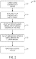
- FIG. 2 is a further example additive deposition process 200 according to an embodiment of the invention.
- the charged aerosol of additive material is deposited onto the substrate layer surface in a similar manner as the previous embodiment of FIG. 1 with the addition of support material that is deposited 208 in gaps or regions between and around the deposited additive material.
- the next layer can be built on a substantially planar surface in order to facilitate more even electrostatic charging.
- Depositing support material around the additive material provides this and the support for future layers as they are formed.
- the support material does not interact with additive material and the two materials are easily separated once the additive deposition process is complete and the desired object, or matrix, formed of additive material is complete.
- Each resultant layer of additive and support material forms the substrate layer for the next additive process.
- the new substrate layer surface is processed as outlined herein to form the next layer of additive and support material, with the process repeating until the object is formed.
- the support material can be a number of materials, including fluids and solids, which are selected based on their characteristics and interactions with the additive material.
- the support material is deposited around the selectively deposited additive material and may be leveled to form a new substrate layer on which the next additive deposition process will occur.
- the support material can be a fluid that is dispensed across the selectively deposited additive material and the substrate layer surface.
- the fluid does not bond or is easily separable from the selectively deposited additive material.
- the fluid can harden to solid or semi-solid state to support the selectively deposited additive material.
- the fluid can be evenly spread and leveled about the additive material using a doctor blade set at a fixed or variable height from the substrate layer surface. Additionally, during the support material process, the doctor blade can be used to remove excess, or built-up, additive material, ensuring an even and level layer for the next additive deposition process.
- a slot die coating method and device can be used, as can an inkjet process that dispenses the support material in between the regions of the selectively deposited additive material. Additional alternative methods and devices can be used to add support material in the regions between the selectively deposited additive materials.
- At least a portion of the substrate surface layer can be uniformly charged 202 .
- a blanket charging apparatus such as a scorotron, that evenly charges the substrate surface layer to a second polarity opposite that of the first polarity of the additive material aerosol.
- a portion of the substrate surface layer charge is selectively altered 204 in a selected pattern or arrangement.
- the selectively charge altered portions become substantially neutral or oppositely charged, i.e. altered from the second polarity to the first polarity.
- the charge unaltered portions of the substrate surface layer are the portions to which the charged aerosol of additive material will be electrostatically attracted and deposited onto by an electrostatic force.
- the charge altered regions, or substantially neutral regions, will not have additive material deposited thereon as the charged aerosol will be repelled from depositing and/or the electrostatic force will be weak enough to not attract charged aerosol droplets onto the substrate surface layer for deposition.
- a substantially neutral substrate surface layer can be selectively electrostatically altered to a polarity opposite the first polarity of the electrostatically charged aerosol of additive material.
- the charged aerosol is then selectively deposited on the portions of the substrate surface layer that have been selectively electrostatically altered and are not attracted to the neutral portions of the substrate surface layer where no electrostatic charge has been applied.
- a portion of the charged aerosol of additive material is then deposited 206 on the charged portions of the substrate surface layer formed by selectively altering the electrostatic charge(s) of the said layer.
- the substrate surface layer now has a selectively deposited layer of additive material deposited onto it. Gaps are formed on the substrate between and around the deposited additive material. The gaps are regions where the electrostatic charge of the substrate surface layer was selectively removed or was never applied, which inhibited the deposition of additive material onto those portions of the substrate. The gaps are voids between the deposited additive material and vary in size, shape, and contour in opposing compliment to the deposited additive material.
- the gaps are then filled 208 with a support material, as described above.
- the support material can be a number of different materials, including a liquid or a solid that is dispensed and leveled around and between the deposited additive material as described above.
- the support material surrounds and supports the selectively deposited additive material structure as it is formed in a layer-by-layer process.
- the support material can be a thermoset material.
- the thermoset material is a malleable prepolymer that can be pressed into the gaps between the deposited additive materials using the doctor blade. Once deposited in the gaps, the thermoset support material is cured, or heated, to polymerize and set the material into a solid, hard material that surrounds and supports the selectively deposited additive material.
- this process 200 can be repeated 210 to create a multi-layer, three-dimensional structure that is formed in a layer-by-layer process using a substrate charge deposition and selective charge removal and/or selective charge application process.
- each portion of the process can be completed across at least a portion of the substrate before moving onto the next portion of the process, or the various steps of the processes can occur simultaneously in the orders outlined as the substrate is translated through the various portions of the system.
- FIG. 5 shows an additive deposition process in which the latter occurs, whereby the various process steps are done concurrently as the substrate is translated through the various portions.
- an example additive deposition system 300 includes an additive material handling portion 301 and a substrate handling portion 311 that intersect when the charged aerosol of additive material 308 is deposited onto the substrate 318 .
- the material handling portion 301 includes a passage of channel(s) through which the charged additive material is directed over the selectively charged translating substrate. An opening in the passage or channel allows the charged additive material to be pulled through by an electrostatic force and deposited onto areas of the substrate surface layer due to the electrostatic potential between the charged aerosol and selected regions of the substrate surface layer. Un-deposited material, charged additive material that was not attracted to selected portions of the substrate surface layer, can be re-circulated or recycled back into the additive material handling portion 301 .
- a filament extension atomizer 302 is included in the additive material handling portion 301 of the system 300 .
- the filament extension atomizer 302 is used to generate the aerosol of additive material to be deposited onto the substrate surface layer 312 .
- the filament extension atomizer 302 uses a pair of counter-rotating rollers to stretch fluid filaments of additive materials between diverging surfaces of the rollers on a downstream side. The filaments are stretched to a capillary break-up point, at which point a portion of each of the fluid filaments breaks down into as an aerosol of additive material droplets.
- Non-Newtonian fluids can be difficult to atomize due to extensional thickening that occurs in stretched filaments of the fluid, which requires the filaments to be stretched beyond the ability of conventional spray generators, to generate the aerosol of atomized fluid material.
- the fluid extension atomizer can also be used with a Newtonian fluid to create an aerosol.
- the aerosol can then be filtered based on size or other physical parameters of the droplets by an aerosol size selection apparatus or method 304 .
- Size, or other physical parameter, selection 304 of the generated aerosol can be done by a filter, inertial impactor or other device or method capable of excluding droplets having physical parameters outside of predetermined limits.
- the inertial impactor is placed in the stream of aerosol droplets and includes geometry, such as sharp corners, that requires the droplets to flow around to continue downstream. Droplets having a momentum that exceeds a threshold set by the geometry of the impactor are excluded from the stream, instead impacting the geometry of the impactor rather than flowing around. Momentum of a droplet is a function of speed and mass of the droplet, allowing the impactor to exclude droplets that are outside of predetermined size and weight parameters.
- the aerosol is charged 306 in preparation for deposition on the substrate 312 .
- the aerosol is charged 306 by an aerosol charging apparatus.
- the aerosol charging apparatus can generate a region in which a corona is contained, an ion current is flowing, or ionizing radiation which excites electron emission from the droplets, charging the droplets of the aerosol to a desired first polarity.
- the charge of the aerosol can be opposite in polarity to the blanket charge of the substrate surface layer 312 , which causes the charged aerosol to be attracted to the oppositely charged portions of the substrate surface layer.
- the aerosol 308 is guided, or passed, parallel over the surface of the selectively charged substrate surface layer 318 to deposit the additive material.
- the oppositely charged aerosol and portions of the substrate surface layer are attracted to one another due to an electrostatic potential.
- the electrostatic potential creates an electrostatic force which drives the aerosol to deposit onto the selected regions of the substrate surface layer.
- the charged aerosol of additive material can be guided through a passage or channel by an airstream or other method.
- An opening on the passage or channel allows charged aerosol droplets to electrostatically interact with the selected portions of the substrate surface layer only over a defined region, creating the electrostatic potential and resultant electrostatic force between the two.
- the electrostatic force causes a portion of the charged aerosol of additive material to exit the passage or channel through the opening and selectively deposit onto the substrate surface layer.
- Un-deposited charged aerosol can be optionally recycled 310 back into the filament extension atomizer 302 for use in later additive deposition processes. In this manner, substantially only the additive material deposited onto the substrate is used, which results in a high efficiency additive process. The excess, un-deposited additive material is redirected back through the additive material handling portion 301 to the filament extension atomizer. The fluid additive material can then undergo further aerosol generation processes.
- the substrate handling portion 311 of the additive deposition system 300 can uniformly charge and selectively alter electrostatic charges of the substrate surface layer 312 to facilitate the selective deposition of additive material.
- the substrate surface layer 312 can be initially blanketed with a uniform charge 314 of a similar or opposite polarity to that of the first polarity of the charged aerosol 308 .
- a blanket charging apparatus is used charge the substrate surface layer 312 .
- At least a portion of the charge is selectively altered 316 .
- An ionographic print head or other suitable device or apparatus can be used to selectively alter the electrostatic charge of the substrate surface layer. Selectively altering the charge of the substrate surface layer creates areas of the surface that are charge neutral, similarly charged to the first polarity or oppositely charged to the first polarity. The neutral, or similarly charged portions of the substrate surface layer do not attract the charged aerosol, inhibiting or preventing the deposition of additive material in these locations.
- the substrate is translated 318 past the charged aerosol guiding structure.
- the charged aerosol droplets are selectively deposited onto the substrate surface layer by an electrostatic force caused by the electrostatic potential between the charged aerosol and selected regions of the substrate surface layer. Once deposited, the additive material is allowed to cool and solidify.
- the substrate can also undergo further additive deposition step(s).
- Support material can be applied 320 between the deposited additive materials to create a new, level substrate layer surface.
- the support material can be dispensed across the current substrate surface layer and leveled about the selectively deposited additive material to form a new substrate layer surface for the next additive deposition process.
- the result is a smooth, continuous layer of additive material and support material forming a substrate layer surface, the entire structure of additive material and additive material supported by the original substrate.
- the previous layer of selectively deposited additive material can be kept in a semi-fluid state to assist with adhering and bonding the next additive material layer to form the multi-layer structure.
- the whole process can be completed in a heated environment, so that each successive selective deposition of additive material bonds to the previously deposited material.
- any residual charges of the deposited additive material and/or substrate surface layer can be neutralized 322 concurrently during the scorotron pre-charge step.
- the neutralization of any residual charges can be done as a separate step before the scorotron pre-charge step.
- the surface now once more travels through the substrate handling portion 311 of the additive deposition system 300 . This process can be repeated as many times as necessary to create a structure or matrix of selectively applied additive material.
- the substrate translation 318 can include moving the substrate in a vertical axis, thereby maintaining a constant and fixed separation between the charged aerosol deposition and the substrate layer surface.
- the charged aerosol deposition can be translated vertically to maintain the same separation.
- FIG. 4 is an example additive material preparation portion 401 of an additive deposition system 400 according to an embodiment of the invention.
- an aerosol 406 of additive material is formed using a filament extension atomizer 402 .
- the additive material aerosol is charged 422 in preparation for deposition through an opening 430 onto a substrate.
- Additive material, in a fluid form is introduced, either externally or internally, to the filament extension atomizer 402 .
- a pair of counter-rotating rollers 404 engage the fluid additive material, and stretch filaments of additive material between the diverging downstream surfaces of the rollers 404 . As the fluid filaments are stretched between the rollers 404 , the fluid filament reaches a point of instability, a capillary break-up point.
- each of the fluid filaments breaks down into an aerosol of additive fluid droplets 406 .
- An introduced airstream 408 can be used to guide the formed aerosol through the additive material preparation portion 401 of the system 400 .
- the air stream 408 can be created by the rotation of the rollers 404 of the filament extension atomizer 402 or by other means, such as an external source.
- the aerosol 406 formed by the filament extension atomizer 402 can be filtered based on droplet size and/or weight.
- the force of gravity on the droplets of the formed aerosol 406 can be used to prevent oversized and/or overweight droplets from proceeding further through the portion 401 .
- Varying the vertical height of the filament extension atomizer 402 with respect to the airstream 408 can be used to selectively allow droplets of a desired size and/or weight to exit the filament extension atomizer 403 and continue through the portion 401 and into the passage 410 .
- a passage 410 guides the generated aerosol from the filament extension atomizer 402 through the additive material handling portion 401 of the system 400 .
- the passage 410 is positioned to guide the flow of the generated aerosol parallel and proximate to the translating substrate to facilitate the deposition of charged additive material onto selected portions of the substrate surface layer based on the electrostatic interaction between the charged aerosol and the selectively charge altered substrate surface layer.
- a droplet selector 412 can be disposed within a passage 410 of the additive material handling portion 401 .
- the droplet selector 412 can selectively remove, or exclude, droplets that have physical parameters, such as size and weight, outside a set of desired parameters. Excluded droplets can be recycled 414 back into the filament extension atomizer 402 for later use.
- the droplet selector 412 is an inertial impactor that is positioned in the stream of flowing formed aerosol.
- the impactor includes geometry to selectively filter aerosol droplets based on their momentum. Using this geometry, droplets that are outside of a predetermined and/or desired physical parameter range are blocked from continuing through the passage 410 .
- An aerosol charging apparatus 420 electrostatically charges the aerosol droplets as they pass.
- the charging apparatus 420 induces an electrostatic charge in the aerosol droplets in preparation for deposition onto a substrate surface layer.
- the charging apparatus 420 can generate a region in which a corona is contained, an ion current is flowing, or ionizing radiation through which the aerosol droplets are passed. This excites electron emission from the droplets to electrostatically charge them to a desired polarity.
- Charged aerosol droplets 422 continue through the passage 410 and across a deposition opening 430 .
- the charged aerosol 422 passes across the deposition opening 430 , a portion of the charged aerosol is attracted and deposited through the opening 430 onto a substrate surface layer passing below due to an electrostatic force caused by the electrostatic potential between the charged aerosol 422 and the substrate surface layer.
- the excess, or residual, charged aerosol 422 that continues through the passage can be recycled 414 back into the system 400 .
- FIG. 5 illustrates an example substrate portion 501 of the additive deposition system 400 .
- a substrate 502 can be uniformly blanket charged before a portion of the charge of the substrate 502 layer surface is selectively altered.
- charged aerosol droplets 422 are attracted and deposited onto selected regions of the substrate 502 layer surface due to an electrostatic force caused by the electrostatic potential between the substrate 502 layer surface and charged aerosol 422 .
- the electrostatic force drives a portion of the charged aerosol 422 from the deposition passage opening 430 onto selected regions of the substrate 502 layer surface. Remaining charged aerosol continues through the deposition passage 410 to be recycled or disposed of.
- the charged aerosol 422 is attracted to the oppositely charged portions of the surface of the substrate. Gaps 514 form between the deposited portions of additive material 423 that are filled with a support material 530 to create a smooth, continuous layer of material, support and additive, that covers the substrate layer surface.
- the electrostatic charges are then substantially neutralized from the substrate and additive material to create a new electrostatically neutral substrate layer surface that can be fed through the additive deposition system 400 for further additive material deposition processes.
- the substrate 502 is translated through the system 400 by a substrate translation system 506 .
- a uniform blanket electrostatic charge can be induced across the substrate 502 layer surface by a blanket charging apparatus 504 .
- the substrate is blanketed with a negative charge.
- a scorotron can be used to create the blanket charge across the substrate layer surface.
- the scorotron electrostatically charges the substrate layer surface by generating a corona discharge and accelerates the charge toward the passing substrate, charging the substrate surface layer until the surface charge density causes the surface potential to be equal to that of the scorotron grid.
- the corona discharge can be formed by placing a high voltage on a thin wire inside a metal walled cylinder. The high field thus created in turn ionizes the surrounding gas, such as air.
- the substrate layer surface As the substrate passes through the formed cloud of charged particles, the substrate layer surface is charged to a polarity of that of the emitted particles.
- the scorotron allows the substrate layer surface to be charged to uniform charge density regardless of previous charge states, which can eliminate the need to reduce or substantially neutralize residual charges of the new substrate layer surface, of support and additive material, before a further additive deposition process occurs.
- the selective charging apparatus 510 is an ionographic print head.
- the ionographic print head directs (or accelerates using a grid) a stream of ions having a polarity opposite that of the charged substrate. The emitted oppositely charged ions neutralize or oppositely charge a local region of the substrate layer surface.
- the ionographic print head can neutralize, oppositely charge or charge in a selective manner based on an input such as a pattern, computer control instructions or others.
- the ionographic print head 510 can be moved across the surface of the substrate 502 in a linear manner perpendicular to the translation of the substrate 502 , with the substrate 502 advancing a width of the ionographic print head 510 after each pass.
- the linear motion of the ionographic print head 510 in combination with the translation of the substrate 502 , form a 2-dimensional pattern of selectively charged portions across the surface of the substrate 502 .
- an array of ionographic print heads or other ion deposition device can be arranged. In this manner, the amount of substrate 502 layer surface covered by each pass of the array can be increased. Or, the array can span a distance equal or greater than the width of the substrate 502 which would allow the array to be fixed, with the substrate 502 advancing underneath, either in a continuous or step-wise manner.
- the substrate 502 is translated below the deposition opening 430 by the substrate translation system 506 .
- the charged aerosol 422 flows through the passage 412 and across the deposition opening 430 , a portion of the charged aerosol 422 is attracted onto the oppositely charged regions 512 of the substrate 502 layer surface.
- the oppositely charged portions 512 of the substrate 502 layer surface are those portions of the substrate 502 layer surface where the blanket charge has not been selectively removed or oppositely charged.
- the portions of the surface of the substrate 502 where the charge was selectively altered to a neutral or oppositely charged state form gaps 514 between the selectively deposited, charged additive material 423 .
- a support material 530 is deposited across the substrate 502 layer surface and deposited additive material 422 , filling the gaps 514 .
- a doctor blade 534 is positioned a set distance off the surface of the substrate 502 , smoothing and leveling the surface of the selectively deposited additive material 422 and support material 530 .
- the substrate 502 can undergo repeated additive material deposition processes or the additive material can be allowed to set, if necessary, to the substrate, as discussed above.
- the support material 530 can be bonded to the substrate 502 as part of the setting process, or can be removed, leaving the set deposited additive material object.
- the substrate translation system 506 can translate the substrate horizontally in the plane of the substrate 502 and vertically, perpendicular to the substrate 502 .
- the substrate 502 can be translated by the system 506 along three axes.
- the substrate translation system 506 can translate the substrate 502 in an incremental, or step-wise, manner after each pass of the selective charging apparatus 510 .
- the substrate translation can translate the substrate 502 in a vertical axis before repeating the translation in a horizontal plan to create a new layer of selectively deposited additive material.
- the substrate 502 can be translated in 2 or more axes to complete the desired charge removal pattern.
- the various components of the substrate portion 501 of the additive deposition system 400 can be arranged so that the substrate 502 is translated under the components 504 , 510 and 530 in sequence. In this manner, the substrate 502 can be continuously processed through the system 400 .
- Repeating the additive material deposition process through the system 400 can be used to build up the additive material in a 3-dimensional matrix of material.
- the repeated additive material deposition processes create a high-resolution 3-dimensional object.
- the resolution of the additive deposition process can be varied based on the fineness and accuracy of the selective charge removal apparatus 510 .
- the resolution is further enhanced due to the selective thickness of the deposited additive material.
- a greater electrostatic potential between the charged aerosol 422 and the oppositely charged substrate 502 can result in a larger agglomeration of aerosolized additive material on the substrate 502 , as additional charged aerosol can be required to neutralize the oppositely charged region of the substrate layer surface depending on the magnitude of the electrostatic potential.
- the support material 530 can be removed in a finishing process to expose the solid 3-dimensional object formed of deposited additive material.
Landscapes
- Chemical & Material Sciences (AREA)
- Engineering & Computer Science (AREA)
- Materials Engineering (AREA)
- Manufacturing & Machinery (AREA)
- Optics & Photonics (AREA)
- Mechanical Engineering (AREA)
- Physics & Mathematics (AREA)
- Application Of Or Painting With Fluid Materials (AREA)
- Electrostatic Spraying Apparatus (AREA)
- Health & Medical Sciences (AREA)
- General Health & Medical Sciences (AREA)
- Toxicology (AREA)
- Organic Chemistry (AREA)
- Chemical Kinetics & Catalysis (AREA)
Priority Applications (6)
| Application Number | Priority Date | Filing Date | Title |
|---|---|---|---|
| US15/001,408 US10500784B2 (en) | 2016-01-20 | 2016-01-20 | Additive deposition system and method |
| TW106100332A TWI707769B (zh) | 2016-01-20 | 2017-01-05 | 積層沈積系統 |
| CN201710020713.8A CN106985378B (zh) | 2016-01-20 | 2017-01-11 | 增材沉积系统和方法 |
| KR1020170004043A KR102481039B1 (ko) | 2016-01-20 | 2017-01-11 | 첨가제 증착 시스템 및 방법 |
| EP17151223.9A EP3196002B1 (en) | 2016-01-20 | 2017-01-12 | Additive deposition system |
| JP2017003656A JP6749849B2 (ja) | 2016-01-20 | 2017-01-12 | 付加堆積システムおよび方法 |
Applications Claiming Priority (1)
| Application Number | Priority Date | Filing Date | Title |
|---|---|---|---|
| US15/001,408 US10500784B2 (en) | 2016-01-20 | 2016-01-20 | Additive deposition system and method |
Publications (2)
| Publication Number | Publication Date |
|---|---|
| US20170203504A1 US20170203504A1 (en) | 2017-07-20 |
| US10500784B2 true US10500784B2 (en) | 2019-12-10 |
Family
ID=57796214
Family Applications (1)
| Application Number | Title | Priority Date | Filing Date |
|---|---|---|---|
| US15/001,408 Expired - Fee Related US10500784B2 (en) | 2016-01-20 | 2016-01-20 | Additive deposition system and method |
Country Status (6)
| Country | Link |
|---|---|
| US (1) | US10500784B2 (zh) |
| EP (1) | EP3196002B1 (zh) |
| JP (1) | JP6749849B2 (zh) |
| KR (1) | KR102481039B1 (zh) |
| CN (1) | CN106985378B (zh) |
| TW (1) | TWI707769B (zh) |
Cited By (2)
| Publication number | Priority date | Publication date | Assignee | Title |
|---|---|---|---|---|
| US20190061233A1 (en) * | 2017-08-22 | 2019-02-28 | Palo Alto Research Center Incorporated | Electrostatic polymer aerosol deposition and fusing of solid particles for three-dimensional printing |
| US20220380928A1 (en) * | 2021-05-29 | 2022-12-01 | Nissan North America, Inc. | Method and system of powder coating a vehicle component |
Families Citing this family (7)
| Publication number | Priority date | Publication date | Assignee | Title |
|---|---|---|---|---|
| US9757747B2 (en) | 2014-05-27 | 2017-09-12 | Palo Alto Research Center Incorporated | Methods and systems for creating aerosols |
| US10493483B2 (en) | 2017-07-17 | 2019-12-03 | Palo Alto Research Center Incorporated | Central fed roller for filament extension atomizer |
| US11724448B2 (en) * | 2017-07-17 | 2023-08-15 | Hewlett-Packard Development Company, L.P. | Disguising color in 3D object formation |
| US10464094B2 (en) | 2017-07-31 | 2019-11-05 | Palo Alto Research Center Incorporated | Pressure induced surface wetting for enhanced spreading and controlled filament size |
| US10786946B2 (en) * | 2017-09-13 | 2020-09-29 | Thermwood Corporation | Apparatus and methods for compressing material during additive manufacturing |
| DE102018107585B3 (de) * | 2018-03-29 | 2019-03-28 | Universität Rostock | Vorrichtung zur Herstellung von 3D-gedruckten Wirkstofffreisetzungssystemen mit Wirkstoffdepots, sowie Verfahren zur Herstellung von 3D-gedruckten Wirkstofffreisetzungssystemen |
| US11909052B2 (en) | 2021-06-30 | 2024-02-20 | Xerox Corporation | Fabrication of membrane electrode assembly with filament extension atomizer spray |
Citations (74)
| Publication number | Priority date | Publication date | Assignee | Title |
|---|---|---|---|---|
| US2291046A (en) | 1942-07-28 | Arrangement for burning liquid fuel | ||
| US2551582A (en) * | 1943-08-27 | 1951-05-08 | Chester F Carlson | Method of printing and developing solvent images |
| FR1035235A (fr) | 1951-04-09 | 1953-08-19 | Rodanet & Cie Ets | Perfectionnements aux rouleaux à peindre, à alimentation automatique et à main |
| US3052213A (en) | 1958-12-17 | 1962-09-04 | Ibm | Electrostatic printer apparatus for printing with liquid ink |
| US3068115A (en) | 1961-02-06 | 1962-12-11 | Xerox Corp | Electrostatic emulsion development |
| US3330683A (en) | 1961-04-26 | 1967-07-11 | Bayer Ag | Method of developing an electrostatic image with an electrically charged liquid aerosol |
| US3554815A (en) | 1963-04-30 | 1971-01-12 | Du Pont | Thin,flexible thermoelectric device |
| US3626833A (en) | 1969-06-09 | 1971-12-14 | Addressograph Multigraph | Liquid developing apparatus |
| US3649829A (en) | 1970-10-06 | 1972-03-14 | Atomic Energy Commission | Laminar flow cell |
| US3702258A (en) | 1969-03-05 | 1972-11-07 | Eastman Kodak Co | Web treatment method |
| US3717875A (en) | 1971-05-04 | 1973-02-20 | Little Inc A | Method and apparatus for directing the flow of liquid droplets in a stream and instruments incorporating the same |
| US3779166A (en) | 1970-12-28 | 1973-12-18 | Electroprint Inc | Electrostatic printing system and method using ions and toner particles |
| US3797926A (en) | 1971-08-27 | 1974-03-19 | Horizons Inc | Imaging system employing ions |
| US3873025A (en) * | 1974-05-06 | 1975-03-25 | Stora Kopparbergs Bergslags Ab | Method and apparatus for atomizing a liquid medium and for spraying the atomized liquid medium in a predetermined direction |
| US3926114A (en) | 1967-06-30 | 1975-12-16 | Walter E S Matuschke | Rotary lithographic printing press with ink and dampening fluid separator |
| US3977323A (en) | 1971-12-17 | 1976-08-31 | Electroprint, Inc. | Electrostatic printing system and method using ions and liquid aerosol toners |
| US4034670A (en) | 1975-03-24 | 1977-07-12 | Rockwell International Corporation | Dampening device for lithographic printing press |
| US4217062A (en) | 1978-02-27 | 1980-08-12 | Mile Lipovac | Paint feeding apparatus in combination with a fountain type paint roller |
| US4222059A (en) | 1978-12-18 | 1980-09-09 | Xerox Corporation | Ink jet multiple field electrostatic lens |
| US4384296A (en) | 1981-04-24 | 1983-05-17 | Xerox Corporation | Linear ink jet deflection method and apparatus |
| US4860652A (en) | 1986-05-24 | 1989-08-29 | Kabushikigaisha Tokyo Kikai Seisakusho | Mesh roller for planography |
| US4993320A (en) | 1988-07-05 | 1991-02-19 | W. Haldenwanger Techn. | Inking roller and method for the production thereof |
| US5103763A (en) * | 1989-12-08 | 1992-04-14 | International Business Machines Corporation | Apparatus for formation and electrostatic deposition of charged droplets |
| US5123350A (en) | 1989-04-27 | 1992-06-23 | Rockwell International Corporation | Hydrophobic and oleophilic microporous inking rollers |
| US5127325A (en) | 1989-04-27 | 1992-07-07 | Rockwell International Corporation | Hydrophobic and oleophilic microporous inking rollers |
| US5191703A (en) | 1990-11-17 | 1993-03-09 | Man Roland Druckmaschinen Ag | Method of making an anilox roller or cylinder |
| US5204697A (en) | 1990-09-04 | 1993-04-20 | Xerox Corporation | Ionographic functional color printer based on Traveling Cloud Development |
| US5207158A (en) | 1991-02-19 | 1993-05-04 | Rockwell International | Long lived, variable-delivery ink metering method, system and roller for keyless lithography |
| WO1993013897A1 (en) | 1992-01-16 | 1993-07-22 | Sprayforming Developments Ltd. | Process for producing a spray of metal powder |
| US5270086A (en) | 1989-09-25 | 1993-12-14 | Schneider (Usa) Inc. | Multilayer extrusion of angioplasty balloons |
| US5314119A (en) * | 1992-04-20 | 1994-05-24 | Latanick Equipment, Inc. | Method and apparatus for applying thin coatings of fluid droplets |
| US5609919A (en) | 1994-04-21 | 1997-03-11 | Altamat Inc. | Method for producing droplets |
| WO1997009125A1 (en) | 1995-09-08 | 1997-03-13 | Aeroquip Corporation | Making three-dimensional articles from droplets of charged particles |
| US6382524B1 (en) | 1999-11-26 | 2002-05-07 | Diversey Lever, Inc. | Applicator for applying a fluid to a surface and method of applying a fluid to a surface |
| US20020053320A1 (en) | 1998-12-15 | 2002-05-09 | Gregg M. Duthaler | Method for printing of transistor arrays on plastic substrates |
| US6399143B1 (en) * | 1996-04-09 | 2002-06-04 | Delsys Pharmaceutical Corporation | Method for clamping and electrostatically coating a substrate |
| US6576861B2 (en) | 2000-07-25 | 2003-06-10 | The Research Foundation Of State University Of New York | Method and apparatus for fine feature spray deposition |
| US6622335B1 (en) | 2000-03-29 | 2003-09-23 | Lam Research Corporation | Drip manifold for uniform chemical delivery |
| US20040050701A1 (en) | 2002-09-13 | 2004-03-18 | Mcentee John Francis | Electrostatically guiding ionized droplets in chemical array fabrication |
| WO2004028707A2 (en) | 2002-09-25 | 2004-04-08 | Koninklijke Philips Electronics N.V. | Method of electrostatic deposition |
| US20050000231A1 (en) | 2003-07-02 | 2005-01-06 | Ju-Yeon Lee | Wearable cooler using thermoelectric module |
| US6934142B2 (en) | 2001-02-23 | 2005-08-23 | Robert Bosch Gmbh | Device and method for charge removal from dielectric surfaces |
| US20060035033A1 (en) | 2004-08-10 | 2006-02-16 | Konica Minolta Photo Imaging, Inc. | Spray coating method, spray coating device and inkjet recording sheet |
| US7083830B2 (en) | 2003-10-02 | 2006-08-01 | E. I. Dupont De Nemours And Company | Electrostatically-assisted high-speed rotary application process for the production of special effect base coat/clear coat two-layer coatings |
| WO2006122645A1 (de) | 2005-05-13 | 2006-11-23 | Eos Gmbh Electro Optical Systems | Vorrichtung und verfahren zum herstellen eines dreidimensionalen objekts mit einem beheitzen beschichter für pulverförmiges aufbaumaterial |
| US20070194157A1 (en) * | 2002-08-06 | 2007-08-23 | Clean Earth Technologies, Llc | Method and apparatus for high transfer efficiency electrostatic spray |
| US20090014046A1 (en) | 2007-07-12 | 2009-01-15 | Industrial Technology Research Institute | Flexible thermoelectric device and manufacturing method thereof |
| US20090155732A1 (en) | 2007-12-13 | 2009-06-18 | Palo Alto Research Center Incorporated | Method for Patterning Using Phase-Change Material |
| US20100017346A1 (en) * | 2006-11-22 | 2010-01-21 | Extrand Charles W | Diamond like carbon coating of substrate housings |
| US20100154856A1 (en) | 2007-03-13 | 2010-06-24 | Sumitomo Chemical Company, Limited | Substrate for Thermoelectric Conversion Module, and Thermoelectric Conversion Module |
| US20100221449A1 (en) * | 2007-07-24 | 2010-09-02 | Schmid Rhyner Ag | Method and apparatus for applying plastic coatings |
| EP2227834A2 (de) | 2007-12-28 | 2010-09-15 | Basf Se | Extrusionsverfahren zur herstellung verbesserter thermoelektrischer materialien |
| US20110017431A1 (en) | 2009-03-06 | 2011-01-27 | Y.C. Lee | Flexible thermal ground plane and manufacturing the same |
| US20110031100A1 (en) | 2008-12-02 | 2011-02-10 | University Of Ottawa | Composite membranes for membrane distillation and related methods of manufacture |
| US20110150036A1 (en) | 2009-12-21 | 2011-06-23 | Electronics And Telecommunications Research Institute | Flexible thermoelectric generator, wireless sensor node including the same and method of manufacturing the same |
| US20110154558A1 (en) | 2008-06-02 | 2011-06-30 | Nederlandse Organisatie Voor Toegepast- Natuurwetenschappelijk Onderzoek Tno | Method for Manufacturing a Thermoelectric Generator, a Wearable Thermoelectric Generator and a Garment Comprising the Same |
| US8132744B2 (en) | 2004-12-13 | 2012-03-13 | Optomec, Inc. | Miniature aerosol jet and aerosol jet array |
| US20120227778A1 (en) | 2011-03-11 | 2012-09-13 | Imec | Thermoelectric Textile |
| US8272579B2 (en) | 2007-08-30 | 2012-09-25 | Optomec, Inc. | Mechanically integrated and closely coupled print head and mist source |
| US20130087180A1 (en) | 2011-10-10 | 2013-04-11 | Perpetua Power Source Technologies, Inc. | Wearable thermoelectric generator system |
| US8511251B2 (en) | 2009-08-24 | 2013-08-20 | Fujitsu Limited | Film deposition device and method thereof |
| US8552299B2 (en) | 2008-03-05 | 2013-10-08 | The Board Of Trustees Of The University Of Illinois | Stretchable and foldable electronic devices |
| US8720370B2 (en) | 2011-04-07 | 2014-05-13 | Dynamic Micro System Semiconductor Equipment GmbH | Methods and apparatuses for roll-on coating |
| US20140146116A1 (en) | 2012-11-29 | 2014-05-29 | Palo Alto Research Center Incorporated | Pulsating heat pipe spreader for ink jet printer |
| US8742246B2 (en) | 2011-04-22 | 2014-06-03 | Panasonic Corporation | Thermoelectric conversion module and method of manufacturing thereof |
| US20150062250A1 (en) * | 2013-08-27 | 2015-03-05 | Enjet Co. Ltd. | Apparatus for Spraying and Patterning Using Electrostatic Force |
| US20150075425A1 (en) * | 2013-09-13 | 2015-03-19 | Enjet Co., Ltd. | Coating System Using Spray Nozzle |
| US9021948B2 (en) | 2011-04-27 | 2015-05-05 | Xerox Corporation | Environmental control subsystem for a variable data lithographic apparatus |
| EP2868390A1 (en) | 2013-10-29 | 2015-05-06 | Palo Alto Research Center Incorporated | Methods and systems for creating aerosols |
| US20150190824A1 (en) | 2014-01-08 | 2015-07-09 | United Technologies Corporation | Cold spray systems with in-situ powder manufacturing |
| US20150197063A1 (en) | 2014-01-12 | 2015-07-16 | Zohar SHINAR | Device, method, and system of three-dimensional printing |
| WO2015183644A1 (en) | 2014-05-30 | 2015-12-03 | The Procter & Gamble Company | Customizable apparatus and method for transporting and depositing fluids |
| US20160229119A1 (en) | 2015-02-10 | 2016-08-11 | Optomec, Inc. | Fabrication of Three Dimensional Structures By In-Flight Curing of Aerosols |
| US20160326386A1 (en) | 2015-05-07 | 2016-11-10 | Ehsan Toyserkani | Method and apparatus for aerosol-based three-dimensional (3d) printing of flexible graphene electronic devices |
Family Cites Families (1)
| Publication number | Priority date | Publication date | Assignee | Title |
|---|---|---|---|---|
| KR20150128499A (ko) * | 2014-05-10 | 2015-11-18 | 성균관대학교산학협력단 | 이온성 공중합체로 코팅된 극성 입자를 이용하는 3차원 인쇄방법 |
-
2016
- 2016-01-20 US US15/001,408 patent/US10500784B2/en not_active Expired - Fee Related
-
2017
- 2017-01-05 TW TW106100332A patent/TWI707769B/zh active
- 2017-01-11 CN CN201710020713.8A patent/CN106985378B/zh active Active
- 2017-01-11 KR KR1020170004043A patent/KR102481039B1/ko active IP Right Grant
- 2017-01-12 JP JP2017003656A patent/JP6749849B2/ja not_active Expired - Fee Related
- 2017-01-12 EP EP17151223.9A patent/EP3196002B1/en active Active
Patent Citations (74)
| Publication number | Priority date | Publication date | Assignee | Title |
|---|---|---|---|---|
| US2291046A (en) | 1942-07-28 | Arrangement for burning liquid fuel | ||
| US2551582A (en) * | 1943-08-27 | 1951-05-08 | Chester F Carlson | Method of printing and developing solvent images |
| FR1035235A (fr) | 1951-04-09 | 1953-08-19 | Rodanet & Cie Ets | Perfectionnements aux rouleaux à peindre, à alimentation automatique et à main |
| US3052213A (en) | 1958-12-17 | 1962-09-04 | Ibm | Electrostatic printer apparatus for printing with liquid ink |
| US3068115A (en) | 1961-02-06 | 1962-12-11 | Xerox Corp | Electrostatic emulsion development |
| US3330683A (en) | 1961-04-26 | 1967-07-11 | Bayer Ag | Method of developing an electrostatic image with an electrically charged liquid aerosol |
| US3554815A (en) | 1963-04-30 | 1971-01-12 | Du Pont | Thin,flexible thermoelectric device |
| US3926114A (en) | 1967-06-30 | 1975-12-16 | Walter E S Matuschke | Rotary lithographic printing press with ink and dampening fluid separator |
| US3702258A (en) | 1969-03-05 | 1972-11-07 | Eastman Kodak Co | Web treatment method |
| US3626833A (en) | 1969-06-09 | 1971-12-14 | Addressograph Multigraph | Liquid developing apparatus |
| US3649829A (en) | 1970-10-06 | 1972-03-14 | Atomic Energy Commission | Laminar flow cell |
| US3779166A (en) | 1970-12-28 | 1973-12-18 | Electroprint Inc | Electrostatic printing system and method using ions and toner particles |
| US3717875A (en) | 1971-05-04 | 1973-02-20 | Little Inc A | Method and apparatus for directing the flow of liquid droplets in a stream and instruments incorporating the same |
| US3797926A (en) | 1971-08-27 | 1974-03-19 | Horizons Inc | Imaging system employing ions |
| US3977323A (en) | 1971-12-17 | 1976-08-31 | Electroprint, Inc. | Electrostatic printing system and method using ions and liquid aerosol toners |
| US3873025A (en) * | 1974-05-06 | 1975-03-25 | Stora Kopparbergs Bergslags Ab | Method and apparatus for atomizing a liquid medium and for spraying the atomized liquid medium in a predetermined direction |
| US4034670A (en) | 1975-03-24 | 1977-07-12 | Rockwell International Corporation | Dampening device for lithographic printing press |
| US4217062A (en) | 1978-02-27 | 1980-08-12 | Mile Lipovac | Paint feeding apparatus in combination with a fountain type paint roller |
| US4222059A (en) | 1978-12-18 | 1980-09-09 | Xerox Corporation | Ink jet multiple field electrostatic lens |
| US4384296A (en) | 1981-04-24 | 1983-05-17 | Xerox Corporation | Linear ink jet deflection method and apparatus |
| US4860652A (en) | 1986-05-24 | 1989-08-29 | Kabushikigaisha Tokyo Kikai Seisakusho | Mesh roller for planography |
| US4993320A (en) | 1988-07-05 | 1991-02-19 | W. Haldenwanger Techn. | Inking roller and method for the production thereof |
| US5123350A (en) | 1989-04-27 | 1992-06-23 | Rockwell International Corporation | Hydrophobic and oleophilic microporous inking rollers |
| US5127325A (en) | 1989-04-27 | 1992-07-07 | Rockwell International Corporation | Hydrophobic and oleophilic microporous inking rollers |
| US5270086A (en) | 1989-09-25 | 1993-12-14 | Schneider (Usa) Inc. | Multilayer extrusion of angioplasty balloons |
| US5103763A (en) * | 1989-12-08 | 1992-04-14 | International Business Machines Corporation | Apparatus for formation and electrostatic deposition of charged droplets |
| US5204697A (en) | 1990-09-04 | 1993-04-20 | Xerox Corporation | Ionographic functional color printer based on Traveling Cloud Development |
| US5191703A (en) | 1990-11-17 | 1993-03-09 | Man Roland Druckmaschinen Ag | Method of making an anilox roller or cylinder |
| US5207158A (en) | 1991-02-19 | 1993-05-04 | Rockwell International | Long lived, variable-delivery ink metering method, system and roller for keyless lithography |
| WO1993013897A1 (en) | 1992-01-16 | 1993-07-22 | Sprayforming Developments Ltd. | Process for producing a spray of metal powder |
| US5314119A (en) * | 1992-04-20 | 1994-05-24 | Latanick Equipment, Inc. | Method and apparatus for applying thin coatings of fluid droplets |
| US5609919A (en) | 1994-04-21 | 1997-03-11 | Altamat Inc. | Method for producing droplets |
| WO1997009125A1 (en) | 1995-09-08 | 1997-03-13 | Aeroquip Corporation | Making three-dimensional articles from droplets of charged particles |
| US6399143B1 (en) * | 1996-04-09 | 2002-06-04 | Delsys Pharmaceutical Corporation | Method for clamping and electrostatically coating a substrate |
| US20020053320A1 (en) | 1998-12-15 | 2002-05-09 | Gregg M. Duthaler | Method for printing of transistor arrays on plastic substrates |
| US6382524B1 (en) | 1999-11-26 | 2002-05-07 | Diversey Lever, Inc. | Applicator for applying a fluid to a surface and method of applying a fluid to a surface |
| US6622335B1 (en) | 2000-03-29 | 2003-09-23 | Lam Research Corporation | Drip manifold for uniform chemical delivery |
| US6576861B2 (en) | 2000-07-25 | 2003-06-10 | The Research Foundation Of State University Of New York | Method and apparatus for fine feature spray deposition |
| US6934142B2 (en) | 2001-02-23 | 2005-08-23 | Robert Bosch Gmbh | Device and method for charge removal from dielectric surfaces |
| US20070194157A1 (en) * | 2002-08-06 | 2007-08-23 | Clean Earth Technologies, Llc | Method and apparatus for high transfer efficiency electrostatic spray |
| US20040050701A1 (en) | 2002-09-13 | 2004-03-18 | Mcentee John Francis | Electrostatically guiding ionized droplets in chemical array fabrication |
| WO2004028707A2 (en) | 2002-09-25 | 2004-04-08 | Koninklijke Philips Electronics N.V. | Method of electrostatic deposition |
| US20050000231A1 (en) | 2003-07-02 | 2005-01-06 | Ju-Yeon Lee | Wearable cooler using thermoelectric module |
| US7083830B2 (en) | 2003-10-02 | 2006-08-01 | E. I. Dupont De Nemours And Company | Electrostatically-assisted high-speed rotary application process for the production of special effect base coat/clear coat two-layer coatings |
| US20060035033A1 (en) | 2004-08-10 | 2006-02-16 | Konica Minolta Photo Imaging, Inc. | Spray coating method, spray coating device and inkjet recording sheet |
| US8132744B2 (en) | 2004-12-13 | 2012-03-13 | Optomec, Inc. | Miniature aerosol jet and aerosol jet array |
| WO2006122645A1 (de) | 2005-05-13 | 2006-11-23 | Eos Gmbh Electro Optical Systems | Vorrichtung und verfahren zum herstellen eines dreidimensionalen objekts mit einem beheitzen beschichter für pulverförmiges aufbaumaterial |
| US20100017346A1 (en) * | 2006-11-22 | 2010-01-21 | Extrand Charles W | Diamond like carbon coating of substrate housings |
| US20100154856A1 (en) | 2007-03-13 | 2010-06-24 | Sumitomo Chemical Company, Limited | Substrate for Thermoelectric Conversion Module, and Thermoelectric Conversion Module |
| US20090014046A1 (en) | 2007-07-12 | 2009-01-15 | Industrial Technology Research Institute | Flexible thermoelectric device and manufacturing method thereof |
| US20100221449A1 (en) * | 2007-07-24 | 2010-09-02 | Schmid Rhyner Ag | Method and apparatus for applying plastic coatings |
| US8272579B2 (en) | 2007-08-30 | 2012-09-25 | Optomec, Inc. | Mechanically integrated and closely coupled print head and mist source |
| US20090155732A1 (en) | 2007-12-13 | 2009-06-18 | Palo Alto Research Center Incorporated | Method for Patterning Using Phase-Change Material |
| EP2227834A2 (de) | 2007-12-28 | 2010-09-15 | Basf Se | Extrusionsverfahren zur herstellung verbesserter thermoelektrischer materialien |
| US8552299B2 (en) | 2008-03-05 | 2013-10-08 | The Board Of Trustees Of The University Of Illinois | Stretchable and foldable electronic devices |
| US20110154558A1 (en) | 2008-06-02 | 2011-06-30 | Nederlandse Organisatie Voor Toegepast- Natuurwetenschappelijk Onderzoek Tno | Method for Manufacturing a Thermoelectric Generator, a Wearable Thermoelectric Generator and a Garment Comprising the Same |
| US20110031100A1 (en) | 2008-12-02 | 2011-02-10 | University Of Ottawa | Composite membranes for membrane distillation and related methods of manufacture |
| US20110017431A1 (en) | 2009-03-06 | 2011-01-27 | Y.C. Lee | Flexible thermal ground plane and manufacturing the same |
| US8511251B2 (en) | 2009-08-24 | 2013-08-20 | Fujitsu Limited | Film deposition device and method thereof |
| US20110150036A1 (en) | 2009-12-21 | 2011-06-23 | Electronics And Telecommunications Research Institute | Flexible thermoelectric generator, wireless sensor node including the same and method of manufacturing the same |
| US20120227778A1 (en) | 2011-03-11 | 2012-09-13 | Imec | Thermoelectric Textile |
| US8720370B2 (en) | 2011-04-07 | 2014-05-13 | Dynamic Micro System Semiconductor Equipment GmbH | Methods and apparatuses for roll-on coating |
| US8742246B2 (en) | 2011-04-22 | 2014-06-03 | Panasonic Corporation | Thermoelectric conversion module and method of manufacturing thereof |
| US9021948B2 (en) | 2011-04-27 | 2015-05-05 | Xerox Corporation | Environmental control subsystem for a variable data lithographic apparatus |
| US20130087180A1 (en) | 2011-10-10 | 2013-04-11 | Perpetua Power Source Technologies, Inc. | Wearable thermoelectric generator system |
| US20140146116A1 (en) | 2012-11-29 | 2014-05-29 | Palo Alto Research Center Incorporated | Pulsating heat pipe spreader for ink jet printer |
| US20150062250A1 (en) * | 2013-08-27 | 2015-03-05 | Enjet Co. Ltd. | Apparatus for Spraying and Patterning Using Electrostatic Force |
| US20150075425A1 (en) * | 2013-09-13 | 2015-03-19 | Enjet Co., Ltd. | Coating System Using Spray Nozzle |
| EP2868390A1 (en) | 2013-10-29 | 2015-05-06 | Palo Alto Research Center Incorporated | Methods and systems for creating aerosols |
| US20150190824A1 (en) | 2014-01-08 | 2015-07-09 | United Technologies Corporation | Cold spray systems with in-situ powder manufacturing |
| US20150197063A1 (en) | 2014-01-12 | 2015-07-16 | Zohar SHINAR | Device, method, and system of three-dimensional printing |
| WO2015183644A1 (en) | 2014-05-30 | 2015-12-03 | The Procter & Gamble Company | Customizable apparatus and method for transporting and depositing fluids |
| US20160229119A1 (en) | 2015-02-10 | 2016-08-11 | Optomec, Inc. | Fabrication of Three Dimensional Structures By In-Flight Curing of Aerosols |
| US20160326386A1 (en) | 2015-05-07 | 2016-11-10 | Ehsan Toyserkani | Method and apparatus for aerosol-based three-dimensional (3d) printing of flexible graphene electronic devices |
Non-Patent Citations (46)
| Title |
|---|
| "Ortho-Planar Spring", BYI Mechanical Engineering Website, URL: http://compliantmechanisms.byu.edu/content/ortho-planar-spring, retrieved from the Internet on Dec. 23, 2014. |
| Arens, E., "Partial- and whole-body thermal sensation and comfort-Part I: Uniform environmental conditions," Journal of Thermal Biology, vol. 31, Issues 1-2, Jan. 2006, pp. 53-59. |
| Arens, E., "Partial- and whole-body thermal sensation and comfort-Part II: Non-uniform environmental conditions," Journal of Thermal Biology, vol. 31, Issues 1-2, Jan. 2006, pp. 60-66. |
| Arens, E., "Partial- and whole-body thermal sensation and comfort—Part I: Uniform environmental conditions," Journal of Thermal Biology, vol. 31, Issues 1-2, Jan. 2006, pp. 53-59. |
| Arens, E., "Partial- and whole-body thermal sensation and comfort—Part II: Non-uniform environmental conditions," Journal of Thermal Biology, vol. 31, Issues 1-2, Jan. 2006, pp. 60-66. |
| Bailey, Adrian G.: "The Science and technology of electrostatic powder spraying, transport and coating", Journal of Electrostatics, vol. 45, 1998, pp. 85-120. |
| Barry et al., "Printing nanopartical building blocks from gas phase using nanoxerography," Applied Physics Letters, 83(26), Dec. 29, 2003, 5527-. |
| Bhat, Pradeep P., "Formation of beads-on-a-string structures during break-up of viscoelastic filaments," Aug. 2010, vol. 6:625-631, Nature Physics, 7 pages. |
| Bingheng et al., "Development Trends in Additive Manufacturing and 3D Printing," Engineering 2015, 2015(1)(1); 85-89. |
| Bullis, Kevin, "Expandable Silicon", MIT Technology Review, Dec. 14, 2007, URL: http://www.technologyreview.com/news/409198/expandable-silicon/, retrieved from the Internet on Dec. 23, 2014. |
| C. Huizenga, H. Zhang, E. Arens, D. Wang: "Skin and core temperature response to partial-and whole-body heating and cooling," Journal of Thermal Biology, vol. 29, Issues 7-8, Oct.-Dec. 2004, pp. 549-558. |
| Chapter 15, "Ink Jet Printing", 14 pages, found at http://www.lintech.org/comp-per/15INK.pdf. |
| Chen, A.,"Dispenser-printed planar thick-film thermoelectric energy generators," J. Micromech. Microeng., 21(10), 2011. |
| Crowe, Clayton et al.: "Multiphase Flows With Droplets and Particles", CRC Press, LLC, 1998. |
| Domnick, et al.: "The Simulation of Electrostatic Spray Painting Process with High-Speed Rotary Bell Atomizers. Part II: External Charging", Part. Part. Syst. Charact. vol. 23, 2006, pp. 408-416, URL: http://www.ppsc-journal.com. |
| Extended European Search Report, EP17151186.8, dated Jun. 14, 2017. |
| Extended European Search Report, EP17151223.9, dated Jun. 12, 2017. |
| Extended European Search Report, EP17151227.0, dated Jun. 27, 2017. |
| Francioso, L., "Flexible thermoelectric generator for ambient assisted living wearable biometric sensors", Journal of Power Sources, vol. 196, Issue 6, Mar. 15, 2011, pp. 3239-3243. |
| Hewitt, A.B., "Multilayered Carbon Nanotube/Polymer Composite Based Thermoelectric Fabrics," Nano Letters, 12 (3), pp. 1307-1310, 2012. |
| http://www.cvs.com/shop/product-detail/CVS-Cold-Pain-Relief-Pack-Reusable?skuld=324111, retrieved on Dec. 19, 2014. |
| http://www.glaciertek.com/, retrieved on Dec. 19, 2014. |
| http://www.stacoolvest.com/, retrieved on Dec. 19, 2014. |
| http://www.steelevest.com/, retrieved on Dec. 19, 2014. |
| http://www.veskimo.com/, retrieved on Dec. 19, 2014. |
| Joo et al., "Ultrafast patterning of nanoparticles by electrostatic lithography," J. Vac. Sci. Technol. B 24(6) Nov./Dec. 2006, 3205-3208. |
| Kang et al., Assembly of charged aerosols on non-conducting substrates via ion-assisted aerosol lithography (IAAL), Particuology, 33 (2017) 17-23. |
| Kelly, Ryan T, et al..: "The ion funnel: theory, implementations, and applications", Mass Spectrometry Reviews,vol. 29, 2010, pp. 294-312. |
| L. Francioso, C. De Pascali, A. Taurino, P. Siciliano, A. De Risi: "Wearable and flexible thermoelectric generator with enhanced package," In Proc. SPIE 8763, Smart Sensors, Actuators, and MEMS VI, 876306, May 2013. |
| Le, Hue P., "Progress and Trends in Ink-jet Printing Technology," Jan./Feb. 1998, vol. 42:49-62, Journal of Imaging Science and Technology, 16 pages, found at: http://www.imaging.org/ist/resources/tutorials/inkjet.cfm. |
| Lee et al., "Three-Dimensional Assembly of Nanoparticles from Charged Aerosols," Nano Letters 11 (2011) 119-124. |
| Lenggoro, et al., "Nanoparticle assembly on patterned "plus/minus" surfaces from electrospray of colloidal dispersion," J. of Colloid and Interface Science 303 (2006) 124-130. |
| Lim et al., "Nanoxerography utilizing bipolar charge patterns," Applied Physics Letters 101 (2012) 203106(1-5). |
| Marple, A. and Liu, Y.H.: "Characteristics of Laminar Jet Impactors", Environmental Science & Technology, vol. 8, No. 7, Jul. 1974, pp. 648-654. |
| Matheson, Rob, "Cool Invention Wins First Place at MADMEC", MIT News Office, Oct. 17, 2013, 3 pages, retrieved from the Internet: http://newsoffice.mit.edu/2013/madmec-design-competition-1017, retrieved on Dec. 19, 2014. |
| McClure, Max, "Stanford Researchers' Cooling Glove Better than Steroids-and Helps Solve Physiological Mystery Too", Stanford Report, Aug. 29, 2012, 3 pages, retrieved from the Internet: http://news.stanford.edu/news/2012/august/cooling-glove-research-082912.html, retrieved on Dec. 19, 2014. |
| McClure, Max, "Stanford Researchers' Cooling Glove Better than Steroids—and Helps Solve Physiological Mystery Too", Stanford Report, Aug. 29, 2012, 3 pages, retrieved from the Internet: http://news.stanford.edu/news/2012/august/cooling-glove-research-082912.html, retrieved on Dec. 19, 2014. |
| N. N.: "Filament Extension Atomizer, Next Generation Spray Technology for Difficult Spray Materials," Sep. 8, 2016, found at https://www.parc.com/content/attachments/FEA-Spray_fact_sheet_20160808.pdf. |
| Non-Final Office Action for U.S. Appl. No. 14/066,435, dated Jan. 21, 2016, 29 pages. |
| Oliveira, Monica S., "Iterated Stretching, Extensional Rheology and Formation of Beads-on-a-String Structures in Polymer Solutions," Jan. 20, 2006, Special Issue of JNNFM on Extensional Flow, MIT, Cambridge, MA, 36 pages. |
| Owen, M., "Misting of non-Newtonian Liquids in Forward Roll Coating," Jul. 13, 2011, Journal of Non-Newtonian Fluid Mechanics, vol. 166:1123-1128, 6 pages. |
| S.-J. Kim, J.-H. Wea and B.-J. Cho: "A wearable thermoelectric generator fabricated on a glass fabric," Energy Environmental Science, 2014. |
| Shi, X.D., "A Cascade of Structure in a Drop Falling from a Faucet," Jul. 8, 2004, vol. 265:219-222, Science, 4 pages. |
| Sholin, V. et al.: "High Work Function Materials for Source/Drain Contacts in Printed Polymer Thin Transistors," Applied Physics Letters, vol. 92, 2008. |
| Vanhemert, Kyle, "MIT Wristband Could Make AC Obsolete", Wired.com, Oct. 30, 2013, retrieved from the Internet: http://www.wired.com/2013/10/an-ingenious-wristband-that-keeps-your-body-at-theperfect-temperature-no-ac-required/, retrieved on Dec. 19, 2014. |
| Zhou, Li, et al: "Highly Conductive, Flexible, Polyurethane-Based Adhesives for Flexible and Printed Electronics," Advanced Functional Materials, vol. 23, p. 1459-1465, wileyonlinelibrary.com. |
Cited By (4)
| Publication number | Priority date | Publication date | Assignee | Title |
|---|---|---|---|---|
| US20190061233A1 (en) * | 2017-08-22 | 2019-02-28 | Palo Alto Research Center Incorporated | Electrostatic polymer aerosol deposition and fusing of solid particles for three-dimensional printing |
| US10919215B2 (en) * | 2017-08-22 | 2021-02-16 | Palo Alto Research Center Incorporated | Electrostatic polymer aerosol deposition and fusing of solid particles for three-dimensional printing |
| US11413813B2 (en) | 2017-08-22 | 2022-08-16 | Palo Alto Research Center Incorporated | Electrostatic polymer aerosol deposition and fusing of solid particles for three-dimensional printing |
| US20220380928A1 (en) * | 2021-05-29 | 2022-12-01 | Nissan North America, Inc. | Method and system of powder coating a vehicle component |
Also Published As
| Publication number | Publication date |
|---|---|
| EP3196002A1 (en) | 2017-07-26 |
| JP2017128116A (ja) | 2017-07-27 |
| TWI707769B (zh) | 2020-10-21 |
| EP3196002B1 (en) | 2020-08-19 |
| KR102481039B1 (ko) | 2022-12-27 |
| KR20170087407A (ko) | 2017-07-28 |
| TW201805147A (zh) | 2018-02-16 |
| US20170203504A1 (en) | 2017-07-20 |
| CN106985378A (zh) | 2017-07-28 |
| JP6749849B2 (ja) | 2020-09-02 |
| CN106985378B (zh) | 2022-03-01 |
Similar Documents
| Publication | Publication Date | Title |
|---|---|---|
| EP3196002B1 (en) | Additive deposition system | |
| EP3196003B1 (en) | Additive deposition method | |
| EP3362260B1 (de) | Verfahren zur herstellung von siliconelastomerteilen mit erhöhter druckqualität | |
| KR102267119B1 (ko) | 고분자 스프레이 침착 장치용 스프레이 충전 및 방전 시스템 | |
| CN110167696B (zh) | 用于持续更新用于增材制造的重涂覆机刀片的方法及装置 | |
| US11413813B2 (en) | Electrostatic polymer aerosol deposition and fusing of solid particles for three-dimensional printing | |
| CN107848208A (zh) | 利用静电压实的增材制造 | |
| US20160279873A1 (en) | Additive layer manufacturing method and apparatus for the manufacture of a three-dimensional fiber-reinforced object | |
| US20170216918A1 (en) | Methods and systems for fabrication using multi-material and precision alloy droplet jetting | |
| US9988720B2 (en) | Charge transfer roller for use in an additive deposition system and process | |
| Han et al. | Design of integrated ring extractor for high resolution electrohydrodynamic (EHD) 3D printing | |
| Michaelis et al. | Heat transfer manipulation for precision droplet manufacturing: simulation and experiment | |
| Wei | Investigation of Hierarchical Fabrication Methods for High-Resolution Additive Manufacturing |
Legal Events
| Date | Code | Title | Description |
|---|---|---|---|
| AS | Assignment |
Owner name: PALO ALTO RESEARCH CENTER INCORPORATED, CALIFORNIA Free format text: ASSIGNMENT OF ASSIGNORS INTEREST;ASSIGNORS:JOHNSON, DAVID MATHEW;BECK, VICTOR ALFRED;ELROD, SCOTT A;AND OTHERS;SIGNING DATES FROM 20160115 TO 20160119;REEL/FRAME:037531/0262 |
|
| STPP | Information on status: patent application and granting procedure in general |
Free format text: NON FINAL ACTION MAILED |
|
| STPP | Information on status: patent application and granting procedure in general |
Free format text: RESPONSE TO NON-FINAL OFFICE ACTION ENTERED AND FORWARDED TO EXAMINER |
|
| STPP | Information on status: patent application and granting procedure in general |
Free format text: FINAL REJECTION MAILED |
|
| STPP | Information on status: patent application and granting procedure in general |
Free format text: RESPONSE AFTER FINAL ACTION FORWARDED TO EXAMINER |
|
| STPP | Information on status: patent application and granting procedure in general |
Free format text: NOTICE OF ALLOWANCE MAILED -- APPLICATION RECEIVED IN OFFICE OF PUBLICATIONS |
|
| STCF | Information on status: patent grant |
Free format text: PATENTED CASE |
|
| AS | Assignment |
Owner name: XEROX CORPORATION, CONNECTICUT Free format text: ASSIGNMENT OF ASSIGNORS INTEREST;ASSIGNOR:PALO ALTO RESEARCH CENTER INCORPORATED;REEL/FRAME:064038/0001 Effective date: 20230416 |
|
| AS | Assignment |
Owner name: CITIBANK, N.A., AS COLLATERAL AGENT, NEW YORK Free format text: SECURITY INTEREST;ASSIGNOR:XEROX CORPORATION;REEL/FRAME:064760/0389 Effective date: 20230621 |
|
| AS | Assignment |
Owner name: XEROX CORPORATION, CONNECTICUT Free format text: CORRECTIVE ASSIGNMENT TO CORRECT THE REMOVAL OF US PATENTS 9356603, 10026651, 10626048 AND INCLUSION OF US PATENT 7167871 PREVIOUSLY RECORDED ON REEL 064038 FRAME 0001. ASSIGNOR(S) HEREBY CONFIRMS THE ASSIGNMENT;ASSIGNOR:PALO ALTO RESEARCH CENTER INCORPORATED;REEL/FRAME:064161/0001 Effective date: 20230416 |
|
| FEPP | Fee payment procedure |
Free format text: MAINTENANCE FEE REMINDER MAILED (ORIGINAL EVENT CODE: REM.); ENTITY STATUS OF PATENT OWNER: LARGE ENTITY |
|
| AS | Assignment |
Owner name: JEFFERIES FINANCE LLC, AS COLLATERAL AGENT, NEW YORK Free format text: SECURITY INTEREST;ASSIGNOR:XEROX CORPORATION;REEL/FRAME:065628/0019 Effective date: 20231117 |
|
| LAPS | Lapse for failure to pay maintenance fees |
Free format text: PATENT EXPIRED FOR FAILURE TO PAY MAINTENANCE FEES (ORIGINAL EVENT CODE: EXP.); ENTITY STATUS OF PATENT OWNER: LARGE ENTITY |
|
| STCH | Information on status: patent discontinuation |
Free format text: PATENT EXPIRED DUE TO NONPAYMENT OF MAINTENANCE FEES UNDER 37 CFR 1.362 |
|
| FP | Lapsed due to failure to pay maintenance fee |
Effective date: 20231210 |
|
| AS | Assignment |
Owner name: CITIBANK, N.A., AS COLLATERAL AGENT, NEW YORK Free format text: SECURITY INTEREST;ASSIGNOR:XEROX CORPORATION;REEL/FRAME:066741/0001 Effective date: 20240206 |