US10464437B2 - Cooling control method for battery management system in electric vehicle - Google Patents
Cooling control method for battery management system in electric vehicle Download PDFInfo
- Publication number
- US10464437B2 US10464437B2 US15/838,951 US201715838951A US10464437B2 US 10464437 B2 US10464437 B2 US 10464437B2 US 201715838951 A US201715838951 A US 201715838951A US 10464437 B2 US10464437 B2 US 10464437B2
- Authority
- US
- United States
- Prior art keywords
- battery
- cooling fan
- durability deterioration
- deterioration
- degree
- Prior art date
- Legal status (The legal status is an assumption and is not a legal conclusion. Google has not performed a legal analysis and makes no representation as to the accuracy of the status listed.)
- Active
Links
Images


Classifications
-
- H—ELECTRICITY
- H01—ELECTRIC ELEMENTS
- H01M—PROCESSES OR MEANS, e.g. BATTERIES, FOR THE DIRECT CONVERSION OF CHEMICAL ENERGY INTO ELECTRICAL ENERGY
- H01M10/00—Secondary cells; Manufacture thereof
- H01M10/60—Heating or cooling; Temperature control
- H01M10/61—Types of temperature control
- H01M10/613—Cooling or keeping cold
-
- B60L11/1874—
-
- B—PERFORMING OPERATIONS; TRANSPORTING
- B60—VEHICLES IN GENERAL
- B60L—PROPULSION OF ELECTRICALLY-PROPELLED VEHICLES; SUPPLYING ELECTRIC POWER FOR AUXILIARY EQUIPMENT OF ELECTRICALLY-PROPELLED VEHICLES; ELECTRODYNAMIC BRAKE SYSTEMS FOR VEHICLES IN GENERAL; MAGNETIC SUSPENSION OR LEVITATION FOR VEHICLES; MONITORING OPERATING VARIABLES OF ELECTRICALLY-PROPELLED VEHICLES; ELECTRIC SAFETY DEVICES FOR ELECTRICALLY-PROPELLED VEHICLES
- B60L58/00—Methods or circuit arrangements for monitoring or controlling batteries or fuel cells, specially adapted for electric vehicles
- B60L58/10—Methods or circuit arrangements for monitoring or controlling batteries or fuel cells, specially adapted for electric vehicles for monitoring or controlling batteries
- B60L58/24—Methods or circuit arrangements for monitoring or controlling batteries or fuel cells, specially adapted for electric vehicles for monitoring or controlling batteries for controlling the temperature of batteries
- B60L58/26—Methods or circuit arrangements for monitoring or controlling batteries or fuel cells, specially adapted for electric vehicles for monitoring or controlling batteries for controlling the temperature of batteries by cooling
-
- B—PERFORMING OPERATIONS; TRANSPORTING
- B60—VEHICLES IN GENERAL
- B60H—ARRANGEMENTS OF HEATING, COOLING, VENTILATING OR OTHER AIR-TREATING DEVICES SPECIALLY ADAPTED FOR PASSENGER OR GOODS SPACES OF VEHICLES
- B60H1/00—Heating, cooling or ventilating devices
- B60H1/00271—HVAC devices specially adapted for particular vehicle parts or components and being connected to the vehicle HVAC unit
- B60H1/00278—HVAC devices specially adapted for particular vehicle parts or components and being connected to the vehicle HVAC unit for the battery
-
- B—PERFORMING OPERATIONS; TRANSPORTING
- B60—VEHICLES IN GENERAL
- B60L—PROPULSION OF ELECTRICALLY-PROPELLED VEHICLES; SUPPLYING ELECTRIC POWER FOR AUXILIARY EQUIPMENT OF ELECTRICALLY-PROPELLED VEHICLES; ELECTRODYNAMIC BRAKE SYSTEMS FOR VEHICLES IN GENERAL; MAGNETIC SUSPENSION OR LEVITATION FOR VEHICLES; MONITORING OPERATING VARIABLES OF ELECTRICALLY-PROPELLED VEHICLES; ELECTRIC SAFETY DEVICES FOR ELECTRICALLY-PROPELLED VEHICLES
- B60L1/00—Supplying electric power to auxiliary equipment of vehicles
- B60L1/003—Supplying electric power to auxiliary equipment of vehicles to auxiliary motors, e.g. for pumps, compressors
-
- B—PERFORMING OPERATIONS; TRANSPORTING
- B60—VEHICLES IN GENERAL
- B60L—PROPULSION OF ELECTRICALLY-PROPELLED VEHICLES; SUPPLYING ELECTRIC POWER FOR AUXILIARY EQUIPMENT OF ELECTRICALLY-PROPELLED VEHICLES; ELECTRODYNAMIC BRAKE SYSTEMS FOR VEHICLES IN GENERAL; MAGNETIC SUSPENSION OR LEVITATION FOR VEHICLES; MONITORING OPERATING VARIABLES OF ELECTRICALLY-PROPELLED VEHICLES; ELECTRIC SAFETY DEVICES FOR ELECTRICALLY-PROPELLED VEHICLES
- B60L58/00—Methods or circuit arrangements for monitoring or controlling batteries or fuel cells, specially adapted for electric vehicles
- B60L58/10—Methods or circuit arrangements for monitoring or controlling batteries or fuel cells, specially adapted for electric vehicles for monitoring or controlling batteries
- B60L58/16—Methods or circuit arrangements for monitoring or controlling batteries or fuel cells, specially adapted for electric vehicles for monitoring or controlling batteries responding to battery ageing, e.g. to the number of charging cycles or the state of health [SoH]
-
- H—ELECTRICITY
- H01—ELECTRIC ELEMENTS
- H01M—PROCESSES OR MEANS, e.g. BATTERIES, FOR THE DIRECT CONVERSION OF CHEMICAL ENERGY INTO ELECTRICAL ENERGY
- H01M10/00—Secondary cells; Manufacture thereof
- H01M10/42—Methods or arrangements for servicing or maintenance of secondary cells or secondary half-cells
- H01M10/48—Accumulators combined with arrangements for measuring, testing or indicating the condition of cells, e.g. the level or density of the electrolyte
- H01M10/486—Accumulators combined with arrangements for measuring, testing or indicating the condition of cells, e.g. the level or density of the electrolyte for measuring temperature
-
- H—ELECTRICITY
- H01—ELECTRIC ELEMENTS
- H01M—PROCESSES OR MEANS, e.g. BATTERIES, FOR THE DIRECT CONVERSION OF CHEMICAL ENERGY INTO ELECTRICAL ENERGY
- H01M10/00—Secondary cells; Manufacture thereof
- H01M10/60—Heating or cooling; Temperature control
- H01M10/62—Heating or cooling; Temperature control specially adapted for specific applications
- H01M10/625—Vehicles
-
- H—ELECTRICITY
- H01—ELECTRIC ELEMENTS
- H01M—PROCESSES OR MEANS, e.g. BATTERIES, FOR THE DIRECT CONVERSION OF CHEMICAL ENERGY INTO ELECTRICAL ENERGY
- H01M10/00—Secondary cells; Manufacture thereof
- H01M10/60—Heating or cooling; Temperature control
- H01M10/63—Control systems
-
- H—ELECTRICITY
- H01—ELECTRIC ELEMENTS
- H01M—PROCESSES OR MEANS, e.g. BATTERIES, FOR THE DIRECT CONVERSION OF CHEMICAL ENERGY INTO ELECTRICAL ENERGY
- H01M10/00—Secondary cells; Manufacture thereof
- H01M10/60—Heating or cooling; Temperature control
- H01M10/63—Control systems
- H01M10/633—Control systems characterised by algorithms, flow charts, software details or the like
-
- H—ELECTRICITY
- H01—ELECTRIC ELEMENTS
- H01M—PROCESSES OR MEANS, e.g. BATTERIES, FOR THE DIRECT CONVERSION OF CHEMICAL ENERGY INTO ELECTRICAL ENERGY
- H01M10/00—Secondary cells; Manufacture thereof
- H01M10/60—Heating or cooling; Temperature control
- H01M10/65—Means for temperature control structurally associated with the cells
- H01M10/656—Means for temperature control structurally associated with the cells characterised by the type of heat-exchange fluid
- H01M10/6561—Gases
- H01M10/6563—Gases with forced flow, e.g. by blowers
-
- B—PERFORMING OPERATIONS; TRANSPORTING
- B60—VEHICLES IN GENERAL
- B60K—ARRANGEMENT OR MOUNTING OF PROPULSION UNITS OR OF TRANSMISSIONS IN VEHICLES; ARRANGEMENT OR MOUNTING OF PLURAL DIVERSE PRIME-MOVERS IN VEHICLES; AUXILIARY DRIVES FOR VEHICLES; INSTRUMENTATION OR DASHBOARDS FOR VEHICLES; ARRANGEMENTS IN CONNECTION WITH COOLING, AIR INTAKE, GAS EXHAUST OR FUEL SUPPLY OF PROPULSION UNITS IN VEHICLES
- B60K6/00—Arrangement or mounting of plural diverse prime-movers for mutual or common propulsion, e.g. hybrid propulsion systems comprising electric motors and internal combustion engines
- B60K6/20—Arrangement or mounting of plural diverse prime-movers for mutual or common propulsion, e.g. hybrid propulsion systems comprising electric motors and internal combustion engines the prime-movers consisting of electric motors and internal combustion engines, e.g. HEVs
- B60K6/22—Arrangement or mounting of plural diverse prime-movers for mutual or common propulsion, e.g. hybrid propulsion systems comprising electric motors and internal combustion engines the prime-movers consisting of electric motors and internal combustion engines, e.g. HEVs characterised by apparatus, components or means specially adapted for HEVs
- B60K6/28—Arrangement or mounting of plural diverse prime-movers for mutual or common propulsion, e.g. hybrid propulsion systems comprising electric motors and internal combustion engines the prime-movers consisting of electric motors and internal combustion engines, e.g. HEVs characterised by apparatus, components or means specially adapted for HEVs characterised by the electric energy storing means, e.g. batteries or capacitors
-
- B—PERFORMING OPERATIONS; TRANSPORTING
- B60—VEHICLES IN GENERAL
- B60L—PROPULSION OF ELECTRICALLY-PROPELLED VEHICLES; SUPPLYING ELECTRIC POWER FOR AUXILIARY EQUIPMENT OF ELECTRICALLY-PROPELLED VEHICLES; ELECTRODYNAMIC BRAKE SYSTEMS FOR VEHICLES IN GENERAL; MAGNETIC SUSPENSION OR LEVITATION FOR VEHICLES; MONITORING OPERATING VARIABLES OF ELECTRICALLY-PROPELLED VEHICLES; ELECTRIC SAFETY DEVICES FOR ELECTRICALLY-PROPELLED VEHICLES
- B60L2240/00—Control parameters of input or output; Target parameters
- B60L2240/40—Drive Train control parameters
- B60L2240/54—Drive Train control parameters related to batteries
- B60L2240/545—Temperature
-
- B—PERFORMING OPERATIONS; TRANSPORTING
- B60—VEHICLES IN GENERAL
- B60L—PROPULSION OF ELECTRICALLY-PROPELLED VEHICLES; SUPPLYING ELECTRIC POWER FOR AUXILIARY EQUIPMENT OF ELECTRICALLY-PROPELLED VEHICLES; ELECTRODYNAMIC BRAKE SYSTEMS FOR VEHICLES IN GENERAL; MAGNETIC SUSPENSION OR LEVITATION FOR VEHICLES; MONITORING OPERATING VARIABLES OF ELECTRICALLY-PROPELLED VEHICLES; ELECTRIC SAFETY DEVICES FOR ELECTRICALLY-PROPELLED VEHICLES
- B60L2260/00—Operating Modes
- B60L2260/40—Control modes
- B60L2260/50—Control modes by future state prediction
-
- B—PERFORMING OPERATIONS; TRANSPORTING
- B60—VEHICLES IN GENERAL
- B60Y—INDEXING SCHEME RELATING TO ASPECTS CROSS-CUTTING VEHICLE TECHNOLOGY
- B60Y2200/00—Type of vehicle
- B60Y2200/90—Vehicles comprising electric prime movers
- B60Y2200/91—Electric vehicles
-
- B—PERFORMING OPERATIONS; TRANSPORTING
- B60—VEHICLES IN GENERAL
- B60Y—INDEXING SCHEME RELATING TO ASPECTS CROSS-CUTTING VEHICLE TECHNOLOGY
- B60Y2200/00—Type of vehicle
- B60Y2200/90—Vehicles comprising electric prime movers
- B60Y2200/92—Hybrid vehicles
-
- H—ELECTRICITY
- H01—ELECTRIC ELEMENTS
- H01M—PROCESSES OR MEANS, e.g. BATTERIES, FOR THE DIRECT CONVERSION OF CHEMICAL ENERGY INTO ELECTRICAL ENERGY
- H01M2220/00—Batteries for particular applications
- H01M2220/20—Batteries in motive systems, e.g. vehicle, ship, plane
-
- Y—GENERAL TAGGING OF NEW TECHNOLOGICAL DEVELOPMENTS; GENERAL TAGGING OF CROSS-SECTIONAL TECHNOLOGIES SPANNING OVER SEVERAL SECTIONS OF THE IPC; TECHNICAL SUBJECTS COVERED BY FORMER USPC CROSS-REFERENCE ART COLLECTIONS [XRACs] AND DIGESTS
- Y02—TECHNOLOGIES OR APPLICATIONS FOR MITIGATION OR ADAPTATION AGAINST CLIMATE CHANGE
- Y02E—REDUCTION OF GREENHOUSE GAS [GHG] EMISSIONS, RELATED TO ENERGY GENERATION, TRANSMISSION OR DISTRIBUTION
- Y02E60/00—Enabling technologies; Technologies with a potential or indirect contribution to GHG emissions mitigation
- Y02E60/10—Energy storage using batteries
-
- Y—GENERAL TAGGING OF NEW TECHNOLOGICAL DEVELOPMENTS; GENERAL TAGGING OF CROSS-SECTIONAL TECHNOLOGIES SPANNING OVER SEVERAL SECTIONS OF THE IPC; TECHNICAL SUBJECTS COVERED BY FORMER USPC CROSS-REFERENCE ART COLLECTIONS [XRACs] AND DIGESTS
- Y02—TECHNOLOGIES OR APPLICATIONS FOR MITIGATION OR ADAPTATION AGAINST CLIMATE CHANGE
- Y02T—CLIMATE CHANGE MITIGATION TECHNOLOGIES RELATED TO TRANSPORTATION
- Y02T10/00—Road transport of goods or passengers
- Y02T10/60—Other road transportation technologies with climate change mitigation effect
- Y02T10/70—Energy storage systems for electromobility, e.g. batteries
-
- Y02T10/7005—
Definitions
- the present disclosure relates to a cooling control method for a battery management system in an electric vehicle, and more particularly, to a cooling control method for a battery management system in an electric vehicle in which cooling of a battery is controlled based on a rate of deterioration of the battery.
- Environmentally-friendly vehicles include a hybrid electric vehicle (HEV) that generates power using an internal combustion engine and an electric motor, and an electric vehicle (EV) that runs only by the power of the electric motor.
- HEV hybrid electric vehicle
- EV electric vehicle
- the electric motor generates power using electric energy from a battery.
- a high-voltage battery is used for the motor, and is formed by configuring a module with a plurality of battery cells, connecting a plurality of modules and mounting the modules in a case.
- a number of electrical parts are provided inside the battery case, and substantial heat is generated during operation of the electrical parts due to chemical reaction inside the battery cells. If the generated heat is continuously accumulated in the battery, the service life of the battery is shortened. Therefore, a separate device for cooling the battery is required.
- the device for cooling the battery is controlled by a battery management system (BMS).
- BMS battery management system
- a battery and a cooling fan for cooling the battery with air are provided, and the degree of operation of the cooling fan is controlled by the BMS to adjust the amount of air supplied to the battery.
- a conventional BMS measures the temperature of the battery from which heat is generated and controls the degree of operation of the cooling fan according to the measured temperature to cool the battery. Specifically, a control mode specifying the degree of operation of the cooling fan for each temperature range is set according to the temperature of the battery, and then the temperature of the battery during operation of the vehicle is measured. Operation of the cooling fan is controlled based on the measured temperature range.
- the present disclosure addresses the above problems by providing a cooling control method for a battery management system in an electric vehicle, which controls battery cooling based on a measured battery temperature of the battery and an assessment of the deterioration in durability of the battery.
- the above and other objects can be accomplished by providing a method of controlling battery cooling using a battery management system (BMS) configured to control operation of a cooling fan based on a measured battery temperature in an electric vehicle equipped with the battery and the cooling fan, the method including increasing the degree of cooling fan operation compared to cooling fan operation under normal conditions when an actual battery durability deterioration rate (Vt) measured using battery durability deterioration degree information during operation of the vehicle is higher than a predicted battery durability deterioration rate (Vp).
- BMS battery management system
- the above and other objects can be accomplished by providing a method of controlling battery cooling using a battery management system (BMS) configured to control operation of a cooling fan based on a measured battery temperature in an electric or hybrid vehicle equipped with the battery and the cooling fan, the method including the steps of: setting a normal mode (M 1 ) for controlling the degree of cooling fan operation based on battery temperature in a normal operation environment; setting a deterioration attenuation mode (M 2 ) for increasing the degree of cooling fan operation above normal mode (M 1 ) based on battery temperature; setting a predicted battery durability deterioration rate (Vp); monitoring actual battery durability deterioration rate using battery durability deterioration degree information during operation of the vehicle; controlling operation of the battery and the cooling fan in the normal mode (M 1 ) when a monitored actual battery durability deterioration rate (Vt) is lower than or equal to the predicted battery durability deterioration rate (Vp); and controlling the operation of the battery and the cooling fan in the deterioration
- BMS battery management system
- the step of setting the deterioration attenuation mode (M 2 ) may include setting a first deterioration attenuation mode (M 2 - 1 ) for increasing the degree of cooling fan operation above the normal mode (M 1 ) based on the battery temperature, and a second deterioration attenuation mode (M 2 - 2 ) for increasing the degree of cooling fan operation of the cooling fan above the first deterioration attenuation mode (M 2 - 1 ).
- the step of setting the deterioration attenuation mode (M 2 ) may include setting a reference value (Vc) for a difference ( ⁇ V) between the monitored actual battery durability deterioration rate (Vt) and the predicted battery durability deterioration rate (Vp).
- the step of controlling cooling fan operation in the deterioration attenuation mode (M 2 ) may include operating the cooling fan in the first deterioration attenuation mode (M 2 - 1 ) when the difference ( ⁇ V) between the monitored actual battery durability deterioration rate (Vt) and the predicted battery durability deterioration rate (Vp) is less than or equal to the set reference value (Vc), and operating the cooling fan in the second deterioration attenuation mode (M 2 - 2 ) when the difference ( ⁇ T) is greater than the set reference value (Vc).
- FIG. 1 is a flowchart illustrating a cooling control method for a battery management system in an electric vehicle according to an example embodiment of the present disclosure
- FIG. 2 is a graph depicting change in battery temperature of a battery based on a cooling condition of a battery
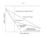
- FIG. 3 is a graph depicting improvements in travel distance that can be expected when a cooling control method for a battery management system in an electric vehicle according to an example embodiment of the present disclosure is used.
- the present disclosure is directed to a method of controlling battery cooling using a battery management system (BMS) that controls the degree of cooling fan operation based on the battery temperature in an electric vehicle equipped with the battery and the cooling fan.
- BMS battery management system
- application of the present disclosure is not limited to electric vehicles but also may be applied to control of cooling of various batteries mounted in vehicles.
- the present invention may be applied to a battery mounted in a hybrid electric vehicle (HEV).
- HEV hybrid electric vehicle
- FIG. 1 is a flowchart illustrating a cooling control method for a battery management system in an electric vehicle according to an example embodiment.
- the degree of cooling fan operation is increased compared to the degree of cooling fan operation applied under normal conditions when an actual battery durability deterioration rate Vt measured using battery durability deterioration information during vehicle operation is higher than a predicted batter durability deterioration rate Vp.
- a normal mode M 1 for controlling the degree of cooling fan operation based on battery temperature in a normal operating environment is set.
- the degree of cooling fan operation is indicated by a stage index.
- normal mode M 1 can be set as shown in Table 1 below.
- a deterioration attenuation mode M 2 in which the degree of cooling operation of is increased above the normal mode M 1 based on battery temperature is set.
- the set deterioration attenuation mode M 2 include a first deterioration attenuation mode M 2 - 1 , in which the degree of cooling fan operation is increased above the normal mode M 1 based on battery temperature, and a second deterioration attenuation mode M 2 - 2 , in which the degree of cooling fan operation is increased above first deterioration attenuation mode M 2 - 1 .
- first deterioration attenuation mode M 2 - 1 and second deterioration attenuation mode M 2 - 2 can be set as shown in Table 1 below.
- a reference value Vc for dividing deterioration attenuation mode M 2 into first deterioration attenuation mode M 2 - 1 and second deterioration attenuation mode M 2 - 2 is set by the operator according to the degree of battery durability deterioration. Any reference value Vc may be set through various variables such as the capacity of the battery.
- the predicted battery durability deterioration rate Vp is set to increase in proportion to the travel distance.
- the predicted battery durability deterioration rate Vp is a theoretical expected value without considering abnormal parameters.
- the cooling control method for the BMS is applied while the vehicle is running.
- the battery durability deterioration rate is monitored in real time using the battery durability deterioration information.
- Battery durability deterioration rate can be monitored using various methods. For example, the capacity (voltage) of the battery can be measured in real time, and the durability deterioration rate can be calculated in accordance with the amount of change in capacity.
- the cooling fan is operated in the first deterioration attenuation mode M 2 - 1 .
- the cooling fan is operated in the second deterioration attenuation mode M 2 - 2 .
- control method checks whether the battery guaranteed distance can be expected to be ensured by controlling the cooling fan according to the cooling control method for the BMS in an electric vehicle.
- FIG. 2 is a graph depicting the change in battery temperature based on a cooling condition of the battery, wherein the comparative example illustrates control of the cooling fan in the normal mode M 1 during vehicle operation, and the embodiment illustrates control of the cooling fan in the deterioration attenuation mode M 2 during vehicle operation.
- the battery temperature distribution using the example embodiment is shifted to a lower temperature range than in the comparative example, and as a result, durability of the battery is improved using the example embodiment by about 10%.
- the result confirms that the rate of battery deterioration can be controlled by adjusting the degree of battery cooling in accordance with the example embodiments described above.
- FIG. 3 is a graph depicting improvements in travel distance that can be expected when a cooling control method for a battery management system in an electric vehicle according to an example embodiment is used.
- the expected value line represents a theoretical case in which any abnormal parameter that may change the capacity of the battery is not considered.
- the comparative example illustrates control of the cooling fan in the normal mode M 1 during vehicle operation
- the example embodiment illustrates control of the cooling fan in the deterioration attenuation mode M 2 during vehicle operation.
- the capacity of the battery is significantly reduced as travel distance increases, compared to the expected value. Therefore, it can be predicted that the battery guaranteed distance cannot be ensured when the cooling fan is controlled in the normal mode M 1 alone.
- the decrease in the battery capacity is greatly attenuated compared to the comparative example. Therefore, it is expected that decrease in the battery capacity will be attenuated and the guaranteed distance of the battery can be ensured when the cooling fan is controlled in the deterioration attenuation mode M 2 .
- the degree of cooling fan operation is adjusted by using the real-time measured battery temperature and an assessment of the rate of deterioration in battery durability. Thereby, the service life of the battery may be improved.
Landscapes
- Engineering & Computer Science (AREA)
- Manufacturing & Machinery (AREA)
- Chemical & Material Sciences (AREA)
- Chemical Kinetics & Catalysis (AREA)
- Electrochemistry (AREA)
- General Chemical & Material Sciences (AREA)
- Power Engineering (AREA)
- Mechanical Engineering (AREA)
- Transportation (AREA)
- Sustainable Energy (AREA)
- Sustainable Development (AREA)
- Life Sciences & Earth Sciences (AREA)
- Automation & Control Theory (AREA)
- Physics & Mathematics (AREA)
- Thermal Sciences (AREA)
- Electric Propulsion And Braking For Vehicles (AREA)
- Secondary Cells (AREA)
Abstract
Description
| TABLE 1 | ||
| First | Second | |
| deterioration | deterioration | |
| Normal mode | attenuation mode | attenuation mode |
| (M1) | (M2-1) | (M2-2) |
| Battery | Cooling | Battery | Cooling | Battery | Cooling |
| temperature | fan | temperature | fan | temperature | fan |
| (° C.) | stage | (° C.) | stage | (° C.) | |
| 30 | 2 | 30 | 5 | 30 | 9 |
| 40 | 5 | 40 | 7 | 40 | 9 |
| 50 | 7 | 50 | 8 | 50 | 9 |
| 60 | 9 | 60 | 9 | 60 | 9 |
Claims (5)
Applications Claiming Priority (2)
| Application Number | Priority Date | Filing Date | Title |
|---|---|---|---|
| KR10-2016-0169992 | 2016-12-13 | ||
| KR1020160169992A KR20180068391A (en) | 2016-12-13 | 2016-12-13 | Cooling control method of battery management system in electric vehicle |
Publications (2)
| Publication Number | Publication Date |
|---|---|
| US20180326862A1 US20180326862A1 (en) | 2018-11-15 |
| US10464437B2 true US10464437B2 (en) | 2019-11-05 |
Family
ID=62768447
Family Applications (1)
| Application Number | Title | Priority Date | Filing Date |
|---|---|---|---|
| US15/838,951 Active US10464437B2 (en) | 2016-12-13 | 2017-12-12 | Cooling control method for battery management system in electric vehicle |
Country Status (3)
| Country | Link |
|---|---|
| US (1) | US10464437B2 (en) |
| KR (1) | KR20180068391A (en) |
| CN (1) | CN108461860B (en) |
Families Citing this family (8)
| Publication number | Priority date | Publication date | Assignee | Title |
|---|---|---|---|---|
| KR102542958B1 (en) * | 2017-12-12 | 2023-06-14 | 현대자동차주식회사 | Controlling method and system for monitoring deterioration of battery of vehicle |
| CN112103593A (en) * | 2019-06-17 | 2020-12-18 | 比亚迪股份有限公司 | Vehicle thermal management method, device, vehicle and storage medium |
| CN110350267A (en) * | 2019-06-26 | 2019-10-18 | 河南美力达汽车有限公司 | A kind of batteries of electric automobile group cooling control system |
| EP3865338A1 (en) | 2020-02-13 | 2021-08-18 | Ningbo Geely Automobile Research & Development Co. Ltd. | A vehicle control system for optimizing energy consumption |
| GB2594979B (en) * | 2020-05-14 | 2024-04-24 | Jaguar Land Rover Ltd | Thermal management of vehicle energy storage means |
| GB2594978B (en) | 2020-05-14 | 2024-04-24 | Jaguar Land Rover Ltd | Thermal management of vehicle energy storage means |
| CN113686916A (en) * | 2020-05-18 | 2021-11-23 | 郑州深澜动力科技有限公司 | Test system and test method for detecting cooling effect of power battery system |
| CN118367263B (en) * | 2024-04-23 | 2024-10-15 | 东莞市智高实业有限公司 | New energy automobile battery heat dissipation system and method |
Citations (2)
| Publication number | Priority date | Publication date | Assignee | Title |
|---|---|---|---|---|
| KR20130017286A (en) | 2011-08-10 | 2013-02-20 | 현대자동차주식회사 | Cooling control method of high voltage battery system in electric vehicle |
| US20130076313A1 (en) * | 2011-09-26 | 2013-03-28 | Kia Motors Corporation | Battery charging control technique for vehicle |
Family Cites Families (6)
| Publication number | Priority date | Publication date | Assignee | Title |
|---|---|---|---|---|
| JP2007048485A (en) * | 2005-08-05 | 2007-02-22 | Nissan Motor Co Ltd | Vehicle battery cooling system |
| JP4975715B2 (en) * | 2008-11-20 | 2012-07-11 | 住友重機械工業株式会社 | Charge / discharge control device |
| KR101558655B1 (en) * | 2013-07-16 | 2015-10-07 | 현대자동차주식회사 | Cooling control method for battery of vehicle |
| US20150291054A1 (en) * | 2014-04-15 | 2015-10-15 | Ford Global Technologies, Llc | Traction Battery Air Thermal Management Control System |
| JP6217618B2 (en) * | 2014-12-24 | 2017-10-25 | トヨタ自動車株式会社 | Control device for hybrid vehicle |
| JP6269559B2 (en) * | 2015-04-10 | 2018-01-31 | トヨタ自動車株式会社 | In-vehicle secondary battery cooling system |
-
2016
- 2016-12-13 KR KR1020160169992A patent/KR20180068391A/en not_active Ceased
-
2017
- 2017-08-18 CN CN201710711404.5A patent/CN108461860B/en active Active
- 2017-12-12 US US15/838,951 patent/US10464437B2/en active Active
Patent Citations (2)
| Publication number | Priority date | Publication date | Assignee | Title |
|---|---|---|---|---|
| KR20130017286A (en) | 2011-08-10 | 2013-02-20 | 현대자동차주식회사 | Cooling control method of high voltage battery system in electric vehicle |
| US20130076313A1 (en) * | 2011-09-26 | 2013-03-28 | Kia Motors Corporation | Battery charging control technique for vehicle |
Also Published As
| Publication number | Publication date |
|---|---|
| US20180326862A1 (en) | 2018-11-15 |
| KR20180068391A (en) | 2018-06-22 |
| CN108461860B (en) | 2023-09-26 |
| CN108461860A (en) | 2018-08-28 |
Similar Documents
| Publication | Publication Date | Title |
|---|---|---|
| US10464437B2 (en) | Cooling control method for battery management system in electric vehicle | |
| US12005810B2 (en) | Cooling strategy for battery systems | |
| KR101998069B1 (en) | Method and apparatus for fast charging and maximum discharging with less-degradation of battery for an electric car | |
| EP1806248B1 (en) | Method for controlling an electric vehicle | |
| US11807213B2 (en) | Method for managing the state of charge of a hybrid vehicle | |
| CN106058360B (en) | The cooling system of vehicle-mounted secondary cell | |
| US10547089B2 (en) | Optimization of cruising voltage for life and fuel economy performance in advanced start-stop systems | |
| US20090218987A1 (en) | Battery management control system | |
| US9632125B2 (en) | Harness anomaly detection systems and methods | |
| US7629770B2 (en) | Device and method for controlling output from a rechargeable battery | |
| US10017069B2 (en) | Method for controlling battery output | |
| JP2019057455A (en) | Secondary battery control device and control method | |
| KR20150066355A (en) | Battery cooling fan control system for environmental friendly vehicle and method thereof | |
| CN103358886A (en) | Cooling fan control device | |
| KR20190046133A (en) | Method for Controlling Cooling of Battery | |
| KR102056476B1 (en) | Small Rechargeable Battery Matrix Control Apparatus and Method For an Electric Vehicle | |
| JP2013158128A (en) | Vehicle | |
| JP2018055906A (en) | Control device for battery temperature control unit | |
| WO2017168875A1 (en) | Switching control device and switching control method | |
| JP4645566B2 (en) | Electric vehicle capacity adjustment device | |
| CN111855231A (en) | Operating method for calibrating thermal performance parameters of power system of new energy automobile | |
| JP7206079B2 (en) | Storage battery cooling control device and electric vehicle | |
| KR20250088068A (en) | Method and apparatus for battery conditioning of eco-friendly vehicle | |
| KR20220122329A (en) | Battery with improved low-temperature startability, Vehicle including the same |
Legal Events
| Date | Code | Title | Description |
|---|---|---|---|
| FEPP | Fee payment procedure |
Free format text: ENTITY STATUS SET TO UNDISCOUNTED (ORIGINAL EVENT CODE: BIG.); ENTITY STATUS OF PATENT OWNER: LARGE ENTITY |
|
| AS | Assignment |
Owner name: HYUNDAI MOTOR COMPANY, KOREA, REPUBLIC OF Free format text: ASSIGNMENT OF ASSIGNORS INTEREST;ASSIGNORS:WOO, JUNG JE;SHIN, WOO JIN;KIM, SUK HYUNG;AND OTHERS;REEL/FRAME:044440/0268 Effective date: 20170615 Owner name: KIA MOTORS CORPORATION, KOREA, REPUBLIC OF Free format text: ASSIGNMENT OF ASSIGNORS INTEREST;ASSIGNORS:WOO, JUNG JE;SHIN, WOO JIN;KIM, SUK HYUNG;AND OTHERS;REEL/FRAME:044440/0268 Effective date: 20170615 |
|
| STPP | Information on status: patent application and granting procedure in general |
Free format text: RESPONSE TO NON-FINAL OFFICE ACTION ENTERED AND FORWARDED TO EXAMINER |
|
| STPP | Information on status: patent application and granting procedure in general |
Free format text: NON FINAL ACTION MAILED |
|
| STPP | Information on status: patent application and granting procedure in general |
Free format text: NOTICE OF ALLOWANCE MAILED -- APPLICATION RECEIVED IN OFFICE OF PUBLICATIONS |
|
| STPP | Information on status: patent application and granting procedure in general |
Free format text: PUBLICATIONS -- ISSUE FEE PAYMENT VERIFIED |
|
| STCF | Information on status: patent grant |
Free format text: PATENTED CASE |
|
| MAFP | Maintenance fee payment |
Free format text: PAYMENT OF MAINTENANCE FEE, 4TH YEAR, LARGE ENTITY (ORIGINAL EVENT CODE: M1551); ENTITY STATUS OF PATENT OWNER: LARGE ENTITY Year of fee payment: 4 |