JP6217618B2 - Control device for hybrid vehicle - Google Patents
Control device for hybrid vehicle Download PDFInfo
- Publication number
- JP6217618B2 JP6217618B2 JP2014260843A JP2014260843A JP6217618B2 JP 6217618 B2 JP6217618 B2 JP 6217618B2 JP 2014260843 A JP2014260843 A JP 2014260843A JP 2014260843 A JP2014260843 A JP 2014260843A JP 6217618 B2 JP6217618 B2 JP 6217618B2
- Authority
- JP
- Japan
- Prior art keywords
- cooling fan
- power storage
- storage device
- vehicle
- power
- Prior art date
- Legal status (The legal status is an assumption and is not a legal conclusion. Google has not performed a legal analysis and makes no representation as to the accuracy of the status listed.)
- Active
Links
Images
Classifications
-
- B—PERFORMING OPERATIONS; TRANSPORTING
- B60—VEHICLES IN GENERAL
- B60L—PROPULSION OF ELECTRICALLY-PROPELLED VEHICLES; SUPPLYING ELECTRIC POWER FOR AUXILIARY EQUIPMENT OF ELECTRICALLY-PROPELLED VEHICLES; ELECTRODYNAMIC BRAKE SYSTEMS FOR VEHICLES IN GENERAL; MAGNETIC SUSPENSION OR LEVITATION FOR VEHICLES; MONITORING OPERATING VARIABLES OF ELECTRICALLY-PROPELLED VEHICLES; ELECTRIC SAFETY DEVICES FOR ELECTRICALLY-PROPELLED VEHICLES
- B60L53/00—Methods of charging batteries, specially adapted for electric vehicles; Charging stations or on-board charging equipment therefor; Exchange of energy storage elements in electric vehicles
- B60L53/50—Charging stations characterised by energy-storage or power-generation means
- B60L53/57—Charging stations without connection to power networks
-
- B—PERFORMING OPERATIONS; TRANSPORTING
- B60—VEHICLES IN GENERAL
- B60L—PROPULSION OF ELECTRICALLY-PROPELLED VEHICLES; SUPPLYING ELECTRIC POWER FOR AUXILIARY EQUIPMENT OF ELECTRICALLY-PROPELLED VEHICLES; ELECTRODYNAMIC BRAKE SYSTEMS FOR VEHICLES IN GENERAL; MAGNETIC SUSPENSION OR LEVITATION FOR VEHICLES; MONITORING OPERATING VARIABLES OF ELECTRICALLY-PROPELLED VEHICLES; ELECTRIC SAFETY DEVICES FOR ELECTRICALLY-PROPELLED VEHICLES
- B60L58/00—Methods or circuit arrangements for monitoring or controlling batteries or fuel cells, specially adapted for electric vehicles
- B60L58/10—Methods or circuit arrangements for monitoring or controlling batteries or fuel cells, specially adapted for electric vehicles for monitoring or controlling batteries
- B60L58/12—Methods or circuit arrangements for monitoring or controlling batteries or fuel cells, specially adapted for electric vehicles for monitoring or controlling batteries responding to state of charge [SoC]
-
- B—PERFORMING OPERATIONS; TRANSPORTING
- B60—VEHICLES IN GENERAL
- B60L—PROPULSION OF ELECTRICALLY-PROPELLED VEHICLES; SUPPLYING ELECTRIC POWER FOR AUXILIARY EQUIPMENT OF ELECTRICALLY-PROPELLED VEHICLES; ELECTRODYNAMIC BRAKE SYSTEMS FOR VEHICLES IN GENERAL; MAGNETIC SUSPENSION OR LEVITATION FOR VEHICLES; MONITORING OPERATING VARIABLES OF ELECTRICALLY-PROPELLED VEHICLES; ELECTRIC SAFETY DEVICES FOR ELECTRICALLY-PROPELLED VEHICLES
- B60L58/00—Methods or circuit arrangements for monitoring or controlling batteries or fuel cells, specially adapted for electric vehicles
- B60L58/10—Methods or circuit arrangements for monitoring or controlling batteries or fuel cells, specially adapted for electric vehicles for monitoring or controlling batteries
- B60L58/24—Methods or circuit arrangements for monitoring or controlling batteries or fuel cells, specially adapted for electric vehicles for monitoring or controlling batteries for controlling the temperature of batteries
- B60L58/26—Methods or circuit arrangements for monitoring or controlling batteries or fuel cells, specially adapted for electric vehicles for monitoring or controlling batteries for controlling the temperature of batteries by cooling
-
- B—PERFORMING OPERATIONS; TRANSPORTING
- B60—VEHICLES IN GENERAL
- B60W—CONJOINT CONTROL OF VEHICLE SUB-UNITS OF DIFFERENT TYPE OR DIFFERENT FUNCTION; CONTROL SYSTEMS SPECIALLY ADAPTED FOR HYBRID VEHICLES; ROAD VEHICLE DRIVE CONTROL SYSTEMS FOR PURPOSES NOT RELATED TO THE CONTROL OF A PARTICULAR SUB-UNIT
- B60W10/00—Conjoint control of vehicle sub-units of different type or different function
- B60W10/04—Conjoint control of vehicle sub-units of different type or different function including control of propulsion units
- B60W10/06—Conjoint control of vehicle sub-units of different type or different function including control of propulsion units including control of combustion engines
-
- B—PERFORMING OPERATIONS; TRANSPORTING
- B60—VEHICLES IN GENERAL
- B60W—CONJOINT CONTROL OF VEHICLE SUB-UNITS OF DIFFERENT TYPE OR DIFFERENT FUNCTION; CONTROL SYSTEMS SPECIALLY ADAPTED FOR HYBRID VEHICLES; ROAD VEHICLE DRIVE CONTROL SYSTEMS FOR PURPOSES NOT RELATED TO THE CONTROL OF A PARTICULAR SUB-UNIT
- B60W10/00—Conjoint control of vehicle sub-units of different type or different function
- B60W10/04—Conjoint control of vehicle sub-units of different type or different function including control of propulsion units
- B60W10/08—Conjoint control of vehicle sub-units of different type or different function including control of propulsion units including control of electric propulsion units, e.g. motors or generators
-
- B—PERFORMING OPERATIONS; TRANSPORTING
- B60—VEHICLES IN GENERAL
- B60W—CONJOINT CONTROL OF VEHICLE SUB-UNITS OF DIFFERENT TYPE OR DIFFERENT FUNCTION; CONTROL SYSTEMS SPECIALLY ADAPTED FOR HYBRID VEHICLES; ROAD VEHICLE DRIVE CONTROL SYSTEMS FOR PURPOSES NOT RELATED TO THE CONTROL OF A PARTICULAR SUB-UNIT
- B60W10/00—Conjoint control of vehicle sub-units of different type or different function
- B60W10/30—Conjoint control of vehicle sub-units of different type or different function including control of auxiliary equipment, e.g. air-conditioning compressors or oil pumps
-
- B—PERFORMING OPERATIONS; TRANSPORTING
- B60—VEHICLES IN GENERAL
- B60W—CONJOINT CONTROL OF VEHICLE SUB-UNITS OF DIFFERENT TYPE OR DIFFERENT FUNCTION; CONTROL SYSTEMS SPECIALLY ADAPTED FOR HYBRID VEHICLES; ROAD VEHICLE DRIVE CONTROL SYSTEMS FOR PURPOSES NOT RELATED TO THE CONTROL OF A PARTICULAR SUB-UNIT
- B60W20/00—Control systems specially adapted for hybrid vehicles
- B60W20/10—Controlling the power contribution of each of the prime movers to meet required power demand
- B60W20/13—Controlling the power contribution of each of the prime movers to meet required power demand in order to stay within battery power input or output limits; in order to prevent overcharging or battery depletion
-
- H—ELECTRICITY
- H01—ELECTRIC ELEMENTS
- H01M—PROCESSES OR MEANS, e.g. BATTERIES, FOR THE DIRECT CONVERSION OF CHEMICAL ENERGY INTO ELECTRICAL ENERGY
- H01M10/00—Secondary cells; Manufacture thereof
- H01M10/60—Heating or cooling; Temperature control
- H01M10/61—Types of temperature control
- H01M10/613—Cooling or keeping cold
-
- H—ELECTRICITY
- H01—ELECTRIC ELEMENTS
- H01M—PROCESSES OR MEANS, e.g. BATTERIES, FOR THE DIRECT CONVERSION OF CHEMICAL ENERGY INTO ELECTRICAL ENERGY
- H01M10/00—Secondary cells; Manufacture thereof
- H01M10/60—Heating or cooling; Temperature control
- H01M10/62—Heating or cooling; Temperature control specially adapted for specific applications
- H01M10/625—Vehicles
-
- H—ELECTRICITY
- H01—ELECTRIC ELEMENTS
- H01M—PROCESSES OR MEANS, e.g. BATTERIES, FOR THE DIRECT CONVERSION OF CHEMICAL ENERGY INTO ELECTRICAL ENERGY
- H01M10/00—Secondary cells; Manufacture thereof
- H01M10/60—Heating or cooling; Temperature control
- H01M10/63—Control systems
- H01M10/633—Control systems characterised by algorithms, flow charts, software details or the like
-
- H—ELECTRICITY
- H01—ELECTRIC ELEMENTS
- H01M—PROCESSES OR MEANS, e.g. BATTERIES, FOR THE DIRECT CONVERSION OF CHEMICAL ENERGY INTO ELECTRICAL ENERGY
- H01M10/00—Secondary cells; Manufacture thereof
- H01M10/60—Heating or cooling; Temperature control
- H01M10/65—Means for temperature control structurally associated with the cells
- H01M10/656—Means for temperature control structurally associated with the cells characterised by the type of heat-exchange fluid
- H01M10/6561—Gases
- H01M10/6563—Gases with forced flow, e.g. by blowers
-
- B—PERFORMING OPERATIONS; TRANSPORTING
- B60—VEHICLES IN GENERAL
- B60W—CONJOINT CONTROL OF VEHICLE SUB-UNITS OF DIFFERENT TYPE OR DIFFERENT FUNCTION; CONTROL SYSTEMS SPECIALLY ADAPTED FOR HYBRID VEHICLES; ROAD VEHICLE DRIVE CONTROL SYSTEMS FOR PURPOSES NOT RELATED TO THE CONTROL OF A PARTICULAR SUB-UNIT
- B60W2510/00—Input parameters relating to a particular sub-units
- B60W2510/24—Energy storage means
- B60W2510/242—Energy storage means for electrical energy
- B60W2510/244—Charge state
-
- B—PERFORMING OPERATIONS; TRANSPORTING
- B60—VEHICLES IN GENERAL
- B60W—CONJOINT CONTROL OF VEHICLE SUB-UNITS OF DIFFERENT TYPE OR DIFFERENT FUNCTION; CONTROL SYSTEMS SPECIALLY ADAPTED FOR HYBRID VEHICLES; ROAD VEHICLE DRIVE CONTROL SYSTEMS FOR PURPOSES NOT RELATED TO THE CONTROL OF A PARTICULAR SUB-UNIT
- B60W2510/00—Input parameters relating to a particular sub-units
- B60W2510/24—Energy storage means
- B60W2510/242—Energy storage means for electrical energy
- B60W2510/246—Temperature
-
- B—PERFORMING OPERATIONS; TRANSPORTING
- B60—VEHICLES IN GENERAL
- B60W—CONJOINT CONTROL OF VEHICLE SUB-UNITS OF DIFFERENT TYPE OR DIFFERENT FUNCTION; CONTROL SYSTEMS SPECIALLY ADAPTED FOR HYBRID VEHICLES; ROAD VEHICLE DRIVE CONTROL SYSTEMS FOR PURPOSES NOT RELATED TO THE CONTROL OF A PARTICULAR SUB-UNIT
- B60W2710/00—Output or target parameters relating to a particular sub-units
- B60W2710/24—Energy storage means
- B60W2710/242—Energy storage means for electrical energy
- B60W2710/246—Temperature
-
- H—ELECTRICITY
- H01—ELECTRIC ELEMENTS
- H01M—PROCESSES OR MEANS, e.g. BATTERIES, FOR THE DIRECT CONVERSION OF CHEMICAL ENERGY INTO ELECTRICAL ENERGY
- H01M2220/00—Batteries for particular applications
- H01M2220/20—Batteries in motive systems, e.g. vehicle, ship, plane
-
- Y—GENERAL TAGGING OF NEW TECHNOLOGICAL DEVELOPMENTS; GENERAL TAGGING OF CROSS-SECTIONAL TECHNOLOGIES SPANNING OVER SEVERAL SECTIONS OF THE IPC; TECHNICAL SUBJECTS COVERED BY FORMER USPC CROSS-REFERENCE ART COLLECTIONS [XRACs] AND DIGESTS
- Y02—TECHNOLOGIES OR APPLICATIONS FOR MITIGATION OR ADAPTATION AGAINST CLIMATE CHANGE
- Y02E—REDUCTION OF GREENHOUSE GAS [GHG] EMISSIONS, RELATED TO ENERGY GENERATION, TRANSMISSION OR DISTRIBUTION
- Y02E60/00—Enabling technologies; Technologies with a potential or indirect contribution to GHG emissions mitigation
- Y02E60/10—Energy storage using batteries
-
- Y—GENERAL TAGGING OF NEW TECHNOLOGICAL DEVELOPMENTS; GENERAL TAGGING OF CROSS-SECTIONAL TECHNOLOGIES SPANNING OVER SEVERAL SECTIONS OF THE IPC; TECHNICAL SUBJECTS COVERED BY FORMER USPC CROSS-REFERENCE ART COLLECTIONS [XRACs] AND DIGESTS
- Y02—TECHNOLOGIES OR APPLICATIONS FOR MITIGATION OR ADAPTATION AGAINST CLIMATE CHANGE
- Y02T—CLIMATE CHANGE MITIGATION TECHNOLOGIES RELATED TO TRANSPORTATION
- Y02T10/00—Road transport of goods or passengers
- Y02T10/60—Other road transportation technologies with climate change mitigation effect
- Y02T10/62—Hybrid vehicles
-
- Y—GENERAL TAGGING OF NEW TECHNOLOGICAL DEVELOPMENTS; GENERAL TAGGING OF CROSS-SECTIONAL TECHNOLOGIES SPANNING OVER SEVERAL SECTIONS OF THE IPC; TECHNICAL SUBJECTS COVERED BY FORMER USPC CROSS-REFERENCE ART COLLECTIONS [XRACs] AND DIGESTS
- Y02—TECHNOLOGIES OR APPLICATIONS FOR MITIGATION OR ADAPTATION AGAINST CLIMATE CHANGE
- Y02T—CLIMATE CHANGE MITIGATION TECHNOLOGIES RELATED TO TRANSPORTATION
- Y02T10/00—Road transport of goods or passengers
- Y02T10/60—Other road transportation technologies with climate change mitigation effect
- Y02T10/70—Energy storage systems for electromobility, e.g. batteries
-
- Y—GENERAL TAGGING OF NEW TECHNOLOGICAL DEVELOPMENTS; GENERAL TAGGING OF CROSS-SECTIONAL TECHNOLOGIES SPANNING OVER SEVERAL SECTIONS OF THE IPC; TECHNICAL SUBJECTS COVERED BY FORMER USPC CROSS-REFERENCE ART COLLECTIONS [XRACs] AND DIGESTS
- Y02—TECHNOLOGIES OR APPLICATIONS FOR MITIGATION OR ADAPTATION AGAINST CLIMATE CHANGE
- Y02T—CLIMATE CHANGE MITIGATION TECHNOLOGIES RELATED TO TRANSPORTATION
- Y02T10/00—Road transport of goods or passengers
- Y02T10/60—Other road transportation technologies with climate change mitigation effect
- Y02T10/7072—Electromobility specific charging systems or methods for batteries, ultracapacitors, supercapacitors or double-layer capacitors
-
- Y—GENERAL TAGGING OF NEW TECHNOLOGICAL DEVELOPMENTS; GENERAL TAGGING OF CROSS-SECTIONAL TECHNOLOGIES SPANNING OVER SEVERAL SECTIONS OF THE IPC; TECHNICAL SUBJECTS COVERED BY FORMER USPC CROSS-REFERENCE ART COLLECTIONS [XRACs] AND DIGESTS
- Y02—TECHNOLOGIES OR APPLICATIONS FOR MITIGATION OR ADAPTATION AGAINST CLIMATE CHANGE
- Y02T—CLIMATE CHANGE MITIGATION TECHNOLOGIES RELATED TO TRANSPORTATION
- Y02T90/00—Enabling technologies or technologies with a potential or indirect contribution to GHG emissions mitigation
- Y02T90/10—Technologies relating to charging of electric vehicles
- Y02T90/12—Electric charging stations
-
- Y—GENERAL TAGGING OF NEW TECHNOLOGICAL DEVELOPMENTS; GENERAL TAGGING OF CROSS-SECTIONAL TECHNOLOGIES SPANNING OVER SEVERAL SECTIONS OF THE IPC; TECHNICAL SUBJECTS COVERED BY FORMER USPC CROSS-REFERENCE ART COLLECTIONS [XRACs] AND DIGESTS
- Y02—TECHNOLOGIES OR APPLICATIONS FOR MITIGATION OR ADAPTATION AGAINST CLIMATE CHANGE
- Y02T—CLIMATE CHANGE MITIGATION TECHNOLOGIES RELATED TO TRANSPORTATION
- Y02T90/00—Enabling technologies or technologies with a potential or indirect contribution to GHG emissions mitigation
- Y02T90/10—Technologies relating to charging of electric vehicles
- Y02T90/14—Plug-in electric vehicles
-
- Y—GENERAL TAGGING OF NEW TECHNOLOGICAL DEVELOPMENTS; GENERAL TAGGING OF CROSS-SECTIONAL TECHNOLOGIES SPANNING OVER SEVERAL SECTIONS OF THE IPC; TECHNICAL SUBJECTS COVERED BY FORMER USPC CROSS-REFERENCE ART COLLECTIONS [XRACs] AND DIGESTS
- Y10—TECHNICAL SUBJECTS COVERED BY FORMER USPC
- Y10S—TECHNICAL SUBJECTS COVERED BY FORMER USPC CROSS-REFERENCE ART COLLECTIONS [XRACs] AND DIGESTS
- Y10S903/00—Hybrid electric vehicles, HEVS
- Y10S903/902—Prime movers comprising electrical and internal combustion motors
- Y10S903/903—Prime movers comprising electrical and internal combustion motors having energy storing means, e.g. battery, capacitor
Landscapes
- Engineering & Computer Science (AREA)
- Chemical & Material Sciences (AREA)
- Transportation (AREA)
- Mechanical Engineering (AREA)
- Combustion & Propulsion (AREA)
- Power Engineering (AREA)
- Chemical Kinetics & Catalysis (AREA)
- Manufacturing & Machinery (AREA)
- Electrochemistry (AREA)
- General Chemical & Material Sciences (AREA)
- Automation & Control Theory (AREA)
- Life Sciences & Earth Sciences (AREA)
- Sustainable Development (AREA)
- Sustainable Energy (AREA)
- Electric Propulsion And Braking For Vehicles (AREA)
- Hybrid Electric Vehicles (AREA)
- Secondary Cells (AREA)
Description
本発明は、車両駆動用の内燃機関および回転電機を有するハイブリッド車両の制御に関し、特に回転電機との間で電力の授受を行う蓄電装置の冷却の制御に関する。 The present invention relates to control of a hybrid vehicle having an internal combustion engine for driving a vehicle and a rotating electrical machine, and more particularly to control of cooling of a power storage device that transfers power to and from the rotating electrical machine.
車両駆動用の原動機として内燃機関および回転電機を備えた車両、いわゆるハイブリッド車両が知られている。本明細書において、「回転電機」は、電動機、発電機、さらに電動機と発電機のどちらにも機能する電気機器の総称として用いる。ハイブリッド車両は、回転電機との間で電力の授受を行う蓄電装置を有する。下記特許文献1には、車両の利用者(例えば運転者)の要求に応じて蓄電装置の蓄電量が増量されるハイブリッド車両が示されている。
As a prime mover for driving a vehicle, a vehicle including an internal combustion engine and a rotating electric machine, a so-called hybrid vehicle is known. In this specification, “rotary electric machine” is used as a general term for an electric motor, a generator, and electric devices that function as both the electric motor and the generator. The hybrid vehicle has a power storage device that exchanges electric power with a rotating electrical machine.
蓄電量の増量が要求され、蓄電装置への充電が行われる場合、その後には回転電機のみにより車両を駆動する走行が行われる可能性が高い。回転電機のみの走行においては、回転電機の出力が大きくなり、蓄電装置は回転電機に多くの電力を供給するため発熱し、その温度が上昇する場合がある。 When an increase in the amount of power storage is required and charging of the power storage device is performed, there is a high possibility that the vehicle is driven only by the rotating electrical machine thereafter. In traveling with only the rotating electrical machine, the output of the rotating electrical machine increases, and the power storage device generates heat to supply a large amount of electric power to the rotating electrical machine, and its temperature may rise.
本発明は、車両の使用者の要求に基づき蓄電装置への充電が行われた後の走行において、または予測された回転電機のみによる走行において、蓄電装置の温度上昇を抑制することを目的とする。 An object of the present invention is to suppress an increase in temperature of a power storage device during traveling after charging of the power storage device based on a request of a user of the vehicle, or during traveling using only a predicted rotating electrical machine. .
本発明に係るハイブリッド車両の制御装置は、車両駆動用の内燃機関および回転電機と、回転電機との間で電力の授受を行う蓄電装置と、蓄電装置を冷却するための冷却ファンとを有するハイブリッド車両を制御する。制御装置は、蓄電装置の充放電電力と使用者の意思に基づく充電要求の有無とに基づいて冷却ファンの動作を決定する冷却ファン制御部を有する。冷却ファン制御部は、使用者の意思による充電要求がある場合は、同じ充放電電力であってかつ使用者の意思による充電要求がない場合に比べて蓄電装置がより冷却されるよう冷却ファンの動作を制御する。使用者の意思に基づく充電要求があった後の回転電機の高出力運転に備え、冷却ファンは蓄電装置がより冷却されるよう動作し、蓄電装置の温度上昇を抑制する。 A control apparatus for a hybrid vehicle according to the present invention includes a hybrid having an internal combustion engine and a rotating electrical machine for driving a vehicle, a power storage device that transfers power to and from the rotating electrical machine, and a cooling fan for cooling the power storage device. Control the vehicle. The control device includes a cooling fan control unit that determines the operation of the cooling fan based on the charge / discharge power of the power storage device and the presence / absence of a charge request based on the intention of the user. When there is a charging request at the user's intention, the cooling fan control unit is configured to allow the cooling fan to be cooled more than when the charging / discharging power is the same and there is no charging request at the user's intention. Control the behavior. In preparation for a high-output operation of the rotating electrical machine after a charging request based on the user's intention, the cooling fan operates so that the power storage device is further cooled, and suppresses a temperature rise of the power storage device.
また、他の態様の制御装置は、蓄電装置の蓄電量の増量動作を指令する蓄電量増量スイッチと、蓄電装置の充放電電力と蓄電量増量スイッチのオンオフ状態とに基づいて冷却ファンの動作を決定する冷却ファン制御部と、を有する。冷却ファン制御部は、蓄電量増量スイッチがオン状態の場合は、同じ充放電電力であってかつ蓄電量増量スイッチがオフ状態の場合に比べて蓄電装置がより冷却されるよう冷却ファンの動作を制御する。蓄電量増量スイッチがオン状態にされた後の回転電機の高出力運転に備え、冷却ファンは蓄電装置がより冷却されるよう動作し、蓄電装置の温度上昇を抑制する。 In another aspect, the control device controls the operation of the cooling fan based on the storage amount increase switch for instructing the increase operation of the storage amount of the storage device, the charge / discharge power of the storage device and the on / off state of the storage amount increase switch. And a cooling fan control unit to be determined. The cooling fan control unit operates the cooling fan so that the power storage device is cooled more when the power storage amount increase switch is in the on state than when the power storage amount increase switch is in the off state with the same charge / discharge power. Control. In preparation for the high output operation of the rotating electrical machine after the storage amount increase switch is turned on, the cooling fan operates so that the power storage device is further cooled, and suppresses the temperature rise of the power storage device.
さらにまた、他の態様の制御装置は、回転電機のみによる走行が今後行われるかを予測する回転電機走行予測部と、蓄電装置の充放電電力と回転電機のみによる走行の予測とに基づいて冷却ファンの動作を決定する冷却ファン制御部と、を有する。冷却ファン制御部は、回転電機のみによる走行が予測される場合は、同じ充放電電力であってかつ回転電機のみによる走行が予測されない場合に比べて蓄電装置がより冷却されるよう冷却ファンの動作を制御する。回転電機のみによる走行が予測される場合、そのときの回転電機の高出力運転に備え、冷却ファンは蓄電装置がより冷却されるよう動作し、蓄電装置の温度上昇を抑制する。 Still further, the control device according to another aspect of the present invention is based on a rotating electrical machine traveling prediction unit that predicts whether traveling using only the rotating electrical machine will be performed in the future, and charging / discharging power of the power storage device and traveling prediction using only the rotating electrical machine. A cooling fan control unit that determines the operation of the fan. The cooling fan control unit operates the cooling fan so that the power storage device is cooled more when compared with the case where traveling by only the rotating electrical machine is predicted and when the same charge / discharge power is used and traveling by only the rotating electrical machine is not predicted. To control. When traveling by only the rotating electrical machine is predicted, the cooling fan operates so that the power storage device is further cooled in preparation for high-power operation of the rotating electrical machine at that time, and suppresses the temperature increase of the power storage device.
前記の蓄電装置がより冷却されるようにする冷却ファンの動作の制御は、冷却ファンが動作する下限の温度を低くする制御とすることができる。蓄電装置の温度が低い状態から冷却ファンによる冷却が行われるので、蓄電装置の温度上昇が抑制される。 The control of the operation of the cooling fan that causes the power storage device to be further cooled can be a control that lowers the lower limit temperature at which the cooling fan operates. Since cooling by the cooling fan is performed from a state where the temperature of the power storage device is low, an increase in the temperature of the power storage device is suppressed.
また、前記の蓄電装置がより冷却されるようにする冷却ファンの動作の制御は、冷却ファンの風量を増加する制御とすることができる。蓄電装置への風量が増加するので、蓄電装置の温度上昇が抑制される。 Further, the control of the operation of the cooling fan that causes the power storage device to be further cooled can be a control that increases the air volume of the cooling fan. Since the airflow to the power storage device increases, the temperature rise of the power storage device is suppressed.
ハイブリッド車両の制御装置は、さらに車両の速度を取得する車速取得部を有するものとでき、冷却ファン制御部は、前記の蓄電装置がより冷却されるよう冷却ファンの動作を制御しているときは、車速が高いときは、低いときに比べて冷却ファンの風量を増加させるものとできる。 The hybrid vehicle control device may further include a vehicle speed acquisition unit that acquires the vehicle speed, and the cooling fan control unit controls the operation of the cooling fan so that the power storage device is further cooled. When the vehicle speed is high, the air volume of the cooling fan can be increased compared to when the vehicle speed is low.
ハイブリッド車両の制御装置は、さらに内燃機関の出力を取得する出力取得部を有するものとでき、冷却ファン制御部は、前記の蓄電装置がより冷却されるよう冷却ファンの動作を制御しているときは、内燃機関の出力が大きいときは、小さいときに比べて冷却ファンの風量を増加させるものとできる。 The hybrid vehicle control device may further include an output acquisition unit that acquires the output of the internal combustion engine, and the cooling fan control unit controls the operation of the cooling fan so that the power storage device is further cooled. When the output of the internal combustion engine is large, the air volume of the cooling fan can be increased compared to when the output is small.
ハイブリッド車両は、回転電機のみにより車両を駆動するEVモードと、状況に応じて回転電機と内燃機関を使い分けて、または併用して車両を駆動するHVモードとを切り替えて走行可能であり、冷却ファン制御部は、HVモードで走行しており、かつ前記の蓄電装置がより冷却されるよう冷却ファンの動作を制御しているときは、内燃機関の出力が大きいときは、小さいときに比べて冷却ファンの風量を増加させるものとできる。 The hybrid vehicle can travel by switching between an EV mode in which the vehicle is driven only by the rotating electric machine, and an HV mode in which the rotating electric machine and the internal combustion engine are selectively used according to the situation, or the vehicle is driven in combination. When the control unit is running in the HV mode and controlling the operation of the cooling fan so that the power storage device is further cooled, the control unit cools when the output of the internal combustion engine is large compared to when it is small. The fan's air volume can be increased.
使用者からの蓄電装置への充電要求、蓄電量増量スイッチのオン状態、および回転電機のみによる走行の予測など、今後回転電機が高出力で運転される可能性があるとき、その高出力運転時の前に蓄電装置の温度上昇を抑制しておくことにより、高出力運転時において蓄電装置の温度が高くなることが抑制される。 When there is a possibility that the rotating electrical machine will be operated at a high output in the future, such as when the user requests charging of the power storage device, the storage amount increase switch is turned on, and the prediction of traveling only by the rotating electrical machine, during the high output operation By suppressing the temperature rise of the power storage device before the operation, it is possible to suppress the temperature of the power storage device from increasing during the high output operation.
以下、本発明の実施形態を図面に従って説明する。図1は、本発明に係る車両10の概略構成を示す図である。車両10は、商用電源等の外部電源による充電が可能な、いわゆるプラグインハイブリッド車両である。車両10を駆動する動力装置12は、車両駆動用の原動機として内燃機関14と2機の回転電機16,18を有する。動力装置12は、さらに、3機の原動機14,16,18相互とこれらの原動機と駆動輪20の間で動力のやりとりを行う動力分割装置22を含む。動力分割装置22は、遊星歯車機構を有し、遊星歯車機構のサン要素に一方の回転電機16が、プラネタリ要素に内燃機関14が、リング要素に他方の回転電機18が接続されている。サン要素に接続された回転電機16を第1回転電機16、リング要素に接続された回転電機18を第2回転電機18と記す。リング要素は、動力分割装置22に含まれる減速機構を介して駆動輪20に接続されている。第1および第2回転電機16,18には、電力変換装置24を介して蓄電装置26から電力が供給され、また第1および第2回転電機16,18の発電した電力が蓄電装置26に充電される。電力変換装置24は、蓄電装置26から供給される直流電力を交流電力に変換し、逆に第1および第2回転電機16,18で発電された交流電力を直流電力に変換するインバータを含む。蓄電装置26は、例えば二次電池である。
Hereinafter, embodiments of the present invention will be described with reference to the drawings. FIG. 1 is a diagram showing a schematic configuration of a
動力分割装置22は、内燃機関14の出力を、第1回転電機16を駆動する出力と、駆動輪20に送られ車両を駆動する出力とに分割することができ、このとき第1回転電機16は発電機として機能し、発電された電力は蓄電装置26に充電される。動力分割装置22は、内燃機関14の出力と第2回転電機18の出力を同時に駆動輪20に送ることができる。また、駆動輪20を介して車両の慣性力により第2回転電機18を駆動して第2回転電機18を発電機として機能させることができる。発電された電力は蓄電装置26に充電される。これは、車両の運動エネルギを、電気エネルギに変換することにより減ずる、いわゆる回生制動である。
The
動力装置12の構成は、上述の構成に限られない。例えば、内燃機関が発電機を駆動し、発電された電力によって駆動される電動機によって車両を駆動する構成としてもよい。この場合、内燃機関および発電機は、車両の駆動を直接は行わないが、車両を駆動している電動機に電力を供給しており、間接的に車両の駆動に寄与している。このような原動機(内燃機関および発電機)についても、ここでは車両駆動用の原動機に含める。また、動力装置12は、1機の内燃機関と1機の回転電機から構成されてもよい。
The configuration of the
回転電機のみにより走行するモードを、以下「EVモード」と記す。回転電機と内燃機関の両方を用いて走行するモードを「HVモード」と記す。HVモードにおいては、車速や蓄電装置の蓄電量などの車両の走行状況、および運転者の要求に基づき回転電機と内燃機関を使い分けて、また両者を併用して車両が駆動される。HVモードにおいても、例えば低速走行時には回転電機のみにより車両を駆動するが、状況に応じて内燃機関が始動される状態であり、ここではこの場合の回転電機による走行はEVモードに含まない。 Hereinafter, the mode in which the vehicle is driven only by the rotating electric machine is referred to as “EV mode”. A mode of traveling using both the rotating electrical machine and the internal combustion engine is referred to as an “HV mode”. In the HV mode, the rotating electric machine and the internal combustion engine are selectively used on the basis of the traveling state of the vehicle such as the vehicle speed and the amount of electricity stored in the power storage device, and the driver's request, and the vehicle is driven using both in combination. Even in the HV mode, for example, the vehicle is driven only by the rotating electrical machine during low-speed traveling, but the internal combustion engine is started according to the situation. Here, traveling by the rotating electrical machine in this case is not included in the EV mode.
車両10は、蓄電装置26に外部電源28から充電することができる。車両10に備えられた充電インレット30に、外部電源28に接続された充電コネクタ32を接続して、充電装置34を介して充電を行う。また、蓄電装置26の冷却を行うための冷却ファン36が設けられている。
The
車両10は、車両の使用者(例えば運転者)の要求および車両の状況に基づき内燃機関14、第1および第2回転電機16,18の動作を制御する制御部38を有する。運転者の要求は、アクセルペダル、ブレーキペダル、シフトレバーなどの操作に基づき把握することができる。車両の状況は、例えば車両の速度(車速)、蓄電装置26の蓄電量やその温度などが挙げられる。車速は、駆動輪20またはこれと所定の速度関係を持って回転する要素の回転速度を検出する車速センサ40により検出できる。制御部38は、車速センサ40からの信号に基づき車両の速度を取得する車速取得部として機能する。蓄電装置26の蓄電量は、蓄電装置26の端子電圧や蓄電装置26に出入りする電力に基づき算出することができる。この算出は、制御部38により実行されてよい。蓄電装置26の温度は、蓄電装置26に備えられた温度センサ42により検出でき、制御部38が取得することができる。また、制御部38は、蓄電装置26の状態、例えばそのときの蓄電装置26の充放電電力や温度に基づき冷却ファン36の動作の制御を行う。このとき、制御部38は冷却ファン動作制御部として機能する。例えば、制御部38は、あらかじめ定められた蓄電装置26の充放電電力と冷却ファン36の風量との関係に基づき、そのときの充放電電力に応じた風量となるよう冷却ファン36を制御する。また、制御部38は、蓄電装置26の温度と冷却ファン36の風量との関係をあらかじめ定めておき、そのときの温度に応じた風量となるよう冷却ファン36を制御する。
The
運転者の要求は、上述のアクセルペダル等に加え、EVモードとHVモードを切り替えるモード切替スイッチ44、および蓄電装置26の蓄電量を増量し、満充電状態またはこれに近い蓄電量に回復させる回復スイッチ46を含んでよい。この車両10では、運転者がモード切替スイッチ44を操作すると、EVモードからHVモードに、またはHVモードからEVモードにモードが切り替わる。また、運転者が回復スイッチ46を操作すると、蓄電装置26の蓄電量を増量し、満充電、またはそれに近い蓄電量になるように各原動機14,16,18が制御される。つまり、回復スイッチ46が操作されてオン状態になると、蓄電装置26に充電が行われるよう各原動機14,16,18の動作が制御される。回復スイッチ46のオン状態に基づく各原動機14,16,18および他の機器の動作を以降「回復動作」と記す。回復スイッチ46がオン状態のとき、常に充電が行われる必要はなく、制御部38は、車両の状況に応じてより充電が行われるように、または充電機会が増えるように各原動機14,16,18の動作が制御される。例えば、アクセルペダルが戻された状態では充電を行わず、ブレーキペダルが踏まれた段階で、回復スイッチ46がオフ状態のときより大きな回生制動力が生じるようにして充電量を増やすようにしてよい。回復スイッチ46は、オン状態にされることによって各原動機14,16,18が蓄電装置26の蓄電量を増加するよう指令を行う蓄電量増量スイッチである。また、回復スイッチ46がオン状態のときには、運転者が蓄電装置26の充電を要求していると判断できる。
In response to the driver's request, in addition to the accelerator pedal, etc., the
制御部38は、把握した運転者の要求と車両の状況に基づき、各原動機14,16,18、蓄電装置26等の制御を行う。車両10は、外部充電により蓄電装置26の蓄電量が十分となっているときは、外部充電で充電された電力を使用して走行する。このときは、原則的に回転電機のみにより車両を駆動する。また、外部充電で充電された電力を消費した後、つまり蓄電量が所定値以下となった後は、必要な駆動力を回転電機および内燃機関から得て、一方蓄電装置の蓄電量が所定の範囲になるように制御が行われる。この車両10においては、運行開始時に、外部充電により蓄電装置26が満充電またはそれに近い状態となっている場合、まず第2回転電機18のみによる走行を行う。高速度(例えば100km/h)以上の場合や、運転者が急加速を要求した場合など、高出力が必要な状況が判断されると内燃機関14が始動される。また、車載の空気調和装置からの要求、蓄電装置26や内燃機関14の温度(低温の場合)などの条件からも内燃機関14が始動される場合がある。蓄電量が所定値、例えば60%まで低下すると、内燃機関14と第2回転電機18の一方、または両方で車両を駆動する。どの原動機14,18を用いるかは、運転者の要求および車両の状況に対応してあらかじめ定められており、例えば、低速走行時には内燃機関14を使用せず、第2回転電機18で車両を駆動し、所定の速度以上となると内燃機関14を始動して両方で車両を駆動する。また、蓄電量が所定値、例えば40%に低下すると内燃機関14の出力の一部で第1回転電機16を駆動して発電し、蓄電装置26に充電する。
The
モード切替スイッチ44を運転者が操作することで、運転者の要求するモードに切り替えることができる。HVモードで運行中にモード切替スイッチ44を操作することで、EVモード、つまり第2回転電機18のみにより車両を駆動するようにできる。EVモードでは内燃機関14が運転されないため、騒音を低減することができる。再度、モード切替スイッチ44を操作することでHVモードに復帰することができる。また、EVモードで運行中にモード切替スイッチ44を操作することで、HVモードへ移行することができる。HVモードで走行することにより、蓄電装置26の蓄電量を温存することができる。再度、モード切替スイッチ44を操作することでEVモードに復帰することができる。
When the driver operates the
回復スイッチ46は、蓄電装置26への充電を要求するスイッチであり、オン状態のときには充電が促進され、蓄電装置26の蓄電量が増加される。回復スイッチ46がオン状態に操作されると、蓄電量が増量されるように各原動機14,16,18の動作が制御される。具体的には、第1回転電機16による発電、回生制動における制動力の増加などにより充電を行い、蓄電量の増量を行う。制御部38は、回復スイッチ46がオン状態にされると、充電の要求があったと判断し、各原動機14,16,18に対して蓄電量を増量する動作を行うように指令を行う。外部から充電された電力を消費した後の運行において、回復スイッチ46が操作されると、蓄電量の上限値が通常の上限値より高くされ、変更された上限値まで充電が行われる。上限値が高くされたことにより、その上限値を目標として各原動機14,16,18の制御が行われ、蓄電量が増量されるように制御される。例えば、回復スイッチ46がオフ状態のときに蓄電量が40〜60%の範囲で管理されている場合、回復スイッチ46がオン状態となると、通常の蓄電量の上限値(60%)が満充電またはそれに近い値(例えば90%)に変更される。
The
外部から充電された電力を使って運行しているときに、回復スイッチ46が操作されると、蓄電装置26の蓄電量が減少しないような制御が実行される。例えば、内燃機関14の駆動力によって車両を駆動するようにする。内燃機関14を始動するために、制御部38はHVモードへの切り替えを行う。また、長い下り坂を走行しているときには、内燃機関14を始動せず、つまりHVモードへの切り替えをせず、回生制動時の第2回転電機18による発電量を増やし、蓄電量の回復が図られる。
When the
運転者が回復スイッチ46をオン状態に操作したときには、このあとEVモードにより走行することを考えている可能性が高い。つまり、回復スイッチ46がオン状態とされたときには、今後EVモードによって走行することが予測される。EVモードによる走行の場合、蓄電装置26から第2回転電機18に供給される電力が大きくなり、蓄電装置26の温度が上昇することが見込まれる。温度が上昇すると蓄電装置26の劣化が早まるので、劣化を抑制するために温度上昇を抑えることが望まれる。そこで、蓄電量の回復動作中から蓄電装置26を冷却するようにして、EVモードによる走行が開始される時点における蓄電装置26の温度を下げておくようにする。これにより、EVモードによる走行中の蓄電装置26の温度を、事前に冷却していない場合に比べて低くすることができる。例えば、EVモードによる走行中の蓄電装置26に対する冷却能力が十分でない場合、事前に冷却することにより、不足している冷却能力の一部を補うことができる。
When the driver operates the
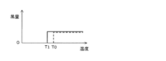
蓄電装置26の冷却は冷却ファン36によって行う。回復スイッチ46がオン状態に操作され回復動作となると、図2に示すように、冷却ファン36の動作下限温度が通常の温度T0より低い温度T1に変更される。例えば、通常であれば蓄電装置26の温度が34℃以下で冷却ファン36が停止する設定を、30℃以下で停止するよう設定を変更する。これにより、冷却ファン36が動作する機会が増え、蓄電装置26がより冷却されるようになる。冷却ファン36の動作機会を増やすことにより、冷却ファン36の風量を変えなくても(つまり、瞬時の冷却能力を増強しなくても)、比較的長い時間における冷却能力が増強されることになる。よって、回復スイッチ46がオン状態のときに、オフ状態のときよりも冷却ファンの動作下限温度を低い温度に変更する制御は、蓄電装置26をより冷却する冷却増強制御である。この冷却増強制御により、蓄電装置26の温度上昇が抑制される。また、冷却ファン36が動作を開始する温度を停止する温度より高くして(例えば2℃高くする)、頻繁なオンオフ動作の繰り返しを防止するようにしてもよい。冷却ファン36が動作しているとき(オンのとき)の風量は、固定値であってよい。また、風量は、そのときの蓄電装置26の充放電電力に応じて変化する値としてもよい。さらにまた、風量は、蓄電装置26の温度に応じて変化する値としてもよい。
The
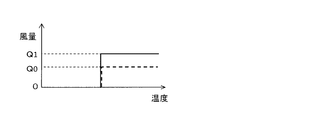
また、図3に示すように、回復動作中は、冷却ファンの風量を通常の風量Q0に比べて増加された風量Q1とするようにしてもよい。通常の風量Q0は、回復動作中か否かの情報(具体的には、回復スイッチ46のオンオフ状態)以外の情報、例えばそのときの蓄電装置26の充放電電力や温度の情報に基づき決定される風量である。回復動作中は、蓄電装置26への充電の機会が増え、充電電力が増加する。充放電電力に応じて風量が変更される場合、回復動作による充電電力の増加によって風量が増加するが、制御部38は、この増加以上に風量を増加し、今後のEVモードによる温度上昇に備える。蓄電装置26の温度に関しても同様であり、回復動作によって充電機会が増え温度が上昇するが、温度によって増加する風量以上に風量を増加して今後のEVモードによる温度上昇に備える。このように、回復スイッチ46がオン状態のときに、充放電電力や温度の情報に基づき決定される風量よりも風量を増加する制御は、蓄電装置26をより冷却する冷却増強制御である。冷却ファン36が動作しているとき(オンのとき)の風量は、固定値であってよい。また、風量は、そのときの蓄電装置26の充放電電力に応じて変化する値としてもよい。さらにまた、風量は、蓄電装置26の温度に応じて変化する値としてもよい。この風量を増加する制御は、前述の動作下限温度を低くする制御と共に実行されてもよい。
Further, as shown in FIG. 3, during the recovery operation, the air volume of the cooling fan may be set to an air volume Q1 that is increased compared to the normal air volume Q0. The normal air volume Q0 is determined on the basis of information other than information indicating whether or not the recovery operation is being performed (specifically, the on / off state of the recovery switch 46), for example, charging / discharging power and temperature information of the
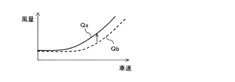
冷却ファン36の風量を車速に応じて変更するようにしてもよい。図4に示す曲線Qaは、回復動作中における冷却ファン36の風量を示しており、車速が高いとき風量が増加する特性を示している。制御部38は、車速センサ40の出力に基づき車速を取得し、その車速に対応して、曲線Qaに示されるあらかじめ定められた風量となるよう冷却ファン36を制御する。車速が低いときは走行音が小さいので、冷却ファン36の風量を落として騒音が目立たないようにする。一方、車速が高く走行音が大きいときには、走行音に紛れて冷却ファン36の騒音が目立たなくなるので風量を増加して冷却能力を高くする。車速に対する風量の制御は、図4に示すように連続的に増加する制御の他、段階的に増加するように制御してもよい。また、蓄電量の回復動作中において、通常時に比べて風量が増加するように制御することができる。図4において破線で表す曲線Qbが通常時の風量を示す。回復動作中は、風量増加による冷却ファン36の騒音よりも、冷却能力を優先する制御を行う。
The air volume of the cooling
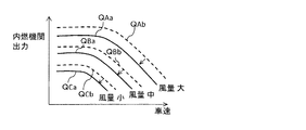
さらに、冷却ファン36の風量を車速と内燃機関の出力に基づき変更するようにしてもよい。内燃機関14の出力が高く、車速が高いときに風量を増加するようにできる。図5において、曲線QAa、曲線QBa、曲線QCaは、それぞれ風量大、中、小の特性を示している。制御部38は、車速センサ40の出力に基づき車速を取得する。また、制御部38は、運転者の要求および車両の状況に応じて内燃機関14の出力を制御しており、この制御指令に基づき内燃機関14の出力を取得する。制御部38は、取得した車速および内燃機関14の出力にあらかじめ対応づけられた風量となるよう冷却ファン36を制御する。図5から、同じ車速であれば、内燃機関14の出力が大きいと風量が大きくなり、同じ内燃機関出力であれば、車速が大きいと風量が大きくなることが理解できる。内燃機関の出力が大きくなれば、それに伴い内燃機関に起因する騒音も大きくなる。内燃機関14の出力が小さいときには、その騒音が小さいので、冷却ファン36の騒音が目立たないように風量を小さくする。内燃機関14の出力が大きくなれば、その騒音に紛れて冷却ファン36の騒音が目立たなくなるので風量を増加して冷却能力を高くする。風量の増加は、エンジン出力および車速に対して連続的に増加するようにすることも、段階的に増加するようにすることもできる。また、蓄電量の回復動作中において、通常時に比べて風量が増加するように制御することができる。図5において、破線で表す曲線QAb、曲線QBa、曲線QCaは、通常時の風量特性を表しており、それぞれ回復動作中の曲線QAa、曲線QBa、曲線QCaと等しい風量を表している。回復動作中は、風量増加による冷却ファン36の騒音よりも、冷却能力を有す優先する制御を行う。
Further, the air volume of the cooling
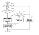
図6は、車両10における冷却ファン36の動作の設定に関するサブルーチンの処理フローの一例を示す図である。このフローは、制御部38により実行される。制御部38は、運転者が蓄電装置26の充電を要求しているかを判断する(S100)。充電要求の有無は、回復スイッチ46のオンオフ状態で判断することができ、オン状態であれば運転者の充電要求があると判断できる。回復スイッチ46がオン状態でなければ、通常の風量制御、すなわち運転者の充電要求以外の情報に基づき風量が決定される制御が継続される(S102)。回復スイッチ46がオン状態であれば、充電要求があったと判断され、続けてHVモードで走行中か(S104)、EVモードで走行中か(S106)が判断される。HVモードでも、EVモードでもない場合(例えば外部電源による充電時)、回復スイッチ46がオン状態であっても、通常の風量制御が行われる(S102)。ステップS104においてHVモードで走行中と判断されると、車速と内燃機関出力に基づき風量が設定される(S108)。例えば、図5に示すような車速および内燃機関出力と風量の対応関係を示す対応表データをあらかじめ記憶しておき、そのときの車速、内燃機関出力から対応する風量が設定される。ステップS108で風量を設定する際、車速と内燃機関の出力に関する情報に加え、通常の風力制御において風量設定に用いられる情報を用いてもよい。ステップS106においてEVモードで走行中と判断されると、車速に基づき風量が設定される(S110)。例えば、図4に示すような車速と風量の対応関係を示す対応表データをあらかじめ記憶しておき、そのときの車速に対応する風量が設定される。ステップS110で風量を設定する際、車速の情報に加え、通常の風力制御で風量設定に用いられる情報を用いてもよい。ステップS108またはステップS110で風量が設定されると、冷却ファンの動作下限温度が通常時に比べて低く設定される(S112)。図6において、ステップS108,S110の後、ステップS112が処理されるように表されているが、順序が逆であってもよい。変更された設定に基づき、冷却ファン36の動作が制御される。
FIG. 6 is a diagram illustrating an example of a processing flow of a subroutine regarding the setting of the operation of the cooling
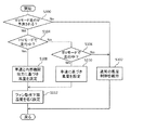
図7は、車両10における冷却ファン36の動作の設定に関するサブルーチンの処理フローの他の例を示す図である。この処理は、制御部38により実行される。制御部38は、運転者が蓄電装置26の充電を要求しているかを判断する(S200)。充電要求の有無は、回復スイッチ46のオンオフ状態で判断することができ、オン状態であれば運転者の充電要求があると判断できる。回復スイッチ46がオン状態でなければ、通常の風量制御、すなわち運転者の充電要求以外の情報に基づき風量が決定される制御が継続される(S202)。回復スイッチ46がオン状態であれば、充電要求があったと判断され、続けて内燃機関14が動作中であるかが判断される(S204)。ステップS204で内燃機関14が動作中と判断されると、車速と内燃機関出力に基づき風量が設定される(S208)。この風量の設定は、前述のステップS108と同様である。また、ステップS204で内燃機関が動作中でないと判断されると、車両が運行中かが判断される(S206)。車両が運行中でない場合(例えば外部電源による充電時)、回復スイッチ46がオン操作されていても、通常の風量制御が行われる(S202)。ステップS206で車両が運行中であれば、車速に基づき風量が設定される(S210)。この風量の設定は、前述のステップS110と同様である。また、冷却ファンの動作下限温度が通常時に比べて低く設定される(S212)。図7において、ステップS208,S210の後、ステップS212が処理されるように表されているが、順序が逆であってもよく、またステップS200の直後に処理されてもよい。変更された設定に基づき、冷却ファン36の動作が制御される。
FIG. 7 is a diagram illustrating another example of the subroutine processing flow regarding the setting of the operation of the cooling
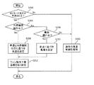
図8は、車両10における冷却ファン36の動作の設定に関するサブルーチンの処理フローの更に他の例を示す図である。この処理は、制御部38により実行される。この処理フローは、図6に示す処理フローのステップS100をステップS300に置き換えたものである。ステップS300の置換に伴い、ステップS302がステップS102に対して修正されている。その他のステップは、図6に示す処理フローと同様であり、同一の符号を付して説明を省略する。ステップ300において、制御部38は、EVモードによる走行がこのあと行われるかを予測する。EVモード走行の予測は、例えば回復スイッチ46の状態に基づいて予測することができる。回復スイッチ46がオン状態でなければ、通常の風力制御、すなわちEVモードによる走行の予測情報以外の情報に基づき風量が決定される制御が継続される(S302)。回復スイッチ46がオン状態とされている場合、運転者は、EVモード走行を今後行うために、現在蓄電装置26の充電を要求していると考えられる。したがって、回復スイッチ46のオン状態をもって、この後のEVモード走行を予測することができる。制御部38は、EVモードによる走行、すなわち回転電機のみによる走行が今後行われるかを予測する回転電機走行予測部として機能する。
FIG. 8 is a diagram showing still another example of the processing flow of the subroutine related to the setting of the operation of the cooling
また、EVモード走行の予測は他の手法で行われてもよい。例えば、運転者が過去に利用した経路を記憶し、その経路を走行したときにEVモード走行を行った区間があった場合、同じ経路を走行する際、EVモード走行の予測をすることができる。制御部38は、所定の経路に沿って誘導を行う経路誘導装置を含んでよい。制御部38は、走行した経路を記憶し、合わせてその経路においてEVモード走行された区間を記憶する。過去に走行したことがある経路が探索された場合、その経路においてEVモード走行された区間があると、その区間においてEVモード走行が行われると予測する。
Moreover, prediction of EV mode traveling may be performed by other methods. For example, if the driver memorizes a route used in the past and there is a section in which EV mode driving has been performed when traveling along the route, the EV mode driving can be predicted when traveling on the same route. . The
また、時間帯によりEVモード走行を予測してもよい。早朝や深夜においてEVモードが選択される可能性がある。例えば、住宅地に進入する場合には、車両走行音を低減するためにEVモードが選択されることがある。制御部38は、時計を備え、現在時刻が所定の時間帯であると今後EVモード走行があると予測する。所定の時間帯は、運転者等が任意に設定可能とすることもできる。
Moreover, you may estimate EV mode driving | running | working with a time slot | zone. There is a possibility that the EV mode is selected in the early morning or late at night. For example, when entering a residential area, the EV mode may be selected in order to reduce vehicle running noise. The
図9は、車両における冷却ファン36の動作の設定に関するサブルーチンの処理フローの更に他の例を示す図である。この処理は、制御部38により実行される。この処理フローは、図7に示す処理フローのステップS200をステップS400に置き換えたものである。ステップS400の置換に伴い、ステップS402がステップS202に対して修正されている。その他のステップは、図7に示す処理フローと同様であり、同一の符号を付して説明を省略する。また、ステップS400,S402は、図8のステップS300,S302と同様の処理を行うステップである。
FIG. 9 is a diagram showing still another example of the subroutine processing flow regarding the setting of the operation of the cooling
以上の説明においては、車両を使用する者が当該車両に搭乗し運転を行う場合を例に挙げた。しかし、車両を使用する者が当該車両以外のところにいてもよい。例えば、遠隔操作を行ってもよい。また、先行車両に追従して自動走行を行う自動追従走行(いわゆるかるがも走行)を行う車両においては、先行車両の運転者が追従車両の使用者となり、追従車両の蓄電装置の充電要求を行うことができる。 In the above description, a case where a person using a vehicle gets on the vehicle and performs driving is described as an example. However, the person using the vehicle may be in a place other than the vehicle. For example, remote operation may be performed. Further, in a vehicle that performs automatic follow-up traveling (so-called karugamo travel) that automatically follows the preceding vehicle, the driver of the preceding vehicle becomes a user of the following vehicle and requests charging of the power storage device of the following vehicle. Can do.
回復スイッチ46は、車室内、例えばインストルメントパネルに備えられた押しボタン、レバー等を利用したスイッチとできる。また、タッチパネル表示装置上に表示されたスイッチであってもよい。また、手動操作でなく、所定の音声が入力されたときに動作するスイッチであってもよい。前述の自動追従走行においては、先行車両からの無線通信によって動作するスイッチであってよい。
The
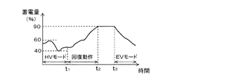
図10は、蓄電装置26の蓄電量の変化の様子を例示する図である。HVモードで走行中は、蓄電量は40〜60%の範囲に管理されている。回復スイッチ46がオン状態にされるなど、このあとのEVモード走行が予測されると(時点t1)、蓄電量の回復動作が実行される。回復動作中は、蓄電装置26への充電が促進されるように各原動機14,16,18が制御され、これに伴って蓄電量が増加する。蓄電量があらかじめ定められた上限値である90%に達すると(時点t2)、蓄電量がその状態で維持される。モード切替スイッチ44が操作されると(時点t3)、EVモードによる走行が開始される。EVモードにおいては、蓄電装置26から電力が供給され、蓄電量が減少する。
FIG. 10 is a diagram illustrating an example of a change in the amount of power stored in the
以上、本発明をプラグインハイブリッド車両に適用した場合を例に挙げて説明したが、本発明は、外部電源からの充電機能を有していないハイブリッド車両(以下、一般ハイブリッド車両と記す。)にも適用することができる。一般ハイブリッド車両の構成は、例えば、図1に示される構成から充電インレット30および充電装置34を除いたものである。一般ハイブリッド車両は、蓄電装置の蓄電量が中程度の範囲、例えば40〜60%の範囲となるように管理される。一般ハイブリッド車両であって、EVモードを運転者が選択できる場合、EVモード走行前に、通常の範囲を超えて蓄電量を増量しておくことでEVモードによる走行距離を伸ばすことができる。前述の回復スイッチ46と同様に、蓄電量の増量を要求するための増量スイッチを設けることができる。増量スイッチを運転者が操作することで、通常の蓄電量範囲の上限値より高い上限値(例えば80%)が設定され、この設定に応じて各原動機14,16,18が制御される。冷却ファン36の動作の設定に関する制御は、例えば図7,9に示されるフローに従って処理することができる。
The present invention has been described by taking the case where the present invention is applied to a plug-in hybrid vehicle as an example. However, the present invention is applied to a hybrid vehicle that does not have a charging function from an external power source (hereinafter referred to as a general hybrid vehicle). Can also be applied. The configuration of the general hybrid vehicle is obtained by, for example, excluding the charging
以下、本発明の好ましい態様の他の例を記す。
(1)車両駆動用の内燃機関および回転電機と、回転電機との間で電力の授受を行う蓄電装置と、蓄電装置を冷却するための冷却ファンとを有するハイブリッド車両の制御装置であって、
使用者の意思に基づく充電要求の有無を含む複数の情報に基づいて冷却ファンの動作を決定する冷却ファン制御部を有し、
冷却ファン制御部は、使用者の意思による充電要求がある場合は、使用者の意思に基づく充電要求の有無以外の情報に係る変数の値は同じであってかつ使用者の意思による充電要求がない場合に比べて、蓄電装置がより冷却されるよう冷却ファンの動作を制御する、
ハイブリッド車両の制御装置。
(2)車両駆動用の内燃機関および回転電機と、回転電機との間で電力の授受を行う蓄電装置と、蓄電装置を冷却するための冷却ファンとを有するハイブリッド車両の制御装置であって、
オン状態にされることにより蓄電装置への充電動作を要求する充電要求スイッチと、
充電要求スイッチのオンオフ状態を含む複数の情報に基づいて冷却ファンの動作を決定する冷却ファン制御部と、
を有し、
冷却ファン制御部は、充電要求スイッチがオン状態の場合は、充電スイッチのオンオフ状態以外の情報に係る変数の値は同じであってかつ充電要求スイッチがオフ状態の場合に比べて、蓄電装置がより冷却されるよう冷却ファンの動作を制御する、
ハイブリッド車両の制御装置。
(3)車両駆動用の内燃機関および回転電機と、回転電機との間で電力の授受を行う蓄電装置と、蓄電装置を冷却するための冷却ファンとを有するハイブリッド車両の制御装置であって、
回転電機のみによる走行が今後行われるかを予測する回転電機走行予測部と、
回転電機のみによる走行の予測を含む情報に基づいて冷却ファンの動作を決定する冷却ファン制御部と、
を有し、
冷却ファン制御部は、回転電機のみによる走行が予測される場合は、回転電機のみによる走行の予測以外の情報に係る変数の値は同じであってかつ回転電機のみによる走行が予測されない場合に比べて、蓄電装置がより冷却されるよう冷却ファンの動作を制御する、
ハイブリッド車両の制御装置。
Hereinafter, other examples of preferred embodiments of the present invention will be described.
(1) A control device for a hybrid vehicle having an internal combustion engine and a rotating electrical machine for driving a vehicle, a power storage device that transmits and receives power between the rotating electrical machine, and a cooling fan for cooling the power storage device,
A cooling fan control unit that determines the operation of the cooling fan based on a plurality of information including the presence or absence of a charging request based on the user's intention;
When there is a charging request based on the user's intention, the cooling fan control unit has the same value of the variable related to information other than the presence / absence of the charging request based on the user's intention and the charging request based on the user's intention Control the operation of the cooling fan so that the power storage device is cooled more than when there is no
Control device for hybrid vehicle.
(2) A control device for a hybrid vehicle having an internal combustion engine and a rotating electrical machine for driving a vehicle, a power storage device that transmits and receives power between the rotating electrical machine, and a cooling fan for cooling the power storage device,
A charge request switch for requesting a charging operation to the power storage device by being turned on; and
A cooling fan control unit that determines the operation of the cooling fan based on a plurality of information including the on / off state of the charge request switch;
Have
When the charge request switch is in the on state, the cooling fan control unit has the same value of the variable related to the information other than the on / off state of the charge switch, and the power storage device is compared with the case where the charge request switch is in the off state. Control the operation of the cooling fan to be more cooled,
Control device for hybrid vehicle.
(3) A control device for a hybrid vehicle having an internal combustion engine and a rotating electrical machine for driving a vehicle, a power storage device that transmits and receives power between the rotating electrical machine, and a cooling fan for cooling the power storage device,
A rotating electrical machine traveling prediction unit that predicts whether traveling using only the rotating electrical machine will be performed in the future;
A cooling fan control unit that determines the operation of the cooling fan based on information including prediction of traveling by only the rotating electrical machine;
Have
When the cooling fan control unit predicts traveling only by the rotating electrical machine, the value of the variable related to information other than the prediction of traveling only by the rotating electrical machine is the same, and the traveling by only the rotating electrical machine is not predicted. And controlling the operation of the cooling fan so that the power storage device is further cooled.
Control device for hybrid vehicle.
10 車両、12 動力装置、14 内燃機関(原動機)、16 第1回転電機(原動機)、18 第2回転電機(原動機)、26 蓄電装置、34 充電装置、36 冷却ファン、38 制御部(蓄電量増量指令部、冷却ファン制御部、車速取得部)、40 車速センサ、42 温度センサ、44 モード切替スイッチ、46 回復スイッチ(蓄電量増量スイッチ)。
DESCRIPTION OF
Claims (7)
蓄電装置の充放電電力と、車両運行中の使用者の意思に基づく充電要求の有無とに基づいて冷却ファンの動作を決定する冷却ファン制御部を有し、
冷却ファン制御部は、使用者の意思による充電要求がある場合は、同じ充放電電力であってかつ使用者の意思による充電要求がない場合に比べて、蓄電装置がより冷却されるよう冷却ファンの動作を制御することを特徴とするハイブリッド車両の制御装置。 A control apparatus for a hybrid vehicle having an internal combustion engine and a rotating electrical machine for driving a vehicle, a power storage device that transmits and receives power between the rotating electrical machine, and a cooling fan for cooling the power storage device,
A cooling fan control unit that determines the operation of the cooling fan based on the charge / discharge power of the power storage device and the presence or absence of a charge request based on the intention of the user during vehicle operation,
The cooling fan control unit is configured so that when there is a charging request at the user's intention, the cooling fan is more cooled than when the charging / discharging power is the same and there is no charging request at the user's intention. The control apparatus of the hybrid vehicle characterized by controlling operation | movement of this.
車両運行中において蓄電装置の蓄電量の増量動作を指令する蓄電量増量スイッチと、
蓄電装置の充放電電力と蓄電量増量スイッチのオンオフ状態とに基づいて冷却ファンの動作を決定する冷却ファン制御部と、
を有し、
冷却ファン制御部は、蓄電量増量スイッチがオン状態の場合は、同じ充放電電力であってかつ蓄電量増量スイッチがオフ状態の場合に比べて、蓄電装置がより冷却されるよう冷却ファンの動作を制御することを特徴とするハイブリッド車両の制御装置。 A control apparatus for a hybrid vehicle having an internal combustion engine and a rotating electrical machine for driving a vehicle, a power storage device that transmits and receives power between the rotating electrical machine, and a cooling fan for cooling the power storage device,
A storage amount increase switch for commanding an increase operation of the storage amount of the storage device during vehicle operation;
A cooling fan controller that determines the operation of the cooling fan based on the charge / discharge power of the power storage device and the on / off state of the storage amount increase switch;
Have
The cooling fan control unit operates the cooling fan so that the power storage device is cooled more when the power storage amount increase switch is in the on state than when the power storage amount increase switch is in the off state with the same charge / discharge power. A control apparatus for a hybrid vehicle, characterized by controlling the vehicle.
さらに、車両の速度を取得する車速取得部を有し、
冷却ファン制御部は、蓄電装置がより冷却されるよう冷却ファンの動作を制御しているときは、車速が高いときは、低いときに比べて冷却ファンの風量を増加させる、
ハイブリッド車両の制御装置。 A control device for a hybrid vehicle according to claim 3 or 4 ,
Furthermore, it has a vehicle speed acquisition unit that acquires the speed of the vehicle,
When the cooling fan control unit controls the operation of the cooling fan so that the power storage device is further cooled, the cooling fan control unit increases the air volume of the cooling fan when the vehicle speed is high compared to when the vehicle speed is low.
Control device for hybrid vehicle.
さらに、内燃機関の出力を取得する出力取得部を有し、
冷却ファン制御部は、蓄電装置がより冷却されるよう冷却ファンの動作を制御しているときは、内燃機関の出力が大きいときは、小さいときに比べて冷却ファンの風量を増加させる、
ハイブリッド車両の制御装置。 A control device for a hybrid vehicle according to any one of claims 3 to 5 ,
Furthermore, it has an output acquisition unit for acquiring the output of the internal combustion engine,
The cooling fan control unit increases the air volume of the cooling fan when the output of the internal combustion engine is large compared to when the output is small when controlling the operation of the cooling fan so that the power storage device is further cooled.
Control device for hybrid vehicle.
当該ハイブリッド車両は、回転電機のみにより車両を駆動するEVモードと、状況に応じて回転電機と内燃機関を使い分けて、または併用して車両を駆動するHVモードとを切り替えて走行可能であり、
冷却ファン制御部は、HVモードで走行しており、かつ蓄電装置がより冷却されるよう冷却ファンの動作を制御しているときは、内燃機関の出力が大きいときは、小さいときに比べて冷却ファンの風量を増加させる、
ハイブリッド車両の制御装置。 A control device for a hybrid vehicle according to any one of claims 3 to 5 ,
The hybrid vehicle can travel by switching between an EV mode in which the vehicle is driven only by the rotating electric machine, and an HV mode in which the rotating electric machine and the internal combustion engine are selectively used according to the situation, or the vehicle is driven in combination.
When the cooling fan control unit is running in the HV mode and is controlling the operation of the cooling fan so that the power storage device is further cooled, the cooling fan control unit is more cooled when the output of the internal combustion engine is larger than when it is small. Increase fan airflow,
Control device for hybrid vehicle.
Priority Applications (4)
| Application Number | Priority Date | Filing Date | Title |
|---|---|---|---|
| JP2014260843A JP6217618B2 (en) | 2014-12-24 | 2014-12-24 | Control device for hybrid vehicle |
| US14/972,558 US9758055B2 (en) | 2014-12-24 | 2015-12-17 | Control system for hybrid vehicle |
| DE102015122152.7A DE102015122152A1 (en) | 2014-12-24 | 2015-12-17 | Control system for a hybrid vehicle |
| CN201510963456.2A CN105730263B (en) | 2014-12-24 | 2015-12-21 | The control system of motor vehicle driven by mixed power |
Applications Claiming Priority (1)
| Application Number | Priority Date | Filing Date | Title |
|---|---|---|---|
| JP2014260843A JP6217618B2 (en) | 2014-12-24 | 2014-12-24 | Control device for hybrid vehicle |
Publications (2)
| Publication Number | Publication Date |
|---|---|
| JP2016120780A JP2016120780A (en) | 2016-07-07 |
| JP6217618B2 true JP6217618B2 (en) | 2017-10-25 |
Family
ID=56117063
Family Applications (1)
| Application Number | Title | Priority Date | Filing Date |
|---|---|---|---|
| JP2014260843A Active JP6217618B2 (en) | 2014-12-24 | 2014-12-24 | Control device for hybrid vehicle |
Country Status (4)
| Country | Link |
|---|---|
| US (1) | US9758055B2 (en) |
| JP (1) | JP6217618B2 (en) |
| CN (1) | CN105730263B (en) |
| DE (1) | DE102015122152A1 (en) |
Families Citing this family (13)
| Publication number | Priority date | Publication date | Assignee | Title |
|---|---|---|---|---|
| US10220832B2 (en) * | 2016-03-31 | 2019-03-05 | Honda Motor Co., Ltd. | Vehicle and method for controlling rotary electric machine |
| JP6372532B2 (en) * | 2016-09-05 | 2018-08-15 | トヨタ自動車株式会社 | Electric vehicle and control method of electric vehicle |
| FR3057998B1 (en) * | 2016-10-25 | 2018-11-30 | Peugeot Citroen Automobiles Sa | DEVICE AND METHOD FOR CONTROLLING THE TEMPERATURE OF A BATTERY BASED ON THE GRADIENT OF THE ELECTRICAL POWER DELIVERED |
| KR20180068391A (en) * | 2016-12-13 | 2018-06-22 | 현대자동차주식회사 | Cooling control method of battery management system in electric vehicle |
| KR102444125B1 (en) * | 2017-12-26 | 2022-09-16 | 주식회사 엘지에너지솔루션 | Apparatus and method for detecting battery module sweelling |
| JP6939606B2 (en) * | 2018-01-29 | 2021-09-22 | トヨタ自動車株式会社 | Hybrid vehicle |
| US10486689B2 (en) * | 2018-02-13 | 2019-11-26 | Ford Global Technologies, Llc | Systems and methods for reducing exterior noise during electrified vehicle operation |
| JP7227553B2 (en) * | 2018-08-27 | 2023-02-22 | 三菱自動車工業株式会社 | Battery cooling controller |
| KR102706229B1 (en) * | 2019-02-18 | 2024-09-12 | 현대자동차주식회사 | System and method for controlling thermal management apparatus of vehicle |
| FR3097172B1 (en) * | 2019-06-14 | 2021-08-13 | Psa Automobiles Sa | THERMAL MANAGEMENT PROCESS OF A BATTERY ALLOWING TO ADAPT THE THRESHOLD THRESHOLD OF THE THERMAL REGULATION DEPENDING ON THE TRANSFERRED ELECTRICAL POWER |
| CN110316006B (en) * | 2019-07-29 | 2022-06-14 | 重庆长安新能源汽车科技有限公司 | Cooling control system and method for charging vehicle-mounted equipment of electric vehicle |
| US20220355140A1 (en) * | 2021-05-05 | 2022-11-10 | Oshkosh Corporation | Operational modes for a driveline of an electrified fire fighting vehicle |
| EP4299357A1 (en) | 2022-06-29 | 2024-01-03 | Volvo Truck Corporation | Noise management in electric heavy vehicles |
Family Cites Families (15)
| Publication number | Priority date | Publication date | Assignee | Title |
|---|---|---|---|---|
| JP2001006651A (en) * | 1999-06-22 | 2001-01-12 | Sekisui Chem Co Ltd | Power storage unit |
| JP4442231B2 (en) * | 2004-01-19 | 2010-03-31 | トヨタ自動車株式会社 | Control device for cooling fan of power storage mechanism |
| JP4765298B2 (en) * | 2004-11-10 | 2011-09-07 | トヨタ自動車株式会社 | Battery cooling system |
| JP4254783B2 (en) * | 2006-01-27 | 2009-04-15 | トヨタ自動車株式会社 | Hybrid control device |
| JP4848780B2 (en) * | 2006-01-27 | 2011-12-28 | トヨタ自動車株式会社 | Control device for cooling fan |
| JP2007331737A (en) * | 2006-05-15 | 2007-12-27 | Toyota Motor Corp | Control device and control method for cooling fan for vehicle battery |
| JP4784409B2 (en) * | 2006-06-15 | 2011-10-05 | トヨタ自動車株式会社 | Vehicle battery cooling control system |
| JP5076378B2 (en) * | 2006-07-03 | 2012-11-21 | マツダ株式会社 | Battery temperature control device |
| JP4715708B2 (en) * | 2006-10-03 | 2011-07-06 | トヨタ自動車株式会社 | Electric vehicle and vehicle charging system |
| JP4715803B2 (en) * | 2007-05-07 | 2011-07-06 | トヨタ自動車株式会社 | Secondary battery cooling device |
| JP2010246320A (en) * | 2009-04-09 | 2010-10-28 | Fujitsu Ten Ltd | Controller and control method |
| JP2011121415A (en) * | 2009-12-08 | 2011-06-23 | Honda Motor Co Ltd | Hybrid vehicle |
| US20140081490A1 (en) * | 2012-09-14 | 2014-03-20 | Plug-In Conversions Corporation | System and method of converting a standard hybrid vehicle into a plug-in hybrid electric vehicle (phev) |
| JP2014189147A (en) * | 2013-03-27 | 2014-10-06 | Toyota Motor Corp | Hybrid vehicle |
| JP6003943B2 (en) * | 2014-04-28 | 2016-10-05 | トヨタ自動車株式会社 | Hybrid vehicle and control method of hybrid vehicle |
-
2014
- 2014-12-24 JP JP2014260843A patent/JP6217618B2/en active Active
-
2015
- 2015-12-17 US US14/972,558 patent/US9758055B2/en active Active
- 2015-12-17 DE DE102015122152.7A patent/DE102015122152A1/en active Pending
- 2015-12-21 CN CN201510963456.2A patent/CN105730263B/en active Active
Also Published As
| Publication number | Publication date |
|---|---|
| CN105730263A (en) | 2016-07-06 |
| JP2016120780A (en) | 2016-07-07 |
| US9758055B2 (en) | 2017-09-12 |
| CN105730263B (en) | 2018-02-27 |
| DE102015122152A1 (en) | 2016-06-30 |
| US20160185250A1 (en) | 2016-06-30 |
Similar Documents
| Publication | Publication Date | Title |
|---|---|---|
| JP6217618B2 (en) | Control device for hybrid vehicle | |
| JP6620126B2 (en) | Hybrid vehicle | |
| JP5839045B2 (en) | Hybrid car | |
| JP4254783B2 (en) | Hybrid control device | |
| EP2409871A2 (en) | Drive control device for electric vehicle, and electric vehicle | |
| CN111055691A (en) | Vehicle brake control device | |
| JP5125293B2 (en) | Control device for hybrid vehicle | |
| KR20190049143A (en) | Hybrid vehicle and method of changing operation mode for the same | |
| WO2012101735A1 (en) | Hybrid vehicle | |
| JP2011105293A (en) | Balancing control method for battery SOC of hybrid vehicle | |
| JP6725880B2 (en) | Control device for hybrid vehicle | |
| JP6119103B2 (en) | Control device for hybrid vehicle | |
| JP5333683B1 (en) | Hybrid car | |
| CN106965682A (en) | Regenerative brake control device | |
| WO2011121717A1 (en) | Vehicle control unit and vehicle control method | |
| JP2019085098A (en) | Hybrid vehicle and motor control method for the same | |
| JP6626519B2 (en) | Vehicle control device | |
| JPWO2018155083A1 (en) | Hybrid vehicle control device and hybrid vehicle | |
| US10399426B2 (en) | Control device for hybrid vehicle and control method | |
| JP4225293B2 (en) | Control device for vehicle driving motor | |
| JP2011182587A (en) | Charge control system | |
| JP2007185986A (en) | Vehicle control device | |
| JP2008132837A (en) | Hybrid vehicle | |
| JP5413530B2 (en) | Control device for electrically driven vehicle | |
| JP5261424B2 (en) | Control device for electrically driven vehicle |
Legal Events
| Date | Code | Title | Description |
|---|---|---|---|
| A131 | Notification of reasons for refusal |
Free format text: JAPANESE INTERMEDIATE CODE: A131 Effective date: 20161220 |
|
| A977 | Report on retrieval |
Free format text: JAPANESE INTERMEDIATE CODE: A971007 Effective date: 20161222 |
|
| A521 | Request for written amendment filed |
Free format text: JAPANESE INTERMEDIATE CODE: A523 Effective date: 20170215 |
|
| A131 | Notification of reasons for refusal |
Free format text: JAPANESE INTERMEDIATE CODE: A131 Effective date: 20170509 |
|
| A521 | Request for written amendment filed |
Free format text: JAPANESE INTERMEDIATE CODE: A523 Effective date: 20170703 |
|
| TRDD | Decision of grant or rejection written | ||
| A01 | Written decision to grant a patent or to grant a registration (utility model) |
Free format text: JAPANESE INTERMEDIATE CODE: A01 Effective date: 20170829 |
|
| A61 | First payment of annual fees (during grant procedure) |
Free format text: JAPANESE INTERMEDIATE CODE: A61 Effective date: 20170911 |
|
| R151 | Written notification of patent or utility model registration |
Ref document number: 6217618 Country of ref document: JP Free format text: JAPANESE INTERMEDIATE CODE: R151 |

