US10418603B2 - Circuit-substrate supporting device and a battery unit with the same - Google Patents
Circuit-substrate supporting device and a battery unit with the same Download PDFInfo
- Publication number
- US10418603B2 US10418603B2 US13/227,619 US201113227619A US10418603B2 US 10418603 B2 US10418603 B2 US 10418603B2 US 201113227619 A US201113227619 A US 201113227619A US 10418603 B2 US10418603 B2 US 10418603B2
- Authority
- US
- United States
- Prior art keywords
- substrate
- circuit substrate
- supporting
- circuit
- supporting members
- Prior art date
- Legal status (The legal status is an assumption and is not a legal conclusion. Google has not performed a legal analysis and makes no representation as to the accuracy of the status listed.)
- Expired - Fee Related, expires
Links
- 239000000758 substrate Substances 0.000 title claims abstract description 203
- 239000002184 metal Substances 0.000 description 10
- 238000005452 bending Methods 0.000 description 5
- 230000008901 benefit Effects 0.000 description 3
- 239000000470 constituent Substances 0.000 description 3
- 229910052739 hydrogen Inorganic materials 0.000 description 2
- 239000001257 hydrogen Substances 0.000 description 2
- 238000000465 moulding Methods 0.000 description 2
- HBBGRARXTFLTSG-UHFFFAOYSA-N Lithium ion Chemical compound [Li+] HBBGRARXTFLTSG-UHFFFAOYSA-N 0.000 description 1
- 239000002390 adhesive tape Substances 0.000 description 1
- 238000006073 displacement reaction Methods 0.000 description 1
- 239000011810 insulating material Substances 0.000 description 1
- 229910001416 lithium ion Inorganic materials 0.000 description 1
Images


Classifications
-
- H01M2/105—
-
- H—ELECTRICITY
- H01—ELECTRIC ELEMENTS
- H01M—PROCESSES OR MEANS, e.g. BATTERIES, FOR THE DIRECT CONVERSION OF CHEMICAL ENERGY INTO ELECTRICAL ENERGY
- H01M10/00—Secondary cells; Manufacture thereof
- H01M10/42—Methods or arrangements for servicing or maintenance of secondary cells or secondary half-cells
- H01M10/425—Structural combination with electronic components, e.g. electronic circuits integrated to the outside of the casing
-
- H—ELECTRICITY
- H01—ELECTRIC ELEMENTS
- H01M—PROCESSES OR MEANS, e.g. BATTERIES, FOR THE DIRECT CONVERSION OF CHEMICAL ENERGY INTO ELECTRICAL ENERGY
- H01M50/00—Constructional details or processes of manufacture of the non-active parts of electrochemical cells other than fuel cells, e.g. hybrid cells
- H01M50/20—Mountings; Secondary casings or frames; Racks, modules or packs; Suspension devices; Shock absorbers; Transport or carrying devices; Holders
- H01M50/204—Racks, modules or packs for multiple batteries or multiple cells
- H01M50/207—Racks, modules or packs for multiple batteries or multiple cells characterised by their shape
- H01M50/213—Racks, modules or packs for multiple batteries or multiple cells characterised by their shape adapted for cells having curved cross-section, e.g. round or elliptic
-
- H—ELECTRICITY
- H05—ELECTRIC TECHNIQUES NOT OTHERWISE PROVIDED FOR
- H05K—PRINTED CIRCUITS; CASINGS OR CONSTRUCTIONAL DETAILS OF ELECTRIC APPARATUS; MANUFACTURE OF ASSEMBLAGES OF ELECTRICAL COMPONENTS
- H05K7/00—Constructional details common to different types of electric apparatus
- H05K7/14—Mounting supporting structure in casing or on frame or rack
- H05K7/1417—Mounting supporting structure in casing or on frame or rack having securing means for mounting boards, plates or wiring boards
- H05K7/142—Spacers not being card guides
-
- Y—GENERAL TAGGING OF NEW TECHNOLOGICAL DEVELOPMENTS; GENERAL TAGGING OF CROSS-SECTIONAL TECHNOLOGIES SPANNING OVER SEVERAL SECTIONS OF THE IPC; TECHNICAL SUBJECTS COVERED BY FORMER USPC CROSS-REFERENCE ART COLLECTIONS [XRACs] AND DIGESTS
- Y02—TECHNOLOGIES OR APPLICATIONS FOR MITIGATION OR ADAPTATION AGAINST CLIMATE CHANGE
- Y02E—REDUCTION OF GREENHOUSE GAS [GHG] EMISSIONS, RELATED TO ENERGY GENERATION, TRANSMISSION OR DISTRIBUTION
- Y02E60/00—Enabling technologies; Technologies with a potential or indirect contribution to GHG emissions mitigation
- Y02E60/10—Energy storage using batteries
Definitions
- the present invention relates to a circuit-substrate supporting device that supports a circuit substrate by using a supporting member or the like, and a battery unit with the circuit-substrate supporting device.
- Well-known battery units include battery packs and the like in which batteries, such as lithium-ion secondary batteries and nickel-hydrogen secondary batteries, and a circuit substrate mounted with a battery protection circuit and the like are built into a housing as a unit.
- batteries such as lithium-ion secondary batteries and nickel-hydrogen secondary batteries
- a circuit substrate mounted with a battery protection circuit and the like are built into a housing as a unit.
- a circuit substrate is generally installed adjacent to batteries while being supported by a supporting member, such as a battery holder and a substrate holder (see Unexamined Japanese Patent Publication No. 10-12201 or 2006-164601).
- the circuit substrate is supported by a single supporting member that is larger than the outer shape of the circuit substrate (that is of a size encompassing the outer shape of the circuit substrate) in order to firmly support the circuit substrate.
- the supporting member of the circuit substrate is generally made by molding an insulating material such as plastic to prevent a short circuit of an electronic circuit constructed in the circuit substrate, and the like.
- an insulating material such as plastic to prevent a short circuit of an electronic circuit constructed in the circuit substrate, and the like.
- a supporting member like this might be bent and deformed by a remaining stress from the molding.
- a bending stress sometimes acts upon the circuit substrate due to the bent and deformed supporting member, which might cause a deformation such as warping, fracture or the like in the circuit substrate.
- An aspect of the present invention is directed to a circuit-substrate supporting device having a circuit substrate, a plurality of supporting members that are arranged at intervals in a longitudinal direction of the circuit substrate and support both longitudinal ends of the circuit substrate, and a housing onto which the supporting members are fixed.
- the supporting members are arranged at intervals in the longitudinal direction of the circuit substrate, and the circuit substrate is supported at the longitudinal ends by the supporting members. This enables a more drastic reduction in bending stress that is applied from the supporting members to the circuit substrate, as compared to conventional art using a single supporting member larger than an outer shape of the circuit substrate.
- the invention therefore reduces the possibility of deformation and fracture of the circuit substrate and the like in the circuit-substrate supporting device.
- FIG. 1 is a perspective view showing an appearance of a battery unit according to the invention
- FIG. 2 is an exploded perspective view showing the battery unit according to the invention.
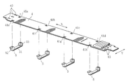
- FIG. 3 is an exploded perspective view of a main part of the battery unit, showing a part of the battery unit according to the invention
- FIG. 4 is a perspective view of a substrate holder
- FIG. 5 is a cross-sectional view of the battery unit according to the invention, taken along line A-A.
- the battery unit 10 of the present embodiment is an emergency power source of a so-called server (computer that provides functions, data, etc. to a client device in network).
- the battery unit 10 includes a circuit substrate 4 , four substrate holders 5 (supporting members) that are arranged at intervals in a longitudinal direction X of the circuit substrate 4 and support both longitudinal ends of the circuit substrate 4 , a housing cover 1 and a housing body 2 (housing) onto which the substrate holders 5 are fixed, and a plurality of batteries 3 supported in the housing body 2 and arranged adjacent to the circuit substrate 4 .
- the battery unit 10 includes a DC-DC converter mount section 20 . Built in the DC-DC converter mount section 20 is a DC-DC converter, not shown, that steps down the output voltage of the batteries 3 to rated voltage.
- the housing cover 1 is a long metal member having a substantially U-shaped cross section.
- a stepped portion 17 that is formed by doing bending work so as to provide a step in the longitudinal end.
- Four circular through-holes 11 are formed in the stepped portion 17 .
- a stepped portion 19 that is formed by doing bending work so as to provide a step in the lateral end.
- a female screw hole 12 is formed in the stepped portion 19 .
- two circular through-holes 13 and four circular through-holes 14 are formed in the housing cover 1 at predetermined positions.
- the housing body 2 is a substantially box-shaped member that opens in a section onto which the housing cover 1 is mounted.
- one longitudinal end 27 of the housing body 2 there are formed four circular through-holes 21 corresponding to the four circular through-holes 11 formed in the housing cover 1 .
- two female screw holes 23 are formed at positions corresponding to the two circular through-holes 13 of the housing cover 1 , and four female screw holes 24 at positions corresponding to the four circular through-holes 14 of the housing cover 1 .
- the batteries 3 are so-called nickel-hydrogen secondary batteries and situated inside the housing body 2 .
- the batteries 3 each have a diameter of 18 mm and a length of 67 mm.
- the output voltage of each of the batteries 3 is approximately 1.2 V.
- the battery unit 10 contains 54 batteries 3 arranged into three blocks of 18 serially-connected batteries including 3 strings of 6 batteries each. These three battery blocks are connected to each other in parallel.
- the total output voltage of the 54 batteries 3 is approximately 21.6 V that is obtained by multiplying 1.2 V by eighteen batteries. This total output voltage is stepped down by the DC-DC converter mount section 20 to a rated voltage of 12 V and is then outputted from the battery unit 10 .
- the batteries 3 are not limited to the foregoing in terms of kinds, size, number and the like.
- the DC-DC converter mount section 20 may be properly provided as needed, and is not an essential constituent of the invention.
- the circuit substrate 4 is mounted with a charge-discharge protection circuit of the batteries 3 and the like, and is situated adjacent to an upper face of the battery group formed of the batteries 3 .
- eight notches 41 a to 41 h are formed in the longitudinal ends at intervals in the longitudinal direction X.
- the notches 41 a to 41 h have an identical substantially rectangular shape, and are formed four each at intervals in the longitudinal ends of the circuit substrate 4 . More specifically, the notches 41 a to 41 d of the circuit substrate 4 are formed in one of the longitudinal ends at positions spaced away from each other at regular intervals in the longitudinal direction X, and the notches 41 e to 41 h in the other longitudinal end at positions spaced away from each other at regular intervals in the longitudinal direction X.
- the notches 41 a and 41 e are formed at the same positions as viewed in the longitudinal direction X (positions opposite to each other in the lateral direction Y) so as to have symmetrical shapes.
- the notches 41 b , 41 c and 41 d are formed at the same positions as the notches 41 f , 41 g and 41 h , respectively, as viewed in the longitudinal direction X (positions opposite to each other in the lateral direction Y) so as to have symmetrical shapes.
- pairs of symmetrical notches opposite to each other in the lateral direction Y are formed at positions spaced away from each other at regular intervals in the longitudinal direction X.
- the number, shape, layout and the like of the notches 41 a to 41 h are not limited to the above-mentioned aspect. Any aspect is possible as long as a plurality of notches are formed in the longitudinal ends of the circuit substrate 4 at intervals in the longitudinal direction X.
- the four substrate holders 5 serving as “supporting members” are members for supporting the circuit substrate 4 .
- the substrate holders 5 are arranged in positions corresponding to the respective notches 41 a to 41 h of the circuit substrate 4 and support the longitudinal ends of the circuit substrate 4 while being in engagement with the notches 41 a to 41 h . More specifically, the four substrate holders 5 are arranged in such positions that both end portions (first and second substrate-supporting portions 52 and 53 mentioned below) thereof are engaged with the respective pairs of the notches, that is, the pair of notches 41 a and 41 e , that of 41 b and 41 f , that of 41 c and 41 g , and that of 41 d and 41 h .
- the four substrate holders 5 are then screwed to the housing body 2 .
- the circuit substrate 4 is mounted on the housing body 2 by using the four substrate holders 5 .
- the substrate holder 5 is made up of a thin plate-shaped connecting plate 51 (base portion) that is elastically deformable, a first substrate-supporting portion 52 that is arranged at one end of the connecting plate 51 in a standing manner, and a second substrate-supporting portion 53 that is arranged at the other end of the connecting plate 51 in a standing manner.
- the substrate holders 5 is a member in which the connecting plate 51 , the first substrate-supporting portion 52 and the second substrate-supporting portion 53 are integrally molded into a substantially U-like shape.
- Each of the first and second substrate-supporting portions 52 and 53 has a substantially rectangular parallelepiped shape that is engageable with the notches 41 a to 41 h of the circuit substrate 4 .
- a metal screw bushing 54 provided with a female screw hole is embedded in the first substrate-supporting portion 52 of the substrate holder 5 from an upper surface 52 a side, and is fixed to be unturnable.
- a metal screw bushing 55 provided with a female screw hole is embedded in the second substrate-supporting portion 53 from an upper surface 53 a side, and is fixed to be unturnable.
- grooves 52 c and 53 c are formed in an inner surface 52 b of the first substrate-supporting portion 52 and an inner surface 53 b of the second substrate-supporting portion 53 , which face each other, so as to be engageable with the longitudinal ends at the corresponding pair of notches (the pair of notches 41 a and 41 e , that of 41 b and 41 f , that of 41 c and 41 g or that of 41 d and 41 h ) of the circuit substrate 4 .
- Supporting positions at which the circuit substrate 4 in the battery unit 10 is supported in a vertical direction Z (direction orthogonal to the longitudinal direction X and the lateral direction Y) are defined by the grooves 52 c and 53 c .
- each of the supporting positions at which the circuit substrate 4 in the battery unit 10 is supported in the vertical direction Z is defined by distance between the upper surface 52 a of the first substrate-supporting portion 52 in which the metal screw bushing 54 is embedded and the groove 52 c , and distance between the upper surface 53 a of the second substrate-supporting portion 53 in which the metal screw bushing 55 is embedded and the groove 53 c.
- a slant face 52 d slanting from the upper surface 52 a of the first substrate-supporting portion 52 into the inner surface 52 b and a slant face 53 d slanting from the upper face 53 a of the second substrate-supporting portion 53 into the inner surface 53 b .
- a lever portion 52 e is formed in the first substrate-supporting portion 52 so as to protrude in an outward direction.
- a protrusion 53 e (see FIG. 5 ) is formed in an outer surface of the second substrate-supporting portion 53 .
- the four substrate holders 5 are fitted to the circuit substrate 4 at the positions where the notches 41 a to 41 h are formed ( FIG. 3 ). Distance between the first and second substrate-supporting portions 52 and 53 of the substrate holder 5 can be widened by elastically deforming the connecting plate 51 .
- the substrate holder 5 can be fitted to the circuit substrate 4 by setting the circuit substrate 4 in between the first and second substrate-supporting portions 52 and 53 of the substrate holder 5 while elastically deforming the connecting plate 51 of the substrate holder 5 .
- the circuit substrate 4 is guided by the slat face 52 d formed in the first substrate-supporting portion 52 and the slat face 53 d in the second substrate-supporting portion 53 , and enters between the first and second substrate-supporting portions 52 and 53 of the substrate holder 5 . It is therefore possible to smoothly set the circuit substrate 4 in between the first and second substrate-supporting portions 52 and 53 with a smaller force.
- the distance between the first and second substrate-supporting portions 52 and 53 of the substrate holder 5 can be widened, for example, by pushing the lever portion 52 e formed in the first substrate-supporting portion 52 in a downward direction (direction shown by “Z 1 ”). In this way, the distance between the first and second substrate-supporting portions 52 and 53 of the substrate holder 5 can be easily widened by elastically deforming the connecting plate 51 with a slight force.
- the circuit substrate 4 to which the four substrate holders 5 are fitted is supported by the substrate holders 5 with the first and second substrate-supporting portions 52 and 53 of the substrate holders 5 engaged with the notches 41 a to 41 h , and with the longitudinal ends interfitted in the grooves 52 c and 53 c of the substrate holders 5 at the notches 41 a to 41 h ( FIG. 5 ).
- the 54 batteries 3 are loaded into the housing body 2 . More specifically, three battery blocks welded to a lead plate, not shown, made of a metal sheet are formed, each battery block containing 18 serially-connected batteries 3 including three batteries arranged in a width direction and six in a length direction adjacently to each other. These three battery blocks are loaded into the housing body 2 in layers.
- the three battery blocks may be integrally put together with adhesive tape or the like if desired.
- the circuit substrate 4 to which the four substrate holders 5 are fitted is placed at a position adjacent to an upper face side of the battery block located on top of the three battery blocks in layers with the connecting plates 51 of the substrate holders 5 intervening between the upper face of the battery block on top and the circuit substrate 4 ( FIG. 2 ).
- the protrusions 53 e of the four substrate holders 5 are interfitted in four positioning holes 29 formed at predetermined positions of the housing body 2 .
- the positioning holes 29 are formed at the positions corresponding to the protrusions 53 e of the four substrate holders 5 fitted to the circuit substrate 4 .
- the circuit substrate 4 is positioned relative to the housing body 2 as viewed in the longitudinal direction X, the lateral direction Y and the vertical direction Z by interfitting the protrusions 53 e of the four substrate holders 5 in the positioning holes 29 of the housing body 2 .
- the positions at which the circuit substrate 4 is supported in the vertical direction Z in the battery unit 10 are defined by the grooves 52 c and 53 c of the substrate holders 5 .
- Distance between the batteries 3 and the circuit substrate 4 in the vertical direction Z is then defined to be predetermined distance by the grooves 52 c and 53 c of the substrate holders 5 . This reduces the possibility that the circuit substrate 4 will contact the batteries 3 to cause a short circuit and the like.
- Distance from the housing cover 1 and the housing body 2 to the circuit substrate 4 in the vertical direction Z is also defined to be predetermined distance by the grooves 52 c and 53 c of the substrate holders 5 . This reduces the possibility that the circuit substrate 4 will contact the housing cover 1 or the housing body 2 to cause a short circuit and the like.
- the positions of the grooves 52 c and 53 c of the substrate holder 5 are determined in consideration of the mounting height of electronic components mounted on the circuit substrate 4 . This reduces the possibility that the electronic components mounted on the circuit substrate 4 will interfere with the housing cover 1 , the housing body 2 or the batteries 3 . Further preferably, an insulating sheet or the like, not shown, is provided, for example, between the substrate holders 5 and the batteries 3 , and also between the upper surface of the circuit substrate 4 and the housing cover 1 , as needed.
- Protrusions, not shown, formed in both lateral ends of the lead plate, not shown, of each of the battery blocks are inserted into three longitudinally elongated holes 42 formed in one lateral end of the circuit substrate 4 and three laterally elongated holes 43 formed in the other lateral end.
- the protrusions of the lead plate are then soldered and fixed onto the circuit substrate 4 .
- the housing cover 1 is fitted to a predetermined position of the housing body 2 .
- the housing cover 1 is fitted to the housing body 2 with a longitudinal end 18 of the housing cover 1 in contact with a stepped portion 28 of the housing body 2 , and with a longitudinal end 27 of the housing body 2 in contact with a stepped portion 17 of the housing cover 1 ( FIGS. 1 and 5 ).
- the circuit substrate 4 is screwed to the housing body 2 with four male screws 25 .
- the male screws 25 are inserted into four circular through-holes 11 of the housing cover 1 and four circular through-holes 21 of the housing body 2 .
- the male screws 25 are screwed into the female screw holes formed in the metal screw bushings 55 of the second substrate-supporting portions 53 of the substrate holders 5 , thereby fastening the housing cover 1 and the housing body 2 together.
- the circuit substrate 4 is thus fixed to the housing body 2 with the four substrate holders 5 intervening therebetween ( FIG. 5 ).
- the metal screw bushings 54 provided to the first substrate-supporting portions 52 of the substrate holders 5 are not used in the present embodiment. It is also possible to provide four through-holes to the housing cover 1 to be located at positions corresponding to the female screw holes of the metal screw bushings 54 , and screw the male screws into the female screw holes of the metal screw bushings 54 through the through-holes. By so doing, the four substrate holders 5 are screwed to the housing body 2 at both the ends, allowing the circuit substrate 4 to be more stably fitted to the housing body 2 .
- the housing cover 1 is then screwed to the housing body 2 by using two male screws 15 , four male screws 16 and one male screw 26 .
- the male screw 26 is inserted into the circular through-hole 22 of the housing body 2 and is then screwed into the female screw hole 12 of the housing cover 1 .
- the male screws 15 are inserted into the two circular through-holes 13 of the housing cover 1 and are then screwed into the female screw holes 23 of the housing body 2 .
- the male screws 16 are inserted into the four circular through-holes 14 of the housing cover 1 and are then screwed into the female screw holes 24 of the housing body 2 .
- the substrate holders 5 are arranged at intervals in the longitudinal direction X of the circuit substrate 4 , and the circuit substrate 4 is supported by the substrate holders 5 at the longitudinal ends thereof. This more drastically reduces bending stress that is applied from the substrate holders 5 to the circuit substrate 4 than in conventional art. According to the invention, therefore, the possibility of deformation and fracture of the circuit substrate 4 and the like can be reduced.
- the battery unit 10 of the invention is so configured that the circuit substrate 4 is supported by the substrate holders 5 arranged at intervals in the longitudinal direction X of the circuit substrate 4 , it is possible to drastically reduce an area in which the components mounted on the circuit substrate 4 and the substrate holders 5 interfere with each other. In short, components can be mounted on both sides of the circuit substrate 4 to be located between each two adjacent substrate holders 5 arranged at intervals. According to the invention, therefore, freedom for component layout on the circuit substrate 4 and that for the design of circuit patterns are vastly improved.
- the battery unit 10 of the invention is so configured that, as in the embodiment, the circuit substrate 4 is supported while a plurality of notches (notches 41 a to 41 h ) formed in the circuit substrate 4 are engaged with the substrate holders 5 .
- a plurality of notches (notches 41 a to 41 h ) formed in the circuit substrate 4 are engaged with the substrate holders 5 .
- the above configuration allows the circuit substrate 4 to be more firmly supported as positioned.
- the circuit substrate 4 is locked by the four substrate holders 5 held in engagement with the notches 41 a to 41 h of the circuit substrate 4 , reducing the possibility of displacement of the circuit substrate 4 , which is attributable to vibration or the like.
- each of the substrate holders 5 of the battery unit 10 of the invention includes, as in the embodiment, the elastically deformable connecting plate 51 and two substrate-supporting portions (first and second substrate-supporting portions 52 and 53 ) that are formed in a standing manner in both ends of the connecting plate 51 and provided in the inner surfaces with grooves in which the longitudinal ends of the circuit substrate 4 can be interfitted.
- first and second substrate-supporting portions 52 and 53 are formed in a standing manner in both ends of the connecting plate 51 and provided in the inner surfaces with grooves in which the longitudinal ends of the circuit substrate 4 can be interfitted.
- the “circuit-substrate supporting device” of the invention described above is not particularly limited to this.
- the invention can be applied to the supporting structure of a main substrate in an electronic device provided with a microcomputer control circuit, the supporting structure of a sub-substrate mounted with an electronic switch and LED, etc.
- the invention can be applied to any electronic device including a circuit substrate and can provide the operation and advantages thereof at the same time.
- the embodiment uses the battery unit serving as an emergency power source of a server, but the battery unit is not limited to this.
- the invention can be applied to any battery unit with a built-in circuit substrate and built-in batteries, including battery units for office automation equipment, such as desktop personal computers, printers, fax machines and copier complex machines, battery packs for mobile devices, such as notebook computers, laptop personal computers, and digital cameras, and can provide the operation and advantages thereof at the same time.
- battery units for office automation equipment such as desktop personal computers, printers, fax machines and copier complex machines
- battery packs for mobile devices such as notebook computers, laptop personal computers, and digital cameras
Abstract
Description
Claims (7)
Applications Claiming Priority (2)
| Application Number | Priority Date | Filing Date | Title |
|---|---|---|---|
| JP2010207966A JP5574422B2 (en) | 2010-09-16 | 2010-09-16 | Circuit board support device and battery unit including the circuit board support device |
| JP2010-207966 | 2010-09-16 |
Publications (2)
| Publication Number | Publication Date |
|---|---|
| US20120070699A1 US20120070699A1 (en) | 2012-03-22 |
| US10418603B2 true US10418603B2 (en) | 2019-09-17 |
Family
ID=44674449
Family Applications (1)
| Application Number | Title | Priority Date | Filing Date |
|---|---|---|---|
| US13/227,619 Expired - Fee Related US10418603B2 (en) | 2010-09-16 | 2011-09-08 | Circuit-substrate supporting device and a battery unit with the same |
Country Status (4)
| Country | Link |
|---|---|
| US (1) | US10418603B2 (en) |
| EP (1) | EP2432046B1 (en) |
| JP (1) | JP5574422B2 (en) |
| CN (1) | CN102437294B (en) |
Families Citing this family (7)
| Publication number | Priority date | Publication date | Assignee | Title |
|---|---|---|---|---|
| JP5716637B2 (en) * | 2011-11-04 | 2015-05-13 | 住友電気工業株式会社 | Semiconductor module and method for manufacturing semiconductor module |
| CA2901318A1 (en) * | 2013-02-27 | 2014-09-04 | Ioxus, Inc. | Energy storage device assembly |
| US9899643B2 (en) | 2013-02-27 | 2018-02-20 | Ioxus, Inc. | Energy storage device assembly |
| US9738976B2 (en) | 2013-02-27 | 2017-08-22 | Ioxus, Inc. | Energy storage device assembly |
| US9892868B2 (en) | 2013-06-21 | 2018-02-13 | Ioxus, Inc. | Energy storage device assembly |
| KR102210889B1 (en) * | 2016-08-02 | 2021-02-02 | 삼성에스디아이 주식회사 | Battery module |
| KR102519444B1 (en) * | 2020-11-02 | 2023-04-07 | 삼성에스디아이 주식회사 | Battery pack |
Citations (14)
| Publication number | Priority date | Publication date | Assignee | Title |
|---|---|---|---|---|
| US4400858A (en) | 1981-01-30 | 1983-08-30 | Tele-Drill Inc, | Heat sink/retainer clip for a downhole electronics package of a measurements-while-drilling telemetry system |
| JPH0442042A (en) | 1990-06-08 | 1992-02-12 | Schlumberger Overseas Sa | Device and method of analyzing composition of stratum fluid |
| JPH0451187A (en) | 1990-06-18 | 1992-02-19 | Fujitsu Ltd | Liquid crystal display device |
| US5424725A (en) | 1993-02-25 | 1995-06-13 | Motorola, Inc. | Battery retainer with integral mechanical shock isolation |
| JPH1012201A (en) | 1996-06-20 | 1998-01-16 | Sanyo Electric Co Ltd | Pack battery with built-in printed board |
| CN1229279A (en) | 1998-03-13 | 1999-09-22 | 鸿海精密工业股份有限公司 | Fastening device |
| JP2000133224A (en) | 1998-10-29 | 2000-05-12 | Sanyo Electric Co Ltd | Pack battery |
| US6233156B1 (en) * | 1999-04-16 | 2001-05-15 | Hon Hai Precision Ind. Co., Ltd. | Circuit board retainer |
| JP2006164601A (en) | 2004-12-03 | 2006-06-22 | Sanyo Electric Co Ltd | Battery pack |
| US20060215374A1 (en) | 2005-03-28 | 2006-09-28 | Inventec Corporation | Circuit board clamping device |
| CN101268569A (en) | 2005-09-20 | 2008-09-17 | 麦太保有限公司 | Accumulator group and handheld electric tool |
| US20100165582A1 (en) | 2008-03-04 | 2010-07-01 | Infineon Technologies Ag | Power semiconductor module system |
| US20100178536A1 (en) * | 2009-01-09 | 2010-07-15 | Samsung Sdi Co., Ltd. | Battery pack |
| US20110003196A1 (en) * | 2009-07-06 | 2011-01-06 | Samsung Sdi Co., Ltd. | Battery pack |
Family Cites Families (2)
| Publication number | Priority date | Publication date | Assignee | Title |
|---|---|---|---|---|
| JPH0442042U (en) * | 1990-08-07 | 1992-04-09 | ||
| JPH0744055Y2 (en) * | 1990-09-03 | 1995-10-09 | 池田電機株式会社 | Printed circuit board holding structure |
-
2010
- 2010-09-16 JP JP2010207966A patent/JP5574422B2/en not_active Expired - Fee Related
-
2011
- 2011-09-06 EP EP11180260.9A patent/EP2432046B1/en not_active Not-in-force
- 2011-09-08 US US13/227,619 patent/US10418603B2/en not_active Expired - Fee Related
- 2011-09-15 CN CN201110285338.2A patent/CN102437294B/en not_active Expired - Fee Related
Patent Citations (15)
| Publication number | Priority date | Publication date | Assignee | Title |
|---|---|---|---|---|
| US4400858A (en) | 1981-01-30 | 1983-08-30 | Tele-Drill Inc, | Heat sink/retainer clip for a downhole electronics package of a measurements-while-drilling telemetry system |
| JPH0442042A (en) | 1990-06-08 | 1992-02-12 | Schlumberger Overseas Sa | Device and method of analyzing composition of stratum fluid |
| JPH0451187A (en) | 1990-06-18 | 1992-02-19 | Fujitsu Ltd | Liquid crystal display device |
| US5424725A (en) | 1993-02-25 | 1995-06-13 | Motorola, Inc. | Battery retainer with integral mechanical shock isolation |
| JPH1012201A (en) | 1996-06-20 | 1998-01-16 | Sanyo Electric Co Ltd | Pack battery with built-in printed board |
| CN1229279A (en) | 1998-03-13 | 1999-09-22 | 鸿海精密工业股份有限公司 | Fastening device |
| JP2000133224A (en) | 1998-10-29 | 2000-05-12 | Sanyo Electric Co Ltd | Pack battery |
| US6233156B1 (en) * | 1999-04-16 | 2001-05-15 | Hon Hai Precision Ind. Co., Ltd. | Circuit board retainer |
| JP2006164601A (en) | 2004-12-03 | 2006-06-22 | Sanyo Electric Co Ltd | Battery pack |
| US20060215374A1 (en) | 2005-03-28 | 2006-09-28 | Inventec Corporation | Circuit board clamping device |
| CN101268569A (en) | 2005-09-20 | 2008-09-17 | 麦太保有限公司 | Accumulator group and handheld electric tool |
| US20080254356A1 (en) * | 2005-09-20 | 2008-10-16 | Metabowerke Gmbh | Rechargeable Battery Pack and Electrical Hand Tool Device |
| US20100165582A1 (en) | 2008-03-04 | 2010-07-01 | Infineon Technologies Ag | Power semiconductor module system |
| US20100178536A1 (en) * | 2009-01-09 | 2010-07-15 | Samsung Sdi Co., Ltd. | Battery pack |
| US20110003196A1 (en) * | 2009-07-06 | 2011-01-06 | Samsung Sdi Co., Ltd. | Battery pack |
Non-Patent Citations (3)
| Title |
|---|
| Chinese Office Action issued by the Chinese Patent Office in corresponding Chinese Patent Application No. 201110285338.2 and dated Aug. 26, 2014. |
| Extended Search Report for European Patent Application No. 11180260.9-1227, dated Jan. 26, 2012. |
| Office Action issued in EP 11 180 269, dated Apr. 30, 2014. |
Also Published As
| Publication number | Publication date |
|---|---|
| CN102437294B (en) | 2015-07-08 |
| JP2012064766A (en) | 2012-03-29 |
| CN102437294A (en) | 2012-05-02 |
| EP2432046A1 (en) | 2012-03-21 |
| JP5574422B2 (en) | 2014-08-20 |
| US20120070699A1 (en) | 2012-03-22 |
| EP2432046B1 (en) | 2017-03-15 |
Similar Documents
| Publication | Publication Date | Title |
|---|---|---|
| US10418603B2 (en) | Circuit-substrate supporting device and a battery unit with the same | |
| US11820286B2 (en) | Light-emitting device | |
| CN100446306C (en) | Rechargeable battery module | |
| RU2508577C2 (en) | Packages of accumulator batteries | |
| EP1225646A1 (en) | Assembled battery unit and manufacturing method thereof | |
| JP5714716B2 (en) | Power control device | |
| US20150270526A1 (en) | Battery pack and device for connecting tabs of battery cells in the same | |
| US9801298B2 (en) | Composite module | |
| US20090170577A1 (en) | Battery cover assembly | |
| US7724540B1 (en) | Spacer for circuit boards | |
| CN110603663A (en) | Battery module and battery module assembly | |
| US9461338B2 (en) | Battery assembly | |
| US11026349B2 (en) | Telecommunications enclosure with separate heat sink assembly | |
| JP6062203B2 (en) | Battery pack | |
| US20130017699A1 (en) | Power supply device and power supply system | |
| JP2010038920A (en) | Backplate and backplate-equipped socket apparatus | |
| EP3490024B1 (en) | Battery pack | |
| US9538679B1 (en) | Power transmission structure of power supply unit | |
| US20130011718A1 (en) | Battery module | |
| WO2007013262A1 (en) | Terminal box for solar cell module | |
| US10910160B2 (en) | Capacitor module having rounded rectangular prism-shaped capacitor elements | |
| US8795866B2 (en) | Battery cover assembly for portable electronic device | |
| JP2021061200A (en) | Battery fixing member | |
| US11114787B2 (en) | Terminal for connector mounted to printed circuit board and connector supporting said terminal | |
| KR101646826B1 (en) | Curved PCM |
Legal Events
| Date | Code | Title | Description |
|---|---|---|---|
| AS | Assignment |
Owner name: FDK TWICELL CO., LTD., JAPAN Free format text: ASSIGNMENT OF ASSIGNORS INTEREST;ASSIGNORS:IMAIZUMI, MINORU;YAMASHITA, MASANORI;REEL/FRAME:027210/0720 Effective date: 20110914 |
|
| AS | Assignment |
Owner name: FDK CORPORATION, JAPAN Free format text: MERGER AND CHANGE OF NAME;ASSIGNORS:FDK TWICELL CO., LTD.;FDK CORPORATION;REEL/FRAME:034842/0772 Effective date: 20141201 |
|
| AS | Assignment |
Owner name: FDK CORPORATION, JAPAN Free format text: CORRECTIVE ASSIGNMENT TO CORRECT THE ADDRESS OF THE RECEIVING PARTY PREVIOUSLY RECORDED AT REEL: 034842 FRAME: 0772. ASSIGNOR(S) HEREBY CONFIRMS THE ASSIGNMENT;ASSIGNOR:FDK TWICELL CO., LTD.;REEL/FRAME:036827/0058 Effective date: 20141201 |
|
| AS | Assignment |
Owner name: FDK CORPORATION, JAPAN Free format text: CHANGE OF ADDRESS;ASSIGNOR:FDK CORPORATION;REEL/FRAME:037952/0896 Effective date: 20150316 |
|
| STPP | Information on status: patent application and granting procedure in general |
Free format text: FINAL REJECTION MAILED |
|
| STPP | Information on status: patent application and granting procedure in general |
Free format text: RESPONSE AFTER FINAL ACTION FORWARDED TO EXAMINER |
|
| STPP | Information on status: patent application and granting procedure in general |
Free format text: NOTICE OF ALLOWANCE MAILED -- APPLICATION RECEIVED IN OFFICE OF PUBLICATIONS |
|
| STPP | Information on status: patent application and granting procedure in general |
Free format text: PUBLICATIONS -- ISSUE FEE PAYMENT VERIFIED |
|
| STCF | Information on status: patent grant |
Free format text: PATENTED CASE |
|
| FEPP | Fee payment procedure |
Free format text: MAINTENANCE FEE REMINDER MAILED (ORIGINAL EVENT CODE: REM.); ENTITY STATUS OF PATENT OWNER: LARGE ENTITY |
|
| LAPS | Lapse for failure to pay maintenance fees |
Free format text: PATENT EXPIRED FOR FAILURE TO PAY MAINTENANCE FEES (ORIGINAL EVENT CODE: EXP.); ENTITY STATUS OF PATENT OWNER: LARGE ENTITY |
|
| STCH | Information on status: patent discontinuation |
Free format text: PATENT EXPIRED DUE TO NONPAYMENT OF MAINTENANCE FEES UNDER 37 CFR 1.362 |
|
| FP | Lapsed due to failure to pay maintenance fee |
Effective date: 20230917 |