US1036280A - Ash-sifter. - Google Patents
Ash-sifter. Download PDFInfo
- Publication number
- US1036280A US1036280A US54101110A US1910541011A US1036280A US 1036280 A US1036280 A US 1036280A US 54101110 A US54101110 A US 54101110A US 1910541011 A US1910541011 A US 1910541011A US 1036280 A US1036280 A US 1036280A
- Authority
- US
- United States
- Prior art keywords
- ash
- sieve
- hopper
- sifter
- casing
- Prior art date
- Legal status (The legal status is an assumption and is not a legal conclusion. Google has not performed a legal analysis and makes no representation as to the accuracy of the status listed.)
- Expired - Lifetime
Links
- 239000002956 ash Substances 0.000 description 21
- 235000002918 Fraxinus excelsior Nutrition 0.000 description 10
- 238000010276 construction Methods 0.000 description 4
- 229910052751 metal Inorganic materials 0.000 description 3
- 239000002184 metal Substances 0.000 description 3
- 230000015572 biosynthetic process Effects 0.000 description 2
- 238000004519 manufacturing process Methods 0.000 description 2
- 238000005452 bending Methods 0.000 description 1
- 239000003818 cinder Substances 0.000 description 1
- 229910001385 heavy metal Inorganic materials 0.000 description 1
- 235000000396 iron Nutrition 0.000 description 1
- 238000000034 method Methods 0.000 description 1
- 238000005476 soldering Methods 0.000 description 1
- 238000003466 welding Methods 0.000 description 1
Images
Classifications
-
- F—MECHANICAL ENGINEERING; LIGHTING; HEATING; WEAPONS; BLASTING
- F24—HEATING; RANGES; VENTILATING
- F24B—DOMESTIC STOVES OR RANGES FOR SOLID FUELS; IMPLEMENTS FOR USE IN CONNECTION WITH STOVES OR RANGES
- F24B15/00—Implements for use in connection with stoves or ranges
- F24B15/007—Ash-sifters
-
- B—PERFORMING OPERATIONS; TRANSPORTING
- B07—SEPARATING SOLIDS FROM SOLIDS; SORTING
- B07B—SEPARATING SOLIDS FROM SOLIDS BY SIEVING, SCREENING, SIFTING OR BY USING GAS CURRENTS; SEPARATING BY OTHER DRY METHODS APPLICABLE TO BULK MATERIAL, e.g. LOOSE ARTICLES FIT TO BE HANDLED LIKE BULK MATERIAL
- B07B1/00—Sieving, screening, sifting, or sorting solid materials using networks, gratings, grids, or the like
- B07B1/18—Drum screens
- B07B1/22—Revolving drums
- B07B1/24—Revolving drums with fixed or moving interior agitators
Definitions
- Invew%0 T Z0315 many LOUIS LIBBMAN, OF EVERETT, MASSACHUSETTS, ASSIGNOR TO GEM MANUFACTURING COMPANY, OF CHELSEA, MASSACHUSETTS, A CORPORATION OF MASSACHUSETTS.
- -My invention is an ash sifter, having for its object economy, simplicity and convenience of construction, and convenience of operation.
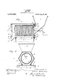
- Figure 1 is a central vertical longitudinal sectional view
- Fig. 2 is a cross-sectional view taken approximately. on the line 2-2, Fig. 1.
- My ash sifter is intended for usewith a usual ash receptacle 1, and for this purpose is provided with a correspondingly shape cover 2 to fit down over the open, top of the ash receptacle.
- the ash sifter consists, broadly speaking, of an outer casing or jacket 3, an inner longitudinally extending sieve or rotary screen 4, a hopper 5 at one end, an outlet 6 for the cinders at the opposite end, and an intervening outlet or ashes-opening 7 in the ash-receptacle cover beneath the sieve 4, and one of the leading features of my invention resides in providing the outer casing or jacket with opposite inclined walls 8 on its lower side, which have a large number of advantages, one being that they direct the ashes positively and certainly lnto the receptacle and prevent any possibility of the ashes lodging as in the case of a cylindrical casing, and another advantage being that the hexagonal or other polygonal shape in cross-section is much more economical'in materialand process of manufacture and permits an openbottom
- the casing consists of a piece of sheet metal bent around to con-- st-itute five sides of the casing and upturned at 9 at its opposite longitudinal edges, which fit into over-turned flanges 10 formed at the edges of the opening 7 in the cover, the result being that the casing has its upturned flanges or edges 9 simply inserted in the cooperating flanges 10 of the cover 2 and then the parts are slid forward into tne position shown in Fig. 1.. with the result that. the ash sifter casing is thereby mounted in correct position and yet is practically immovable and heldpermanently as desired.
- the opposite ends 11, 12, of the casing fit tightly in the casing and each is set in or provided with a deep flange 13, 14, for giving strength and making a tight joint.
- the end 12 has a bearing 15'for the project-ing end 16 of the sieve carrier wire 17, which is herein shown as bent spirally and slipped tightly into'the cylindrical sieve 4 (and if necessary soldered, although this is not usually necessary).
- the handle end 18 of the wire or rod 17 is journaled at 19 in the hopper 5, said hopper being permanently united for example, by electric welding with dthe end 11.
- a special feature of my invention resides in the formation of the connection between the hopper 5 and the end 11.
- the throat portion of the hopper extends inwardly beyond the face of the end 11 as indicated at 20' and thence has a circular vertical flange 21 connecting with the horizontal shoulder 22 of the end 11.
- This construction gives great bracing strength to resist the tendency of the hopper when heavily loaded to buckle or bend outward, deform the end 11, tend to make the sieve bind, and disarrange an distort the sifter' generally.
- the hoop closes the holes at the endof the sieve so that the ashes can notescape from the sieve until they get over the opening 7 and the rolled, over edge 24 of the hoop serves to keep the .joint tight and, therefore keep the ashes in the sieve.
- the flange 21 constitutes at its lower side a dropfor the ashes so that there is'no' tendency of the ashes to lodge in the hopper but they are practically compelled to drop from the throat of the hopper directly into the sieve.
- the down-turned end of -the handle 18 is on the opposite side from the adjacent radially connecting portion 25 of the rod 17 at the end of the sieve, so that-thereby the sieve naturally assumes the position shown in Fig.
- ash-Sifter comprising a receptaclecover, havin arectangular opening therein, the longitudmal edges of which are bent upwardly and then downwardly to form guides, a casing, polygonal in vertical crosssection and havin g lts bottom side removed to form an opening corresponding to the opening in said receptacle cover,the longitudinal edges of said casingiopenmg being bent outwardly and upwardly to' in said guides, whereby no obstructlonis fit slidably,
- a casing having an mounted in said open inlet end, a hopper terminating in a flanged end: removably fitting said casing,
- a'rotary sieve inclosin said internal shoulder, a circular radial ange extending from said internal shoulder toward the axis of said sieve and verging at vits inner edge outwardlyvinto said hopper, thereby lower side from the hopper into said sieve for directing the ashes beyond the joint betwe'en the sieve and the removable end and providing strength and bracing construction for the removable end and hopper.
Landscapes
- Engineering & Computer Science (AREA)
- Chemical & Material Sciences (AREA)
- Combustion & Propulsion (AREA)
- Mechanical Engineering (AREA)
- General Engineering & Computer Science (AREA)
- Combined Means For Separation Of Solids (AREA)
Description
L. LIBBMAN.
ASH SIFTBR.
APPLICATION FILED JAN. 31, 1910.
Pateilted Aug. 20, 1912.
Invew%0 T Z0315 many LOUIS LIBBMAN, OF EVERETT, MASSACHUSETTS, ASSIGNOR TO GEM MANUFACTURING COMPANY, OF CHELSEA, MASSACHUSETTS, A CORPORATION OF MASSACHUSETTS.
ASH-SIFTER.
Specification of Letters Patent. I
Patented Aug. 20, 1912.
Application filed January 31, 1910. Serial No. 541,011.
To all whom it may concern 7 Be it known that I, LoU1s LIBBMAN, a citizen of the UnitedaStates, residing at Everett, in the county of Middlesex and State of Massachusetts, have invented an Improvement in Ash-Sifters, of which the following description, in connection with the accompanying drawings, is a specification, like letters on the drawings representing like parts.
-My invention is an ash sifter, having for its object economy, simplicity and convenience of construction, and convenience of operation.
The constructional details and the various advantages of my invention will be more apparent from the following description taken with reference to the accompanying drawing, in which I have shown one of many possible embodiments of my invention.
In the drawing, Figure 1 is a central vertical longitudinal sectional view; Fig. 2 is a cross-sectional view taken approximately. on the line 2-2, Fig. 1.
My ash sifter is intended for usewith a usual ash receptacle 1, and for this purpose is provided with a correspondingly shape cover 2 to fit down over the open, top of the ash receptacle. The ash sifter consists, broadly speaking, of an outer casing or jacket 3, an inner longitudinally extending sieve or rotary screen 4, a hopper 5 at one end, an outlet 6 for the cinders at the opposite end, and an intervening outlet or ashes-opening 7 in the ash-receptacle cover beneath the sieve 4, and one of the leading features of my invention resides in providing the outer casing or jacket with opposite inclined walls 8 on its lower side, which have a large number of advantages, one being that they direct the ashes positively and certainly lnto the receptacle and prevent any possibility of the ashes lodging as in the case of a cylindrical casing, and another advantage being that the hexagonal or other polygonal shape in cross-section is much more economical'in materialand process of manufacture and permits an openbottom construction which may be positively secured on the cover without the use of rivets or other fastening means, simply by jointing the parts in such a manner that the casing may be slid onto the cover or removed therefrom, as best shown in Fig. 2, where it will be seen that the casing consists of a piece of sheet metal bent around to con-- st-itute five sides of the casing and upturned at 9 at its opposite longitudinal edges, which fit into over-turned flanges 10 formed at the edges of the opening 7 in the cover, the result being that the casing has its upturned flanges or edges 9 simply inserted in the cooperating flanges 10 of the cover 2 and then the parts are slid forward into tne position shown in Fig. 1.. with the result that. the ash sifter casing is thereby mounted in correct position and yet is practically immovable and heldpermanently as desired. The opposite ends 11, 12, of the casing fit tightly in the casing and each is set in or provided with a deep flange 13, 14, for giving strength and making a tight joint. The end 12 has a bearing 15'for the project-ing end 16 of the sieve carrier wire 17, which is herein shown as bent spirally and slipped tightly into'the cylindrical sieve 4 (and if necessary soldered, although this is not usually necessary). The handle end 18 of the wire or rod 17 is journaled at 19 in the hopper 5, said hopper being permanently united for example, by electric welding with dthe end 11.
A special feature of my invention resides in the formation of the connection between the hopper 5 and the end 11. Viewing Fig. 1, it will be seen that the throat portion of the hopper extends inwardly beyond the face of the end 11 as indicated at 20' and thence has a circular vertical flange 21 connecting with the horizontal shoulder 22 of the end 11. This construction gives great bracing strength to resist the tendency of the hopper when heavily loaded to buckle or bend outward, deform the end 11, tend to make the sieve bind, and disarrange an distort the sifter' generally. The necessary stiffness has heretofore been usually provided in ash sifters by braces, angle irons, riveting or other comparatively expensive, cumbersome and heavy arrangement, whereas I secure the requisite strength simply by the formation or bending of the metal sheet which constitutes the throat of the hopper, and the end of the ash sifter. The adjacent end of the sieve or screen is provided with a heavy metal hoop 23 rolled over and reinforced at 24, which fits over the shoulder or projection 22 of the end and serves to center the sieve and take the weight off from the handle and the bearing 19. The hoop closes the holes at the endof the sieve so that the ashes can notescape from the sieve until they get over the opening 7 and the rolled, over edge 24 of the hoop serves to keep the .joint tight and, therefore keep the ashes in the sieve. The flange 21 constitutes at its lower side a dropfor the ashes so that there is'no' tendency of the ashes to lodge in the hopper but they are practically compelled to drop from the throat of the hopper directly into the sieve. The down-turned end of -the handle 18 is on the opposite side from the adjacent radially connecting portion 25 of the rod 17 at the end of the sieve, so that-thereby the sieve naturally assumes the position shown in Fig. 1 when at rest, which leaves an open space 26 at the lower bottom end of the throat of the hopper so that, thereby the wire orrod 17 is not in .the way of the ashes so as to interfere with their sliding downwardly freely when pouredv into the hopper. 1 7
From the" above description it will be seen that although my ash sifter requires no soldering or riveting, is exceedingly strong and simple, readily takn apartand put together, and is clean and neat in operation. I There are. no corners or places where the ashes I, are liable to lodge and the cons struction calls for a minimum amount of sheet metal. Having described my invention, what I claim as new and desire to secure by Letters 35 Patent of the United States, is,
1. ash-Sifter, comprising a receptaclecover, havin arectangular opening therein, the longitudmal edges of which are bent upwardly and then downwardly to form guides, a casing, polygonal in vertical crosssection and havin g lts bottom side removed to form an opening corresponding to the opening in said receptacle cover,the longitudinal edges of said casingiopenmg being bent outwardly and upwardly to' in said guides, whereby no obstructlonis fit slidably,
offered to 'ashes falling through said ;open'- mg, and a rotary sieve casing.
2. Inan ash sitter, a casing having an mounted in said open inlet end, a hopper terminating in a flanged end: removably fitting said casing,
said removable end having an inwardly ex tending internal shoulder,
a'rotary sieve inclosin said internal shoulder, a circular radial ange extending from said internal shoulder toward the axis of said sieve and verging at vits inner edge outwardlyvinto said hopper, thereby lower side from the hopper into said sieve for directing the ashes beyond the joint betwe'en the sieve and the removable end and providing strength and bracing construction for the removable end and hopper.
In testimony name to this s ecification, in the presence of two subscrib ng witnesses,
e LoUIs LIBBMAN.
Witnesses:
. F. D. FULLER;
GE'o. F. HIGGINS.
whereof, I have signed my,
formlnga drpp atits
Priority Applications (1)
| Application Number | Priority Date | Filing Date | Title |
|---|---|---|---|
| US54101110A US1036280A (en) | 1910-01-31 | 1910-01-31 | Ash-sifter. |
Applications Claiming Priority (1)
| Application Number | Priority Date | Filing Date | Title |
|---|---|---|---|
| US54101110A US1036280A (en) | 1910-01-31 | 1910-01-31 | Ash-sifter. |
Publications (1)
| Publication Number | Publication Date |
|---|---|
| US1036280A true US1036280A (en) | 1912-08-20 |
Family
ID=3104559
Family Applications (1)
| Application Number | Title | Priority Date | Filing Date |
|---|---|---|---|
| US54101110A Expired - Lifetime US1036280A (en) | 1910-01-31 | 1910-01-31 | Ash-sifter. |
Country Status (1)
| Country | Link |
|---|---|
| US (1) | US1036280A (en) |
-
1910
- 1910-01-31 US US54101110A patent/US1036280A/en not_active Expired - Lifetime
Similar Documents
| Publication | Publication Date | Title |
|---|---|---|
| US152239A (en) | Improvement in flour-sifters | |
| US920318A (en) | Ash-sifter. | |
| US196584A (en) | Improvement in sieves | |
| US946634A (en) | Cut-off. | |
| US1137886A (en) | Sifter. | |
| US162571A (en) | Improvement in ash-sifters | |
| US512238A (en) | Shovel | |
| US1118927A (en) | Sifter. | |
| US758032A (en) | Ash-sifter. | |
| US1106555A (en) | Knockdown stove. | |
| US178381A (en) | Improvement in ash-sifters | |
| US214832A (en) | Improvement in printersj galleys | |
| US157220A (en) | Improvement in metallic sieves | |
| US464183A (en) | Ash-sifter | |
| US383830A (en) | Portable tin oven for oil or gas stoves | |
| US1141550A (en) | Ash-sifter. | |
| US1030241A (en) | Riddle. | |
| US627768A (en) | Ash-sifter. | |
| US232237A (en) | Combined ash sifter and bucket | |
| US2863A (en) | john j | |
| US1658060A (en) | Ash sifter | |
| US500542A (en) | Sifting-scoop | |
| US178132A (en) | Improvement in ash pails and sieves | |
| US683358A (en) | Chimney-cleaner. | |
| US2126982A (en) | Flour sifter |