US10306359B2 - Voice processing system - Google Patents
Voice processing system Download PDFInfo
- Publication number
- US10306359B2 US10306359B2 US15/504,063 US201515504063A US10306359B2 US 10306359 B2 US10306359 B2 US 10306359B2 US 201515504063 A US201515504063 A US 201515504063A US 10306359 B2 US10306359 B2 US 10306359B2
- Authority
- US
- United States
- Prior art keywords
- user
- voice
- processing system
- voice processing
- controller
- Prior art date
- Legal status (The legal status is an assumption and is not a legal conclusion. Google has not performed a legal analysis and makes no representation as to the accuracy of the status listed.)
- Active
Links
Images


Classifications
-
- H—ELECTRICITY
- H04—ELECTRIC COMMUNICATION TECHNIQUE
- H04R—LOUDSPEAKERS, MICROPHONES, GRAMOPHONE PICK-UPS OR LIKE ACOUSTIC ELECTROMECHANICAL TRANSDUCERS; ELECTRIC HEARING AIDS; PUBLIC ADDRESS SYSTEMS
- H04R3/00—Circuits for transducers
- H04R3/005—Circuits for transducers for combining the signals of two or more microphones
-
- G—PHYSICS
- G10—MUSICAL INSTRUMENTS; ACOUSTICS
- G10L—SPEECH ANALYSIS TECHNIQUES OR SPEECH SYNTHESIS; SPEECH RECOGNITION; SPEECH OR VOICE PROCESSING TECHNIQUES; SPEECH OR AUDIO CODING OR DECODING
- G10L15/00—Speech recognition
- G10L15/20—Speech recognition techniques specially adapted for robustness in adverse environments, e.g. in noise, of stress induced speech
-
- G—PHYSICS
- G10—MUSICAL INSTRUMENTS; ACOUSTICS
- G10L—SPEECH ANALYSIS TECHNIQUES OR SPEECH SYNTHESIS; SPEECH RECOGNITION; SPEECH OR VOICE PROCESSING TECHNIQUES; SPEECH OR AUDIO CODING OR DECODING
- G10L21/00—Speech or voice signal processing techniques to produce another audible or non-audible signal, e.g. visual or tactile, in order to modify its quality or its intelligibility
- G10L21/02—Speech enhancement, e.g. noise reduction or echo cancellation
- G10L21/0208—Noise filtering
-
- H—ELECTRICITY
- H04—ELECTRIC COMMUNICATION TECHNIQUE
- H04M—TELEPHONIC COMMUNICATION
- H04M9/00—Arrangements for interconnection not involving centralised switching
- H04M9/08—Two-way loud-speaking telephone systems with means for conditioning the signal, e.g. for suppressing echoes for one or both directions of traffic
- H04M9/082—Two-way loud-speaking telephone systems with means for conditioning the signal, e.g. for suppressing echoes for one or both directions of traffic using echo cancellers
-
- H—ELECTRICITY
- H04—ELECTRIC COMMUNICATION TECHNIQUE
- H04R—LOUDSPEAKERS, MICROPHONES, GRAMOPHONE PICK-UPS OR LIKE ACOUSTIC ELECTROMECHANICAL TRANSDUCERS; ELECTRIC HEARING AIDS; PUBLIC ADDRESS SYSTEMS
- H04R1/00—Details of transducers, loudspeakers or microphones
- H04R1/02—Casings; Cabinets ; Supports therefor; Mountings therein
-
- H—ELECTRICITY
- H04—ELECTRIC COMMUNICATION TECHNIQUE
- H04R—LOUDSPEAKERS, MICROPHONES, GRAMOPHONE PICK-UPS OR LIKE ACOUSTIC ELECTROMECHANICAL TRANSDUCERS; ELECTRIC HEARING AIDS; PUBLIC ADDRESS SYSTEMS
- H04R1/00—Details of transducers, loudspeakers or microphones
- H04R1/20—Arrangements for obtaining desired frequency or directional characteristics
- H04R1/32—Arrangements for obtaining desired frequency or directional characteristics for obtaining desired directional characteristic only
- H04R1/40—Arrangements for obtaining desired frequency or directional characteristics for obtaining desired directional characteristic only by combining a number of identical transducers
-
- H—ELECTRICITY
- H04—ELECTRIC COMMUNICATION TECHNIQUE
- H04R—LOUDSPEAKERS, MICROPHONES, GRAMOPHONE PICK-UPS OR LIKE ACOUSTIC ELECTROMECHANICAL TRANSDUCERS; ELECTRIC HEARING AIDS; PUBLIC ADDRESS SYSTEMS
- H04R1/00—Details of transducers, loudspeakers or microphones
- H04R1/20—Arrangements for obtaining desired frequency or directional characteristics
- H04R1/32—Arrangements for obtaining desired frequency or directional characteristics for obtaining desired directional characteristic only
- H04R1/40—Arrangements for obtaining desired frequency or directional characteristics for obtaining desired directional characteristic only by combining a number of identical transducers
- H04R1/406—Arrangements for obtaining desired frequency or directional characteristics for obtaining desired directional characteristic only by combining a number of identical transducers microphones
-
- H—ELECTRICITY
- H04—ELECTRIC COMMUNICATION TECHNIQUE
- H04R—LOUDSPEAKERS, MICROPHONES, GRAMOPHONE PICK-UPS OR LIKE ACOUSTIC ELECTROMECHANICAL TRANSDUCERS; ELECTRIC HEARING AIDS; PUBLIC ADDRESS SYSTEMS
- H04R3/00—Circuits for transducers
-
- H—ELECTRICITY
- H04—ELECTRIC COMMUNICATION TECHNIQUE
- H04R—LOUDSPEAKERS, MICROPHONES, GRAMOPHONE PICK-UPS OR LIKE ACOUSTIC ELECTROMECHANICAL TRANSDUCERS; ELECTRIC HEARING AIDS; PUBLIC ADDRESS SYSTEMS
- H04R1/00—Details of transducers, loudspeakers or microphones
- H04R1/10—Earpieces; Attachments therefor ; Earphones; Monophonic headphones
- H04R1/1008—Earpieces of the supra-aural or circum-aural type
-
- H—ELECTRICITY
- H04—ELECTRIC COMMUNICATION TECHNIQUE
- H04R—LOUDSPEAKERS, MICROPHONES, GRAMOPHONE PICK-UPS OR LIKE ACOUSTIC ELECTROMECHANICAL TRANSDUCERS; ELECTRIC HEARING AIDS; PUBLIC ADDRESS SYSTEMS
- H04R2201/00—Details of transducers, loudspeakers or microphones covered by H04R1/00 but not provided for in any of its subgroups
- H04R2201/02—Details casings, cabinets or mounting therein for transducers covered by H04R1/02 but not provided for in any of its subgroups
- H04R2201/023—Transducers incorporated in garment, rucksacks or the like
-
- H—ELECTRICITY
- H04—ELECTRIC COMMUNICATION TECHNIQUE
- H04R—LOUDSPEAKERS, MICROPHONES, GRAMOPHONE PICK-UPS OR LIKE ACOUSTIC ELECTROMECHANICAL TRANSDUCERS; ELECTRIC HEARING AIDS; PUBLIC ADDRESS SYSTEMS
- H04R2430/00—Signal processing covered by H04R, not provided for in its groups
- H04R2430/20—Processing of the output signals of the acoustic transducers of an array for obtaining a desired directivity characteristic
-
- H—ELECTRICITY
- H04—ELECTRIC COMMUNICATION TECHNIQUE
- H04R—LOUDSPEAKERS, MICROPHONES, GRAMOPHONE PICK-UPS OR LIKE ACOUSTIC ELECTROMECHANICAL TRANSDUCERS; ELECTRIC HEARING AIDS; PUBLIC ADDRESS SYSTEMS
- H04R2499/00—Aspects covered by H04R or H04S not otherwise provided for in their subgroups
- H04R2499/10—General applications
- H04R2499/11—Transducers incorporated or for use in hand-held devices, e.g. mobile phones, PDA's, camera's
Definitions
- the present disclosure relates to a voice processing system.
- wearable devices that sense a user's state, capture or record surroundings, and output various information items to the user while being worn on any part of the user's body are becoming widespread.
- wearable devices are used in various fields including life log and sports support.
- the information acquired by the wearable device can be greatly affected depending on the part to be attached, the user's state, and the surrounding environment.
- a voice uttered from the user's mouth also referred to as a “user voice”, hereinafter
- noise including frictional sound between a wearable device and clothes, sound related to vibration, and surrounding environmental sound.
- Patent Document 1 discloses technology for acquiring a voice signal with reduced noise and enhanced user voice by performing microphone array processing on a voice signal inputted through each of two microphones provided in a headset.
- the present disclosure provides a novel and improved voice processing system capable of acquiring the user voice more clearly.
- a voice processing system including: a mounting unit configured to be attached to a user.
- the mounting unit includes at least three voice acquisition units configured to acquire voice data for beamforming.
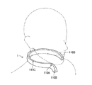
- FIG. 1 is a diagram illustrating an example of an appearance configuration of a voice processing system according to an embodiment of the present disclosure.
- FIG. 2 is a diagram illustrating an example of the appearance configuration of the voice processing system according to the present embodiment.
- FIG. 3 is a diagram illustrating an example of the appearance configuration of the voice processing system according to the present embodiment.
- FIG. 4 is a diagram illustrating another example of the appearance configuration of the voice processing system according to the present embodiment.
- FIG. 5 is a diagram illustrating another example of the appearance configuration of the voice processing system according to the present embodiment.
- FIG. 6 is a diagram illustrating an example of an appearance configuration of a voice processing system according to a comparative example.
- FIG. 7 is a diagram illustrated to describe an arrangement scheme of a voice acquisition unit according to the present embodiment.
- FIG. 8 is a diagram illustrated to describe the arrangement scheme of the voice acquisition unit according to the present embodiment.
- FIG. 9 is a diagram illustrated to describe the arrangement scheme of the voice acquisition unit according to the present embodiment.
- FIG. 10 is a diagram illustrated to describe the arrangement scheme of the voice acquisition unit according to the present embodiment.
- FIG. 11 is a block diagram illustrating an example of an internal configuration of the voice processing system according to the present embodiment.
- FIG. 12 is a flowchart illustrating an example of a voice signal processing procedure executed in the voice processing system according to the present embodiment.
- components having substantially the same functional configuration may be distinguished by attaching different alphabets after the same reference numerals.
- a plurality of components having substantially the same functional configuration are distinguished as necessary.
- only the same reference numeral is attached.
- voice acquisition units 110 A, 110 B, and 110 C they are simply referred to as a voice acquisition unit 110 .
- FIGS. 1 to 6 An appearance configuration of a voice processing system according to an embodiment of the present disclosure will be described with reference to FIGS. 1 to 6 .
- FIGS. 1 to 3 are diagrams illustrating an example of an appearance configuration of a voice processing system according to the present embodiment.
- the voice processing system 1 according to the present embodiment has a mounting unit that is shaped to make a half turn around the neck from both sides of the neck to the rear side (back side). Then, the mounting unit is attached to the user by being hooked on the user's neck.
- FIGS. 1 to 3 illustrate views of the state in which the mounting unit is attached to the user from various viewpoints.
- FIG. 1 is a perspective view thereof
- FIG. 2 is a perspective view thereof viewed from the right side of the user
- FIG. 3 is a plan view thereof viewed from the upper side of the user.
- directions such as left, right, upper, lower, fore, and back sides
- these directions are intended to indicate directions viewed from the center of the user's body (e.g., position of solar plexus) in the upright posture of the user as illustrated in FIG. 8 to be described later.
- the term “right side” indicates the direction of the right half of the user
- the term “left side” indicates the direction of the left half of the user
- the term “upper side” indicates the direction of the head side of the user
- the “lower side” indicates the direction of the feet side of the user.
- the term “fore side” indicates the direction in which the user's body faces
- the term “back side” indicates the direction of the rear side of the user.
- the mounting unit may be a neck hanging type that is worn around the user's neck.
- the mounting unit may be worn in close contact with the user's neck or may be worn with a space between them.
- An example of another shape of the neck hanging type mounting unit includes a pendant type that is attached to a user with a neck strap and a headset type having a neckband passing along the back side of the neck instead of a headband to be worn on the head.
- the usage pattern for the mounting type unit may have a pattern used while being directly worn on the human body.
- the usage pattern of using while being directly worn refers to a pattern used in a state where no object exists between the mounting type unit and the human body. In one example, this usage pattern corresponds to a case where the mounting unit illustrated in FIGS. 1 to 3 is worn to be in contact with the skin of the user's neck.
- various usage patterns such as a headset type and eyeglass type worn directly on the head, can be considered.
- the usage pattern of the mounting type unit may be a pattern that is used by being indirectly worn on the human body.
- the usage pattern of using while being indirectly worn refers to a pattern used in a state in which an object exists between the mounting type unit and the human body.
- this usage pattern corresponds to the case where the mounting unit illustrated in FIGS. 1 to 3 is worn to be in contact with the user from above the clothes, such as being worn to be hidden under the collar of the shirt.
- various patterns such as a pendant type to be attached to a user with a neck strap and a broach type to be fastened to clothes with fasteners, can be considered.
- the mounting unit has a plurality of voice acquisition units 110 ( 110 A, 110 B, 110 C, and 110 D) as illustrated in FIGS. 1 to 3 .
- the voice acquisition unit 110 acquires voice data, such as a voice of the user, a voice uttered by a user's conversation partner, and ambient environmental sound.
- the voice data acquired by the voice acquisition unit 110 is a target to be subject to beamforming processing for making user's voice clear, for making a voice uttered by a user's conversation partner clear, and for reducing other noise. As illustrated in FIGS.
- FIGS. 1 to 3 illustrate the configuration in which four voice acquisition units 110 are provided in the mounting unit, but the present technology is not limited to this example.
- the mounting unit may have at least three voice acquisition units, and may have five or more voice acquisition units.
- the voice processing system 1 may be implemented as a single mounting unit or may be implemented as a combination of a plurality of devices.
- the voice processing system 1 may be implemented as a combination of a neck hanging type mounting unit illustrated in FIGS. 1 to 3 and a wristband type mounting unit that is worn on the user's arm. Then, the voice processing system 1 may perform beamforming processing using voice data acquired by a plurality of voice acquisition units provided in a plurality of devices.
- the voice processing system 1 is assumed to be implemented as a single mounting unit illustrated in FIGS. 1 to 3 .
- FIGS. 4 and 5 are diagrams illustrating another example of the appearance configuration of the voice processing system according to the present embodiment.
- FIG. 4 illustrates the appearance configuration of a voice processing system 1 that includes a single glasses type mounting unit.
- FIG. 5 illustrates the appearance configuration of a voice processing system 1 that includes a single neckband type mounting unit.
- the voice processing system 1 has a plurality of voice acquisition units 110 ( 110 A, 110 B, 110 C, and 110 D) similarly to the examples illustrated in FIGS. 1 to 3 .
- FIG. 6 is a diagram illustrating an example of an appearance configuration of a voice processing system according to the comparative example.
- the left and right views of FIG. 6 illustrate an appearance configuration example of a so-called Bluetooth (registered trademark) headset.
- the voice processing system according to the comparative example has two voice acquisition units 910 ( 910 A and 910 B), and is attached to the user by putting it on the user's right ear.
- the voice processing system according to the comparative example has two voice acquisition units 910 ( 910 C and 910 D) provided symmetrically on cables connected to the left and right earphones. In this way, both the examples illustrated in the left and right views of FIG. 6 have two voice acquisition units.
- the microphone and the user's mouth are apart from each other in use, and the user's voice is buried in the noise. It is difficult to solve such a problem even if the beamforming processing using the voice data acquired by the two voice acquisition units as in the comparative example is performed.
- an arrangement of the voice acquisition unit 110 is developed to improve noise reduction performance in the case where noise is reduced by the beamforming processing.
- the arrangement scheme of the voice acquisition unit 110 will be described with reference to FIGS. 7 to 10 .
- FIG. 7 is a diagram illustrated to describe an arrangement scheme of the voice acquisition unit 110 according to the present embodiment.
- the first arrangement scheme is to arrange the voice acquisition unit 110 linearly with respect to a direction 210 in which the target sound arrives.
- the second arrangement scheme is to arrange the voice acquisition unit 110 linearly with respect to a direction 220 in which the noise to be reduced arrives.
- the voice acquisition units 110 A and 110 B can be arranged linearly with respect to the direction 210 of the user's mouth, which is the direction in which the user's voice regarded as target sound arrives.
- phase difference time difference
- the phase difference until the voice coming from the opposite direction 220 reaches the voice acquisition units 110 B and 110 A is also large.
- the user voice coming from the direction 210 of the user's mouth is enhanced by the beamforming processing to be performed by the controller 160 to be described later, and noise components coming from the opposite directions 220 A, 220 B, and 220 C are reduced.
- the arrangement scheme of the voice acquisition unit 110 associated with the direction in which the noise to be reduced arrives will be described in detail with reference to FIG. 8 .
- FIG. 8 is a diagram illustrated to describe the arrangement scheme of the voice acquisition unit 110 according to the present embodiment.
- the third arrangement scheme is to arrange the voice acquisition units 110 A and 110 B linearly with respect to the lower side direction.
- the voice processing system 1 is used outdoors, most of the noise occurred from the outside arrives from the direction of the ground (lower side direction) or the horizontal direction using the user's mouth illustrated in FIG. 8 as the reference.
- the noise coming from the direction of the ground is also called road noise.
- the voice acquisition unit 110 is arranged linearly with respect to the lower side direction in which the road noise arrives, and thus the road noise can be reduced efficiently by the beamforming processing.
- the voice acquisition units 110 A and 110 B are not necessarily arranged strictly linearly in the lower side direction (perpendicular direction), or they may be arranged to be inclined.
- FIG. 9 is a diagram illustrated to describe the arrangement scheme of the voice acquisition unit 110 according to the present embodiment.
- the fourth arrangement scheme is to arrange a plurality of voice acquisition units 110 three-dimensionally. Specifically, the shape formed by interconnecting positions where four voice acquisition units 110 are provided is three-dimensional.
- the term “three-dimensional” can be regarded as the case where three voice acquisition units 110 are provided and the remaining one voice acquisition unit 110 is not provided on a plane including the positions of the three voice acquisition units 110 . In such a three-dimensional arrangement, a phase difference occurs in the voice data acquired by any two or more voice acquisition units 110 for any voice coming from any direction, and thus it is possible to reduce the noise coming from any direction.
- the shape formed by interconnecting the positions where the four voice acquisition units 110 are provided is a regular tetrahedron.
- the shape formed by interconnecting the positions where the plurality of voice acquisition units 110 are provided is desirable to be a regular polyhedron such as a regular tetrahedron in which the distances from each of the voice acquisition units 110 to the user's mouth are equally spaced.
- the shape formed by interconnecting the positions where the four voice acquisition units 110 are provided undoubtedly may be a tetrahedron, but not necessarily a regular tetrahedron, depending on the shape of the mounting unit.
- FIG. 10 is a diagram illustrated to describe the arrangement scheme of the voice acquisition unit 110 according to the present embodiment.
- the fifth arrangement scheme is to bring at least one of the voice acquisition units 110 close to the user's mouth.
- at least one voice acquisition unit 110 can acquire the user voice having a larger sound volume than other noises. This makes it possible to increase further the effect of the user voice enhancement by the beamforming processing.
- a fifth voice acquisition unit 110 E may be provided at a position closer to the user's mouth than the four voice acquisition units 110 forming a tetrahedron.
- one (the voice acquisition unit 110 A in the example illustrated in the right view of FIG. 9 ) of the voice acquisition units 110 located at the vertexes of the tetrahedron may be provided closest to the user's mouth.
- the voice acquisition unit 110 may not necessarily completely conform to the arrangement scheme described above due to the constraint conditions such as the shape of the mounting unit and the weight of each component.
- the voice acquisition unit 110 A and the voice acquisition unit 110 B are arranged in the same direction when viewed from the user's mouth. Furthermore, in the state where the mounting unit is attached to the user, the distance between the voice acquisition unit 110 A (a first voice acquisition unit) included in the four voice acquisition units 110 and the user's mouth and the distance between the voice acquisition unit 110 B (a second voice acquisition unit) included in the four voice acquisition units 110 and the user's mouth are set to be different from each other. In this way, in the examples illustrated in FIGS. 1 to 3 , the voice acquisition units 110 A and 110 B are arranged linearly with respect to the direction of the user' mouth at which the target sound arrives, and thus it is possible to enhance efficiently the user voice by the beamforming processing.
- the voice acquisition unit 110 A and the voice acquisition unit 110 B are arranged in the same direction when viewed from the user's mouth. Furthermore, in a state where the mounting unit is attached to the user, the voice acquisition unit 110 A (the first voice acquisition unit) and the voice acquisition unit 110 B (the second voice acquisition unit) are provided to be closer to the user's feet than the user's mouth in the user's upright posture. In this way, in the examples illustrated in FIGS. 1 to 3 , the voice acquisition units 110 A and 110 B are arranged linearly with respect to the direction of the ground where the noise to be reduced arrives, and thus it is possible to reduce efficiently the noise by the beamforming processing.
- the shape formed by interconnecting the positions at which the voice acquisition units 110 A, 110 B, 110 C, and 110 D are provided is three-dimensional.
- the plurality of voice acquisition units 110 are arranged three-dimensionally, and thus it is possible to reduce the noise coming from any direction by the beamforming processing.
- the voice acquisition unit 110 A (the first voice acquisition unit) is provided at a position closest to the user's mouth.
- the voice acquisition unit 110 A is provided at a position close to the user's mouth, and thus it is possible to acquire the user voice having a larger sound volume than other noises.
- the voice acquisition unit 110 B (the second voice acquisition unit) is provided closer to the feet side of the user than the voice acquisition unit 110 A (the first voice acquisition unit) that is provided closest to the user's mouth in the user's upright posture.
- the voice acquisition unit 110 A is provided closer to the lower side than the user's mouth, but the voice acquisition unit 110 A may be provided closer to the upper side than the user's mouth.
- FIG. 11 is a block diagram illustrating an example of the internal configuration of the voice processing system 1 according to the present embodiment.
- the voice processing system 1 is configured to include voice acquisition units 110 A to 110 D, an image capture unit 120 , an operation unit 130 , a sensor unit 140 , a communication unit 150 , and a controller 160 .
- the voice acquisition unit 110 has a function of acquiring voice data for beamforming.
- the voice acquisition unit 110 acquires the user voice uttered by a user who wears the voice processing system 1 (the mounting unit) or acquires surrounding sound.
- the voice acquisition unit 110 is implemented as a microphone.
- the voice acquisition unit 110 may be provided in one mounting unit, may be provided in a device separate from the mounting unit, or may be distributed in a plurality of devices.
- the voice acquisition unit 110 may be provided in wristband type mounting units, eyeglass type mounting units, and smartphones, in addition to the neck hanging type mounting unit illustrated in FIGS. 1 to 3 .
- the voice acquisition unit 110 is not necessarily a directional microphone.
- the voice acquisition unit 110 may be a microphone having omnidirectional sensitivity.
- the term “omnidirectional sensitivity” means that there is no region (orientation) of insensitivity in the polar pattern. Such a microphone may also be referred to as a semi-directional microphone.
- the voice acquisition unit 110 may be a microphone whose sensitivity is uniform or substantially uniform in all directions.
- the term “uniform or substantially uniform in all directions” means that the sensitivity has a circular polar pattern, but it is not necessarily a true circle. In other words, the voice acquisition unit 110 may be an omnidirectional microphone.
- the voice acquisition unit 110 may include a microphone amplifier circuit or an analog-to-digital (A/D) converter that amplifies the voice signal acquired by the microphone.
- the voice acquisition unit 110 outputs the acquired voice data to the controller 160 .
- the image capture unit 120 is configured to include a lens system, a driving system, and a solid-state image sensor array.
- the lens system includes an image capture lens, a diaphragm, a zoom lens, a focus lens, and the like.
- the driving system causes a lens system to perform a focusing operation or a zooming operation.
- the solid-state image sensor array converts light for image capturing obtained by the lens system into electric energy to generate an image capture signal.
- the solid-state image sensor array may be implemented as, in one example, a charge coupled device (CCD) sensor array or a complementary metal-oxide-semiconductor (CMOS) sensor array.
- CCD charge coupled device
- CMOS complementary metal-oxide-semiconductor
- the image capture unit 120 may be provided to be capable of capturing the fore side of the user in a state in which the voice processing system (the mounting unit) 1 is attached to the user. In this case, the image capture unit 120 can capture an image of the user's conversation partner, in one example. Furthermore, the image capture unit 120 may be provided to be capable of capturing an image of the user's face in the state where the voice processing system 1 is attached to the user. In this case, the voice processing system 1 can specify the position of the user's mouth from the captured image. The image capture unit 120 outputs data of the captured image composed of digital signals to the controller 160 .
- the operation unit 130 is operated by the user and has a function of receiving an input from the user.
- the operation unit 130 may be implemented as a camera button that receives an input for instructing the image capture unit 120 to capture a still image, an input for instructing to start or stop capturing a moving image.
- the operation unit 130 may be implemented as a voice input button that receives an input for instructing the voice acquisition unit 110 to start or stop inputting the voice.
- the operation unit 130 may be implemented as a touch slider that receives a touch operation or a slide operation.
- the operation unit 130 may be implemented as a power button that accepts an operation for instructing the voice processing system 1 to turn the power ON or OFF.
- the operation unit 130 outputs information that indicates user input to the controller 160 .
- the sensor unit 140 has a function of sensing the state or the surrounding state of the user wearing the voice processing system 1 .
- the sensor unit 140 may include at least one of an accelerometer, a speedometer, a gyro sensor, a geomagnetic sensor, a global positioning system (GPS) module, and a vibration sensor.
- the sensor unit 140 may be provided in a device separate from the mounting unit, or may be provided in a distributed manner in a plurality of devices.
- the wristband type device may be provided with a pulse rate meter, and the smartphone may be provided with a vibration sensor.
- the sensor unit 140 outputs information indicating a result obtained by sensing to the controller 160 .
- the communication unit 150 is a communication module for exchanging data between the voice processing system 1 and other devices by wired or wireless connection.
- the communication unit 150 directly communicates, or wirelessly communicate via a network access point, with an external device, using a communication scheme such as wired local area network (LAN), wireless LAN, wireless fidelity (Wi-Fi, registered trademark), infrared communication, Bluetooth, and near field communication (NFC).
- LAN local area network
- Wi-Fi wireless fidelity
- NFC near field communication
- the communication unit 150 may transmit data acquired by the voice acquisition unit 110 , the image capture unit 120 , the operation unit 130 , and the sensor unit 140 .
- the other device performs beamforming processing, voice recognition processing, and the like.
- the communication unit 150 may receive the data acquired by them and output it to the controller 160 .
- the communication unit 150 may transmit the voice data obtained after the beamforming processing by the controller 160 to a storage device for storing the voice data.
- the controller 160 functions as both an arithmetic processing unit and a controller, and controls the overall operation in the voice processing system 1 in accordance with various programs.
- the controller 160 is implemented as an electronic circuit such as a central processing unit (CPU) and a microprocessor.
- the controller 160 may include read-only memory (ROM) for storing programs to be used, calculation parameters, or the like, and may include random-access memory (RAM) for temporarily storing appropriately varying parameters, or the like.
- the controller 160 performs beamforming processing of forming the directivity to acquire a voice coming from the direction of the user's mouth using a plurality of voice data items acquired by the voice acquisition unit 110 .
- the beamforming processing is a process of changing the degree of enhancement for each area where sound arrives. More specifically, the beamforming processing performed by the controller 160 may include a process of reducing sound coming from a specific area, or may include a process of enhancing sound coming from a desired orientation. In one example, the controller 160 may regard a voice coming from a direction other than the direction of the user's mouth as noise to be reduced. Furthermore, the controller 160 may enhance a voice coming from the direction of the user's mouth. As described above, the voice acquisition unit 110 does not necessarily have its own directivity. The controller 160 controls the directivity by performing the beamforming processing on the voice data acquired by each of the voice acquisition units 110 . The controller 160 can perform the beamforming processing using the phase difference between the voice data items acquired by each of the voice acquisition units 110 .
- the controller 160 can control the beamforming processing from various viewpoints.
- the controller 160 may control the direction and/or the range of forming the directivity from the viewpoint described below as an example.
- the controller 160 may control the beamforming processing based on the positional relationship between a noise source and the voice acquisition unit 110 .
- the noise source of a road is the ground, and thus the controller 160 may control the beamforming processing to reduce a voice coming from the direction of the ground.
- the controller 160 may control the beamforming processing to reduce the sound from the direction.
- the controller 160 may control the beamforming processing to reduce the sound coming from the position indicated by the user instruction.
- the controller 160 may control the beamforming processing based on the position of a speaker other than the user. In one example, the controller 160 may perform beamforming processing for enhancing a voice coming from a speaker other than the user. Furthermore, the controller 160 may perform beamforming processing for reducing a voice coming from another speaker other than the user. It is considered that there are various ways to specify the existence or position (direction) of other speakers than the user. In one example, in a case where a voice is acquired from a direction other than the user, the controller 160 may determine that there is another speaker and specify the direction. Furthermore, in a case where it is recognized that the voice of another speaker is acquired by voice recognition, the controller 160 may determine that another speaker is present.
- the controller 160 may specify the existence and the position of another speaker based on a result of image recognition on the captured image obtained by the image capture unit 120 . Furthermore, the controller 160 may compare the information on the position of the user acquired by the GPS module included in the sensor unit 140 with the information on the position of the other speaker, thereby specifying the existence and the position of the other speaker. Furthermore, the controller 160 may specify the existence and the position of the other speaker by measuring the radio wave intensity of radio waves (e.g., the radio field strength of Wi-Fi) emitted from a device held by the other speaker.
- the radio wave intensity of radio waves e.g., the radio field strength of Wi-Fi
- the controller 160 may control the beamforming processing based on information indicating the state of the user.
- the state of the user may refer to a motion state, such as when the user is running, walking, or riding a vehicle.
- the controller 160 can estimate the motion state of the user in accordance with the sensing result acquired by the sensor unit 140 .
- the controller 160 may estimate the detailed motion state by combining a plurality of sensing results.
- the combination of the sensing results obtained by the vibration sensor and the speedometer allows the controller 160 to estimate that the state is in bicycling if it is determined that the vibration level and velocity are larger than when walking.
- the controller 160 may estimate that the state is in riding in an automobile if the vibration level is lower than the case of riding a bicycle and the velocity is higher than the case of riding a bicycle. Then, the controller 160 may enlarge or reduce the range of directivity to be formed depending on the estimated motion state of the user. In one example, if the intensity of motion indicated by the motion state (e.g., numerical values outputted from each sensor) is relatively large, the controller 160 may increase the range of directivity, as compared with the case where the motion is small. Moreover, the enlargement or reduction of the range of directivity may be regarded as enlarging or reducing the range of an area indicating the sensitivity equal to or higher than a predetermined value with respect to the incoming sound.
- the state of the user may indicate the user's body posture such as the orientation and posture of the face of the user.
- the controller 160 may estimate the orientation of the user's face based on a result of image recognition on the captured image obtained by the image capture unit 120 , and may control the orientation of directivity depending on the orientation. In this case, even when the orientation of the face changes and the positional relationship between the user's mouth and the voice acquisition unit 110 changes, the controller 160 can control the directivity to acquire clearly a voice uttered from the mouth.
- the controller 160 may perform processing in accordance with the result of voice recognition executed based on the voice data obtained by performing the beamforming processing.
- the voice recognition processing may be executed by the controller 160 or may be executed by another device such as a server on the cloud.
- the controller 160 may control the operation of the voice processing system 1 based on a result of voice recognition.
- the controller 160 may control the directivity associated with the beamforming processing based on the result of voice recognition. This makes it possible for the user to instruct by voice, in one example, to direct the directivity in the direction of the voice to be recorded.
- the controller 160 may start or stop the image capturing with the camera, or record a specific sensing result, based on the result of voice recognition. This makes it possible for the user to instruct by voice, in one example, the landscape or motion state to be recorded.
- controller 160 can be implemented as, in one example, a mobile processor. As described above, the controller 160 may be included in the mounting unit, or may be included in any other device such as a smartphone or a server on the cloud.
- the voice processing system 1 can have various components.
- the voice processing system 1 may have a battery.
- the mounting unit can have a curved shape, and thus it is desirable that the battery may be a curved battery having a curved surface.
- the voice processing system 1 may have a connector for charging to which a cable for charging the battery can be connected.
- the connector for charging may be a connector for both charging and communication, which has a function as a connector for communication capable of connecting a cable for communication.
- the voice processing system 1 may have a vibrator that functions as an output device for the user.
- the voice processing system 1 may have a loudspeaker that functions as an output device to the user.
- the voice processing system 1 may have an earphone connector capable of connecting an earphone that functions as an output device to the user.
- the earphone connector may have a magnetic force, and the earphone connector and the earphone may be detachable by a magnetic force.
- the voice processing system 1 may have a storage unit for storing the voice data after the beamforming processing by the controller 160 .
- the internal configuration of the voice processing system 1 according to the present embodiment has been described above. Next, an operation process of the voice processing system 1 according to the present embodiment will be described with reference to FIG. 12 .
- FIG. 12 is a flowchart illustrating an example of a voice signal processing procedure executed in the voice processing system 1 according to the present embodiment.
- step S 102 the voice processing system 1 acquires voice data.
- the voice acquisition units 110 A, 110 B, 110 C, and 110 D acquire voice data and output it to the controller 160 .
- the voice processing system 1 acquires information indicating the positional relationship between a sound source and the voice acquisition unit 110 .
- the sound source may be a noise source, a user's mouth that is a source of user's voice, or a speaker other than the user.
- the controller 160 acquires information indicating the positional relationship between the sound source and the voice acquisition unit 110 , specifically, information indicating the direction viewed from the voice acquisition unit 110 .
- Examples of such information include a result of voice recognition on a voice acquired by the speech acquisition unit 110 , a result of image recognition on a captured image obtained by the image capture unit 120 , information indicating a user input acquired by the operation unit 130 , a sensing result by the sensor unit 140 , and information acquired from another device through the communication unit 150 .
- the voice processing system 1 acquires information indicating the state of the user.
- the controller 160 acquires information indicating the user's motion state or the user's body posture. Examples of such information include a result of voice recognition on a voice acquired by the speech acquisition unit 110 , a result of image recognition on a captured image obtained by the image capture unit 120 , information indicating a user input acquired by the operation unit 130 , a sensing result by the sensor unit 140 , and information acquired from another device through the communication unit 150 .
- the voice processing system 1 performs beamforming processing.
- the controller 160 performs the beamforming processing of forming directivity for acquiring a voice coming from the direction of the user's mouth, using the plurality of voice data items acquired in step S 102 .
- the controller 160 may control the beamforming processing to reduce the noise based on the positional relationship between the noise source and the voice acquisition unit 110 .
- the controller 160 may perform beamforming processing for enhancing or reducing a voice coming from a speaker other than the user based on the position of a speaker other than the user.
- the controller 160 may control the direction and/or range of forming the directivity depending on the state of the user.
- step S 110 the voice processing system 1 performs voice recognition processing.
- the controller 160 executes the voice recognition processing based on the voice data obtained by performing the beamforming processing. Then, the controller 160 may control the operation of the voice processing system 1 depending on a result obtained by performing the voice recognition.
- the voice processing system 1 has at least three voice acquisition units in the mounting unit. This makes it possible for the voice processing system 1 to acquire voice data suitable for performing beamforming processing for making the user's voice more clear.
- each device described in the present specification may be implemented by using software, hardware, or a combination of software and hardware.
- Programs that constitute the software may be stored previously, in one example, on storage medium (non-transitory media) provided inside or outside each device.
- storage medium non-transitory media
- such program is loaded onto random access memory (RAM) in executing it by a computer and executed by a processor such as CPU.
- RAM random access memory
- present technology may also be configured as below.
- a voice processing system including:
- a mounting unit configured to be attached to a user
- the mounting unit includes at least three voice acquisition units configured to acquire voice data for beamforming.
- the mounting unit includes at least four voice acquisition units, and
- the four voice acquisition units form a three-dimensional shape by interconnecting positions at which the four voice acquisition units are provided.
- the four voice acquisition units are provided so that a distance between a first voice acquisition unit included in the four voice acquisition units and a mouth of the user is different from a distance between a second voice acquisition unit included in the four voice acquisition units and the mouth of the user.
- the first voice acquisition unit is provided at a position closest to the mouth of the user as compared with the other voice acquisition units
- the second voice acquisition unit is provided closer to a feet side of the user than the first voice acquisition unit in an upright posture of the user.
- first voice acquisition unit and the second voice acquisition unit are provided closer to a feet side of the user than the mouth of the user in an upright posture of the user.
- the voice acquisition unit is a microphone having omnidirectional sensitivity.
- the voice acquisition unit is a microphone whose sensitivity is uniform or substantially uniform in all directions.
- the voice processing system according to any one of (2) to (7), further including:
- a controller configured to perform beamforming processing of forming directivity for acquiring a voice coming from a direction of the mouth of the user using a plurality of voice data items acquired by the voice acquisition unit.
- the beamforming processing is a process of changing a degree of enhancement for each area where sound arrives.
- the beamforming processing includes a process of reducing sound coming from a specific area.
- controller controls the beamforming processing based on positional relationship between a noise source and the voice acquisition unit.
- controller controls the beamforming processing based on a position of a speaker other than the user.
- controller controls the beamforming processing based on information indicating a state of the user.
- controller performs processing in accordance with a result of voice recognition executed based on voice data subjected to the beamforming processing.
- controller controls an operation of the voice processing system based on the result of the voice recognition.
- controller controls the directivity based on the result of the voice recognition.
- the mounting unit includes the controller.
- the mounting unit is worn around a neck of the user.
Landscapes
- Engineering & Computer Science (AREA)
- Health & Medical Sciences (AREA)
- Acoustics & Sound (AREA)
- Physics & Mathematics (AREA)
- Signal Processing (AREA)
- Otolaryngology (AREA)
- Human Computer Interaction (AREA)
- Audiology, Speech & Language Pathology (AREA)
- Multimedia (AREA)
- Computational Linguistics (AREA)
- Quality & Reliability (AREA)
- General Health & Medical Sciences (AREA)
- Circuit For Audible Band Transducer (AREA)
- Obtaining Desirable Characteristics In Audible-Bandwidth Transducers (AREA)
- User Interface Of Digital Computer (AREA)
Applications Claiming Priority (3)
| Application Number | Priority Date | Filing Date | Title |
|---|---|---|---|
| JP2014-213496 | 2014-10-20 | ||
| JP2014213496 | 2014-10-20 | ||
| PCT/JP2015/070040 WO2016063587A1 (ja) | 2014-10-20 | 2015-07-13 | 音声処理システム |
Related Parent Applications (1)
| Application Number | Title | Priority Date | Filing Date |
|---|---|---|---|
| PCT/JP2015/070040 A-371-Of-International WO2016063587A1 (ja) | 2014-10-20 | 2015-07-13 | 音声処理システム |
Related Child Applications (1)
| Application Number | Title | Priority Date | Filing Date |
|---|---|---|---|
| US16/012,473 Continuation US10674258B2 (en) | 2014-10-20 | 2018-06-19 | Voice processing system |
Publications (2)
| Publication Number | Publication Date |
|---|---|
| US20170280239A1 US20170280239A1 (en) | 2017-09-28 |
| US10306359B2 true US10306359B2 (en) | 2019-05-28 |
Family
ID=55760637
Family Applications (3)
| Application Number | Title | Priority Date | Filing Date |
|---|---|---|---|
| US15/504,063 Active US10306359B2 (en) | 2014-10-20 | 2015-07-13 | Voice processing system |
| US16/012,473 Active US10674258B2 (en) | 2014-10-20 | 2018-06-19 | Voice processing system |
| US16/816,479 Active US11172292B2 (en) | 2014-10-20 | 2020-03-12 | Voice processing system |
Family Applications After (2)
| Application Number | Title | Priority Date | Filing Date |
|---|---|---|---|
| US16/012,473 Active US10674258B2 (en) | 2014-10-20 | 2018-06-19 | Voice processing system |
| US16/816,479 Active US11172292B2 (en) | 2014-10-20 | 2020-03-12 | Voice processing system |
Country Status (5)
| Country | Link |
|---|---|
| US (3) | US10306359B2 (de) |
| EP (2) | EP3211918B1 (de) |
| JP (2) | JP6503559B2 (de) |
| CN (3) | CN108683972B (de) |
| WO (1) | WO2016063587A1 (de) |
Cited By (3)
| Publication number | Priority date | Publication date | Assignee | Title |
|---|---|---|---|---|
| US11172293B2 (en) * | 2018-07-11 | 2021-11-09 | Ambiq Micro, Inc. | Power efficient context-based audio processing |
| US20220248131A1 (en) * | 2021-02-04 | 2022-08-04 | Hitachi-Lg Data Storage, Inc. | Sound acquisition apparatus and sound acquisition method |
| US11468884B2 (en) * | 2017-05-08 | 2022-10-11 | Sony Corporation | Method, apparatus and computer program for detecting voice uttered from a particular position |
Families Citing this family (37)
| Publication number | Priority date | Publication date | Assignee | Title |
|---|---|---|---|---|
| WO2017027397A2 (en) * | 2015-08-07 | 2017-02-16 | Cirrus Logic International Semiconductor, Ltd. | Event detection for playback management in an audio device |
| WO2017060828A1 (en) | 2015-10-08 | 2017-04-13 | Cordio Medical Ltd. | Assessment of a pulmonary condition by speech analysis |
| JP2018007256A (ja) * | 2016-07-04 | 2018-01-11 | イーエム−テック・カンパニー・リミテッドEM−TECH.Co.,Ltd. | オーディオフォーカシング機能を備える音声増幅装置 |
| WO2018051663A1 (ja) * | 2016-09-13 | 2018-03-22 | ソニー株式会社 | 音源位置推定装置及びウェアラブルデバイス |
| WO2018116678A1 (ja) | 2016-12-22 | 2018-06-28 | ソニー株式会社 | 情報処理装置及びその制御方法 |
| JP1589838S (de) * | 2017-01-20 | 2017-11-06 | ||
| EP3633496B1 (de) | 2017-05-23 | 2022-07-20 | Sony Group Corporation | Informationsverarbeitungsvorrichtung |
| JP6766086B2 (ja) | 2017-09-28 | 2020-10-07 | キヤノン株式会社 | 撮像装置およびその制御方法 |
| CN111417919A (zh) | 2017-12-08 | 2020-07-14 | 索尼公司 | 信息处理装置及其控制方法和记录介质 |
| CN108235165B (zh) * | 2017-12-13 | 2020-09-15 | 安克创新科技股份有限公司 | 一种麦克风颈环耳机 |
| CN108235164B (zh) * | 2017-12-13 | 2020-09-15 | 安克创新科技股份有限公司 | 一种麦克风颈环耳机 |
| JP2019186630A (ja) * | 2018-04-03 | 2019-10-24 | キヤノン株式会社 | 撮像装置及びその制御方法及びプログラム |
| CN112513983B (zh) * | 2018-06-21 | 2024-12-17 | 奇跃公司 | 可穿戴系统语音处理 |
| US10847177B2 (en) * | 2018-10-11 | 2020-11-24 | Cordio Medical Ltd. | Estimating lung volume by speech analysis |
| US11587563B2 (en) | 2019-03-01 | 2023-02-21 | Magic Leap, Inc. | Determining input for speech processing engine |
| US12494224B2 (en) | 2019-03-12 | 2025-12-09 | Cordio Medical Ltd. | Analyzing speech using speech-sample alignment and segmentation based on acoustic features |
| US12512114B2 (en) | 2019-03-12 | 2025-12-30 | Cordio Medical Ltd. | Analyzing speech using speech models and segmentation based on acoustic features |
| US11011188B2 (en) | 2019-03-12 | 2021-05-18 | Cordio Medical Ltd. | Diagnostic techniques based on speech-sample alignment |
| US11024327B2 (en) | 2019-03-12 | 2021-06-01 | Cordio Medical Ltd. | Diagnostic techniques based on speech models |
| US12488805B2 (en) | 2019-03-12 | 2025-12-02 | Cordio Medical Ltd. | Using optimal articulatory event-types for computer analysis of speech |
| WO2020214844A1 (en) | 2019-04-19 | 2020-10-22 | Magic Leap, Inc. | Identifying input for speech recognition engine |
| CN119521079A (zh) * | 2019-05-22 | 2025-02-25 | 所乐思科技有限公司 | 戴在用户头部的设备、用于选择在戴在用户头部的装置上接收的声音信号的方法 |
| US11328740B2 (en) | 2019-08-07 | 2022-05-10 | Magic Leap, Inc. | Voice onset detection |
| JP6719140B1 (ja) | 2019-11-15 | 2020-07-08 | Fairy Devices株式会社 | 首掛け型装置 |
| WO2021100331A1 (ja) * | 2019-11-20 | 2021-05-27 | ダイキン工業株式会社 | 遠隔作業支援システム |
| JP7408414B2 (ja) * | 2020-01-27 | 2024-01-05 | シャープ株式会社 | ウェアラブルマイクスピーカ |
| US11484211B2 (en) | 2020-03-03 | 2022-11-01 | Cordio Medical Ltd. | Diagnosis of medical conditions using voice recordings and auscultation |
| US11917384B2 (en) | 2020-03-27 | 2024-02-27 | Magic Leap, Inc. | Method of waking a device using spoken voice commands |
| US11417342B2 (en) | 2020-06-29 | 2022-08-16 | Cordio Medical Ltd. | Synthesizing patient-specific speech models |
| JP6786139B1 (ja) * | 2020-07-06 | 2020-11-18 | Fairy Devices株式会社 | 音声入力装置 |
| US12417766B2 (en) | 2020-09-30 | 2025-09-16 | Magic Leap, Inc. | Voice user interface using non-linguistic input |
| US12334105B2 (en) | 2020-11-23 | 2025-06-17 | Cordio Medical Ltd. | Detecting impaired physiological function by speech analysis |
| JP7680883B2 (ja) * | 2021-05-26 | 2025-05-21 | シャープ株式会社 | 音声処理システム及び音声処理方法 |
| US12518774B2 (en) | 2023-02-05 | 2026-01-06 | Cordio Medical Ltd. | Identifying optimal articulatory event-types for computer analysis of speech |
| US12555595B2 (en) | 2023-05-18 | 2026-02-17 | Cordio Medical Ltd. | Converting a sequence of speech records of a human subject into a sequence of indicators of a physiological state of the subject |
| CN119895898A (zh) * | 2023-08-24 | 2025-04-25 | 京东方科技集团股份有限公司 | 音频装置及其工作方法、vr设备 |
| JP7653087B1 (ja) | 2023-09-29 | 2025-03-28 | Fairy Devices株式会社 | 双方向通信方法、プログラム、およびウェアラブル端末 |
Citations (17)
| Publication number | Priority date | Publication date | Assignee | Title |
|---|---|---|---|---|
| US20050060142A1 (en) | 2003-09-12 | 2005-03-17 | Erik Visser | Separation of target acoustic signals in a multi-transducer arrangement |
| US20070167671A1 (en) * | 2005-11-30 | 2007-07-19 | Miller Scott A Iii | Dual feedback control system for implantable hearing instrument |
| US20080187148A1 (en) * | 2007-02-05 | 2008-08-07 | Sony Corporation | Headphone device, sound reproduction system, and sound reproduction method |
| US20090129620A1 (en) | 2006-02-27 | 2009-05-21 | Junichi Tagawa | Wearable terminal, mobile imaging sound collecting device, and device, method, and program for implementing them |
| US20090136056A1 (en) | 2006-06-27 | 2009-05-28 | Bo Franzen | Device in a headset |
| US20100202626A1 (en) * | 2009-02-12 | 2010-08-12 | Sony Corporation | Control device, control method and control program |
| US20120051548A1 (en) | 2010-02-18 | 2012-03-01 | Qualcomm Incorporated | Microphone array subset selection for robust noise reduction |
| WO2012069973A1 (en) | 2010-11-24 | 2012-05-31 | Koninklijke Philips Electronics N.V. | A device comprising a plurality of audio sensors and a method of operating the same |
| US20120163625A1 (en) * | 2010-12-22 | 2012-06-28 | Sony Ericsson Mobile Communications Ab | Method of controlling audio recording and electronic device |
| US20130070935A1 (en) | 2011-09-19 | 2013-03-21 | Bitwave Pte Ltd | Multi-sensor signal optimization for speech communication |
| CN202998463U (zh) | 2012-12-11 | 2013-06-12 | 启通科技有限公司 | 一种挂颈式助听器 |
| US20130173266A1 (en) | 2011-12-28 | 2013-07-04 | Fuji Xerox Co., Ltd. | Voice analyzer and voice analysis system |
| EP2736272A1 (de) | 2012-11-22 | 2014-05-28 | ETH Zurich | Tragbare Mikrofonanordnungsvorrichtung |
| US20140219471A1 (en) * | 2013-02-06 | 2014-08-07 | Apple Inc. | User voice location estimation for adjusting portable device beamforming settings |
| US20140278394A1 (en) | 2013-03-12 | 2014-09-18 | Motorola Mobility Llc | Apparatus and Method for Beamforming to Obtain Voice and Noise Signals |
| US20140334630A1 (en) * | 2013-05-13 | 2014-11-13 | Sound In Motion Ltd. | Adding audio sound effects to movies |
| US20150049892A1 (en) * | 2013-08-19 | 2015-02-19 | Oticon A/S | External microphone array and hearing aid using it |
Family Cites Families (16)
| Publication number | Priority date | Publication date | Assignee | Title |
|---|---|---|---|---|
| JPH0631835Y2 (ja) | 1988-06-27 | 1994-08-22 | 株式会社オーディオテクニカ | 咽喉マイクロホンの保持装置 |
| US5793875A (en) * | 1996-04-22 | 1998-08-11 | Cardinal Sound Labs, Inc. | Directional hearing system |
| US6091832A (en) * | 1996-08-12 | 2000-07-18 | Interval Research Corporation | Wearable personal audio loop apparatus |
| JP2001095098A (ja) * | 1999-09-27 | 2001-04-06 | Harada Denshi Kogyo Kk | 体感補聴器 |
| JP2005303574A (ja) | 2004-04-09 | 2005-10-27 | Toshiba Corp | 音声認識ヘッドセット |
| CN101300897A (zh) * | 2005-11-01 | 2008-11-05 | 皇家飞利浦电子股份有限公司 | 包括声音跟踪装置的助听器 |
| JP2009017083A (ja) * | 2007-07-03 | 2009-01-22 | Data Bank Commerce:Kk | ノイズキャンセル装置 |
| JP2012133250A (ja) * | 2010-12-24 | 2012-07-12 | Sony Corp | 音情報表示装置、音情報表示方法およびプログラム |
| CN102393520B (zh) * | 2011-09-26 | 2013-07-31 | 哈尔滨工程大学 | 基于目标回波多普勒特性的声纳运动目标成像方法 |
| JP5772448B2 (ja) * | 2011-09-27 | 2015-09-02 | 富士ゼロックス株式会社 | 音声解析システムおよび音声解析装置 |
| CN103024629B (zh) * | 2011-09-30 | 2017-04-12 | 斯凯普公司 | 处理信号 |
| WO2013082455A1 (en) * | 2011-12-01 | 2013-06-06 | Maui Imaging, Inc. | Motion detection using ping-based and multiple aperture doppler ultrasound |
| JP2013191996A (ja) | 2012-03-13 | 2013-09-26 | Seiko Epson Corp | 音響装置 |
| RU2520184C1 (ru) * | 2012-12-28 | 2014-06-20 | Алексей Леонидович УШАКОВ | Гарнитура для мобильного электронного устройства |
| CN103135092A (zh) * | 2013-02-05 | 2013-06-05 | 中国科学院上海微系统与信息技术研究所 | 一种微孔径声阵列运动目标定向方法 |
| WO2014163797A1 (en) * | 2013-03-13 | 2014-10-09 | Kopin Corporation | Noise cancelling microphone apparatus |
-
2015
- 2015-07-13 JP JP2016555104A patent/JP6503559B2/ja active Active
- 2015-07-13 EP EP15852448.8A patent/EP3211918B1/de active Active
- 2015-07-13 WO PCT/JP2015/070040 patent/WO2016063587A1/ja not_active Ceased
- 2015-07-13 US US15/504,063 patent/US10306359B2/en active Active
- 2015-07-13 EP EP18186728.4A patent/EP3413583A1/de active Pending
- 2015-09-23 CN CN201810681854.9A patent/CN108683972B/zh active Active
- 2015-09-23 CN CN201520742860.2U patent/CN205508399U/zh not_active Expired - Fee Related
- 2015-09-23 CN CN201510612564.5A patent/CN105529033B/zh active Active
-
2018
- 2018-06-19 US US16/012,473 patent/US10674258B2/en active Active
-
2019
- 2019-03-04 JP JP2019038212A patent/JP6747538B2/ja active Active
-
2020
- 2020-03-12 US US16/816,479 patent/US11172292B2/en active Active
Patent Citations (19)
| Publication number | Priority date | Publication date | Assignee | Title |
|---|---|---|---|---|
| US20050060142A1 (en) | 2003-09-12 | 2005-03-17 | Erik Visser | Separation of target acoustic signals in a multi-transducer arrangement |
| US20070167671A1 (en) * | 2005-11-30 | 2007-07-19 | Miller Scott A Iii | Dual feedback control system for implantable hearing instrument |
| US20090129620A1 (en) | 2006-02-27 | 2009-05-21 | Junichi Tagawa | Wearable terminal, mobile imaging sound collecting device, and device, method, and program for implementing them |
| US20090136056A1 (en) | 2006-06-27 | 2009-05-28 | Bo Franzen | Device in a headset |
| US20080187148A1 (en) * | 2007-02-05 | 2008-08-07 | Sony Corporation | Headphone device, sound reproduction system, and sound reproduction method |
| US20100202626A1 (en) * | 2009-02-12 | 2010-08-12 | Sony Corporation | Control device, control method and control program |
| US20120051548A1 (en) | 2010-02-18 | 2012-03-01 | Qualcomm Incorporated | Microphone array subset selection for robust noise reduction |
| WO2012069973A9 (en) | 2010-11-24 | 2013-05-10 | Koninklijke Philips Electronics N.V. | A device comprising a plurality of audio sensors and a method of operating the same |
| WO2012069973A1 (en) | 2010-11-24 | 2012-05-31 | Koninklijke Philips Electronics N.V. | A device comprising a plurality of audio sensors and a method of operating the same |
| EP2643981B1 (de) | 2010-11-24 | 2014-09-17 | Koninklijke Philips N.V. | Vorrichtung mit mehreren audiosensoren und betriebsverfahren dafür |
| US20120163625A1 (en) * | 2010-12-22 | 2012-06-28 | Sony Ericsson Mobile Communications Ab | Method of controlling audio recording and electronic device |
| US20130070935A1 (en) | 2011-09-19 | 2013-03-21 | Bitwave Pte Ltd | Multi-sensor signal optimization for speech communication |
| US20130173266A1 (en) | 2011-12-28 | 2013-07-04 | Fuji Xerox Co., Ltd. | Voice analyzer and voice analysis system |
| EP2736272A1 (de) | 2012-11-22 | 2014-05-28 | ETH Zurich | Tragbare Mikrofonanordnungsvorrichtung |
| CN202998463U (zh) | 2012-12-11 | 2013-06-12 | 启通科技有限公司 | 一种挂颈式助听器 |
| US20140219471A1 (en) * | 2013-02-06 | 2014-08-07 | Apple Inc. | User voice location estimation for adjusting portable device beamforming settings |
| US20140278394A1 (en) | 2013-03-12 | 2014-09-18 | Motorola Mobility Llc | Apparatus and Method for Beamforming to Obtain Voice and Noise Signals |
| US20140334630A1 (en) * | 2013-05-13 | 2014-11-13 | Sound In Motion Ltd. | Adding audio sound effects to movies |
| US20150049892A1 (en) * | 2013-08-19 | 2015-02-19 | Oticon A/S | External microphone array and hearing aid using it |
Non-Patent Citations (2)
| Title |
|---|
| Apr. 9, 2018, European Search Report issued for related EP Application No. 15852448.8. |
| Oct. 1, 2018, European Search Report issued for related EP Application No. 18186728.4. |
Cited By (3)
| Publication number | Priority date | Publication date | Assignee | Title |
|---|---|---|---|---|
| US11468884B2 (en) * | 2017-05-08 | 2022-10-11 | Sony Corporation | Method, apparatus and computer program for detecting voice uttered from a particular position |
| US11172293B2 (en) * | 2018-07-11 | 2021-11-09 | Ambiq Micro, Inc. | Power efficient context-based audio processing |
| US20220248131A1 (en) * | 2021-02-04 | 2022-08-04 | Hitachi-Lg Data Storage, Inc. | Sound acquisition apparatus and sound acquisition method |
Also Published As
| Publication number | Publication date |
|---|---|
| EP3211918B1 (de) | 2021-08-25 |
| JPWO2016063587A1 (ja) | 2017-08-03 |
| US11172292B2 (en) | 2021-11-09 |
| US20170280239A1 (en) | 2017-09-28 |
| CN105529033B (zh) | 2020-11-10 |
| CN105529033A (zh) | 2016-04-27 |
| EP3413583A1 (de) | 2018-12-12 |
| CN108683972A (zh) | 2018-10-19 |
| US10674258B2 (en) | 2020-06-02 |
| US20200213730A1 (en) | 2020-07-02 |
| EP3211918A1 (de) | 2017-08-30 |
| CN205508399U (zh) | 2016-08-24 |
| EP3211918A4 (de) | 2018-05-09 |
| JP2019134441A (ja) | 2019-08-08 |
| US20180317005A1 (en) | 2018-11-01 |
| JP6503559B2 (ja) | 2019-04-24 |
| WO2016063587A1 (ja) | 2016-04-28 |
| JP6747538B2 (ja) | 2020-08-26 |
| CN108683972B (zh) | 2022-08-09 |
Similar Documents
| Publication | Publication Date | Title |
|---|---|---|
| US11172292B2 (en) | Voice processing system | |
| US10841682B2 (en) | Communication network of in-ear utility devices having sensors | |
| CN113393856B (zh) | 拾音方法、装置和电子设备 | |
| US9838771B1 (en) | In-ear utility device having a humidity sensor | |
| US20160249141A1 (en) | System and method for improving hearing | |
| US10045130B2 (en) | In-ear utility device having voice recognition | |
| US20180295462A1 (en) | Shoulder-mounted robotic speakers | |
| US20130259244A1 (en) | Hearing device with an inertial measurement unit | |
| US20170347179A1 (en) | In-Ear Utility Device Having Tap Detector | |
| KR20160069475A (ko) | 지향성의 사운드 변형 | |
| US20170347183A1 (en) | In-Ear Utility Device Having Dual Microphones | |
| JP2023514462A (ja) | 眼鏡フレーム内に一体化可能な補聴システム | |
| JP2017158083A (ja) | 情報処理装置、制御方法、およびプログラム | |
| WO2014079578A1 (en) | Wearable microphone array apparatus | |
| CN106302974B (zh) | 一种信息处理的方法及电子设备 | |
| CN115361636A (zh) | 声音信号调整方法、装置、终端设备及存储介质 | |
| US20220027174A1 (en) | True wireless headphones with improved user interface to an experiential eco-system and related devices, methods, and systems | |
| TWI725668B (zh) | 注意力集中輔助系統 | |
| CN114584913B (zh) | Foa信号和双耳信号的获得方法、声场采集装置及处理装置 | |
| KR20240049565A (ko) | 사용자 전기 신호에 기초한 오디오 조정 | |
| US20210314698A1 (en) | Earphone device | |
| CN117499834B (zh) | 一种相机模块、耳机及控制方法 | |
| WO2025256593A1 (zh) | 一种测距方法、系统及相关装置 |
Legal Events
| Date | Code | Title | Description |
|---|---|---|---|
| AS | Assignment |
Owner name: SONY CORPORATION, JAPAN Free format text: ASSIGNMENT OF ASSIGNORS INTEREST;ASSIGNORS:SEKIYA, TOSHIYUKI;MORI, HIDETO;HANYUDA, MAKOTO;AND OTHERS;SIGNING DATES FROM 20170105 TO 20170201;REEL/FRAME:041721/0043 |
|
| STPP | Information on status: patent application and granting procedure in general |
Free format text: NOTICE OF ALLOWANCE MAILED -- APPLICATION RECEIVED IN OFFICE OF PUBLICATIONS |
|
| STPP | Information on status: patent application and granting procedure in general |
Free format text: PUBLICATIONS -- ISSUE FEE PAYMENT VERIFIED |
|
| STCF | Information on status: patent grant |
Free format text: PATENTED CASE |
|
| MAFP | Maintenance fee payment |
Free format text: PAYMENT OF MAINTENANCE FEE, 4TH YEAR, LARGE ENTITY (ORIGINAL EVENT CODE: M1551); ENTITY STATUS OF PATENT OWNER: LARGE ENTITY Year of fee payment: 4 |