US10272436B2 - Assay cartridge valve system - Google Patents
Assay cartridge valve system Download PDFInfo
- Publication number
- US10272436B2 US10272436B2 US14/412,866 US201314412866A US10272436B2 US 10272436 B2 US10272436 B2 US 10272436B2 US 201314412866 A US201314412866 A US 201314412866A US 10272436 B2 US10272436 B2 US 10272436B2
- Authority
- US
- United States
- Prior art keywords
- assay cartridge
- rotor
- valve
- stator
- cartridge
- Prior art date
- Legal status (The legal status is an assumption and is not a legal conclusion. Google has not performed a legal analysis and makes no representation as to the accuracy of the status listed.)
- Active, expires
Links
- 238000007836 assay cartridge Methods 0.000 title claims abstract description 59
- 238000007789 sealing Methods 0.000 claims description 46
- 238000001514 detection method Methods 0.000 claims description 14
- 238000004891 communication Methods 0.000 claims description 13
- 229920001971 elastomer Polymers 0.000 claims description 6
- 239000000806 elastomer Substances 0.000 claims description 6
- 230000006835 compression Effects 0.000 claims description 5
- 238000007906 compression Methods 0.000 claims description 5
- 239000002699 waste material Substances 0.000 claims description 5
- 238000002347 injection Methods 0.000 claims description 2
- 239000007924 injection Substances 0.000 claims description 2
- 239000012530 fluid Substances 0.000 description 27
- 239000003153 chemical reaction reagent Substances 0.000 description 16
- 238000003556 assay Methods 0.000 description 15
- 238000000034 method Methods 0.000 description 11
- 238000011109 contamination Methods 0.000 description 9
- 230000033001 locomotion Effects 0.000 description 8
- 238000003860 storage Methods 0.000 description 8
- 239000007788 liquid Substances 0.000 description 6
- 238000005259 measurement Methods 0.000 description 6
- 239000000356 contaminant Substances 0.000 description 5
- 238000013461 design Methods 0.000 description 5
- -1 detectable labels Substances 0.000 description 5
- 230000003287 optical effect Effects 0.000 description 5
- 238000003752 polymerase chain reaction Methods 0.000 description 5
- 230000008569 process Effects 0.000 description 5
- 229920002725 thermoplastic elastomer Polymers 0.000 description 5
- 238000004519 manufacturing process Methods 0.000 description 4
- 239000000463 material Substances 0.000 description 4
- 238000003466 welding Methods 0.000 description 4
- 239000002033 PVDF binder Substances 0.000 description 3
- 230000027455 binding Effects 0.000 description 3
- 238000011143 downstream manufacturing Methods 0.000 description 3
- 230000000670 limiting effect Effects 0.000 description 3
- 150000007523 nucleic acids Chemical class 0.000 description 3
- 102000039446 nucleic acids Human genes 0.000 description 3
- 108020004707 nucleic acids Proteins 0.000 description 3
- 239000012071 phase Substances 0.000 description 3
- 229920000515 polycarbonate Polymers 0.000 description 3
- 239000004417 polycarbonate Substances 0.000 description 3
- 239000005020 polyethylene terephthalate Substances 0.000 description 3
- 229920000139 polyethylene terephthalate Polymers 0.000 description 3
- 229920002981 polyvinylidene fluoride Polymers 0.000 description 3
- 238000012360 testing method Methods 0.000 description 3
- LFQSCWFLJHTTHZ-UHFFFAOYSA-N Ethanol Chemical compound CCO LFQSCWFLJHTTHZ-UHFFFAOYSA-N 0.000 description 2
- 239000004743 Polypropylene Substances 0.000 description 2
- 239000004793 Polystyrene Substances 0.000 description 2
- 238000003491 array Methods 0.000 description 2
- 239000000872 buffer Substances 0.000 description 2
- 230000007423 decrease Effects 0.000 description 2
- 238000003018 immunoassay Methods 0.000 description 2
- 238000010348 incorporation Methods 0.000 description 2
- 238000001746 injection moulding Methods 0.000 description 2
- 238000002955 isolation Methods 0.000 description 2
- 238000002156 mixing Methods 0.000 description 2
- 238000012986 modification Methods 0.000 description 2
- 230000004048 modification Effects 0.000 description 2
- 229920001155 polypropylene Polymers 0.000 description 2
- 229920002223 polystyrene Polymers 0.000 description 2
- 238000012545 processing Methods 0.000 description 2
- 238000011160 research Methods 0.000 description 2
- 238000010839 reverse transcription Methods 0.000 description 2
- 239000007787 solid Substances 0.000 description 2
- 239000000243 solution Substances 0.000 description 2
- 238000011144 upstream manufacturing Methods 0.000 description 2
- QJZYHAIUNVAGQP-UHFFFAOYSA-N 3-nitrobicyclo[2.2.1]hept-5-ene-2,3-dicarboxylic acid Chemical compound C1C2C=CC1C(C(=O)O)C2(C(O)=O)[N+]([O-])=O QJZYHAIUNVAGQP-UHFFFAOYSA-N 0.000 description 1
- 229920004943 Delrin® Polymers 0.000 description 1
- 241000237858 Gastropoda Species 0.000 description 1
- 102000001554 Hemoglobins Human genes 0.000 description 1
- 108010054147 Hemoglobins Proteins 0.000 description 1
- 229920005479 Lucite® Polymers 0.000 description 1
- 238000012408 PCR amplification Methods 0.000 description 1
- 239000004696 Poly ether ether ketone Substances 0.000 description 1
- 239000004809 Teflon Substances 0.000 description 1
- 229920006362 Teflon® Polymers 0.000 description 1
- 238000002835 absorbance Methods 0.000 description 1
- 239000011354 acetal resin Substances 0.000 description 1
- NIXOWILDQLNWCW-UHFFFAOYSA-N acrylic acid group Chemical group C(C=C)(=O)O NIXOWILDQLNWCW-UHFFFAOYSA-N 0.000 description 1
- 229920000122 acrylonitrile butadiene styrene Polymers 0.000 description 1
- 239000004676 acrylonitrile butadiene styrene Substances 0.000 description 1
- 238000004458 analytical method Methods 0.000 description 1
- 238000000149 argon plasma sintering Methods 0.000 description 1
- 230000009286 beneficial effect Effects 0.000 description 1
- JUPQTSLXMOCDHR-UHFFFAOYSA-N benzene-1,4-diol;bis(4-fluorophenyl)methanone Chemical compound OC1=CC=C(O)C=C1.C1=CC(F)=CC=C1C(=O)C1=CC=C(F)C=C1 JUPQTSLXMOCDHR-UHFFFAOYSA-N 0.000 description 1
- 238000004166 bioassay Methods 0.000 description 1
- 238000010256 biochemical assay Methods 0.000 description 1
- 239000013060 biological fluid Substances 0.000 description 1
- 239000008280 blood Substances 0.000 description 1
- 210000004369 blood Anatomy 0.000 description 1
- 238000000071 blow moulding Methods 0.000 description 1
- 238000005266 casting Methods 0.000 description 1
- 239000000919 ceramic Substances 0.000 description 1
- 238000006243 chemical reaction Methods 0.000 description 1
- 238000012875 competitive assay Methods 0.000 description 1
- 230000001276 controlling effect Effects 0.000 description 1
- 230000008878 coupling Effects 0.000 description 1
- 238000010168 coupling process Methods 0.000 description 1
- 238000005859 coupling reaction Methods 0.000 description 1
- 230000001419 dependent effect Effects 0.000 description 1
- 238000010790 dilution Methods 0.000 description 1
- 239000012895 dilution Substances 0.000 description 1
- 238000005516 engineering process Methods 0.000 description 1
- 238000011067 equilibration Methods 0.000 description 1
- 238000002474 experimental method Methods 0.000 description 1
- 239000000835 fiber Substances 0.000 description 1
- 239000011521 glass Substances 0.000 description 1
- YQOKLYTXVFAUCW-UHFFFAOYSA-N guanidine;isothiocyanic acid Chemical compound N=C=S.NC(N)=N YQOKLYTXVFAUCW-UHFFFAOYSA-N 0.000 description 1
- 238000010438 heat treatment Methods 0.000 description 1
- 239000004021 humic acid Substances 0.000 description 1
- 238000011534 incubation Methods 0.000 description 1
- 230000002452 interceptive effect Effects 0.000 description 1
- 230000007774 longterm Effects 0.000 description 1
- 238000004020 luminiscence type Methods 0.000 description 1
- 239000012139 lysis buffer Substances 0.000 description 1
- 238000003754 machining Methods 0.000 description 1
- 230000014759 maintenance of location Effects 0.000 description 1
- 239000002184 metal Substances 0.000 description 1
- 229910052751 metal Inorganic materials 0.000 description 1
- 150000002739 metals Chemical class 0.000 description 1
- 230000000116 mitigating effect Effects 0.000 description 1
- 238000011512 multiplexed immunoassay Methods 0.000 description 1
- 238000001216 nucleic acid method Methods 0.000 description 1
- 238000001821 nucleic acid purification Methods 0.000 description 1
- 239000004033 plastic Substances 0.000 description 1
- 229920003023 plastic Polymers 0.000 description 1
- 229920000058 polyacrylate Polymers 0.000 description 1
- 229920002530 polyetherether ketone Polymers 0.000 description 1
- 239000004926 polymethyl methacrylate Substances 0.000 description 1
- 229920006324 polyoxymethylene Polymers 0.000 description 1
- 229920001343 polytetrafluoroethylene Polymers 0.000 description 1
- 239000004810 polytetrafluoroethylene Substances 0.000 description 1
- 238000003825 pressing Methods 0.000 description 1
- 238000000159 protein binding assay Methods 0.000 description 1
- 230000002829 reductive effect Effects 0.000 description 1
- 230000001105 regulatory effect Effects 0.000 description 1
- 239000002689 soil Substances 0.000 description 1
- 239000007790 solid phase Substances 0.000 description 1
- 239000000126 substance Substances 0.000 description 1
- 230000007704 transition Effects 0.000 description 1
- 239000011534 wash buffer Substances 0.000 description 1
- 238000005406 washing Methods 0.000 description 1
Images


Classifications
-
- B—PERFORMING OPERATIONS; TRANSPORTING
- B01—PHYSICAL OR CHEMICAL PROCESSES OR APPARATUS IN GENERAL
- B01L—CHEMICAL OR PHYSICAL LABORATORY APPARATUS FOR GENERAL USE
- B01L3/00—Containers or dishes for laboratory use, e.g. laboratory glassware; Droppers
- B01L3/56—Labware specially adapted for transferring fluids
- B01L3/567—Valves, taps or stop-cocks
-
- B—PERFORMING OPERATIONS; TRANSPORTING
- B01—PHYSICAL OR CHEMICAL PROCESSES OR APPARATUS IN GENERAL
- B01L—CHEMICAL OR PHYSICAL LABORATORY APPARATUS FOR GENERAL USE
- B01L3/00—Containers or dishes for laboratory use, e.g. laboratory glassware; Droppers
- B01L3/50—Containers for the purpose of retaining a material to be analysed, e.g. test tubes
- B01L3/502—Containers for the purpose of retaining a material to be analysed, e.g. test tubes with fluid transport, e.g. in multi-compartment structures
- B01L3/5027—Containers for the purpose of retaining a material to be analysed, e.g. test tubes with fluid transport, e.g. in multi-compartment structures by integrated microfluidic structures, i.e. dimensions of channels and chambers are such that surface tension forces are important, e.g. lab-on-a-chip
- B01L3/502738—Containers for the purpose of retaining a material to be analysed, e.g. test tubes with fluid transport, e.g. in multi-compartment structures by integrated microfluidic structures, i.e. dimensions of channels and chambers are such that surface tension forces are important, e.g. lab-on-a-chip characterised by integrated valves
-
- B—PERFORMING OPERATIONS; TRANSPORTING
- B01—PHYSICAL OR CHEMICAL PROCESSES OR APPARATUS IN GENERAL
- B01L—CHEMICAL OR PHYSICAL LABORATORY APPARATUS FOR GENERAL USE
- B01L3/00—Containers or dishes for laboratory use, e.g. laboratory glassware; Droppers
- B01L3/50—Containers for the purpose of retaining a material to be analysed, e.g. test tubes
- B01L3/508—Containers for the purpose of retaining a material to be analysed, e.g. test tubes rigid containers not provided for above
- B01L3/5085—Containers for the purpose of retaining a material to be analysed, e.g. test tubes rigid containers not provided for above for multiple samples, e.g. microtitration plates
-
- F—MECHANICAL ENGINEERING; LIGHTING; HEATING; WEAPONS; BLASTING
- F16—ENGINEERING ELEMENTS AND UNITS; GENERAL MEASURES FOR PRODUCING AND MAINTAINING EFFECTIVE FUNCTIONING OF MACHINES OR INSTALLATIONS; THERMAL INSULATION IN GENERAL
- F16K—VALVES; TAPS; COCKS; ACTUATING-FLOATS; DEVICES FOR VENTING OR AERATING
- F16K11/00—Multiple-way valves, e.g. mixing valves; Pipe fittings incorporating such valves
- F16K11/02—Multiple-way valves, e.g. mixing valves; Pipe fittings incorporating such valves with all movable sealing faces moving as one unit
- F16K11/06—Multiple-way valves, e.g. mixing valves; Pipe fittings incorporating such valves with all movable sealing faces moving as one unit comprising only sliding valves, i.e. sliding closure elements
- F16K11/072—Multiple-way valves, e.g. mixing valves; Pipe fittings incorporating such valves with all movable sealing faces moving as one unit comprising only sliding valves, i.e. sliding closure elements with pivoted closure members
- F16K11/074—Multiple-way valves, e.g. mixing valves; Pipe fittings incorporating such valves with all movable sealing faces moving as one unit comprising only sliding valves, i.e. sliding closure elements with pivoted closure members with flat sealing faces
- F16K11/0743—Multiple-way valves, e.g. mixing valves; Pipe fittings incorporating such valves with all movable sealing faces moving as one unit comprising only sliding valves, i.e. sliding closure elements with pivoted closure members with flat sealing faces with both the supply and the discharge passages being on one side of the closure plates
-
- B—PERFORMING OPERATIONS; TRANSPORTING
- B01—PHYSICAL OR CHEMICAL PROCESSES OR APPARATUS IN GENERAL
- B01L—CHEMICAL OR PHYSICAL LABORATORY APPARATUS FOR GENERAL USE
- B01L2300/00—Additional constructional details
- B01L2300/06—Auxiliary integrated devices, integrated components
- B01L2300/0681—Filter
-
- B—PERFORMING OPERATIONS; TRANSPORTING
- B01—PHYSICAL OR CHEMICAL PROCESSES OR APPARATUS IN GENERAL
- B01L—CHEMICAL OR PHYSICAL LABORATORY APPARATUS FOR GENERAL USE
- B01L2300/00—Additional constructional details
- B01L2300/08—Geometry, shape and general structure
- B01L2300/0809—Geometry, shape and general structure rectangular shaped
- B01L2300/0816—Cards, e.g. flat sample carriers usually with flow in two horizontal directions
-
- B—PERFORMING OPERATIONS; TRANSPORTING
- B01—PHYSICAL OR CHEMICAL PROCESSES OR APPARATUS IN GENERAL
- B01L—CHEMICAL OR PHYSICAL LABORATORY APPARATUS FOR GENERAL USE
- B01L2300/00—Additional constructional details
- B01L2300/08—Geometry, shape and general structure
- B01L2300/0861—Configuration of multiple channels and/or chambers in a single devices
- B01L2300/0867—Multiple inlets and one sample wells, e.g. mixing, dilution
-
- B—PERFORMING OPERATIONS; TRANSPORTING
- B01—PHYSICAL OR CHEMICAL PROCESSES OR APPARATUS IN GENERAL
- B01L—CHEMICAL OR PHYSICAL LABORATORY APPARATUS FOR GENERAL USE
- B01L2300/00—Additional constructional details
- B01L2300/08—Geometry, shape and general structure
- B01L2300/0861—Configuration of multiple channels and/or chambers in a single devices
- B01L2300/0874—Three dimensional network
-
- B—PERFORMING OPERATIONS; TRANSPORTING
- B01—PHYSICAL OR CHEMICAL PROCESSES OR APPARATUS IN GENERAL
- B01L—CHEMICAL OR PHYSICAL LABORATORY APPARATUS FOR GENERAL USE
- B01L2400/00—Moving or stopping fluids
- B01L2400/04—Moving fluids with specific forces or mechanical means
- B01L2400/0475—Moving fluids with specific forces or mechanical means specific mechanical means and fluid pressure
- B01L2400/0487—Moving fluids with specific forces or mechanical means specific mechanical means and fluid pressure fluid pressure, pneumatics
-
- B—PERFORMING OPERATIONS; TRANSPORTING
- B01—PHYSICAL OR CHEMICAL PROCESSES OR APPARATUS IN GENERAL
- B01L—CHEMICAL OR PHYSICAL LABORATORY APPARATUS FOR GENERAL USE
- B01L2400/00—Moving or stopping fluids
- B01L2400/06—Valves, specific forms thereof
- B01L2400/0622—Valves, specific forms thereof distribution valves, valves having multiple inlets and/or outlets, e.g. metering valves, multi-way valves
-
- B—PERFORMING OPERATIONS; TRANSPORTING
- B01—PHYSICAL OR CHEMICAL PROCESSES OR APPARATUS IN GENERAL
- B01L—CHEMICAL OR PHYSICAL LABORATORY APPARATUS FOR GENERAL USE
- B01L2400/00—Moving or stopping fluids
- B01L2400/06—Valves, specific forms thereof
- B01L2400/0633—Valves, specific forms thereof with moving parts
- B01L2400/0644—Valves, specific forms thereof with moving parts rotary valves
-
- Y—GENERAL TAGGING OF NEW TECHNOLOGICAL DEVELOPMENTS; GENERAL TAGGING OF CROSS-SECTIONAL TECHNOLOGIES SPANNING OVER SEVERAL SECTIONS OF THE IPC; TECHNICAL SUBJECTS COVERED BY FORMER USPC CROSS-REFERENCE ART COLLECTIONS [XRACs] AND DIGESTS
- Y10—TECHNICAL SUBJECTS COVERED BY FORMER USPC
- Y10T—TECHNICAL SUBJECTS COVERED BY FORMER US CLASSIFICATION
- Y10T436/00—Chemistry: analytical and immunological testing
- Y10T436/25—Chemistry: analytical and immunological testing including sample preparation
- Y10T436/2575—Volumetric liquid transfer
Definitions
- This application relates to apparatuses incorporating multi-port valves and methods of using such apparatuses for conducting chemical, biochemical and/or biological assays on a sample.
- the invention provides an assay cartridge comprising: (a) a plurality of chambers, and (b) a fluidic network including: (i) a plurality of fluidic conduits connecting the plurality of chambers; and (ii) a multi-port valve comprising:
- stator comprising a rotor engagement member, a valve inlet, and a plurality of valve outlets accessible to one or more fluidic conduits in the fluidic network;
- valve inlet when engaged, the rotor is rotated to fluidically connect the valve inlet to one of the valve outlets through a fluidic connector on the rotor while the sealing member seals the remaining valve outlets.
- the spring comprises a top surface, a bottom surface, a cylindrical body comprising a central vertical axis disposed between the top and bottom surfaces and a plurality of pairs of axially spaced radially extending grooves surrounding the central vertical axis, and a plurality of through-holes intersecting the central vertical axis at a position perpendicular to the intersection of the plurality of pairs of grooves to the central vertical axis.
- the plurality of pairs of grooves and the plurality of through-holes define a plurality of ribs in the cylindrical body.
- the spring is an integrated spring, e.g., a corrugated stem.
- the multi-port valve of the assay cartridge of the invention can selectively open one of the plurality of valve outlets by (a) rotating the rotor via engagement between an instrument stepper motor (a drive element) and the instrument interface element, and (b) disengaging the stator and rotor engagement members, thereby fluidically connecting the valve inlet to one of the plurality of valve outlets through the fluidic connector and sealing the remaining valve outlets via compression of the sealing member against the stator.
- the invention also includes a method of using a multi-port valve in an assay cartridge, wherein the cartridge comprises a plurality of chambers and a fluidic network including (i) a plurality of fluidic conduits connecting the plurality of chambers; and (ii) a multi-port valve comprising:
- stator comprising a rotor engagement member, a valve inlet, and a plurality of valve outlets accessible to one or more fluidic conduits in the fluidic network;
- a rotor biased toward the stator comprising a sealing member disposed between the rotor and the stator, a spring, an instrument interface element, and a stator engagement member configured to disengage the rotor when the stator engagement member is in communication with the rotor engagement member,
- a method of moving fluid in an assay cartridge comprising a plurality of chambers and a fluidic network including a plurality of fluidic conduits connecting the plurality of chambers and a multi-port valve having:
- stator comprising a rotor engagement member, a valve inlet, and a plurality of valve outlets accessible to one or more fluidic conduits in the fluidic network;
- a rotor biased toward the stator comprising a sealing member disposed between the rotor and the stator, a spring, an instrument interface element, and a stator engagement member configured to disengage the rotor when the stator engagement member is in communication with the rotor engagement member,
- FIG. 1 depicts a simplified pictorial representation of a cartridge-based assay module incorporating a multi-port valve of the invention.
- FIGS. 2( a )-( i ) show various embodiments of a multi-port valve.
- FIGS. 2( a )-( b ) illustrate a multi-port valve that interfaces with a plurality of channels or conduits in a cartridge fluidic network to direct the flow of fluid from one of a plurality of channels to a single valve inlet ( FIG. 2( a ) ) or from a single valve inlet to one of a plurality of outlets ( FIG. 2( b ) ).
- FIGS. 2( c )-( d ) show how fluid is directed in a multi-port valve from a valve inlet to one of a plurality of valve outlets and, upon rotation of the valve, to an adjacent outlet.
- FIGS. 2( g )-( i ) show various alternative embodiments for the connection of multi-port valves in series.
- FIGS. 3( a )-( c ) illustrate the components of a multi-port valve, i.e., a cap, a spring, rotor, and stator and FIGS. 3( b )-( c ) provide a detailed view of the fluidic channel between the rotor and the sealing member.
- FIG. 4 shows the results of an experiment conducted to determine the amount of carryover in a multi-port valve.
- the amount of carryover was determined by flowing a buffer with free, unbound label through the valve and then measuring the amount of label in successive wash slugs.
- the graph shows that an approximate five-fold dilution factor is achievable with each round of washing (after the first cycle), and a wash quality of 10,000 is achievable with 5-6 washes.
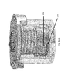
- FIGS. 5( a )-( j ) show the components of the valve and provide a detailed illustration of the design of the spring and the instrument interface element.
- FIG. 5( a ) provides a detailed view of the retention cap, rotor, and stator
- FIGS. 5( b )-( d ) show the instrument interface element and the spring from various vantage points.
- FIGS. 5( e )-( g ) show various embodiments of the instrument interface element
- FIGS. 5( h )-( j ) illustrate the corresponding instrument engagement element and how the stepper motor (drive element) engages with the instrument interface element.
- FIG. 6( a )-( g ) show the storage elements of the rotor and stator, i.e., the stator engagement member and the rotor engagement member, respectively.
- FIGS. 6( b )-( e ) illustrate how the rotor and stator engagement members communicate to engage/disengage the rotor from the stator and
- FIGS. 6( f )-( g ) illustrate an alternate embodiment of the storage elements and communication between the stator and rotor engagement members.
- the invention relates to a multi-port valve that can be used in an assay cartridge to facilitate fluid isolation in and selective fluidic communication throughout the cartridge fluidic network.
- An assay cartridge of the invention incorporates one or more fluidic components such as compartments, wells, chambers, fluidic conduits, fluid ports/vents, filters, valves, and the like and/or one or more detection components such as electrodes, electrode contacts, sensors (e.g., electrochemical sensors, fluid sensors, mass sensors, optical sensors, capacitive sensors, impedence sensors, optical waveguides, etc.), detection windows (e.g., windows configured to allow optical measurements on samples in the cartridge, such as absorbance, light scattering, refraction, or reflection, fluorescence, phosphorescence, chemiluminescence, electrochemiluminescence, etc.), and the like.
- fluidic components such as compartments, wells, chambers, fluidic conduits, fluid ports/vents, filters, valves, and the like
- detection components such as electrodes, electrode contacts, sensors (e
- a cartridge can also comprise reagents for carrying out an assay such as binding reagents, detectable labels, sample processing reagents, wash solutions, buffers, etc, and the reagents can be present in liquid form, solid form and/or immobilized on the surface of solid phase supports present in the cartridge.
- Certain preferred cartridge embodiments also comprise detection chambers having the electrode arrays and/or binding domains.
- FIG. 1 depicts a simplified schematic of a cartridge-based biochemical detection system ( 100 ) that incorporates a multi-port valve ( 101 ).
- the cartridge includes one or more fluidic components ( 102 , 105 and 107 ) that are linked to each other through a multi-port valve ( 101 ) and can also include fluidic conduits linking these components to additional components, as exemplified, by the connection of component ( 107 ) to additional fluidic components ( 103 ) and ( 104 ) (chambers ( 103 ) and ( 104 ) are connected via a T-junction in FIG.
- Fluidic components that can be linked in this manner include sample introduction chambers, solid and liquid reagent storage chambers, reaction chambers, mixing chambers, filters, valves, and detection chambers and other fluidic components known in the art of fluidic assay devices.
- the cartridge can also include vent ports ( 106 ) in fluidic communication with the fluidic components (directly or through vent conduits) so as to allow the equilibration of fluid in the component with the atmosphere or to allow for the directed movement of fluid into or out of a specified chamber by the application of positive or negative pressure.
- the multi-port valve allows for the selective movement of fluid between the chambers linked to the valve and, in the case of cartridge ( 100 ), the selective movement of fluid from component ( 107 ) to component ( 102 ) or one of components ( 105 ) and/or the selective movement of fluid to component ( 107 ) from component ( 102 ) or one of components ( 105 ).
- the cartridge has sample chambers ( 102 ), one or more detection chambers ( 103 ) (preferably, detection chambers adapted for use in electrochemiluminescence measurements) and one or more waste chambers ( 104 ).
- the sample chamber is connected by a fluid conduit (A) directed through a multi-port valve ( 101 ) so that a sample introduced into a sample chamber can be delivered through a conduit (F) in the fluidic network into one or more detection chambers for analysis and then passed into one or more waste chambers for disposal (as shown in the embodiment in FIG. 1 , a filter ( 107 ) is incorporated into the fluidic path downstream of conduit F).
- this cartridge also includes one or more reagent chambers ( 105 ) for storing liquid reagents, the reagent chambers are connected via conduits (B-E) through the multi-port valve to the other components so as to allow the introduction of the liquid reagents into specified sample or detection chambers.
- the vent ports ( 106 ) are in fluidic communication with the sample, reagent, detection and/or waste chambers (directly or through vent conduits).
- an assay cartridge has minimal or no active mechanical or electronic components.
- a reader may have electronic circuitry for applying electrical energy to the assay electrodes and for measuring the resulting potentials or currents at assay electrodes.
- the reader may have one or more light detectors for measuring luminescence generated at assay electrodes.
- Light detectors that may be used include, but are not limited to photomultiplier tubes, avalanche photodiodes, photodiodes, photodiode arrays, CCD chips, CMOS chips, film.
- the light detector may be comprised within an optical detection system that also comprise lenses, filters, shutters, apertures, fiber optics, light guides, etc.
- the reader may also have pumps, valves, heaters, sensors, etc. for providing fluids to the cartridge, verifying the presence of fluids and/or maintaining the fluids at an appropriate controlled temperature.
- the reader may be used to store and provide assay reagents, either onboard the reader itself or from separate assay reagent bottles or an assay reagent storage device.
- the reader may also have cartridge handling systems such as motion controllers for moving the cartridge in and out of the reader.
- the reader may have a microprocessor for controlling the mechanical and/or electronic subsystems, analyzing the acquired data and/or providing a graphical user interface (GUI).
- GUI graphical user interface
- the cartridge reader may also comprise electrical, mechanical and/or optical connectors for connecting to the cartridge.
- the reader can also include motors and mechanical couplings to drive the movement of integrated valves in the cartridge.
- An assay cartridge of the invention can be configured to conduct a multiplexed immunoassay and/or nucleic acid measurement on a biological fluid sample.
- assay cartridges configured to conduct multiplexed nucleic acid and immunoassay methods, reference is made to copending application Ser. No. 13/343,834, filed Jan. 5, 2012, and Ser. No. 12/959,952, filed Dec. 3, 2010, respectively, the disclosures of which are incorporated herein by reference in their entireties.
- the assay cartridge includes a plurality of chambers and a fluidic network including a plurality of fluidic conduits connecting the plurality of chambers and a multi-port valve configured for fluid isolation and selective communication between fluidic conduits in the network.
- a fluidic network including a plurality of fluidic conduits connecting the plurality of chambers and a multi-port valve configured for fluid isolation and selective communication between fluidic conduits in the network.
- PCR polymerase chain reaction
- Such contaminants include but are not limited to lysis buffers like guanidine isothiocyanate (GuSCN), wash buffers, such as ethanol, hemoglobin from a blood sample, or humic acid from a soil sample.
- lysis buffers like guanidine isothiocyanate (GuSCN)
- wash buffers such as ethanol, hemoglobin from a blood sample, or humic acid from a soil sample.
- a multi-port valve in the fluidic network of the cartridge, as shown in FIGS. 2( a )-( b ) , with the ability to selectively connect one or more conduits in a fluidic circuit, isolating the remaining conduits and mitigating developing vacuum pressure in the network as well as reducing potential contamination.
- a multi-port valve such as that described and claimed also minimizes carryover and contamination from processes conducted upstream of the valve in the fluidic network.
- the use of a multi-port valve reduces dead volume in the fluidic circuit to increase fluidic processing and it also maintains a seal under relatively high pressures. The dead volume is reduced in the valve by minimizing the distance and internal volume between the inlet and the outlets.
- the multi-port valve can be incorporated into a fluidic network to interface with a plurality of conduits (A-E) to isolate and direct fluid from one conduit of the plurality into a common channel or conduit (F).
- a valve of this configuration can be used to connect upstream cartridge components, e.g., reagent chambers, to a single downstream conduit.
- FIG. 2( b ) An alternate configuration is shown in FIG. 2( b ) , in which the valve directs fluid from a valve inlet (F) to one or more of a plurality of conduits (G-K). As shown in FIGS.
- FIG. 2( e ) A further embodiment is shown in FIG. 2( e ) , in which one of the plurality of conduits (G) in the fluidic network is connected to another of the plurality of conduits (H).
- FIG. 2( f ) When the valve is rotated, as in FIG. 2( f ) , the fluidic connection between conduits (G) and (H) is disconnected and a connection between conduits (H) and (I) is established.
- One or more multi-port valves can be included in an assay cartridge.
- up to 20 outlets can be included in an assay cartridge, preferably up to 10 outlets, and more preferably up to 6 outlets can be included in an assay cartridge.
- the valves can be connected in parallel or in series.
- FIGS. 2( g )-( i ) Various alternative embodiments for the connection of two or more valves in series in a cartridge are illustrated in FIGS. 2( g )-( i ) .
- the inlet of one valve can be connected to the common port of a proximate valve ( FIG. 2( g ) ), one of the plurality of valve outlets of one valve can be connected to the inlet of a proximate valve ( FIG. 2( h ) ), and/or one of the plurality of valve outlets of one valve can be connected to one of the plurality of outlets of a proximate valve ( FIG. 2( i ) ).
- the multi-port valve includes a cap ( 301 ), a stator ( 302 ), and a rotor ( 303 ).
- the stator comprises a rotor engagement member (not shown), a valve inlet ( 304 ), and a plurality of valve outlets accessible to one or more fluidic conduits in the fluidic network ( 305 ).
- the outlets are preferably positioned at a fixed radius from the valve inlet, preferably about 0.1 to about 0.4 inches (preferably the internal volume of the fluidic connector between the valve inlet and outlets is less than 10 uL and preferably less than 5 uL).
- the rotor is biased toward the stator and includes a sealing member ( 306 ) disposed between the rotor and the stator, a spring ( 307 ), and a stator engagement member ( 308 ) in communication with the rotor engagement member.
- a sealing member 306
- spring 307
- stator engagement member 308
- FIG. 3( b ) shows the sealing member separated from the rotor ( 303 ) to show the fluidic connector ( 309 ) on the rotor which comprises a channel between the valve inlet ( 310 ) and the connecting port ( 311 ).
- the sectioned view in FIG. 3( c ) shows the fluidic connector ( 309 ) in more detail, illustrating how the channel is formed between the base of the rotor and the sealing member to connect the valve inlet to the connecting port.
- the valve provides the ability to switch flow directions with accurate control and low dead volume (the internal dead volume is less than about 10 uL, preferably about 7 uL).
- Rotors, as described herein, with three different hardness/elasticity properties were tested ( 38 A, 49 A and 59 A durometer on the Shore scale). The integrity of the seal was checked by sealing the valve outlets, pressurizing the valve inlet to about 10 psi, and measuring the pressure decay rate.
- the 59 A elastomer created a good seal under spring forces greater than 1 lb. with air pressure decay rates of less than 0.1 psi / 30 seconds.
- the sealing member has an elastomer with a Shore A hardness of between about 35 and 90, preferably with a Shore A hardness of at least about 40, preferably with a Shore A hardness of at least about 50, and more preferably with a Shore A hardness of at least about 60.
- the torque required to actuate the rotor with a sealing spring force of 1.5 lbs was measured to be less than 3 oz-in.
- the amount of liquid carryover in the valve was also measured and is shown in FIG. 4 .
- a wash quality of about 1:10,000 with 5-6washes (each wash was about 50 uL) was achieved using the multi-port valve of the present invention.
- the multi-port valve includes a spring ( 307 ) which is preferably disposed between the rotor and cap as shown in FIG. 3( a ) .
- FIG. 5( a ) illustrates another embodiment where the spring is integrated into the structure of the rotor and an expanded view of one embodiment of the spring is shown in FIGS. 5( b )-( d ) .
- the spring ( 307 ) includes a top surface ( 501 ), a bottom surface ( 502 ), a cylindrical body ( 503 ) comprising a central vertical axis ( 504 ) disposed between the top and bottom surfaces and a plurality of pairs of axially spaced radially extending grooves ( 505 - 508 ) surrounding the central vertical axis, and a plurality of through-holes ( 509 - 511 ) intersecting the central vertical axis at a position substantially perpendicular to the intersection of the plurality of pairs of grooves to the central vertical axis.
- the unique configuration of paired grooves and through-holes define a plurality of ribs in the cylindrical body that provides a spring force to the spring, preferably between about 0.5-5.0 lbs, and more preferably about 2.5 lbs.
- the design illustrated in FIG. 5( a )-( d ) enables manufacture of the spring via injection molding.
- the spring is an integrated spring, e.g., a corrugated stem.
- the rotor also includes an instrument interface element ( 512 ), e.g., on the top surface of the rotor configured to communicate with a drive element of a stepper motor in an instrument.
- the stepper motor can index the rotor through the different fluidic ports on the stator.
- the rotor includes an instrument interface element on the top surface of the rotor that includes a slot configured to communicate with a stepper motor in an instrument and when engaged, the stepper motor can index the rotor through the different fluidic outlets on the stator.
- the instrument interface element can include one or more pin engagement holes or slots configured to communicate with one or more drive elements (e.g., pins) in the stepper motor.
- the instrument interface element includes a multi-blade engagement slot configured to communicate with a multi-lobe drive element in the stepper motor.
- FIGS. 5( e )-( g ) Various embodiments of an instrument interface element are shown in FIGS. 5( e )-( g ) and the engagement of the instrument interface element by an instrument stepper motor is illustrated in FIGS. 5( h )-( i ) .
- the instrument interface element comprises a slot, preferably a symmetric slot and the drive blade can be engaged 180° out of phase.
- one or more pin engagement holes are used as an instrument interface element.
- the locations of the holes are not symmetric about the axis of the valve and therefore, there is only one orientation in which the pins can be engaged to insure proper clocking of the valve/driver interface.
- the instrument interface element comprises a three blade interface which provides a single orientation in which the stepper motor can be engaged.
- the instrument interface element includes a three-blade engagement slot and the multi-lobe drive element comprises three lobes that can interface with the three-blade engagement slot.
- the lobes are non-rotationally symmetric, i.e., there is a single position per revolution in which the lobes and slots can engage.
- the instrument drive interface ( 513 ) has a corresponding engagement element, i.e., an element configured to mate with the configuration of the instrument interface element of the valve ( 512 ).
- the instrument drive interface is preferably spring loaded. If the rotor and instrument drive interface are in phase, they will engage and if they are out of phase, then the over-travel spring will compress and prevent the instrument from locking so that the instrument drive interface can be rotated once more to engage and fully mate with the rotor.
- the multi-port valve includes rotor and stator engagement members that communicate to (a) raise the rotor off the stator during storage or other periods of non-use, preventing compression set during long term storage, and (b) lower the rotor to the appropriate position on the stator during use.
- the stator engagement member engages the rotor engagement member at a defined rotational position.
- FIGS. 6( a )-( e ) A non-limiting example of the communication between the rotor and stator engagement members is illustrated in FIGS. 6( a )-( e ) .
- the stator and rotor engagement members ( 601 and 602 ), respectively the stator engagement member is also shown in FIG.
- the stator engagement element ( 601 ) comprises a tab and the rotor engagement element ( 602 ) comprises a ramp and the tab is designed to ride on the ramp to move the rotor away from or towards the stator.
- the ramp includes a first slope ( 603 ) and a second slope ( 604 ) where one slope goes up and the other goes down.
- a rest area having substantially no slope is disposed between the first and second slope tab ( 601 ) rides upward on one of the slopes to move the rotor away from the stator and the tab rides downward on the other slope to move the rotor toward the stator.
- tab ( 601 ) may rest on the rest area between the first and second slope.
- FIGS. 6( a )-( e ) illustrate one non-limiting embodiment of the communication between the rotor and stator engagement members. It will be understood by the skilled artisan that the shape of the stator engagement member and the relative upward and downward slope of the rotor engagement member can be adjusted without departing from the spirit or scope of the invention. In addition, alternative embodiments are also within the scope of the invention.
- the stator engagement member can comprise a tab and the rotor engagement member can comprise a ledge configured to receive and lock the tab in place, reversibly or irreversibly (in one embodiment, engagement of a tab and ledge can be reversed, e.g., by pulling on the rotor against the spring by an external means, e.g., via a bayonet style interlocking interface).
- FIG. 6( g ) shows the tab and ledge disengaged.
- the valve can selectively open one of the plurality of valve outlets by (a) rotating the spring via engagement between the instrument stepper motor and the instrument interface element on the top surface of the rotor, and (b) disengaging the stator and rotor engagement members, thereby fluidically connecting the valve inlet to one of the plurality of valve outlets through the fluidic connector and sealing the remaining valve outlets via compression of the sealing member against the stator.
- the rotor is rotated to fluidically connect the valve inlet to two or more outlets while the remaining valve outlets are sealed by the sealing member.
- the multi-port valve includes one stator and corresponding rotor engagement member.
- the valve can include a plurality of stator and corresponding rotor engagement members, e.g., depending on the diameter of the valve and the relative need to evenly distribute the engagement member lifting forces to prevent the rotor from binding during disengagement.
- the multi-port valve selectively opens one of the plurality of valve outlets by (a) rotating the spring via engagement between an instrument stepper motor and the instrument interface element on the top surface of the rotor, and (b) disengaging the stator and rotor engagement members, thereby fluidically connecting the valve inlet to one of the plurality of valve outlets through a fluidic connector and sealing the remaining valve outlets via compression of the sealing member against the stator.
- FIGS. 6( b )-( e ) The transition of the rotor and stator engagement members from engaged (for storage) to disengaged (in which the sealing member makes full contact with the stator) is illustrated in FIGS. 6( b )-( e ) .
- the tab ( 601 ) and ramp ( 602 ) are fully engaged, producing a space ( 605 ) between the rotor and stator to fully disengage the seal from the stator.
- FIG. 6( c ) as the tab moves from the top of the ramp down the downward slope, the space ( 605 ) between the rotor and stator decreases. As shown in FIG.
- a multi-port valve can be used in an assay cartridge by contacting the instrument interface element of the rotor with an instrument stepper motor, rotating the rotor to disengage the rotor and stator engagement members, fluidically connecting the valve inlet to one of the valve outlets through a fluidic connector on the rotor, and sealing the remaining valve outlets by contacting the sealing member to the stator.
- the stator includes one or more alignment guides that are used to align the stator within the instrument to insure appropriate alignment of the valve and stepper motor in the instrument.
- the rotating step commences by compressing the sealing member against the stator by disengaging the stator and rotor engagement members, as illustrated in FIGS. 6( b )-( e ) , while the fluidic connecting selection step includes rotating the rotor to the appropriate position so the valve inlet and valve outlets are aligned as necessary.
- the invention further provides a method of moving fluid in an assay cartridge including a multi-port valve of the invention that comprises the steps of (a) introducing a fluid slug into a fluidic network in the cartridge, (b) selectively applying pressure at one or more fluidic junctions in the fluidic network to move the fluid slug through the fluidic network, and (c) directing movement of the fluid slug through the fluidic network by engaging the multi-port valve to fluidically connect the valve inlet to one of the valve outlets through a fluidic connector on the rotor while the sealing member seals the remaining valve outlets.
- the fluidic components are preferably designed and incorporated into the cartridge body to form the fluidic network using certain predefined design guidelines.
- the design guidelines for each component can be dependent upon one or more factors such as, e.g., cartridge body design (i.e., single-piece body, multiple piece body, modular body, single read chamber, multiple read chamber, and the like), manufacturing process (e.g., injection molding, blow molding, hot stamping, casting, machining, ultrasonic welding, laser welding, radio-frequency welding, etc.), materials (e.g., polycarbonate, acrylic, PVDF, PET, polystyrene, polypropylene, thermoplastic elastomer (TPE) and the like), assay requirements (e.g., binding assay, competitive binding assay, single step assay, two-step assay, etc.), functional requirements (e.g., sample size, assay reagent volumes, detection technology, time-to-result, incubation, heating, mixing/agitating), safety/handling requirements (e.g.,
- the rotor is a unitary element including the spring and stator engagement member and the sealing member is attached to that unitary element.
- the rotor unitary element and/or the sealing member can be injection molded, with the sealing member over-molded to the bottom surface of the rotor unitary element.
- the rotor can be manufactured by laser welding or another similar process to define buried channels, with an over-molded sealing member on the bottom surface.
- Suitable materials include glass, ceramics, metals and/or plastics such as acrylic polymers (such as Lucite), acetal resins (such as Delrin), polyvinylidene fluoride (PVDF), polyethylene terephthalate (PET), polytetrafluoroethylene (e.g., Teflon), polystyrene, polycarbonate, polypropylene, ABS, PEEK, thermoplastic elastomer (TPE) and the like.
- the materials are inert to any solutions/reagents that will contact them during use or storage of the cartridge.
- the cartridge body comprises polycarbonate and the sealing member comprises thermoplastic elastomer.
Landscapes
- Chemical & Material Sciences (AREA)
- Health & Medical Sciences (AREA)
- Chemical Kinetics & Catalysis (AREA)
- Clinical Laboratory Science (AREA)
- Analytical Chemistry (AREA)
- General Health & Medical Sciences (AREA)
- Hematology (AREA)
- General Engineering & Computer Science (AREA)
- Engineering & Computer Science (AREA)
- Mechanical Engineering (AREA)
- Dispersion Chemistry (AREA)
- Multiple-Way Valves (AREA)
- Automatic Analysis And Handling Materials Therefor (AREA)
Priority Applications (1)
| Application Number | Priority Date | Filing Date | Title |
|---|---|---|---|
| US14/412,866 US10272436B2 (en) | 2010-12-03 | 2013-07-03 | Assay cartridge valve system |
Applications Claiming Priority (5)
| Application Number | Priority Date | Filing Date | Title |
|---|---|---|---|
| US12/959,952 US10184884B2 (en) | 2009-12-07 | 2010-12-03 | Assay cartridges and method of using the same |
| US13/343,834 US9731297B2 (en) | 2011-01-06 | 2012-01-05 | Assay cartridges and methods of using the same |
| US201261668226P | 2012-07-05 | 2012-07-05 | |
| PCT/US2013/049296 WO2014008381A2 (en) | 2012-07-05 | 2013-07-03 | Assay cartridge valve system |
| US14/412,866 US10272436B2 (en) | 2010-12-03 | 2013-07-03 | Assay cartridge valve system |
Related Parent Applications (1)
| Application Number | Title | Priority Date | Filing Date |
|---|---|---|---|
| PCT/US2013/049296 A-371-Of-International WO2014008381A2 (en) | 2010-12-03 | 2013-07-03 | Assay cartridge valve system |
Related Child Applications (1)
| Application Number | Title | Priority Date | Filing Date |
|---|---|---|---|
| US16/292,521 Division US11135594B2 (en) | 2012-07-05 | 2019-03-05 | Assay cartridge valve system |
Publications (2)
| Publication Number | Publication Date |
|---|---|
| US20150190810A1 US20150190810A1 (en) | 2015-07-09 |
| US10272436B2 true US10272436B2 (en) | 2019-04-30 |
Family
ID=49882606
Family Applications (3)
| Application Number | Title | Priority Date | Filing Date |
|---|---|---|---|
| US14/412,866 Active 2033-09-18 US10272436B2 (en) | 2010-12-03 | 2013-07-03 | Assay cartridge valve system |
| US16/292,521 Active 2034-03-14 US11135594B2 (en) | 2012-07-05 | 2019-03-05 | Assay cartridge valve system |
| US17/492,207 Pending US20220097072A1 (en) | 2012-07-05 | 2021-10-01 | Assay cartridge valve system |
Family Applications After (2)
| Application Number | Title | Priority Date | Filing Date |
|---|---|---|---|
| US16/292,521 Active 2034-03-14 US11135594B2 (en) | 2012-07-05 | 2019-03-05 | Assay cartridge valve system |
| US17/492,207 Pending US20220097072A1 (en) | 2012-07-05 | 2021-10-01 | Assay cartridge valve system |
Country Status (4)
| Country | Link |
|---|---|
| US (3) | US10272436B2 (ja) |
| EP (1) | EP2870391B1 (ja) |
| JP (2) | JP6630566B2 (ja) |
| WO (1) | WO2014008381A2 (ja) |
Cited By (7)
| Publication number | Priority date | Publication date | Assignee | Title |
|---|---|---|---|---|
| WO2021222832A1 (en) | 2020-05-01 | 2021-11-04 | Meso Scale Technologies, Llc. | Viral serology ace2 competition assays |
| WO2021236584A1 (en) | 2020-05-19 | 2021-11-25 | Meso Scale Technologies, Llc. | Methods, compositions, and kits for nucleic acid detection |
| WO2022221660A1 (en) | 2021-04-16 | 2022-10-20 | Meso Scale Technologies, Llc. | Methods, compositions, and kits for detecting hydrolase enzyme activity |
| WO2022246213A1 (en) | 2021-05-21 | 2022-11-24 | Meso Scale Techologies, Llc. | Assays for viral strain determination |
| WO2023278293A1 (en) | 2021-06-28 | 2023-01-05 | Meso Scale Technologies, Llc. | Methods, compositions, and kits for assay signal amplification |
| WO2023245184A1 (en) | 2022-06-17 | 2023-12-21 | Meso Scale Technologies, Llc. | Viral strain serology assays |
| WO2024064904A1 (en) | 2022-09-23 | 2024-03-28 | Meso Scale Technologies, Llc. | Orthopoxvirus serology assays |
Families Citing this family (30)
| Publication number | Priority date | Publication date | Assignee | Title |
|---|---|---|---|---|
| WO2014008381A2 (en) * | 2012-07-05 | 2014-01-09 | Meso Scale Technologies, Llc. | Assay cartridge valve system |
| JP5833755B2 (ja) | 2011-07-25 | 2015-12-16 | ブリマン、ミカイル | 診断試験用カートリッジ |
| NL2017959B1 (en) * | 2016-12-08 | 2018-06-19 | Illumina Inc | Cartridge assembly |
| GB2516669B (en) * | 2013-07-29 | 2015-09-09 | Atlas Genetics Ltd | A method for processing a liquid sample in a fluidic cartridge |
| DE102014105437A1 (de) * | 2014-04-16 | 2015-10-22 | Amodia Bioservice Gmbh | Mikrofluidik-Modul und Kassette für die immunologische und molekulare Diagnostik in einem Analyseautomaten |
| CA3127071A1 (en) | 2014-05-27 | 2015-12-03 | Alex Aravanis | Systems and methods for biochemical analysis including a base instrument and a removable cartridge |
| US10596569B2 (en) * | 2014-06-05 | 2020-03-24 | Illumina, Inc. | Systems and methods including a rotary valve for at least one of sample preparation or sample analysis |
| GB201418233D0 (en) * | 2014-10-15 | 2014-11-26 | Randox Lab Ltd | Microfluidic chip |
| US9885352B2 (en) * | 2014-11-25 | 2018-02-06 | Genia Technologies, Inc. | Selectable valve of a delivery system |
| WO2017004250A1 (en) | 2015-06-29 | 2017-01-05 | Arizona Board Of Regents, A Body Corporate Of The State Of Arizona, Acting For And On Behalf Of Arizona State University | Systems and methods for continuous flow digital droplet polymerase chain reaction bioanalysis |
| WO2017145080A1 (en) * | 2016-02-23 | 2017-08-31 | Bigtec Private Limited | A cartridge for purifying a sample and analysis |
| GB2554377A (en) | 2016-09-23 | 2018-04-04 | Dnanudge Ltd | Method and apparatus for analysing a biological sample |
| IL290157B2 (en) | 2016-10-14 | 2023-09-01 | Illumina Inc | cartridge kit |
| WO2018091494A1 (en) * | 2016-11-17 | 2018-05-24 | F. Hoffmann-La Roche Ag | Fluid delivery system |
| EP3544737A1 (en) | 2016-11-28 | 2019-10-02 | Arizona Board of Regents on behalf of Arizona State University | Systems and methods related to continuous flow droplet reaction |
| KR102076220B1 (ko) | 2017-12-28 | 2020-02-11 | 에스디 바이오센서 주식회사 | 핵산 추출용 카트리지의 유로 구조 |
| CN112236218B (zh) | 2018-04-02 | 2022-04-26 | 滴管公司 | 用于连续流乳液处理的系统和方法 |
| US10467679B1 (en) | 2019-04-15 | 2019-11-05 | Dnanudge Limited | Product recommendation device and method |
| US10811140B2 (en) | 2019-03-19 | 2020-10-20 | Dnanudge Limited | Secure set-up of genetic related user account |
| US10699806B1 (en) | 2019-04-15 | 2020-06-30 | Dnanudge Limited | Monitoring system, wearable monitoring device and method |
| US11565256B2 (en) | 2019-06-28 | 2023-01-31 | Vanderbilt University | Microfluidic systems, pumps, valves, fluidic chips thereof, and applications of same |
| USD924430S1 (en) * | 2019-07-18 | 2021-07-06 | Spectrum Solutions L.L.C. | Sample collection device |
| USD930184S1 (en) * | 2019-07-18 | 2021-09-07 | Spectrum Solutions L.L.C. | Sample collection device |
| CN111575152B (zh) * | 2020-05-27 | 2023-09-08 | 合肥中科易康达生物医学有限公司 | 一种集成核酸提取扩增检测功能于一体的封闭式卡盒及检测方法 |
| CN113773942A (zh) * | 2020-06-10 | 2021-12-10 | 北京百康芯生物科技有限公司 | 一种核酸检测卡盒 |
| GB2603451A (en) * | 2020-11-25 | 2022-08-10 | Oxford Nanoimaging Ltd | Reagent cartridge and measurement devices incorporating such cartridges |
| DE102021116887A1 (de) * | 2021-06-30 | 2023-01-05 | Institut für Bioprozess- und Analysenmesstechnik e.V. | Anordnung zum Generieren von Fluidsequenzen in einem Multifluidtransportkanal zum Konditionieren und Detektieren der in dem Multifluidtransportkanal generierten Fluidsequenzen |
| AU2023233598A1 (en) * | 2022-03-18 | 2024-01-18 | Illumina, Inc. | Reagent cartridges and related systems and methods |
| KR102515060B1 (ko) * | 2022-07-18 | 2023-03-29 | 한전케이피에스 주식회사 | 밸브 성능진단 시험장치 |
| CN115873691B (zh) * | 2023-02-24 | 2023-05-16 | 北京凡知医学科技有限公司 | 一种微流控芯片和核酸提取纯化方法及装置 |
Citations (8)
| Publication number | Priority date | Publication date | Assignee | Title |
|---|---|---|---|---|
| US5819798A (en) | 1996-11-27 | 1998-10-13 | Xerox Corporation | Multiport rotary indexing vacuum valve in a liquid ink printer |
| US20070107499A1 (en) | 2005-10-28 | 2007-05-17 | Shimadzu Corporation | Flow path switching valve and high performance liquid chromatograph using the same |
| US20070144594A1 (en) * | 2005-12-28 | 2007-06-28 | Serveron Corporation | Multiport rotary valve |
| US20070194508A1 (en) | 2006-02-21 | 2007-08-23 | Bucciero Henry R | Spring fabricated from a tube |
| US20090007624A1 (en) | 2007-06-01 | 2009-01-08 | Bade Robert K | Continuous flow sample introduction apparatus and method |
| US20110201099A1 (en) | 2009-12-07 | 2011-08-18 | Meso Scale Technologies, Llc. | Assay Cartridges and Methods of Using the Same |
| US20110203678A1 (en) | 2010-02-25 | 2011-08-25 | Idex Health & Science Llc | Multi-position micro-fluidic valve system |
| WO2012042226A2 (en) | 2010-10-01 | 2012-04-05 | Oxford Nanopore Technologies Limited | Biochemical analysis apparatus and rotary valve |
Family Cites Families (11)
| Publication number | Priority date | Publication date | Assignee | Title |
|---|---|---|---|---|
| JPS61134668A (ja) | 1984-12-06 | 1986-06-21 | Toyo Soda Mfg Co Ltd | 液注入装置 |
| JP3607926B2 (ja) | 1996-10-21 | 2005-01-05 | 株式会社鷺宮製作所 | 電動多方弁 |
| JPH10120014A (ja) | 1996-10-25 | 1998-05-12 | Yoshino Kogyosho Co Ltd | 塗布容器 |
| US6748975B2 (en) * | 2001-12-26 | 2004-06-15 | Micralyne Inc. | Microfluidic valve and method of manufacturing same |
| EP1715348B2 (en) * | 2005-07-15 | 2019-05-08 | Agilent Technologies, Inc. | Handling unit for microfluidic devices with clamping means |
| DE102008002675B4 (de) * | 2008-06-26 | 2014-11-06 | INSTITUT FüR MIKROTECHNIK MAINZ GMBH | Abdichteinrichtung zur Verwendung in einem Probeaufbereitungschip sowie Verfahren zu deren Herstellung |
| DE102008002674B9 (de) * | 2008-06-26 | 2010-10-21 | INSTITUT FüR MIKROTECHNIK MAINZ GMBH | Mikroventil und Abdichteinrichtung zur Verwendung in einem Mikrofluidiksystem sowie Verfahren zu deren Herstellung |
| US8480953B2 (en) | 2009-05-20 | 2013-07-09 | Protedyne Corporation | System and method for vessel alignment |
| JP5824281B2 (ja) * | 2010-08-10 | 2015-11-25 | アークレイ株式会社 | 電気泳動装置、および電気泳動装置の制御方法 |
| JP2012093352A (ja) * | 2010-09-28 | 2012-05-17 | Arkray Inc | 気泡除去方法、気泡除去装置、それを用いた分析装置、気泡除去制御プログラム、およびこのプログラムの記憶媒体 |
| WO2014008381A2 (en) | 2012-07-05 | 2014-01-09 | Meso Scale Technologies, Llc. | Assay cartridge valve system |
-
2013
- 2013-07-03 WO PCT/US2013/049296 patent/WO2014008381A2/en active Application Filing
- 2013-07-03 EP EP13813712.0A patent/EP2870391B1/en active Active
- 2013-07-03 US US14/412,866 patent/US10272436B2/en active Active
- 2013-07-03 JP JP2015520679A patent/JP6630566B2/ja active Active
-
2019
- 2019-03-05 US US16/292,521 patent/US11135594B2/en active Active
- 2019-10-07 JP JP2019184210A patent/JP6908671B2/ja active Active
-
2021
- 2021-10-01 US US17/492,207 patent/US20220097072A1/en active Pending
Patent Citations (9)
| Publication number | Priority date | Publication date | Assignee | Title |
|---|---|---|---|---|
| US5819798A (en) | 1996-11-27 | 1998-10-13 | Xerox Corporation | Multiport rotary indexing vacuum valve in a liquid ink printer |
| US20070107499A1 (en) | 2005-10-28 | 2007-05-17 | Shimadzu Corporation | Flow path switching valve and high performance liquid chromatograph using the same |
| US20070144594A1 (en) * | 2005-12-28 | 2007-06-28 | Serveron Corporation | Multiport rotary valve |
| US20070194508A1 (en) | 2006-02-21 | 2007-08-23 | Bucciero Henry R | Spring fabricated from a tube |
| US20090007624A1 (en) | 2007-06-01 | 2009-01-08 | Bade Robert K | Continuous flow sample introduction apparatus and method |
| US20110201099A1 (en) | 2009-12-07 | 2011-08-18 | Meso Scale Technologies, Llc. | Assay Cartridges and Methods of Using the Same |
| US20110203678A1 (en) | 2010-02-25 | 2011-08-25 | Idex Health & Science Llc | Multi-position micro-fluidic valve system |
| WO2012042226A2 (en) | 2010-10-01 | 2012-04-05 | Oxford Nanopore Technologies Limited | Biochemical analysis apparatus and rotary valve |
| US20130217106A1 (en) | 2010-10-01 | 2013-08-22 | Oxford Nanopore Technologies Limited | Biochemical analysis apparatus and rotary valve |
Non-Patent Citations (2)
| Title |
|---|
| Extended European Search Report issued in connection with the corresponding European Patent Application No. 13813712.0 dated Feb. 8, 2016. |
| International Search Report and Written Opinion issued in connection with the corresponding International Application No. PCT/US2013/049296 dated Dec. 12, 2013. |
Cited By (10)
| Publication number | Priority date | Publication date | Assignee | Title |
|---|---|---|---|---|
| WO2021222832A1 (en) | 2020-05-01 | 2021-11-04 | Meso Scale Technologies, Llc. | Viral serology ace2 competition assays |
| WO2021222830A1 (en) | 2020-05-01 | 2021-11-04 | Meso Scale Technologies, Llc. | Viral serology assays |
| WO2021222827A1 (en) | 2020-05-01 | 2021-11-04 | Meso Scale Technologies, Llc. | Methods and kits for virus detection |
| WO2021236584A1 (en) | 2020-05-19 | 2021-11-25 | Meso Scale Technologies, Llc. | Methods, compositions, and kits for nucleic acid detection |
| WO2022221660A1 (en) | 2021-04-16 | 2022-10-20 | Meso Scale Technologies, Llc. | Methods, compositions, and kits for detecting hydrolase enzyme activity |
| WO2022246213A1 (en) | 2021-05-21 | 2022-11-24 | Meso Scale Techologies, Llc. | Assays for viral strain determination |
| WO2022246215A1 (en) | 2021-05-21 | 2022-11-24 | Meso Scale Technologies, Llc. | Viral strain serology assays |
| WO2023278293A1 (en) | 2021-06-28 | 2023-01-05 | Meso Scale Technologies, Llc. | Methods, compositions, and kits for assay signal amplification |
| WO2023245184A1 (en) | 2022-06-17 | 2023-12-21 | Meso Scale Technologies, Llc. | Viral strain serology assays |
| WO2024064904A1 (en) | 2022-09-23 | 2024-03-28 | Meso Scale Technologies, Llc. | Orthopoxvirus serology assays |
Also Published As
| Publication number | Publication date |
|---|---|
| JP2020020807A (ja) | 2020-02-06 |
| WO2014008381A2 (en) | 2014-01-09 |
| US20190201906A1 (en) | 2019-07-04 |
| JP6908671B2 (ja) | 2021-07-28 |
| EP2870391B1 (en) | 2019-03-27 |
| JP2015523571A (ja) | 2015-08-13 |
| EP2870391A4 (en) | 2016-03-09 |
| EP2870391A2 (en) | 2015-05-13 |
| WO2014008381A3 (en) | 2014-02-20 |
| JP6630566B2 (ja) | 2020-01-15 |
| US20220097072A1 (en) | 2022-03-31 |
| US20150190810A1 (en) | 2015-07-09 |
| US11135594B2 (en) | 2021-10-05 |
Similar Documents
| Publication | Publication Date | Title |
|---|---|---|
| US20220097072A1 (en) | Assay cartridge valve system | |
| US10245587B2 (en) | Instrument systems for integrated sample processing | |
| CN106964411B (zh) | 具有集成传送模块的测试盒 | |
| CN105873681B (zh) | 用于样本分析的卡盒和仪器 | |
| CN104838268B (zh) | 微流体lal反应物质测试方法和设备 | |
| US8691592B2 (en) | Mechanically actuated diagnostic device | |
| CN101990516B (zh) | 多用试样准备系统及其在集成分析系统中的使用 | |
| CN107338189B (zh) | 用于集成的样品制备、反应和检测的设备与方法 | |
| US10252264B2 (en) | Sample preparation module with stepwise pressurization mechanism | |
| EP2524234B1 (en) | Apparatus for analyzing sample | |
| US20140004505A1 (en) | Cartridge based system and method for detecting an analyte in a sample | |
| WO2006107684A3 (en) | Method and apparatus for automatic cell and biological sample preparation and detection | |
| AU2004205671A1 (en) | Method and system for microfluidic manipulation, amplification and analysis of fluids, for example, bacteria assays and antiglobulin testing | |
| CN112512690A (zh) | 模块化流体芯片及包括模块化流体芯片的流体流动系统 | |
| JP2023030034A (ja) | バイオプロセスおよび他のプロセスのための装置および方法 | |
| TWI457561B (zh) | 液體檢測系統及液體檢測方法 | |
| US9132422B2 (en) | Fluidic interfacing system and assembly | |
| KR20210083710A (ko) | 모듈형 미세 유체 장치 및 이를 이용한 유체 분석 방법 | |
| KR20230149808A (ko) | 화학 처리 시스템, 기기 및 샘플 카트리지 | |
| EP4171813A1 (en) | Microfluidic chip and pumping device | |
| AU2021362691A1 (en) | System and method for target detection with applications in characterizing food quality and improving food safety | |
| CN117264746A (zh) | 一种单管集成多步骤的核酸检测试剂盒 |
Legal Events
| Date | Code | Title | Description |
|---|---|---|---|
| AS | Assignment |
Owner name: MESO SCALE TECHNOLOGIES, LLC, MARYLAND Free format text: ASSIGNMENT OF ASSIGNORS INTEREST;ASSIGNORS:GLEZER, ELI N.;JEFFREY-COKER, BANDELE;PAGE, KENNETH;AND OTHERS;SIGNING DATES FROM 20151113 TO 20151204;REEL/FRAME:037684/0688 |
|
| STPP | Information on status: patent application and granting procedure in general |
Free format text: PUBLICATIONS -- ISSUE FEE PAYMENT VERIFIED |
|
| STCF | Information on status: patent grant |
Free format text: PATENTED CASE |
|
| MAFP | Maintenance fee payment |
Free format text: PAYMENT OF MAINTENANCE FEE, 4TH YEAR, LARGE ENTITY (ORIGINAL EVENT CODE: M1551); ENTITY STATUS OF PATENT OWNER: LARGE ENTITY Year of fee payment: 4 |
|
| AS | Assignment |
Owner name: UNITED STATES GOVERNMENT, MARYLAND Free format text: CONFIRMATORY LICENSE;ASSIGNOR:MESO SCALE DIAGNOSTICS;REEL/FRAME:066143/0042 Effective date: 20191010 |