US10213575B2 - Valve - Google Patents
Valve Download PDFInfo
- Publication number
- US10213575B2 US10213575B2 US14/772,244 US201414772244A US10213575B2 US 10213575 B2 US10213575 B2 US 10213575B2 US 201414772244 A US201414772244 A US 201414772244A US 10213575 B2 US10213575 B2 US 10213575B2
- Authority
- US
- United States
- Prior art keywords
- valve
- ports
- seal portion
- port
- valve member
- Prior art date
- Legal status (The legal status is an assumption and is not a legal conclusion. Google has not performed a legal analysis and makes no representation as to the accuracy of the status listed.)
- Active, expires
Links
- 239000012530 fluid Substances 0.000 claims description 51
- 238000004891 communication Methods 0.000 claims description 33
- 239000000463 material Substances 0.000 claims description 17
- 206010011224 Cough Diseases 0.000 claims description 15
- 210000004072 lung Anatomy 0.000 description 19
- 230000003466 anti-cipated effect Effects 0.000 description 11
- 230000010355 oscillation Effects 0.000 description 11
- 230000028327 secretion Effects 0.000 description 10
- 238000007789 sealing Methods 0.000 description 9
- 230000000295 complement effect Effects 0.000 description 6
- 238000004519 manufacturing process Methods 0.000 description 5
- 230000008602 contraction Effects 0.000 description 4
- 230000007423 decrease Effects 0.000 description 4
- 238000010276 construction Methods 0.000 description 3
- 206010057190 Respiratory tract infections Diseases 0.000 description 2
- 230000009286 beneficial effect Effects 0.000 description 2
- 230000000694 effects Effects 0.000 description 2
- 239000000284 extract Substances 0.000 description 2
- 210000004704 glottis Anatomy 0.000 description 2
- 208000015181 infectious disease Diseases 0.000 description 2
- 210000003097 mucus Anatomy 0.000 description 2
- 210000003019 respiratory muscle Anatomy 0.000 description 2
- 229910001285 shape-memory alloy Inorganic materials 0.000 description 2
- 241000894006 Bacteria Species 0.000 description 1
- 210000001015 abdomen Anatomy 0.000 description 1
- 230000002411 adverse Effects 0.000 description 1
- 210000000038 chest Anatomy 0.000 description 1
- 210000003205 muscle Anatomy 0.000 description 1
- 210000003739 neck Anatomy 0.000 description 1
- 208000018360 neuromuscular disease Diseases 0.000 description 1
- 239000002245 particle Substances 0.000 description 1
- 230000004044 response Effects 0.000 description 1
- 239000002356 single layer Substances 0.000 description 1
- 208000020431 spinal cord injury Diseases 0.000 description 1
Images


Classifications
-
- A—HUMAN NECESSITIES
- A61—MEDICAL OR VETERINARY SCIENCE; HYGIENE
- A61M—DEVICES FOR INTRODUCING MEDIA INTO, OR ONTO, THE BODY; DEVICES FOR TRANSDUCING BODY MEDIA OR FOR TAKING MEDIA FROM THE BODY; DEVICES FOR PRODUCING OR ENDING SLEEP OR STUPOR
- A61M16/00—Devices for influencing the respiratory system of patients by gas treatment, e.g. ventilators; Tracheal tubes
- A61M16/20—Valves specially adapted to medical respiratory devices
-
- A—HUMAN NECESSITIES
- A61—MEDICAL OR VETERINARY SCIENCE; HYGIENE
- A61M—DEVICES FOR INTRODUCING MEDIA INTO, OR ONTO, THE BODY; DEVICES FOR TRANSDUCING BODY MEDIA OR FOR TAKING MEDIA FROM THE BODY; DEVICES FOR PRODUCING OR ENDING SLEEP OR STUPOR
- A61M16/00—Devices for influencing the respiratory system of patients by gas treatment, e.g. ventilators; Tracheal tubes
- A61M16/08—Bellows; Connecting tubes ; Water traps; Patient circuits
-
- A—HUMAN NECESSITIES
- A61—MEDICAL OR VETERINARY SCIENCE; HYGIENE
- A61M—DEVICES FOR INTRODUCING MEDIA INTO, OR ONTO, THE BODY; DEVICES FOR TRANSDUCING BODY MEDIA OR FOR TAKING MEDIA FROM THE BODY; DEVICES FOR PRODUCING OR ENDING SLEEP OR STUPOR
- A61M16/00—Devices for influencing the respiratory system of patients by gas treatment, e.g. ventilators; Tracheal tubes
- A61M16/20—Valves specially adapted to medical respiratory devices
- A61M16/201—Controlled valves
- A61M16/202—Controlled valves electrically actuated
-
- A—HUMAN NECESSITIES
- A61—MEDICAL OR VETERINARY SCIENCE; HYGIENE
- A61M—DEVICES FOR INTRODUCING MEDIA INTO, OR ONTO, THE BODY; DEVICES FOR TRANSDUCING BODY MEDIA OR FOR TAKING MEDIA FROM THE BODY; DEVICES FOR PRODUCING OR ENDING SLEEP OR STUPOR
- A61M39/00—Tubes, tube connectors, tube couplings, valves, access sites or the like, specially adapted for medical use
- A61M39/22—Valves or arrangement of valves
- A61M39/223—Multiway valves
-
- F—MECHANICAL ENGINEERING; LIGHTING; HEATING; WEAPONS; BLASTING
- F16—ENGINEERING ELEMENTS AND UNITS; GENERAL MEASURES FOR PRODUCING AND MAINTAINING EFFECTIVE FUNCTIONING OF MACHINES OR INSTALLATIONS; THERMAL INSULATION IN GENERAL
- F16K—VALVES; TAPS; COCKS; ACTUATING-FLOATS; DEVICES FOR VENTING OR AERATING
- F16K11/00—Multiple-way valves, e.g. mixing valves; Pipe fittings incorporating such valves
- F16K11/02—Multiple-way valves, e.g. mixing valves; Pipe fittings incorporating such valves with all movable sealing faces moving as one unit
- F16K11/04—Multiple-way valves, e.g. mixing valves; Pipe fittings incorporating such valves with all movable sealing faces moving as one unit comprising only lift valves
- F16K11/052—Multiple-way valves, e.g. mixing valves; Pipe fittings incorporating such valves with all movable sealing faces moving as one unit comprising only lift valves with pivoted closure members, e.g. butterfly valves
- F16K11/0525—Multiple-way valves, e.g. mixing valves; Pipe fittings incorporating such valves with all movable sealing faces moving as one unit comprising only lift valves with pivoted closure members, e.g. butterfly valves the closure members being pivoted around an essentially central axis
-
- F—MECHANICAL ENGINEERING; LIGHTING; HEATING; WEAPONS; BLASTING
- F16—ENGINEERING ELEMENTS AND UNITS; GENERAL MEASURES FOR PRODUCING AND MAINTAINING EFFECTIVE FUNCTIONING OF MACHINES OR INSTALLATIONS; THERMAL INSULATION IN GENERAL
- F16K—VALVES; TAPS; COCKS; ACTUATING-FLOATS; DEVICES FOR VENTING OR AERATING
- F16K11/00—Multiple-way valves, e.g. mixing valves; Pipe fittings incorporating such valves
- F16K11/02—Multiple-way valves, e.g. mixing valves; Pipe fittings incorporating such valves with all movable sealing faces moving as one unit
- F16K11/06—Multiple-way valves, e.g. mixing valves; Pipe fittings incorporating such valves with all movable sealing faces moving as one unit comprising only sliding valves, i.e. sliding closure elements
- F16K11/065—Multiple-way valves, e.g. mixing valves; Pipe fittings incorporating such valves with all movable sealing faces moving as one unit comprising only sliding valves, i.e. sliding closure elements with linearly sliding closure members
- F16K11/0655—Multiple-way valves, e.g. mixing valves; Pipe fittings incorporating such valves with all movable sealing faces moving as one unit comprising only sliding valves, i.e. sliding closure elements with linearly sliding closure members with flat slides
-
- F—MECHANICAL ENGINEERING; LIGHTING; HEATING; WEAPONS; BLASTING
- F16—ENGINEERING ELEMENTS AND UNITS; GENERAL MEASURES FOR PRODUCING AND MAINTAINING EFFECTIVE FUNCTIONING OF MACHINES OR INSTALLATIONS; THERMAL INSULATION IN GENERAL
- F16K—VALVES; TAPS; COCKS; ACTUATING-FLOATS; DEVICES FOR VENTING OR AERATING
- F16K27/00—Construction of housing; Use of materials therefor
- F16K27/04—Construction of housing; Use of materials therefor of sliding valves
-
- F—MECHANICAL ENGINEERING; LIGHTING; HEATING; WEAPONS; BLASTING
- F16—ENGINEERING ELEMENTS AND UNITS; GENERAL MEASURES FOR PRODUCING AND MAINTAINING EFFECTIVE FUNCTIONING OF MACHINES OR INSTALLATIONS; THERMAL INSULATION IN GENERAL
- F16K—VALVES; TAPS; COCKS; ACTUATING-FLOATS; DEVICES FOR VENTING OR AERATING
- F16K3/00—Gate valves or sliding valves, i.e. cut-off apparatus with closing members having a sliding movement along the seat for opening and closing
- F16K3/02—Gate valves or sliding valves, i.e. cut-off apparatus with closing members having a sliding movement along the seat for opening and closing with flat sealing faces; Packings therefor
- F16K3/0227—Packings
-
- F—MECHANICAL ENGINEERING; LIGHTING; HEATING; WEAPONS; BLASTING
- F16—ENGINEERING ELEMENTS AND UNITS; GENERAL MEASURES FOR PRODUCING AND MAINTAINING EFFECTIVE FUNCTIONING OF MACHINES OR INSTALLATIONS; THERMAL INSULATION IN GENERAL
- F16K—VALVES; TAPS; COCKS; ACTUATING-FLOATS; DEVICES FOR VENTING OR AERATING
- F16K3/00—Gate valves or sliding valves, i.e. cut-off apparatus with closing members having a sliding movement along the seat for opening and closing
- F16K3/02—Gate valves or sliding valves, i.e. cut-off apparatus with closing members having a sliding movement along the seat for opening and closing with flat sealing faces; Packings therefor
- F16K3/029—Gate valves or sliding valves, i.e. cut-off apparatus with closing members having a sliding movement along the seat for opening and closing with flat sealing faces; Packings therefor with two or more gates
-
- F—MECHANICAL ENGINEERING; LIGHTING; HEATING; WEAPONS; BLASTING
- F16—ENGINEERING ELEMENTS AND UNITS; GENERAL MEASURES FOR PRODUCING AND MAINTAINING EFFECTIVE FUNCTIONING OF MACHINES OR INSTALLATIONS; THERMAL INSULATION IN GENERAL
- F16K—VALVES; TAPS; COCKS; ACTUATING-FLOATS; DEVICES FOR VENTING OR AERATING
- F16K7/00—Diaphragm valves or cut-off apparatus, e.g. with a member deformed, but not moved bodily, to close the passage ; Pinch valves
- F16K7/02—Diaphragm valves or cut-off apparatus, e.g. with a member deformed, but not moved bodily, to close the passage ; Pinch valves with tubular diaphragm
-
- A—HUMAN NECESSITIES
- A61—MEDICAL OR VETERINARY SCIENCE; HYGIENE
- A61M—DEVICES FOR INTRODUCING MEDIA INTO, OR ONTO, THE BODY; DEVICES FOR TRANSDUCING BODY MEDIA OR FOR TAKING MEDIA FROM THE BODY; DEVICES FOR PRODUCING OR ENDING SLEEP OR STUPOR
- A61M16/00—Devices for influencing the respiratory system of patients by gas treatment, e.g. ventilators; Tracheal tubes
- A61M16/0003—Accessories therefor, e.g. sensors, vibrators, negative pressure
- A61M16/0006—Accessories therefor, e.g. sensors, vibrators, negative pressure with means for creating vibrations in patients' airways
-
- A—HUMAN NECESSITIES
- A61—MEDICAL OR VETERINARY SCIENCE; HYGIENE
- A61M—DEVICES FOR INTRODUCING MEDIA INTO, OR ONTO, THE BODY; DEVICES FOR TRANSDUCING BODY MEDIA OR FOR TAKING MEDIA FROM THE BODY; DEVICES FOR PRODUCING OR ENDING SLEEP OR STUPOR
- A61M16/00—Devices for influencing the respiratory system of patients by gas treatment, e.g. ventilators; Tracheal tubes
- A61M16/0003—Accessories therefor, e.g. sensors, vibrators, negative pressure
- A61M16/0009—Accessories therefor, e.g. sensors, vibrators, negative pressure with sub-atmospheric pressure, e.g. during expiration
-
- A—HUMAN NECESSITIES
- A61—MEDICAL OR VETERINARY SCIENCE; HYGIENE
- A61M—DEVICES FOR INTRODUCING MEDIA INTO, OR ONTO, THE BODY; DEVICES FOR TRANSDUCING BODY MEDIA OR FOR TAKING MEDIA FROM THE BODY; DEVICES FOR PRODUCING OR ENDING SLEEP OR STUPOR
- A61M16/00—Devices for influencing the respiratory system of patients by gas treatment, e.g. ventilators; Tracheal tubes
- A61M16/20—Valves specially adapted to medical respiratory devices
- A61M16/201—Controlled valves
- A61M16/202—Controlled valves electrically actuated
- A61M16/203—Proportional
- A61M16/204—Proportional used for inhalation control
-
- A—HUMAN NECESSITIES
- A61—MEDICAL OR VETERINARY SCIENCE; HYGIENE
- A61M—DEVICES FOR INTRODUCING MEDIA INTO, OR ONTO, THE BODY; DEVICES FOR TRANSDUCING BODY MEDIA OR FOR TAKING MEDIA FROM THE BODY; DEVICES FOR PRODUCING OR ENDING SLEEP OR STUPOR
- A61M16/00—Devices for influencing the respiratory system of patients by gas treatment, e.g. ventilators; Tracheal tubes
- A61M16/20—Valves specially adapted to medical respiratory devices
- A61M16/201—Controlled valves
- A61M16/202—Controlled valves electrically actuated
- A61M16/203—Proportional
- A61M16/205—Proportional used for exhalation control
-
- A—HUMAN NECESSITIES
- A61—MEDICAL OR VETERINARY SCIENCE; HYGIENE
- A61M—DEVICES FOR INTRODUCING MEDIA INTO, OR ONTO, THE BODY; DEVICES FOR TRANSDUCING BODY MEDIA OR FOR TAKING MEDIA FROM THE BODY; DEVICES FOR PRODUCING OR ENDING SLEEP OR STUPOR
- A61M39/00—Tubes, tube connectors, tube couplings, valves, access sites or the like, specially adapted for medical use
- A61M39/22—Valves or arrangement of valves
- A61M39/223—Multiway valves
- A61M2039/224—Multiway valves of the slide-valve type
-
- A—HUMAN NECESSITIES
- A61—MEDICAL OR VETERINARY SCIENCE; HYGIENE
- A61M—DEVICES FOR INTRODUCING MEDIA INTO, OR ONTO, THE BODY; DEVICES FOR TRANSDUCING BODY MEDIA OR FOR TAKING MEDIA FROM THE BODY; DEVICES FOR PRODUCING OR ENDING SLEEP OR STUPOR
- A61M39/00—Tubes, tube connectors, tube couplings, valves, access sites or the like, specially adapted for medical use
- A61M39/22—Valves or arrangement of valves
- A61M2039/226—Spindles or actuating means
-
- A—HUMAN NECESSITIES
- A61—MEDICAL OR VETERINARY SCIENCE; HYGIENE
- A61M—DEVICES FOR INTRODUCING MEDIA INTO, OR ONTO, THE BODY; DEVICES FOR TRANSDUCING BODY MEDIA OR FOR TAKING MEDIA FROM THE BODY; DEVICES FOR PRODUCING OR ENDING SLEEP OR STUPOR
- A61M39/00—Tubes, tube connectors, tube couplings, valves, access sites or the like, specially adapted for medical use
- A61M39/22—Valves or arrangement of valves
- A61M39/24—Check- or non-return valves
- A61M2039/2433—Valve comprising a resilient or deformable element, e.g. flap valve, deformable disc
-
- A—HUMAN NECESSITIES
- A61—MEDICAL OR VETERINARY SCIENCE; HYGIENE
- A61M—DEVICES FOR INTRODUCING MEDIA INTO, OR ONTO, THE BODY; DEVICES FOR TRANSDUCING BODY MEDIA OR FOR TAKING MEDIA FROM THE BODY; DEVICES FOR PRODUCING OR ENDING SLEEP OR STUPOR
- A61M2205/00—General characteristics of the apparatus
- A61M2205/02—General characteristics of the apparatus characterised by a particular materials
- A61M2205/0266—Shape memory materials
Definitions
- the invention relates to a valve and particularly, but not exclusively, to a valve for a cough assist device.
- a cough begins with a deep breath.
- the glottis (the opening at the top of the voice box) closes, allowing the pressure to build up in the lungs.
- the respiratory muscles contract, and the glottis opens, forcing air back out of the lungs.
- insufflation-exsufflation devices Mechanical devices which simulate a natural cough are known, and are generally referred to as insufflation-exsufflation devices or cough assist devices. Such devices apply a positive pressure to the patient's lungs by gradually delivering a large volume of air during an insufflation phase. Once the lungs have been expanded (similar to a normal deep breath), the device quickly reverses the flow and applies a negative pressure to extract the air volume from the lungs, and, along with it, any secretions. Cough assist devices therefore help to make the patient's cough stronger and more effective, and thus maintains clear airways, thereby reducing the chance of recurring respiratory infections. An oscillation in pressure and flow may also be superimposed during the insufflation and/or exsufflation phases to loosen secretions in the patients airways.
- valve used in a cough assist device must be capable of supplying high flow rates (in the order of a few hundred liters per minute) and must be able to quickly switch in order to reverse the flow of air.
- valve design is subject to competing characteristics and thus the chosen valve design is ordinarily a compromise between these characteristics. For example, it is usually desirable to provide good sealing against fluid leakage. However, doing so typically increases friction within the valve and thus reduces the switching speed of the valve.
- the invention seeks to provide a valve design which is able to achieve appropriate sealing, without adversely effecting switching speed.
- a valve comprising: a housing; a plurality of ports disposed in the housing; a movable valve element disposed within the housing, the valve element having a first valve member and a second valve member; a first seal portion connected to the housing, the first seal portion being connected to the housing between a first pair of ports which are adjacent to one another and being configured to seal the first pair of ports from one another with the first valve member when the first seal portion is in a sealed configuration with the first valve member; a second seal portion connected to the housing, the second seal portion being connected to the housing between a second pair of ports which are adjacent to one another and being configured to seal the second pair of ports from one another with the second valve member when the second seal portion is in a sealed configuration with the second valve member; wherein: at least one of the first seal portion and the first valve member is deformable such that, when only the first seal portion is in the sealed configuration with the first valve member, deformation of the first seal portion and/or first valve member allows the second seal
- the valve members may be coupled to the movable valve element.
- the valve may be a spool or butterfly valve.
- the sealed configuration of the seal portions is where the seal portion, in conjunction with a respective valve member, seals the adjacent ports from one another.
- the seal portion and the valve member may seal directly against one another or may seal via an intermediate member positioned between the seal portion and the valve member.
- the deformation of the valve members and the seal portions may be in response to the movement of the valve element. Therefore, the deformation of the seal portions may be in the direction of the movement of the valve element. On the other hand, the deformation of the seal portions may be in a direction which is opposite to the direction of movement of the valve element.
- deformation may allow both the first seal portion and the second seal portion to be brought into the sealed configuration.
- the valve may have a first position in which the first and second seal portions are in the sealed configuration and a second position in which the first and second portions are in an unsealed configuration where the first pair of ports are not sealed from one another with the first valve member and the second pair of ports are not sealed from one another with the second valve member.
- the valve may further comprise: a third seal portion connected to the housing between a third pair of ports which are adjacent to one another, the third seal portion being configured to seal the third pair of ports from one another when the third seal portion is in a sealed configuration with a respective valve member; a fourth seal portion connected to the housing between a fourth pair of ports which are adjacent to one another, the fourth seal portion being configured to seal the fourth pair of ports from one another when the fourth seal portion is in a sealed configuration with a respective valve member.
- the first and second seal portions may form a first pair of seal portions and the third and fourth seal portions may form a second pair of seal portions, the first and second pairs of seal portions being offset such that the third seal portion is disposed between the first and second seal portions in the direction of movement of the valve element.
- the valve element may further comprise: a third valve member; and the first and second valve members may seal with the first pair of seal portions when the valve element is in a first position and the second and third valve members may seal with the second pair of seal portions when the valve element is in a second position.
- the third valve member may be deformable.
- the first and second valve members may seal with the first pair of seal portions when the valve element is in a first position and the first and second valve members may seal with the second pair of seal portions when the valve element is in a second position.
- the plurality of ports may comprise a first port, a second port, a third port, a fourth port and a fifth port; the first pair of ports comprising the first and second ports, the second pair of ports comprising the second and third ports, the third pair of ports comprising the third and fourth ports and the fourth pair of ports comprising the fourth and fifth ports.
- the plurality of ports may comprise a first port, a second port, a third port and a fourth port; the first pair of ports comprising the first and second ports, the second pair of ports comprising the second and third ports, the third pair of ports comprising the third and fourth ports and the fourth pair of ports comprising the fourth and first ports.
- the second port may be configured to receive a first fluid pressure
- the fourth port may be configured to receive a second fluid pressure
- the third port may be configured to provide an output for the valve.
- the second port When the valve element is in the first position, the second port may be fluidically coupled to the third port and thus provides the first fluid pressure to the output.
- the fourth port When the valve element is in the second position, the fourth port may be fluidically coupled to the third port and thus provides the second fluid pressure to the output.
- the first fluid pressure is a positive pressure and the second fluid pressure is a negative pressure.
- the fourth port When the valve element is in the first position, the fourth port may vent to atmosphere via the first and/or fifth port; and when the valve element is in the second position, the second port may vent to atmosphere via the first and/or fifth port.
- the movable valve element may be rotatable or may be linearly translatable.
- the seal portions may limit the movement of the valve element.
- the seal portions may be sized to prevent the valve members from moving past them.
- the valve members may have a complementary shape to that of the housing.
- the valve members may be disc-shaped.
- the shapes of two separate valve members may complement the shape of the housing.
- the valve members may be semi-circular.
- the valve element may be translated or rotated relative to the housing using a linear or rotary actuator, such as a voice coil motor. This may provide extremely quick and accurate movement of the valve element between the operating positions.
- valve members may be sized such that they do not contact the inner surface of the housing. Consequently, very little resistance is provided against the movement of the valve element until the valve members contact the seal portions.
- the actuator When operating in the first or second position, the actuator may move the valve element until a predetermined resistive force is offered by the seal portions.
- the predetermined resistive force may be set so as to ensure that the valve members are both sealed against the seal portions.
- valve members since the valve members only contact the seal portions in the end positions, there is little or no wear during use of the valve. Accordingly, no wear particles are generated. This may be particularly beneficial in medical applications, allowing the air passing through the valve to be safely inhaled by a patient.
- valve members may be offset from one another in the direction of movement of the valve element.
- seal portions may be o-rings or a portion thereof.
- Some or all of the seal portions may comprise a bellows member.
- the bellows member may have a contracted state in which fluid communication across the bellows member is prevented and an expanded state in which fluid communication across the bellows member is permitted.
- the bellows member may comprise one or more holes which are obstructed when the bellows member is in the contracted state and which are unobstructed when the bellows member is in the expanded state.
- the bellows member may provide an adequate seal over a range of contracted states (the sealed range of the bellows member). In other words, the effective length of the bellows member may vary whilst maintaining an adequate seal.
- Some or all of the seal portions may comprise a stretchable material.
- the stretchable material may prevent fluid communication through it when unstretched and may permit fluid communication through it when stretched.
- the stretchable material may comprise one or more holes which increase in size as the stretchable material is stretched.
- the ports encompassed by the pairs of ports described previously may overlap with ports of other pairs.
- the first valve member may separate a first port from a second port and the second valve member may separate the second port from the first port.
- valve members and seal portions are able to counteract deviations in the positions of the valve members and/or the seal portions.
- the valve members may be spaced apart from one another in the direction of movement by a distance which is different from that desired. Such deviations may result from manufacturing tolerances or thermal expansion or contraction of the components, for example.
- the deformation ensures that an effective seal is provided between the valve members and the seal portions.
- valve members deformable for example, by making their thickness very small, the inertia of the valve element is reduced.
- the low inertia of the valve element is beneficial for the switching speed of the valve. Further, the force or torque required to move the valve element can be minimized, thus reducing the required switching power.
- Both the seal portions and valve members may be deformable.
- the combined deformation of the seal portions and the valve members can counteract larger deviations in the positions of the seal portions and the valve members.
- the spacing between the valve members may be configured such that an effective seal is formed between the valve members and the seal portions over the range of anticipated deviations.
- a valve comprising: a housing; a plurality of ports disposed in the housing; a movable valve element disposed within the housing, the valve element having a first valve member and a second valve member; a first seal portion connected to the housing, the first seal portion being connected to the housing between a first pair of ports which are adjacent to one another and being configured to seal the first pair of ports from one another with the first valve member when the first seal portion is in a sealed configuration with the first valve member; a second seal portion connected to the housing, the second seal portion being connected to the housing between a second pair of ports which are adjacent to one another and being configured to seal the second pair of ports from one another with the second valve member when the second seal portion is in a sealed configuration with the second valve member; wherein: at least one of the first seal portion, the second seal port, the first valve member and the second valve member is deformable such that, when only the first seal portion is in the sealed configuration, deformation of at least one of the first seal portion,
- the second seal portion and/or the second valve member may deform towards one another so as to bring the second seal portion into the sealed configuration. This may require an external influence which deflects the second seal portion and the second valve member towards one another.
- the valve member may be formed from a shape memory alloy which when heated deforms to a different shape (i.e., its original, cold-forged shape). Accordingly, where the second seal portion is not in the sealed configuration, the second valve member may be heated such that it deforms and brings the second seal portion into the sealed configuration with the second valve member.
- a cough assist device comprising a valve as described above.
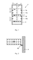
- FIG. 1 is a cross-sectional view of a valve according to a first embodiment of the invention
- FIG. 2 is an enlarged view of a portion of the valve shown in FIG. 1 ;
- FIG. 3 is a schematic view of the valve in a first position
- FIG. 4 is a schematic view of the valve in a second position
- FIG. 5 is a schematic view of the valve in a third position
- FIG. 6 is a schematic view of an oscillation of the valve
- FIG. 7 is a cross-sectional view of a valve according to a second embodiment of the invention.
- FIG. 8 is a cross-sectional view of a valve according to a third embodiment of the invention.
- FIG. 9 is an enlarged view of the valve shown in FIG. 8 , showing a bellows member in an expanded state
- FIG. 10 is an enlarged view of the valve shown in FIG. 8 , showing a bellows member in a compressed state;
- FIG. 11 is a perspective view of second type of valve in which the invention may be applied.
- FIG. 12 is a cross-sectional view of the valve shown in FIG. 11 ;
- FIG. 13 is a schematic view of a valve according to a fourth embodiment of the invention in a first position
- FIG. 14 is a schematic view of the valve shown in FIG. 13 in a second position
- FIG. 15 is a schematic view of the valve of FIG. 13 in a third position.
- FIG. 16 is a schematic view of the valve of FIG. 13 in an oscillation phase.
- FIG. 17 is a schematic view of a valve according to a fifth embodiment of the invention in a first position
- FIG. 18 is a schematic view of the valve shown in FIG. 17 in a second position
- FIG. 19 is a cross-sectional view of a valve according to another embodiment of the invention.
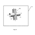
- FIG. 20 is a perspective view of a valve according to yet another embodiment of the invention.
- FIG. 1 shows a valve 2 according to a first embodiment of the invention.
- the valve is a directional spool-type valve.
- the valve 2 comprises a housing 4 in which a movable valve element 6 is disposed.
- the housing 4 defines a generally cylindrical chamber.
- a plurality (five are shown in FIG. 1 ) of ports, labeled A-E, are provided in the wall of the housing 4 .
- the ports A-E extend through the wall of the housing 4 and open into the chamber defined by the housing 4 .
- a plurality of seal portions are affixed to the housing 4 within the chamber.
- the seal portions are O-rings or other similar types of seals.
- the seal portions comprise an upper pair formed by a first upper seal portion 8 a and a second upper seal portion 8 b, and a lower pair formed by a first lower seal portion 10 a and a second lower seal portion 10 b.
- the first and second upper seal portions 8 a, 8 b are spaced from one another, as are the first and second lower seal portions 10 a, 10 b.
- the spacing between each of the first and second upper seal portions 8 a, 8 b and the first and second lower seal portions 10 a, 10 b is equal.
- the positions of the upper and lower pairs are offset from one another such that the upper and lower pairs are interleaved with one another. Specifically, the positions of the upper and lower pairs are offset such that the first lower seal portion 10 a is disposed between the first and second upper seal portions 8 a, 8 b.
- Port A is provided above the first upper seal portion 8 a.
- Port B is provided between the first upper seal portion 8 a and the first lower seal portion 10 a.
- Port C is provided between the first lower seal portion 10 a and the second upper seal portion 8 b.
- Port D is provided between the second upper seal portion 8 b and the second lower seal portion 10 b.
- Port E is provided below the second lower seal portion 10 b.
- ports A-E may all be located on one side of the housing or may be arranged in any combination of positions about the full circumference of the housing 4 .
- the movable valve element 6 which may be commonly referred to as a spool or piston, comprises a central stem 12 and a plurality of valve members (three are shown in FIG. 1 ), labeled 14 a - 14 c, which are provided on the stem 12 .
- the valve members comprise an upper valve member 14 a, a central valve member 14 b, and a lower valve member 14 c.
- valve members 14 a - 14 c are spaced along the stem 12 and are fixed relative to the stem 12 .
- the valve members 14 a - 14 c have a complementary shape to the cross-section of the chamber defined by the housing 4 . Therefore, in this embodiment, the valve members 14 a - 14 c are disc-shaped.
- the valve members 14 a - 14 c are sized so that they may not pass through the seal portions 8 , 10 .
- the seal portions 8 , 10 therefore act as stops which limit the movement of the valve element 6 .
- the valve members 14 a - 14 c have a complementary shape to the chamber, they are sized slightly smaller such that they do not ordinarily contact the inner surface of the wall of the housing 4 .
- the upper valve member 14 a is provided above the first upper seal portion 8 a and is configured to seal against an upper surface of the first upper seal portion 8 a.
- the central valve member 14 b is provided between the first lower seal portion 10 a and the second upper seal portion 8 b and is configured to seal against either a lower surface of the first lower seal portion 10 a or an upper surface of the second upper seal portion 8 b.
- the lower valve member 14 c is provided below the lower second seal portion 10 b and is configured to seal against a lower surface of the second lower seal portion 10 b. As described, the valve members 14 a - 14 c seal against the upper surfaces of the upper pair of seal portions 8 a, 8 b and against the lower surfaces of the lower pair of seal portions 10 a, 10 b.
- the seal portions 8 , 10 are deformable under force applied by the respective valve member. This mechanism will be described further below.
- the valve element 6 is translatable relative to the housing 4 so as to adjust the positions of the valve members 14 a - 14 c.
- the valve members 14 a - 14 c are sized so that they may not pass through the seal portions 8 , 10 . Accordingly, the seal portions 8 , 10 limit the movement of the valve element 6 .
- valve element 6 The positions of the valve element 6 will now be described with reference to the schematic illustrations provided in FIGS. 3 to 6 .
- ports A and E are shown as being provided at ends of the housing 4 , however they may be arranged as shown in FIG. 1 .
- FIG. 3 shows a first position of the valve element 6 in which the upper valve member 14 a is sealed against the upper surface of the first upper seal portion 8 a, the central valve member 14 b is sealed against the upper surface of the second upper seal portion 8 b, and the lower valve member 14 c is spaced from the lower surface of the second lower seal portion 10 b.
- ports B and C are in fluid communication with one another, and ports D and E are in fluid communication with one another.
- FIG. 4 shows a second position of the valve element 6 in which the upper valve member 14 a is spaced from the upper surface of the first upper seal portion 8 a, the central valve member 14 b is sealed against the lower surface of the first lower seal portion 10 a, and the lower valve member 14 c is sealed against the lower surface of the second lower seal portion 10 b.
- ports A and B are in fluid communication with one another, and ports C and D are in fluid communication with one another.
- FIG. 5 shows a third position of the valve element 6 which is midway between the first and second positions described previously.
- the upper valve member 14 a is spaced from the upper surface of the first upper seal portion 8 a
- the central valve member 14 b is spaced from both the lower surface of the first lower seal portion 10 a and the upper surface of the second upper seal portion 8 b
- the lower valve member 14 c is spaced from the lower surface of the second lower seal portion 10 b.
- the valve 2 is particularly suited to application in a cough assist device CAD (e.g., as shown in FIG. 19 ).
- the valve 2 is used to apply a positive pressure to a patient's lungs during an insufflation phase and to apply a negative pressure to the patient's lungs during an exsufflation phase. Between the exsufflation phase and the next insufflation phase, a short pause is provided in which no pressure is applied to the patient's lungs.
- the valve 2 is therefore configured to supply either a positive pressure, a negative pressure, or no pressure.
- the valve 2 is arranged so that port C is connected to the lungs of the patient. This may be via a mouthpiece or mask which is worn by the patient, or via a connection to a tracheotomy tube.
- Port B is connected to a source of positive air pressure, whereas port D is connected to a source of negative air pressure (although the reverse configuration may be used). Ports A and E vent to ambient pressure.
- the first position of the valve element 6 shown in FIG. 3 corresponds to the insufflation phase.
- the positive pressure provided at port B is in fluid communication with port C and thus air enters the lungs of the patient during the insufflation phase.
- the negative pressure provided at port D is sealed from port C and the patient by the sealing of the central valve member 14 b against the upper surface of the second upper seal portion 8 b.
- the negative pressure provided at port D instead vents to atmospheric pressure via port E.
- the second position of the valve element 6 shown in FIG. 4 corresponds to the exsufflation phase.
- the negative pressure provided at port D is in fluid communication with port C and thus extracts the air volume introduced during the insufflation phase from the lungs, and, along with it, any secretions.
- the positive pressure provided at port B is sealed from port C and the patient by the sealing of the central valve member 14 b against the lower surface of the first lower seal portion 10 a.
- the positive pressure provided at port B instead vents to atmospheric pressure via port A.
- the third position of the valve element 6 shown in FIG. 5 corresponds to the pause phase. In this position, both the positive pressure provided at port B and the negative pressure provided at port D vent to atmospheric pressure via ports A and E respectively. Consequently, no pressure is applied to port C and the patient.
- the pressure at port C may gradually increase by moving the valve element 6 from the (zero pressure) third position shown in FIG. 5 to the (fully open) first position shown in FIG. 3 .
- FIG. 6 shows an oscillation of the valve element 6 during the exsufflation phase.
- the valve element 6 oscillates between the (fully open) second position shown in FIG. 4 and a position which is slightly toward the (zero pressure) third position shown in FIG. 5 .
- This varies the pressure applied to port C.
- a corresponding oscillation may also be applied during the insufflation phase between the (fully open) first position shown in FIG. 3 and a position which is slightly toward the (zero pressure) third position shown in FIG. 5 .
- the amplitude and frequency of the oscillation may be set to enhance the removal of secretions from the lungs, whilst minimizing discomfort for the patient.
- the seal portions 8 , 10 are deformable under force applied by the respective valve member.
- the deformation of the seal portions 8 , 10 is able to counteract deviations in the positions of the valve members 14 a - 14 c and/or the seal portions 8 , 10 .
- the upper valve member 14 a and the central valve member 14 b may be affixed to the stem 12 such that they are spaced apart from one another by a distance which is different from that desired. Such deviations may result from manufacturing tolerances or thermal expansion or contraction of the components (particularly the stem 12 ), for example.
- the central valve member 14 b will contact the upper surface of the second upper seal portion 8 b prior to the upper valve member 14 a contacting the upper surface of the first upper seal portion 8 a.
- the upper valve member 14 a would be spaced from the upper surface of the first upper seal portion 8 a and thus would not be able to seal against the first upper seal portion 8 a. Consequently, air from port B would leak past the upper valve member 14 a to port A, thus reducing the air pressure delivered to port C.
- the second upper seal portion 8 b is able to deform under a force applied by the central valve member 14 b and thus can counteract the deviation in the distance between the upper valve member 14 a and the central valve member 14 b.
- the deformation of the second upper seal portion 8 b translates the upper surface of the second upper seal portion 8 b in the direction of movement of the valve element 6 . Consequently, the deformation of the second upper seal portion 8 b effectively increases the distance between the upper surface of the first upper seal portion 8 a and the upper surface of the second upper seal portion 8 b. This allows the upper valve member 14 a to be brought into contact with the upper surface of the first upper seal portion 8 a, and thus provides an effective seal between the upper valve member 14 a and the first upper seal portion 8 a, and between the central valve member 14 b and the second upper seal portion 8 b.
- the upper valve member 14 a will contact the upper surface of the first upper seal portion 8 a prior to the central valve member 14 b contacting the upper surface of the second upper seal portion 8 b.
- the first upper seal portion 8 a is able to deform under a force applied by the upper valve member 14 a and thus can counteract the deviation in the distance between the upper valve member 14 a and the central valve member 14 b.
- the deformation of the first upper seal portion 8 a translates the upper surface of the first upper seal portion 8 a in the direction of movement of the valve element 6 . Consequently, the deformation of the first upper seal portion 8 a effectively decreases the distance between the upper surface of the first upper seal portion 8 a and the upper surface of the second upper seal portion 8 b. This allows the central valve member 14 b to be brought into contact with the upper surface of the second upper seal portion 8 b, and thus provides an effective seal between the upper valve member 14 a and the first upper seal portion 8 a, and between the central valve member 14 b and the second upper seal portion 8 b.
- first and second lower seal portions 10 a, 10 b are deformable to counteract deviations in the distance between the central valve member 14 b and the lower valve member 14 c.
- valve element 6 is translated relative to the housing 4 using a linear actuator, such as a voice coil linear motor.
- a linear actuator such as a voice coil linear motor.
- the valve members 14 a - 14 c are sized such that they do not contact the inner surface of the housing 4 . Consequently, very little resistance is provided against the movement of the valve element 6 until the valve members 14 a - 14 c contact the seal portions 8 , 10 .
- the actuator may translate the valve element 6 until a predetermined resistive force is offered by the seal portions 8 , 10 .
- the predetermined resistive force may be set so as to ensure that, in the first position, the upper and central valve members 14 a, 14 b are both sealed against the first and second upper seal portions 8 a, 8 b and that, in the second position, the central and lower valve members 14 b, 14 c are both sealed against the first and second lower seal portions 10 a, 10 b.
- a valve 102 according to a second embodiment of the invention will now be described with reference to FIG. 7 .
- the valve 102 has a similar construction to the valve 2 . Consequently, the following description of the valve 102 will focus primarily on the differences between the first and second embodiments.
- the valve 102 comprises a housing 104 in which a movable valve element 106 is disposed.
- the housing 104 is identical to the housing 4 of the first embodiment and comprises ports A-E provided in the wall of the housing 104 and a plurality of seal portions affixed to the housing 104 .
- the seal portions comprise an upper pair formed by a first upper seal portion 108 a and a second upper seal portion 108 b, and a lower pair formed by a first lower seal portion 110 a and a second lower seal portion 110 b.
- the valve element 106 comprises a central stem 112 and a plurality of valve members 114 a - 114 c, which are provided on the stem 12 .
- the upper and lower valve members 114 a, 114 c are much thinner than the central valve member 114 b. Consequently, the upper and lower valve members 114 a and 114 c are flexible and are able to deform under force.
- valve members 114 a - 114 c are sized so that they may not pass through the seal portions.
- the seal portions therefore act as stops which limit the movement of the valve element 106 .
- the deformation of the upper and lower valve members 114 a, 114 c is able to counteract deviations in the positions of the valve members 114 a - 114 c and/or the seal portions 108 , 110 .
- the upper valve member 114 a will contact the upper surface of the first upper seal portion 8 a prior to the central valve member 114 b contacting the upper surface of the second upper seal portion 108 b.
- the central valve member 114 b would be spaced from the upper surface of the second upper seal portion 108 b and thus would not be able to seal against the second upper seal portion 108 b. Consequently, ports B and C would be exposed to the negative pressure of port D.
- the upper valve member 114 a is able to deform under a force applied by the movement of the upper valve member 114 a relative to the first upper seal portion 108 a, and thus can counteract the deviation in the distance between the upper valve member 114 a and the central valve member 114 b.
- the upper valve member 114 a assumes a substantially planar profile in which a radially inner portion adjacent the stem 112 is aligned with a radially outer periphery of the upper valve member 114 a.
- the movement of the upper valve member 114 a relative to the first upper seal portion 108 a causes the upper valve member 114 a to be deformed such that the outer periphery of the upper valve member 114 a is no longer aligned with the radially inner portion.
- the outer periphery of the upper valve member 114 a is deflected away from the central valve member 114 b.
- the lower valve member 114 c is deformable to counteract deviations in the distance between the central valve member 114 b and the lower valve member 114 c.
- valve member 114 b may alternatively or additionally be deformable.
- the central valve member 114 b may be deformed either toward the upper valve member 114 a (in the first position) or toward the lower valve member 114 c (in the second position). Accordingly, the deformation of the central valve member 114 b is able to counteract deviations which result in the distance between the central valve member 114 b and the upper or lower valve member 114 a, 114 c being greater than desired. This would otherwise cause the upper or lower valve member 114 a, 114 c to be spaced from the upper surface of the first upper seal portion 108 a or the lower surface of the second lower seal portion 110 b, respectively.
- the spacing between the central valve member 114 b and the upper valve member 114 a, and between the central valve member 114 b and the lower valve member 114 c may be configured such that an effective seal is formed between the upper valve member 114 a and the first upper seal portion 108 a, and between the central valve member 114 b and the second upper seal portion 108 b over the range of anticipated deviations.
- the spacing between the central valve member 114 b and the upper valve member 114 a, and between the central valve member 114 b and the lower valve member 114 c is set such that under the maximum anticipated deviation (i.e. based on manufacturing tolerances, thermal expansion or contraction, etc.) which results in the spacing being smaller than desired, an effective seal is still formed between the upper valve member 114 a and the first upper seal portion 108 a, and between the central valve member 114 b and the second upper seal portion 108 b.
- the central valve member 114 b may be subject to only minimal resistive force by the second upper seal portion 108 b (in the first position) or the first lower seal portion 110 a (in the second position) such that the central valve member 114 b is substantially underformed or only slightly deformed. Consequently, all other deviations from the desired spacing result in the central valve member 114 b being deformed to a greater extent.
- the spacing between the central valve member 114 b and the upper valve member 114 a, and between the central valve member 114 b and the lower valve member 114 c is set such that under the maximum anticipated deviation (i.e.
- the upper valve member 114 a in the first position or the lower valve member 114 c (in the second position) may be subject to only minimal resistive force by the first upper seal portion 108 a or the second lower seal portion 110 b respectively such that the upper or lower valve member 114 a, 114 c is substantially undeformed or only slightly deformed. Consequently, all other deviations from the desired spacing result in the upper or lower valve member 114 a, 114 c being deformed to a greater extent.
- valve members 114 a - 114 c are again able to counteract these deviations so as to ensure that an effective seal is provided between the valve members 114 a - 114 c and the seal portions 108 , 110 .
- the deformation of the central valve member 114 b is able to counteract deviations which result in the upper surfaces of the first and second upper seal portions 108 a, 108 b and the lower surfaces of the first and second lower seal portions 110 a, 110 b being respectively spaced closer to one another than desired.
- the deformation of the upper and lower valve members 114 a, 114 c is able to counteract deviations which result in the upper surfaces of the first and second upper seal portions 108 a, 108 b and the lower surfaces of the first and second lower seal portions 110 a, 110 b being respectively spaced further from one another than desired.
- the seal portions 108 , 110 may also be deformable under force applied by the respective valve member.
- the combined deformation of the seal portions 108 , 110 and the valve members 114 a - 114 c can counteract larger deviations in the positions of the seal portions 108 , 110 and the valve members 114 a - 114 c.
- the deformable valve members may be pre-curved such that they are deformed towards a planar configuration. This may increase the resistance of the valve members to deformation and thus provide a bias force which acts to return the valve element 106 to the third position from the first and/or second positions.
- a valve 202 according to a third embodiment of the invention will now be described with reference to FIG. 8 .
- the valve 202 has a similar construction to the valve 2 . Consequently, the following description of the valve 202 will focus primarily on the differences between the first and second embodiments.
- the valve 202 comprises a housing 204 in which a movable valve element 206 is disposed.
- the housing 204 is similar to the housing 4 of the first embodiment and comprises ports A-E provided in the wall of the housing 204 and a plurality of seal portions affixed to the housing 204 .
- the seal portions comprise an upper pair formed by a first upper seal portion 208 a and a second upper seal portion 208 b, and a lower pair formed by a first lower seal portion 210 a and a second lower seal portion 210 b.
- the second upper seal portion 208 b and the first lower seal portion 210 a are each formed by an O-ring (or another similar type of seal)
- the first upper seal portion 208 a and the second lower seal portion 208 b are each formed by a bellows member.
- the bellows member of the first upper seal portion 208 a is connected at one end to the upper valve member 214 a and at the other end to the inner surface of the housing 204 at a position which is between ports A and B.
- the bellows member of the second lower seal portion 210 b is connected at one end to the lower valve member 214 c and at the other end to the inner surface of the housing 204 at a position which is between ports D and E.
- Each of the bellows members is constructed from a tubular length of flexible material, such as rubber, which is formed into a series of convolutions.
- the convolutions allow the length of the bellows member to increase or decrease.
- the bellows member may taper slightly such that the end of the bellows member which is connected to the housing 204 has a greater diameter than the end which is connected to the upper or lower valve member 214 a, 214 c.
- FIG. 9 shows the bellows member of the second lower seal portion 210 b when the valve element 206 is in the first position.
- the lower valve member 214 c is spaced away from port D and the position at which the bellows member connects to the housing 204 . Accordingly, the bellows member is in an expanded state.
- a plurality of holes 216 are formed in each of the convolutions of the bellows member.
- the holes 216 pass entirely through the thickness of the material of the bellows member and thus, in the expanded state, enable fluid communication across the bellows member (i.e. from the inside of the bellows member to the outside of the bellows member, and vice versa).
- FIG. 10 shows the bellows member of the first upper seal portion 208 a when the valve element 206 is in the first position.
- the upper valve member 214 a is adjacent port B and the position at which the bellows member connects to the housing 204 . Accordingly, the bellows member is in a contracted state.
- the holes 216 of adjacent convolutions are offset from one another. Consequently, in the contracted state, the holes 216 of each convolution are covered by the surface of an adjacent convolution. Accordingly, in the contracted state, fluid communication is not permitted across the bellows member.
- valve element 206 For clarity, the arrangement of valve element 206 and the permitted flow passages will now be described for the first, second and third positions of the valve element 206 .
- the upper valve member 214 a is sealed against the housing 204 since the bellows member of the first upper seal portion 208 a is in the contracted state, the central valve member 214 b is sealed against the upper surface of the second upper seal portion 208 b, and the lower valve member 214 c is not sealed against the housing 204 since the bellows member of the second lower seal portion 210 b is in the expanded state.
- ports B and C are in fluid communication with one another, and ports D and E are in fluid communication with one another via the holes 216 in the bellows member of the second lower seal portion 210 b.
- ports A and B are not in fluid communication with one another since they are sealed from one another by the bellows member of the first upper seal portion 208 a.
- the upper valve member 214 a is not sealed against the housing 204 since the bellows member of the first upper seal portion 208 a is in the expanded state, the central valve member 214 b is sealed against the lower surface of the first lower seal portion 210 a, and the lower valve member 214 c is sealed against the housing 204 since the bellows member of the second lower seal portion 210 b is in the contracted state.
- ports A and B are in fluid communication with one another via the holes 216 in the bellows member of the first upper seal portion 208 a, and ports C and D are in fluid communication with one another.
- ports D and E are not in fluid communication with one another since they are sealed from one another by the bellows member of the second lower seal portion 210 b.
- the upper valve member 214 a and the lower valve member 214 c are not sealed against the housing 204 since the bellows members of the first upper seal portion 208 a and the second lower seal portion 210 b are in a partially expanded state.
- the holes 216 are sufficiently unobstructed so as to allow fluid communication across the bellows members.
- the central valve member 214 b is spaced from both the lower surface of the first lower seal portion 210 a and the upper surface of second upper seal portion 208 b.
- the holes 216 of the bellows member are obstructed and thus the bellows member forms a seal.
- An adequate seal is provided over a range of contracted states (referred to as the sealed range of the bellows member).
- the effective length of the bellows member may vary whilst maintaining an adequate seal.
- the bellows members of the first upper seal portion 208 a and the second lower seal portion 210 b are thus able to deform over the sealed range so as to counteract deviations in the positions of the valve members 214 a - 214 c and/or the seal portions 208 , 210 .
- first upper seal portion 208 a and the second lower seal portion 210 b have been described as being formed by bellows members, the second upper seal portion 208 b and the first lower seal portion 210 a may alternatively or additionally be formed by bellows.
- the bellows members may be replaced by a tubular seal formed of a stretchable material having a plurality of holes formed therethrough. In the contracted state the holes are closed and in the expanded state the holes are open.
- the size of the holes in the stretchable material may vary proportionally with the position of the valve element 206 . Therefore, the resistance of the stretchable material to fluid flow can be configured to vary with the position of the valve element 206 .
- the stretchable material may be configured so that the resistance to fluid flow varies linearly with the position of the valve element 206 .
- FIGS. 11 and 12 show a valve 302 according to a fourth embodiment of the invention.
- the valve 302 of the fourth embodiment differs from the previous embodiments in that the inventive concept is applied in a rotational valve, such as a butterfly valve.
- the valve 302 comprises a housing 304 in which a movable valve element 306 is disposed.
- the housing 304 is formed by four tubular conduits which all lie in the same plane and which are joined at the centre of the housing 304 .
- the end of each of the conduits is mitred at 90° (referred to herein as an end quadrant) so that the conduits can be arranged in a cruciform and adjoin one another to form a fluid-tight housing.
- the four tubular conduits define ports A-D. Ports A and C are positioned opposite one another and ports B and D are positioned opposite one another.
- the end quadrants of the four conduits define a generally spherical chamber which will be described further below.
- a plurality of seal portions are affixed to the housing 304 within the chamber (see FIGS. 13 and 14 ).
- the seal portions comprise a right-diagonal pair formed by a first right-diagonal seal portion 308 a and a second right-diagonal seal portion 308 b, and a left-diagonal pair formed by a first left-diagonal seal portion 310 a and a second left-diagonal seal portion 310 b.
- the first right-diagonal seal portion 308 a is substantially semi-circular and is connected to the housing 304 along the intersection between the end quadrants of ports A and B. The first right-diagonal seal portion 308 a therefore seals port A from port B.
- the second right-diagonal seal portion 308 b is substantially semi-circular and is connected to the housing 304 along the intersection between the end quadrants of ports C and D. The second right-diagonal seal portion 308 b therefore seals port C from port D.
- the right-diagonal pair of seal portions 308 thus separates ports B and C from ports A and D.
- the first left-diagonal seal portion 310 a is substantially semi-circular and is connected to the housing 304 along the intersection between the end quadrants of ports A and D. The first left-diagonal seal portion 310 a therefore seals port A from port D.
- the second left-diagonal seal portion 310 b is substantially semi-circular and is connected to the housing 304 along the intersection between the end quadrants of ports B and C. The second left-diagonal seal portion 310 b therefore seals port B from port C.
- the left-diagonal pair of seal portions 310 thus separates ports A and B from ports C and D.
- the right-diagonal pair of seal portions 308 and the left-diagonal pair of seal portions 310 are offset from one another by an angular distance of approximately 90° and intersect one another at the centre of the chamber.
- the movable valve element 306 comprises a central stem 312 to which a first valve member 314 a and a second valve member 314 b are coupled.
- Each of the first and second valve members 314 a, 314 b is a substantially semi-circular disc.
- the first and second valve members 314 a, 314 b thus have a complementary shape to the cross-section of the chamber defined by the end quadrants of the conduits.
- the first valve member 314 a and the second valve member 314 b are coupled to the stem 312 at diametrically opposed positions.
- the first and second valve members 314 a, 314 b are arranged so as to extend from the stem 312 in directions which are parallel but offset from one another, as shown in FIG. 12 .
- the first and second valve members 314 a, 314 b are sized so that they may not pass through the seal portions 308 , 310 .
- the seal portions 308 , 310 therefore act as stops which limit the movement of the valve element 306 .
- the first and second valve members 314 a, 314 b have a complementary shape to the chamber, they are sized slightly smaller such that they do not ordinarily contact the inner surface of the wall of the housing 314 .
- the positions of the first and second valve members 314 a, 314 b will now be described with reference to the seal portions 308 , 310 .
- the first valve member 314 a is provided between the first right-diagonal seal portion 308 a and the second left-diagonal seal portion 310 b and is configured to seal against either the first right-diagonal seal portion 308 a or the second left-diagonal seal portion 310 b.
- the first valve member 314 a is therefore permitted to move within the end quadrant of port B.
- the second valve member 314 b is provided between the second right-diagonal seal portion 308 b and the first left-diagonal seal portion 310 a and is configured to seal against either the second right-diagonal seal portion 308 b or the first left-diagonal seal portion 310 a. The second valve member 314 b is therefore permitted to move within the end quadrant of port D.
- the valve element 306 is rotatable relative to the housing 304 so as to adjust the positions of the first and second valve members 314 a, 314 b.
- the valve members 314 a, 314 b are sized so that they may not pass through the seal portions 308 , 310 . Accordingly, the seal portions 308 , 310 limit the movement of the valve element 306 .
- valve element 306 The positions of the valve element 306 will now be described with reference to the schematic illustrations provided in FIGS. 13 to 16 .
- FIG. 13 shows a first position of the valve element 306 in which the first valve member 314 a is sealed against the first right-diagonal seal portion 308 a, and the second valve member 314 b is sealed against the second right-diagonal seal portion 308 b.
- the first and second valve members 314 a, 314 b seal against opposing sides of the first and second right-diagonal seal portions 308 a, 308 b.
- ports A and D are in fluid communication with one another, and ports B and C are in fluid communication with one another.
- the first and second valve members 314 a, 314 b thus separate ports A and D from ports B and C.
- FIG. 14 shows a second position of the valve element 306 in which the first valve member 314 a is sealed against the second left-diagonal seal portion 310 b, and the second valve member 314 b is sealed against the first left-diagonal seal portion 310 a.
- the first and second valve members 314 a, 314 b seal against opposing sides of the first and second left-diagonal seal portions 310 a, 310 b.
- ports A and B are in fluid communication with one another, and ports C and D are in fluid communication with one another.
- the first and second valve members 314 a, 314 b thus separate ports A and B from ports C and D.
- FIG. 15 shows a third position of the valve element 306 which is midway between the first and second positions described previously.
- the first valve member 314 a is spaced from both the first right-diagonal seal portion 308 a and the second left-diagonal seal portion 310 b
- the second valve member 314 b is spaced from both the second right-diagonal seal portion 308 b and the first left-diagonal seal portion 310 a.
- the valve 302 is particularly suited to application in a cough assist device.
- CAD e.g., as shown in FIG. 20
- the valve 302 is used to apply a positive pressure to a patient's lungs during an insufflation phase and to apply a negative pressure to the patient's lungs during an exsufflation phase. Between the exsufflation phase and the next insufflation phase, a short pause is provided in which no pressure is applied to the patient's lungs.
- the valve 302 is therefore configured to supply either a positive pressure, a negative pressure, or no pressure.
- the valve 302 is arranged so that port C is connected to the lungs of the patient. This may be via a mouthpiece or mask which is worn by the patient, or via a connection to a tracheotomy tube.
- Port B is connected to a source of positive air pressure, whereas port D is connected to a source of negative air pressure (although the reverse configuration may be used). Port A vents to ambient pressure.
- the first position of the valve element 306 shown in FIG. 13 corresponds to the insufflation phase.
- the positive pressure provided at port B is in fluid communication with port C and thus air enters the lungs of the patient during the insufflation phase.
- the negative pressure provided at port D is sealed from port C and the patient by the sealing of the second valve member 314 b against the second right-diagonal seal portion 308 b and the sealing of the first valve member 314 a against the first right-diagonal seal portion 308 a.
- the negative pressure provided at port D instead vents to atmospheric pressure via port A.
- the second position of the valve element 306 shown in FIG. 14 corresponds to the exsufflation phase.
- the negative pressure provided at port D is in fluid communication with port C and thus extracts the air volume introduced during the insufflation phase from the lungs, and, along with it, any secretions.
- the positive pressure provided at port B is sealed from port C and the patient by the sealing of the first valve member 314 a against the second left-diagonal seal portion 310 b and the sealing of the second valve member 314 b against the first left-diagonal seal portion 310 a.
- the positive pressure provided at port B instead vents to atmospheric pressure via port A.
- the third position of the valve element 306 shown in FIG. 15 corresponds to the pause phase. In this position, both the positive pressure provided at port B and the negative pressure provided at port D vent to atmospheric pressure via port A. Consequently, no pressure is applied to port C and the patient.
- the pressure at port C may gradually increase by moving the valve element 306 from the (zero pressure) third position shown in FIG. 15 to the (fully open) first position shown in FIG. 13 .
- FIG. 16 shows an oscillation of the valve element 306 during the insufflation phase.
- the valve element 306 oscillates between the (fully open) first position shown in FIG. 13 and a position which is slightly toward the (zero pressure) third position shown in FIG. 15 .
- This varies the pressure applied to port C.
- a corresponding oscillation may also be applied during the exsufflation phase between the (fully open) second position shown in FIG. 14 and a position which is slightly toward the (zero pressure) third position shown in FIG. 15 .
- the amplitude and frequency of the oscillation may be set to enhance the removal of secretions from the lungs, whilst minimizing discomfort for the patient.
- the seal portions 308 , 310 are deformable under force applied by the first and second valve members 314 a, 314 b.
- the deformation of the seal portions 308 , 310 is able to counteract deviations in the positions of the valve members 314 a, 314 b and/or the seal portions 308 , 310 .
- first and second valve members 314 a, 314 b may be affixed to the stem 312 such that they are spaced apart from one another by an angular distance which is different from that desired (i.e. where the first and second valve members 314 a, 314 b are not parallel with one another). Such deviations may result from manufacturing tolerances or distortion of the valve members, for example.
- the second valve member 314 b will contact the second right-diagonal seal portion 308 b prior to the first valve member 314 a contacting the first right-diagonal seal portion 308 a.
- the first valve member 314 a would be spaced from the first right-diagonal seal portion 308 a and thus would not be able to seal against the first right-diagonal seal portion 308 a. Consequently, air from port B would leak past the first valve member 314 a to port A, thus reducing the air pressure delivered to port C.
- the second right-diagonal seal portion 308 b is able to deform under a force applied by the second valve member 314 b and thus can counteract the deviation in the distance between the first and second valve members 314 a, 314 b.
- the deformation of the second right-diagonal seal portion 308 b translates the opposing surface of the second right-diagonal seal portion 308 b in the direction of rotation of the valve element 306 . Consequently, the deformation of the second right-diagonal seal portion 308 b effectively increases the angular distance (measured in the same manner as for the first and second valve members 314 a, 314 b ) between the opposing surface of the first right-diagonal seal portion 308 a and the opposing surface of second right-diagonal seal portion 308 b.
- first valve member 314 a This allows the first valve member 314 a to be brought into contact with the surface of the first right-diagonal seal portion 308 a, and thus provides an effective seal between the first valve member 314 a and the first right-diagonal seal portion 308 a, and between the second valve member 314 b and the second right-diagonal seal portion 308 b.
- the first valve member 314 a will contact the first right-diagonal seal portion 308 a prior to the second valve member 314 b contacting the second right-diagonal seal portion 308 b.
- the first right-diagonal seal portion 308 a is able to deform under a force applied by the first valve member 314 a and thus can counteract the deviation in the distance between the first valve member 314 a and the second valve member 314 b.
- the deformation of the first right-diagonal seal portion 308 a translates the opposing surface of the first right-diagonal seal portion 308 a in the direction of rotation of the valve element 306 . Consequently, the deformation of the first right-diagonal seal portion 08 a effectively decreases the distance between the opposing surface of the first right-diagonal seal portion 308 a and the opposing surface of the second right-diagonal seal portion 308 b.
- first and second left-diagonal seal portions 310 a, 310 b are deformable to counteract deviations in the angular distance in the direction of movement (from the first position to the second position) between the first valve member 314 a and the second valve member 314 b (i.e. in an clockwise direction from the first valve member 314 a to the second valve member 314 b ) when the valve element 306 is in the second position.
- the valve element 306 is rotated relative to the housing 304 using a rotary actuator, such as a voice coil rotary motor. This provides extremely quick and accurate rotation of the valve element 306 between the operating positions.
- a rotary actuator such as a voice coil rotary motor.
- the valve members 314 a, 314 b are sized such that they do not contact the inner surface of the housing 304 . Consequently, very little resistance is provided against the movement of the valve element 306 until the valve members 314 a, 314 b contact the seal portions 308 , 310 .
- the actuator may rotate the valve element 306 until a predetermined resistive force is offered by the right-diagonal or left-diagonal seal portions 308 , 310 .
- the predetermined resistive force may be set so as to ensure that, in the first position, the first and second valve members 314 a, 314 b are both sealed against the first and second right-diagonal seal portions 308 a, 308 b and that, in the second position, the first and second valve members 314 a, 314 b are both sealed against the first and second left-diagonal seal portions 310 a, 310 b.
- first and second valve members 314 a, 314 b have been described as being offset from one another, they may alternatively be aligned with one another and the seal portions may instead be offset from one another.
- seal portions 308 , 310 have been described as being located at the intersection of the adjacent ports, they may be located on either side of the intersection.
- FIGS. 17 and 18 show a valve 402 according to a fifth embodiment of the invention.
- the valve 402 is a rotational valve, such as a butterfly valve.
- the valve 402 corresponds to a rotational implementation of the second embodiment described previously.
- the valve 402 has a similar construction to the valve 302 . Consequently, the following description of the valve 402 will focus primarily on the differences between the fourth and fifth embodiments.
- valve 302 comprises a housing 404 in which a movable valve element 406 is disposed.
- FIG. 17 shows the valve element 406 in the first position (corresponding to the insufflation phase), whereas FIG. 18 shows the valve element 406 in the second position (corresponding to the exsufflation phase).
- the valve element 406 can also assume the third position shown in FIG. 15 for the valve 302 (corresponding to the pause phase) and may oscillate as shown in FIG. 16 for the valve 302 .
- the housing 404 is identical to the housing 304 of the fourth embodiment and comprises ports A-D defined by four tubular conduits and a plurality of seal portions affixed to the housing 404 within the chamber.
- the seal portions comprise a right-diagonal pair formed by a first right-diagonal seal portion 408 a and a second right-diagonal seal portion 408 b, and a left-diagonal pair formed by a first left-diagonal seal portion 410 a and a second left-diagonal seal portion 410 b.
- valve element 406 comprises a central stem 412 to which a first valve member 414 a and a second valve member 414 b are coupled.
- first and second valve members 414 a, 414 b are thinner and thus are able to flex and deform under force.
- the first and second valve members 414 a, 414 b are sized so that they may not pass through the seal portions 408 , 410 .
- the seal portions 408 , 410 therefore act as stops which limit the movement of the valve element 406 .
- the deformation of the first and second valve members 414 a, 414 b is able to counteract deviations in the positions of the valve members 414 a, 414 c and/or the seal portions 408 , 410 .
- the second valve member 414 b will contact the second right-diagonal seal portion 408 b prior to the first valve member 414 a contacting the first right-diagonal seal portion 408 a.
- the first valve member 414 a would be spaced from the first right-diagonal seal portion 408 a and thus would not be able to seal against the first right-diagonal seal portion 408 a. Consequently, air from port B would leak past the first valve member 414 a to port A, thus reducing the air pressure delivered to port C.
- the second valve member 414 b is able to deform under a force applied by the rotation of the valve element 406 and thus can counteract the deviation in the distance between the first and second valve members 414 a, 414 b.
- the second valve member 414 b assumes a substantially planar profile in which a radially inner portion adjacent the stem 412 is aligned with a radially outer periphery of the second valve member 414 b.
- the movement of the second valve member 414 b relative to the second right-diagonal seal portion 408 b causes the second valve member 414 b to be deformed such that the outer periphery of the second valve member 414 b is no longer aligned with the radially inner portion.
- the outer periphery of the second valve member 414 b is deflected away from the second right-diagonal seal portion 408 b toward the first left-diagonal seal portion 410 a.
- the first valve member 414 a will contact the first right-diagonal seal portion 408 a prior to the second valve member 414 b contacting the second right-diagonal seal portion 408 b.
- the first valve member 414 a assumes a substantially planar profile in which a radially inner portion adjacent the stem 412 is aligned with a radially outer periphery of the first valve member 414 a.
- the first valve member 414 a is able to deform under a force applied by the rotation of the valve element 406 and thus can counteract the deviation in the distance between the first and second valve members 414 a, 414 b.
- the movement of the first valve member 414 a relative to the first right-diagonal seal portion 408 a causes the first valve member 414 a to be deformed such that the outer periphery of the first valve member 414 a is no longer aligned with the radially inner portion.
- the outer periphery of the first valve member 414 a is deflected away from the first right-diagonal seal portion 408 a toward the second left-diagonal seal portion 410 b.
- first and second valve members 414 a, 414 b are deformable to counteract deviations in the distance between the first valve member 414 a and the second valve member 414 b when the valve element 406 is in the second position.
- first and second valve members 414 a, 414 b have been described as being flexible, only one of the first and second valve members 414 a, 414 b need be so.
- the deformation of the first valve member 414 a is able to counteract deviations which result in the angular distance in the direction of movement between the first valve member 414 a and the second valve member 414 b being smaller than desired.
- the deformation of the second valve member 414 b is able to counteract deviations which result in the angular distance in the direction of movement between the first valve member 414 a and the second valve member 414 b being greater than desired.
- the angular distance between the first and second valve members 414 a, 414 b may be configured such that an effective seal is formed between the first valve member 414 a and the first right-diagonal seal portion 408 a or the second left-diagonal seal portion 410 b, and between the second valve member 414 b and the second right-diagonal seal portion 408 b or the first left-diagonal seal portion 410 a over the range of anticipated deviations.
- the spacing between the first valve member 414 a and the second valve member 414 b is set such that under the maximum anticipated deviation which results in the spacing being greater than desired, an effective seal is still formed between the first valve member 414 a and the first right-diagonal seal portion 408 a or the second left-diagonal seal portion 410 b, and between the second valve member 414 b and the second right-diagonal seal portion 408 b or the first left-diagonal seal portion 410 a.
- the first valve member 414 a may be subject to only minimal resistive force by the first right-diagonal seal portion 408 a (in the first position) or the second left-diagonal seal portion 410 b (in the second position) such that the second valve member 414 a is substantially undeformed or only slightly deformed. Consequently, all other deviations from the desired spacing result in the first valve member 414 a being deformed to a greater extent.
- the spacing between the first valve member 414 a and the second valve member 414 b is set such that under the maximum anticipated deviation which results in the spacing being smaller than desired, an effective seal is still formed between the first valve member 414 a and the first right-diagonal seal portion 408 a or the second left-diagonal seal portion 410 b, and between the second valve member 414 b and the second right-diagonal seal portion 408 b or the first left-diagonal seal portion 410 a.
- the second valve member 414 b may be subject to only minimal resistive force by the second right-diagonal seal portion 408 b (in the first position) or the first left-diagonal seal portion 410 a (in the second position) such that the second valve member 414 b is substantially undeformed or only slightly deformed. Consequently, all other deviations from the desired spacing result in the second valve member 414 b being deformed to a greater extent.
- valve members 414 a, 414 b are again able to counteract these deviations so as to ensure that an effective seal is provided between the valve members 414 a, 414 b and the seal portions 408 , 410 .
- the deformation of the first valve member 414 b is able to counteract deviations which result in the opposing surfaces of the first and second right-diagonal seal portions 408 a, 408 b and the opposing surfaces of the first and second left-diagonal seal portions 410 a, 410 b being respectively spaced further from one another than desired.
- the deformation of the second valve member 414 b is able to counteract deviations which result in the opposing surfaces of the first and second right-diagonal seal portions 408 a, 408 b and the opposing surfaces of the first and second left-diagonal seal portions 410 a, 410 b being respectively spaced closed to one another than desired.
- the seal portions 408 , 410 may also be deformable under force applied by the respective valve member.
- the combined deformation of the seal portions 408 , 410 and the valve members 414 a, 414 b can counteract larger deviations in the positions of the seal portions 408 , 410 and the valve members 414 a, 414 b.
- first and second valve members 414 a, 414 b may both be deformed when in the first and second positions. However, the first and second valve members 414 a, 414 b may be deformed to different extents in order to ensure proper sealing of both the first and second valve members 414 a, 414 b.
- a bellows member similar to that described in the third embodiment may be implemented in the rotational valves 302 , 402 .
- one or more of the left-diagonal seal portions 308 , 408 and/or the right-diagonal seal portions 310 , 410 may comprise a bellows member.
- the bellows member may be a single layer of material having a series of convolutions, each provided with a plurality of holes. The bellows member may be drawn across the end quadrant as the valve member moves between the first and second positions.
- a stretchable material similar to that described previously may be implemented in the rotational valves 302 , 402 .
- valve members In the first, second and third embodiments, only two valve members may be used to achieve the same effect. Where only two valve members are used, these are located between the first upper seal portion and the first lower seal portion, and between the second upper seal portion and the second lower seal portion respectively. The positions of the seal portions may differ from those shown in order to accommodate the valve members on either side of ports B and D.
- the deformation of the seal portions and/or the valve members is preferably elastic. Accordingly, the deformation provides a bias force which acts to return the valve element to the third position.
- some plastic deformation of the seal portions and the valve members may be acceptable in certain applications.
- first and second seal portions of the right-diagonal and/or left-diagonal pair may be a single continuous or discontinuous seal. Nevertheless, the first and second seal portions are described as separate portions since the valve members seal against opposite surfaces of the seal portions.
- valve element Although the movable valve elements have been described as being actuated mechanically, it may also be possible to move the valve element using pneumatic or hydraulic actuation.
- inventive concepts described herein may be applied in valves having any number of ports and is not limited to the specific embodiments described and shown.
- the invention may be implemented in rotational valves having only two ports.
- a rotational valve may be formed by a tubular housing having a rotational valve element disposed therein.
- the valve element may have a first position in which the two ports are separated by the valve members and a second position where the valve members are aligned with the direction of fluid flow and thus allow fluid communication between the two ports.
- valve members and seal portions Whilst the valve members and seal portions have been described as being deformed under the movement of the valve element, this need not be the case and the valve members and seal portions may be deformed by an external influence which deflects the seal portion and the respective valve member towards one another.
- one or more of the valve members may be formed from a shape memory alloy which when heated deforms to a different shape (i.e., its original, cold-forged shape). Therefore, where the valve member does not seal with the seal portion, the valve member can be heated such that it deforms and causes the valve member to seal with the seal portion.
- a similar arrangement may be used to cause the seal portion to move towards the valve member. It should be appreciated that various other arrangements may be used to deform the valve members and seal portions.
- valves of the invention are well suited to applications which require high flow, but low pressure.
Landscapes
- Engineering & Computer Science (AREA)
- Health & Medical Sciences (AREA)
- General Engineering & Computer Science (AREA)
- Mechanical Engineering (AREA)
- Heart & Thoracic Surgery (AREA)
- Anesthesiology (AREA)
- Hematology (AREA)
- Life Sciences & Earth Sciences (AREA)
- Animal Behavior & Ethology (AREA)
- General Health & Medical Sciences (AREA)
- Public Health (AREA)
- Veterinary Medicine (AREA)
- Biomedical Technology (AREA)
- Pulmonology (AREA)
- Emergency Medicine (AREA)
- Multiple-Way Valves (AREA)
Priority Applications (1)
| Application Number | Priority Date | Filing Date | Title |
|---|---|---|---|
| US14/772,244 US10213575B2 (en) | 2013-03-07 | 2014-01-31 | Valve |
Applications Claiming Priority (3)
| Application Number | Priority Date | Filing Date | Title |
|---|---|---|---|
| US201361773847P | 2013-03-07 | 2013-03-07 | |
| US14/772,244 US10213575B2 (en) | 2013-03-07 | 2014-01-31 | Valve |
| PCT/IB2014/058695 WO2014135997A1 (en) | 2013-03-07 | 2014-01-31 | A valve. |
Publications (2)
| Publication Number | Publication Date |
|---|---|
| US20160001033A1 US20160001033A1 (en) | 2016-01-07 |
| US10213575B2 true US10213575B2 (en) | 2019-02-26 |
Family
ID=50159312
Family Applications (1)
| Application Number | Title | Priority Date | Filing Date |
|---|---|---|---|
| US14/772,244 Active 2035-10-12 US10213575B2 (en) | 2013-03-07 | 2014-01-31 | Valve |
Country Status (5)
| Country | Link |
|---|---|
| US (1) | US10213575B2 (enExample) |
| EP (1) | EP2964314B1 (enExample) |
| JP (1) | JP2016508810A (enExample) |
| CN (1) | CN105007977B (enExample) |
| WO (1) | WO2014135997A1 (enExample) |
Families Citing this family (18)
| Publication number | Priority date | Publication date | Assignee | Title |
|---|---|---|---|---|
| US9539406B2 (en) * | 2013-09-10 | 2017-01-10 | General Electric Company | Interface device and method for supplying gas flow for subject breathing and apparatus for supplying anesthetic agent to the interface device |
| CN107106019B (zh) | 2014-10-31 | 2020-06-05 | 皇家飞利浦有限公司 | 控制增强的咳嗽流期间的压力 |
| US10315002B2 (en) * | 2015-03-24 | 2019-06-11 | Ventec Life Systems, Inc. | Ventilator with integrated oxygen production |
| US10518048B2 (en) * | 2015-07-31 | 2019-12-31 | Hill-Rom Services, PTE Ltd. | Coordinated control of HFCWO and cough assist devices |
| EP3525872B1 (en) * | 2016-10-17 | 2020-09-02 | Bayer Healthcare LLC | Fluid control valve and manifold |
| JP6805814B2 (ja) * | 2016-12-27 | 2020-12-23 | ダイキン工業株式会社 | 呼吸同調器 |
| WO2018178841A2 (en) | 2017-03-31 | 2018-10-04 | Trivikram | A respiratory system |
| EP4470589A3 (en) | 2018-05-13 | 2025-02-19 | Ventec Life Systems, Inc. | Portable medical ventilator system using portable oxygen |
| IT201900004781A1 (it) * | 2019-03-29 | 2020-09-29 | Mauro Bozzolan | Valvola deviatrice per fluidi |
| AU2020311423B2 (en) * | 2019-07-11 | 2023-01-19 | Boston Scientific Scimed, Inc. | Endoscope air/water flush adaptor and method |
| WO2021025801A1 (en) * | 2019-08-02 | 2021-02-11 | Hollister Incorporated | Spool valve for trans-anal irrigation device |
| CN110425306B (zh) * | 2019-09-06 | 2024-04-05 | 李钢 | 船舶用甲醇燃料闪蒸汽负压驱动安全净化再利用装置 |
| CN112274742A (zh) * | 2020-09-15 | 2021-01-29 | 湖南明康中锦医疗科技发展有限公司 | 一种基于正负压电磁调节阀的咳痰设备及控制方法 |
| JP2024503250A (ja) | 2020-12-21 | 2024-01-25 | ベンテック ライフ システムズ, インコーポレイテッド | 一体化された酸素送達を有するベンチレータシステムおよび関連付けられたデバイスおよび方法 |
| CA3230777A1 (en) * | 2021-09-02 | 2023-03-09 | Ryan REDFORD | Ventilation system with improved valving |
| TWI889455B (zh) * | 2023-03-01 | 2025-07-01 | 瑞安 雷德福 | 具有改進的閥門的通風系統 |
| TWI885333B (zh) * | 2023-03-01 | 2025-06-01 | 瑞安 雷德福 | 具有改進的閥門的通風系統 |
| TWI904054B (zh) * | 2023-03-01 | 2025-11-01 | 瑞安 雷德福 | 具有改進的閥門的通風系統 |
Citations (28)
| Publication number | Priority date | Publication date | Assignee | Title |
|---|---|---|---|---|
| FR1497857A (fr) | 1966-10-26 | 1967-10-13 | Lucifer Sa | Valve à clapet |
| BE730026A (enExample) | 1969-03-18 | 1969-09-01 | ||
| US3516440A (en) | 1968-02-14 | 1970-06-23 | C H W Inc | Control valve for directing the flow of gases |
| US3575211A (en) * | 1969-06-23 | 1971-04-20 | Robertshaw Controls Co | Pneumatic control system and relay valve construction therefor or the like |
| US3884266A (en) | 1972-04-17 | 1975-05-20 | Shigeji Kondo | Directional-control valve |
| FR2473667A1 (fr) | 1980-01-09 | 1981-07-17 | Pont A Mousson | Systeme modulaire pour la realisation de vannes et vannes en resultant |
| FR2565219A1 (fr) | 1984-05-30 | 1985-12-06 | Joucomatic Sa | Distributeur pour fluide |
| US4739796A (en) | 1986-02-13 | 1988-04-26 | Water Services Of America, Inc. | Fluid flow diverter |
| US5687764A (en) | 1994-03-09 | 1997-11-18 | Nippon Furnace Kogyo Kabushiki Kaisha | Four-port valve |
| DE19914749A1 (de) | 1998-03-31 | 1999-12-09 | Suzuki Motor Co | Einrichtung zur künstlichen Beatmung |
| JP2000167057A (ja) | 1998-12-07 | 2000-06-20 | Suzuki Motor Corp | 振動空気圧発生機構 |
| US20020051712A1 (en) * | 2000-01-11 | 2002-05-02 | Anselm Deninger | UHV compatible lead through, device and procedure for highly effective production of nuclear spin polarized 3He at high polarization |
| DE10204608A1 (de) | 2002-02-05 | 2003-08-07 | Basf Ag | Katalysatorzusammensetzung zur Oxychlorierung |
| CN1603634A (zh) | 2003-09-29 | 2005-04-06 | 株式会社亚瑟科技 | 滑轴阀 |
| US20050247316A1 (en) | 2003-05-01 | 2005-11-10 | Orr Joseph A | Apparatus and techniques for reducing the effects of general anesthetics |
| US20050268778A1 (en) | 2004-06-04 | 2005-12-08 | Hsiu-Ju Chen | Flow control device for pneumatic tool |
| JP2006141935A (ja) | 2004-11-18 | 2006-06-08 | Toshifumi Hayakawa | 圧力弁バルーン伸展式内視鏡自動挿入機 |
| JP2006271890A (ja) | 2005-03-30 | 2006-10-12 | Pentax Corp | 内視鏡用封止部材および内視鏡 |
| US20070144523A1 (en) * | 2003-02-26 | 2007-06-28 | Kenneth Bolam | Mri/nmr compatible hyperpolarized gas delivery valves for ventilators and associated gas delivery methods |
| US20080093571A1 (en) | 2006-10-23 | 2008-04-24 | Baxter International Inc. | Luer activated device with minimal fluid displacement |
| CN101642599A (zh) | 2008-08-06 | 2010-02-10 | 北京谊安医疗系统股份有限公司 | 安全阀及具有该安全阀的呼吸机 |
| US20100313885A1 (en) * | 2009-06-16 | 2010-12-16 | Inspired Technologies, Inc. | Method of using a spool valve assembly for delivery of a gaseous drug |
| US20110197889A1 (en) | 2010-02-16 | 2011-08-18 | Ninna Lahde | Arrangement and method for supplying breathing gas for respiration |
| WO2012031315A1 (en) | 2010-09-06 | 2012-03-15 | Resmed Limited | Methods and apparatus for preventing rainout |
| US8251066B1 (en) | 2004-12-22 | 2012-08-28 | Ric Investments, Llc | Exhalation port with built-in entrainment valve |
| US20120285460A1 (en) | 2011-05-13 | 2012-11-15 | Lung Assist, Inc. | Mechanical Insufflation/Exsufflation Airway Clearance Apparatus |
| US20120312303A1 (en) * | 2007-01-03 | 2012-12-13 | Chambers Paul A | Self-contained breathing apparatus (SCBA) with safety quick disconnect for permitting safe and ready access to a replacement breathing component |
| US9452409B2 (en) * | 2011-04-22 | 2016-09-27 | Vanderbilt University | Para-hydrogen polarizer |
Family Cites Families (4)
| Publication number | Priority date | Publication date | Assignee | Title |
|---|---|---|---|---|
| JPS5340409Y2 (enExample) * | 1973-11-07 | 1978-09-29 | ||
| JPS5645666U (enExample) * | 1979-09-18 | 1981-04-23 | ||
| JPS5612174U (enExample) * | 1980-07-10 | 1981-02-02 | ||
| DE10304608B4 (de) * | 2003-02-05 | 2007-05-03 | Festo Ag & Co. | Mehrwegeventil mit Mitteln zur Schaltstellungserfassung |
-
2014
- 2014-01-31 JP JP2015560807A patent/JP2016508810A/ja active Pending
- 2014-01-31 US US14/772,244 patent/US10213575B2/en active Active
- 2014-01-31 WO PCT/IB2014/058695 patent/WO2014135997A1/en not_active Ceased
- 2014-01-31 EP EP14706337.4A patent/EP2964314B1/en active Active
- 2014-01-31 CN CN201480012559.4A patent/CN105007977B/zh active Active
Patent Citations (30)
| Publication number | Priority date | Publication date | Assignee | Title |
|---|---|---|---|---|
| FR1497857A (fr) | 1966-10-26 | 1967-10-13 | Lucifer Sa | Valve à clapet |
| US3516440A (en) | 1968-02-14 | 1970-06-23 | C H W Inc | Control valve for directing the flow of gases |
| BE730026A (enExample) | 1969-03-18 | 1969-09-01 | ||
| US3575211A (en) * | 1969-06-23 | 1971-04-20 | Robertshaw Controls Co | Pneumatic control system and relay valve construction therefor or the like |
| US3884266A (en) | 1972-04-17 | 1975-05-20 | Shigeji Kondo | Directional-control valve |
| FR2473667A1 (fr) | 1980-01-09 | 1981-07-17 | Pont A Mousson | Systeme modulaire pour la realisation de vannes et vannes en resultant |
| FR2565219A1 (fr) | 1984-05-30 | 1985-12-06 | Joucomatic Sa | Distributeur pour fluide |
| US4739796A (en) | 1986-02-13 | 1988-04-26 | Water Services Of America, Inc. | Fluid flow diverter |
| US5687764A (en) | 1994-03-09 | 1997-11-18 | Nippon Furnace Kogyo Kabushiki Kaisha | Four-port valve |
| DE19914749A1 (de) | 1998-03-31 | 1999-12-09 | Suzuki Motor Co | Einrichtung zur künstlichen Beatmung |
| JP2000167057A (ja) | 1998-12-07 | 2000-06-20 | Suzuki Motor Corp | 振動空気圧発生機構 |
| US20020051712A1 (en) * | 2000-01-11 | 2002-05-02 | Anselm Deninger | UHV compatible lead through, device and procedure for highly effective production of nuclear spin polarized 3He at high polarization |
| DE10204608A1 (de) | 2002-02-05 | 2003-08-07 | Basf Ag | Katalysatorzusammensetzung zur Oxychlorierung |
| US20070144523A1 (en) * | 2003-02-26 | 2007-06-28 | Kenneth Bolam | Mri/nmr compatible hyperpolarized gas delivery valves for ventilators and associated gas delivery methods |
| US20050247316A1 (en) | 2003-05-01 | 2005-11-10 | Orr Joseph A | Apparatus and techniques for reducing the effects of general anesthetics |
| WO2005031199A1 (en) | 2003-09-29 | 2005-04-07 | Aser Tech Co., Ltd. | Slide spool-type valve |
| CN1603634A (zh) | 2003-09-29 | 2005-04-06 | 株式会社亚瑟科技 | 滑轴阀 |
| US6966340B2 (en) | 2003-09-29 | 2005-11-22 | Aser Tech Co., Ltd. | Slide spool valve |
| US20050268778A1 (en) | 2004-06-04 | 2005-12-08 | Hsiu-Ju Chen | Flow control device for pneumatic tool |
| JP2006141935A (ja) | 2004-11-18 | 2006-06-08 | Toshifumi Hayakawa | 圧力弁バルーン伸展式内視鏡自動挿入機 |
| US8251066B1 (en) | 2004-12-22 | 2012-08-28 | Ric Investments, Llc | Exhalation port with built-in entrainment valve |
| JP2006271890A (ja) | 2005-03-30 | 2006-10-12 | Pentax Corp | 内視鏡用封止部材および内視鏡 |
| US20080093571A1 (en) | 2006-10-23 | 2008-04-24 | Baxter International Inc. | Luer activated device with minimal fluid displacement |
| US20120312303A1 (en) * | 2007-01-03 | 2012-12-13 | Chambers Paul A | Self-contained breathing apparatus (SCBA) with safety quick disconnect for permitting safe and ready access to a replacement breathing component |
| CN101642599A (zh) | 2008-08-06 | 2010-02-10 | 北京谊安医疗系统股份有限公司 | 安全阀及具有该安全阀的呼吸机 |
| US20100313885A1 (en) * | 2009-06-16 | 2010-12-16 | Inspired Technologies, Inc. | Method of using a spool valve assembly for delivery of a gaseous drug |
| US20110197889A1 (en) | 2010-02-16 | 2011-08-18 | Ninna Lahde | Arrangement and method for supplying breathing gas for respiration |
| WO2012031315A1 (en) | 2010-09-06 | 2012-03-15 | Resmed Limited | Methods and apparatus for preventing rainout |
| US9452409B2 (en) * | 2011-04-22 | 2016-09-27 | Vanderbilt University | Para-hydrogen polarizer |
| US20120285460A1 (en) | 2011-05-13 | 2012-11-15 | Lung Assist, Inc. | Mechanical Insufflation/Exsufflation Airway Clearance Apparatus |
Also Published As
| Publication number | Publication date |
|---|---|
| EP2964314B1 (en) | 2019-05-15 |
| JP2016508810A (ja) | 2016-03-24 |
| EP2964314A1 (en) | 2016-01-13 |
| CN105007977A (zh) | 2015-10-28 |
| US20160001033A1 (en) | 2016-01-07 |
| CN105007977B (zh) | 2019-01-29 |
| WO2014135997A1 (en) | 2014-09-12 |
Similar Documents
| Publication | Publication Date | Title |
|---|---|---|
| US10213575B2 (en) | Valve | |
| JP5055337B2 (ja) | アクセスバルブ | |
| JP2024528300A5 (enExample) | ||
| US11701485B2 (en) | Catheter mount with suction port | |
| CN1662762B (zh) | 一种伽玛稳定的高压旋阀 | |
| EP3071277B1 (en) | An expiratory valve for controlling a flow | |
| US9995405B2 (en) | Stopcock with detents | |
| US12138394B2 (en) | HME device for use in a breathing circuit of a ventilation system | |
| BR112015029774B1 (pt) | Válvula apresentando um duto, um contra golpe | |
| JP2011094787A (ja) | ロータリー弁 | |
| JP2000060974A (ja) | 弁 | |
| GB2279130A (en) | Valve for delivering fluids | |
| US4111228A (en) | Respiratory valve, especially for anaesthetic circuits | |
| EP2138131B1 (en) | Speech valve | |
| US8567751B2 (en) | Inline aseptic valve | |
| CN110894882B (zh) | 调节阀 | |
| US11642479B2 (en) | Respiratory system | |
| US12453846B2 (en) | Stopcock with indexing mechanism providing feedback of hub position | |
| DE59206880D1 (de) | Leckagefreie Durchführung | |
| JP3228724U (ja) | 同期開閉型ダブルピストンバルブ | |
| US20260054049A1 (en) | Hemostasis valve | |
| US20240401716A1 (en) | Valve and Method | |
| CN113983666B (zh) | 双通道空气通风净化装置及其出风口阀门组件 | |
| AU2002346618B2 (en) | Access valve | |
| CN117159869A (zh) | 一种气管切开患者拔管前试验性堵管装置 |
Legal Events
| Date | Code | Title | Description |
|---|---|---|---|
| AS | Assignment |
Owner name: KONINKLIJKE PHILIPS N.V., NETHERLANDS Free format text: ASSIGNMENT OF ASSIGNORS INTEREST;ASSIGNOR:VAN DE VEN, RICHARD JOHANNUS MARIA;REEL/FRAME:036480/0266 Effective date: 20140219 |
|
| STCF | Information on status: patent grant |
Free format text: PATENTED CASE |
|
| MAFP | Maintenance fee payment |
Free format text: PAYMENT OF MAINTENANCE FEE, 4TH YEAR, LARGE ENTITY (ORIGINAL EVENT CODE: M1551); ENTITY STATUS OF PATENT OWNER: LARGE ENTITY Year of fee payment: 4 |