US10209632B2 - Proximity exposure device and exposure method thereof - Google Patents
Proximity exposure device and exposure method thereof Download PDFInfo
- Publication number
- US10209632B2 US10209632B2 US15/789,764 US201715789764A US10209632B2 US 10209632 B2 US10209632 B2 US 10209632B2 US 201715789764 A US201715789764 A US 201715789764A US 10209632 B2 US10209632 B2 US 10209632B2
- Authority
- US
- United States
- Prior art keywords
- mask
- holder
- exposure device
- vacuum hood
- proximity exposure
- Prior art date
- Legal status (The legal status is an assumption and is not a legal conclusion. Google has not performed a legal analysis and makes no representation as to the accuracy of the status listed.)
- Active
Links
- 238000000034 method Methods 0.000 title claims abstract description 23
- 230000007246 mechanism Effects 0.000 claims abstract description 57
- 238000005086 pumping Methods 0.000 claims abstract description 38
- 239000010720 hydraulic oil Substances 0.000 claims description 22
- 239000000758 substrate Substances 0.000 claims description 22
- 230000001105 regulatory effect Effects 0.000 claims description 15
- 230000001276 controlling effect Effects 0.000 claims description 13
- 230000008569 process Effects 0.000 claims description 13
- 238000005259 measurement Methods 0.000 claims description 9
- 238000007789 sealing Methods 0.000 claims description 7
- 230000001678 irradiating effect Effects 0.000 claims description 3
- 230000005484 gravity Effects 0.000 description 10
- 238000010586 diagram Methods 0.000 description 8
- 229920001971 elastomer Polymers 0.000 description 7
- 230000000694 effects Effects 0.000 description 6
- 239000003921 oil Substances 0.000 description 5
- 238000009434 installation Methods 0.000 description 4
- 230000009471 action Effects 0.000 description 3
- 230000008901 benefit Effects 0.000 description 3
- 238000005516 engineering process Methods 0.000 description 3
- 239000011521 glass Substances 0.000 description 3
- 238000004519 manufacturing process Methods 0.000 description 3
- 239000000463 material Substances 0.000 description 3
- 230000004048 modification Effects 0.000 description 3
- 238000012986 modification Methods 0.000 description 3
- VYPSYNLAJGMNEJ-UHFFFAOYSA-N silicon dioxide Inorganic materials O=[Si]=O VYPSYNLAJGMNEJ-UHFFFAOYSA-N 0.000 description 3
- 238000009530 blood pressure measurement Methods 0.000 description 2
- 238000000206 photolithography Methods 0.000 description 2
- 235000012239 silicon dioxide Nutrition 0.000 description 2
- 101100269850 Caenorhabditis elegans mask-1 gene Proteins 0.000 description 1
- 230000001133 acceleration Effects 0.000 description 1
- 230000004913 activation Effects 0.000 description 1
- 239000000654 additive Substances 0.000 description 1
- 238000005452 bending Methods 0.000 description 1
- 229910052681 coesite Inorganic materials 0.000 description 1
- 238000010276 construction Methods 0.000 description 1
- 229910052906 cristobalite Inorganic materials 0.000 description 1
- 230000003247 decreasing effect Effects 0.000 description 1
- 238000013461 design Methods 0.000 description 1
- 238000007599 discharging Methods 0.000 description 1
- 238000001459 lithography Methods 0.000 description 1
- 238000004377 microelectronic Methods 0.000 description 1
- 239000002245 particle Substances 0.000 description 1
- 229920002120 photoresistant polymer Polymers 0.000 description 1
- 239000010453 quartz Substances 0.000 description 1
- 239000004065 semiconductor Substances 0.000 description 1
- 239000000377 silicon dioxide Substances 0.000 description 1
- 229920002379 silicone rubber Polymers 0.000 description 1
- 239000004945 silicone rubber Substances 0.000 description 1
- 229910052682 stishovite Inorganic materials 0.000 description 1
- 239000000126 substance Substances 0.000 description 1
- 238000012360 testing method Methods 0.000 description 1
- 238000002834 transmittance Methods 0.000 description 1
- 229910052905 tridymite Inorganic materials 0.000 description 1
Images


Classifications
-
- G—PHYSICS
- G03—PHOTOGRAPHY; CINEMATOGRAPHY; ANALOGOUS TECHNIQUES USING WAVES OTHER THAN OPTICAL WAVES; ELECTROGRAPHY; HOLOGRAPHY
- G03F—PHOTOMECHANICAL PRODUCTION OF TEXTURED OR PATTERNED SURFACES, e.g. FOR PRINTING, FOR PROCESSING OF SEMICONDUCTOR DEVICES; MATERIALS THEREFOR; ORIGINALS THEREFOR; APPARATUS SPECIALLY ADAPTED THEREFOR
- G03F7/00—Photomechanical, e.g. photolithographic, production of textured or patterned surfaces, e.g. printing surfaces; Materials therefor, e.g. comprising photoresists; Apparatus specially adapted therefor
- G03F7/70—Microphotolithographic exposure; Apparatus therefor
- G03F7/70691—Handling of masks or workpieces
- G03F7/70783—Handling stress or warp of chucks, masks or workpieces, e.g. to compensate for imaging errors or considerations related to warpage of masks or workpieces due to their own weight
-
- G—PHYSICS
- G03—PHOTOGRAPHY; CINEMATOGRAPHY; ANALOGOUS TECHNIQUES USING WAVES OTHER THAN OPTICAL WAVES; ELECTROGRAPHY; HOLOGRAPHY
- G03F—PHOTOMECHANICAL PRODUCTION OF TEXTURED OR PATTERNED SURFACES, e.g. FOR PRINTING, FOR PROCESSING OF SEMICONDUCTOR DEVICES; MATERIALS THEREFOR; ORIGINALS THEREFOR; APPARATUS SPECIALLY ADAPTED THEREFOR
- G03F7/00—Photomechanical, e.g. photolithographic, production of textured or patterned surfaces, e.g. printing surfaces; Materials therefor, e.g. comprising photoresists; Apparatus specially adapted therefor
- G03F7/70—Microphotolithographic exposure; Apparatus therefor
- G03F7/70216—Mask projection systems
- G03F7/7035—Proximity or contact printers
-
- G—PHYSICS
- G03—PHOTOGRAPHY; CINEMATOGRAPHY; ANALOGOUS TECHNIQUES USING WAVES OTHER THAN OPTICAL WAVES; ELECTROGRAPHY; HOLOGRAPHY
- G03F—PHOTOMECHANICAL PRODUCTION OF TEXTURED OR PATTERNED SURFACES, e.g. FOR PRINTING, FOR PROCESSING OF SEMICONDUCTOR DEVICES; MATERIALS THEREFOR; ORIGINALS THEREFOR; APPARATUS SPECIALLY ADAPTED THEREFOR
- G03F7/00—Photomechanical, e.g. photolithographic, production of textured or patterned surfaces, e.g. printing surfaces; Materials therefor, e.g. comprising photoresists; Apparatus specially adapted therefor
- G03F7/70—Microphotolithographic exposure; Apparatus therefor
- G03F7/708—Construction of apparatus, e.g. environment aspects, hygiene aspects or materials
- G03F7/70991—Connection with other apparatus, e.g. multiple exposure stations, particular arrangement of exposure apparatus and pre-exposure and/or post-exposure apparatus; Shared apparatus, e.g. having shared radiation source, shared mask or workpiece stage, shared base-plate; Utilities, e.g. cable, pipe or wireless arrangements for data, power, fluids or vacuum
Definitions
- the embodiments of the present disclosure relate to the field of exposure technology, specifically to a proximity exposure device and an exposure method thereof, which for example, are applied in manufacture of display devices, microelectronic devices, semiconductor devices and the like.
- a proximity exposure machine is a type of exposure machine commonly used in lithography processes. Compared with a projection exposure machine, the proximity exposure machine has advantages such as a low cost, a high activation rate, photolithography effect of which may meet most of needs, thus it is most widely used in the modern photolithography technology.
- a mask is arranged to be opposite to a glass substrate which is coated with photoresist to be exposed, with a small gap therebetween.
- the gap is of a size, for example, 100 ⁇ m-400 ⁇ m, which may effectively avoid damage to the mask and the substrate to be exposed due to a direct contact between the mask and the substrate to be exposed.
- the exposure light is projected onto the substrate to be exposed through the mask to copy a pattern of the mask to the substrate.
- the exposure gap between the mask and the glass substrate directly affects the size of the pattern copied onto the substrate and the exposure accuracy. Therefore, the uniformity of the exposure gap directly affects the quality of the product.
- a proximity exposure device comprising a loading table; a holder mounted onto the loading table to hold a mask; a vacuum hood arranged above the mask to form a sealed space above the mask; and a pumping mechanism connected to the vacuum hood to pump air from the vacuum hood, such that a negative pressure state is formed above the mask.
- the vacuum hood further comprises at least one air introduction hole for introducing outside air into the vacuum hood.
- the air introduction hole is provided with a regulating valve configured to adjust the flow rate of the outside air flowing through the air introduction hole.
- the vacuum hood is fixed on the loading table.
- a sealing structure is provided below the loading table for forming a sealed state between the loading table and the mask.
- the proximity exposure device further comprises a drive mechanism for driving the holder to move up and down.
- the drive mechanism is a hydraulic drive mechanism, comprising a piston rod connected to the holder to drive the holder to move up and down; a cylinder block for accommodating the piston rod and hydraulic oil; and an electro-hydraulic servo valve connected to the cylinder block through a first hydraulic oil pipe and a second hydraulic oil pipe so as to control the piston rod to move up and down by controlling the hydraulic oil to flow into and out of the cylinder block through the first hydraulic oil pipe and the second hydraulic oil pipe.
- the proximity exposure device further comprises a control unit for controlling a pumping operation of the pumping mechanism.
- the proximity exposure device further comprises a control unit for controlling an operation of the drive mechanism.
- the proximity exposure device further comprises a control unit for controlling opening of the regulating valve.
- the proximity exposure device further comprises a negative pressure measuring device for measuring the magnitude of the negative pressure in the vacuum hood and transmitting a measurement result to the control unit; and the control unit is configured to control the pumping operation of the pumping mechanism based on the measurement result of the negative pressure measuring device.
- an exposure method using the proximity exposure device comprising: loading the mask onto the holder to make the mask be opposite to the substrate to be exposed; suctioning the air in the vacuum hood provided above the mask by the pumping mechanism to form a negative pressure state above the mask; and irradiating the substrate to be exposed with light through the mask to expose the substrate to be exposed.
- loading the mask onto the holder comprises: moving the holder away from the loading table to leave a space for loading the mask above the holder; and loading the mask onto the holder using the space.
- the exposure method using the proximity exposure device further comprises: unloading the mask from the holder after the exposure is finished, comprising: de-vacuuming the sealed space below the vacuum hood; moving the holder away from the loading table to leave a space for unloading the mask above the holder; and unloading the mask from the holder using the space.
- the exposure method using the proximity exposure device further comprises: in the process of exposure, measuring the magnitude of the negative pressure in the vacuum hood and adjusting the negative pressure in the vacuum hood to a target pressure based on the measurement result.
- FIG. 1 is a schematic diagram of a proximity exposure device according to an embodiment of the present disclosure
- FIG. 2 is a schematic diagram of the structure of a proximity exposure device according to an embodiment of the present disclosure
- FIG. 3 is a schematic diagram showing the effect of improving the deformation of the mask by the proximity exposure device according to the embodiment shown in FIG. 2 ;
- FIG. 4 is a schematic view showing a fixing structure for the vacuum hood and the loading table in FIG. 2 ;
- FIG. 5 is a schematic view showing an exemplary structure of the vacuum hood in FIG. 2 ;
- FIGS. 6 a and 6 b are enlarged views showing the operation process of the hydraulic drive mechanism in FIG. 2 ;
- FIG. 7 is a block diagram of a control system of a proximity exposure device as shown in FIG. 2 ;
- FIG. 8 shows a flow chart of the exposure process of the proximity exposure device as shown in FIG. 2 ;
- FIG. 8 a shows a flow chart of the process of loading a mask
- FIG. 8 b shows a flow chart of the process of unloading a mask.
- FIG. 1 is a schematic diagram showing a proximity exposure device according to an embodiment of the present disclosure.
- the proximity exposure device includes a loading table 1 and a holder 2 .
- the holder 2 is mounted on the loading table 1 for holding the mask 3 .
- the substrate is irradiated with light, such as a UV beam or beam with other wavelength, through the mask 3 to expose a material layer on the substrate.
- the central region of the mask 1 is microscopically deformed to a certain extent, for example, for a mask of size 1200 ⁇ 800, the central region has a depression of about 80 um relative to the surrounding area.
- the gap P between the mask 3 and the substrate to be exposed 4 may not be kept uniform.
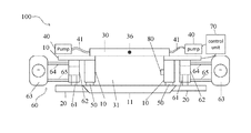
- FIG. 2 shows a schematic structural view of the proximity exposure device 100 according to an embodiment of the present disclosure.
- the proximity exposure device 100 includes a loading table 10 , a holder 20 , a vacuum hood 30 , and a pumping mechanism 40 .
- the loading table 10 is used to load the mask 11 .
- the holder 20 is mounted to the loading table 10 for holding the mask 11 .
- the holder 20 may, for example, hold the mask in a manner of vacuum suction or mechanical gripping.
- the vacuum hood 30 is provided above the mask 11 for forming a sealed space 31 above the mask 11 .
- the pumping mechanism 40 is connected to the vacuum hood 30 through a connecting pipe 41 to suck air from the vacuum hood 30 for forming a negative pressure state above the mask 11 .
- the pumping mechanism 40 may be, for example, an air pump.
- the pumping mechanism 40 may also inject air into the vacuum hood 30 .
- FIG. 3 shows a schematic view of the effect of improving the deformation of the mask by the proximity exposure device 100 according to the embodiment shown in FIG. 2 .
- air is sucked from the vacuum hood 30 by the pumping mechanism 40 , and a negative pressure state is created in the sealed space 31 above the mask 11 .
- the mask 11 may be prevented from flexing due to gravity and the mask 11 may be accurately kept in a horizontal state.
- the exposure gap P can be kept constant between the mask 11 and the substrate to be exposed 90 , and the exposure accuracy of the exposure device is prevented from being decreased due to deformation of the mask 11 .
- the vacuum hood 30 , the pumping mechanism 40 and the connecting pipe 41 are all provided outside the loading table 10 , thereby it is possible to easily upgrade the conventional proximity exposure device without a significant modification to the loading stage 10 .
- a sealing structure 50 is provided below the loading table 10 for sealing the mask 11 under the condition of vacuuming the vacuum hood 30 , and thus forming a sealed space 31 above the mask 11 .
- the sealing structure 50 may be, for example, a rubber washer made of a high purity silicone rubber to prevent the internal additives from being precipitated to form particles and thus contaminate the mask.
- the shape of the rubber washer may be designed according to the shape of the mask. For example, under the condition that the mask 11 is in a rectangular shape, the shape of the rubber washer may be a rectangular annular gasket corresponding to the shape of the periphery of the rectangular mask. The length, width and wireframe thickness of the rubber washer may be appropriately selected depending on the application.
- FIG. 4 shows a schematic view of vacuum hood 30 and the loading table 10 being connected by an exemplary mechanical connection.
- the loading table 10 is provided with a slot 12 and the bottom surface of the vacuum hood 30 is provide with a fixing rod 32 .
- the contact part between the fixing rod 32 and the slot 12 is provided with a rubber pad 33 which contributes to maintain the sealing property.
- a sealed mechanical connection may be achieved by inserting the fixing rod 32 into the slot 12 on the loading table 10 through the rubber pad 33 .
- FIG. 5 shows a schematic view of an example structure of the vacuum hood 30 in FIG. 2 .
- the vacuum hood 30 is of a substantially rectangular bottomless box-like shape as shown in FIG. 5 .
- the bottom of the rectangular box opens toward the mask.
- Air introduction holes 35 are formed in the side surfaces of the left and right ends of the vacuum hood 30 .
- the air introduction holes 35 may be connected to the pumping mechanism 40 through the connecting pipe 41 , respectively, as shown in FIG. 2 . It will be appreciated that the number, size and location of the air introduction holes 35 are not limited and may be set according to different applications.
- At least one air introduction hole 36 may be formed in the vacuum hood 30 .
- the air introduction holes 36 are provided on the front surface and the rear surface of the vacuum hood 30 . It will be understood that the number, size and installation position of the air introduction holes 36 are not limited and may be set according to different applications.
- the air introduction holes 36 function to introduce the outside air to balance the pressure in the vacuum hood 30 during the evacuation of the vacuum hood 30 , so as to prevent the negative pressure inside the vacuum hood from being excessively large, resulting in deformation of the mask in a direction opposite to gravity and then a damage to the mask.
- a regulating valve 37 may be mounted on the air introduction hole 36 and the flow rate of the outside air flowing into the vacuum hood 30 through the air introduction hole 36 may be adjusted by controlling the opening of the regulating valve 37 so as to balance the negative pressure in the vacuum hood 30 , controlling the vacuum degree within the vacuum hood 30 better.
- the high-strength glass may be used, the transmittance of which is more than 95%, and the SiO2 content of which is more than 99.5%.
- it has low thermal expansion coefficient, high temperature resistance, good chemical stability, high flatness, and may be transmissive for the ultraviolet light, may guarantee the light passing through directly, the density of which is 2.4-2.6 ⁇ 10 3 Kg/m 3 .
- the diameter of the air outlet hole 35 may be 20 mm-30 mm and the diameter of the air introduction hole 36 may be 10-15 mm.
- the regulating valve 37 of the air introduction hole 36 is operated to decrease the diameter of the air introduction hole 36 , so that the air introduction hole 36 retains an opening of 1.0-1.5 mm. Then, the air pump starts to suck air, the speed of which is maintained at 1.0-1.5 m 3 /min.
- the negative pressure detector shows the pressure within the cavity is in a range of 10 Kpa-15 Kpa, deformation of the mask may be basically disappeared. If the pressure is too large, the sucking speed may be reduced or the diameter of the regulating valve 37 may be increased.
- the proximity exposure device 100 may further include a drive mechanism 60 for driving the holder 20 to move up and down.
- the drive mechanism 60 may drive the holder 20 to move away from the loading table 10 to form a large space between the holder 20 and the loading table 10 to facilitate loading the mask 11 .
- the drive mechanism 60 may drive the holder 20 to move towards the loading table 10 so that the mask 11 contacts the sealing structure 50 below the loading table 10 and then a sealed space 31 is formed among the loading table 10 , the vacuum hood 30 and the mask 11 . In this way, the mask may be easily loaded.
- the mask 11 may be placed to the exposure position by a manipulator, and then the holder 20 is moved to the exposure position and the mask 11 is loaded onto the holder 20 ; or the mask 11 may be loaded to the holder 20 , and then the holder 20 is moved to the exposure position.
- the holder 20 may be moved up and down at a distance, for example, from 0 mm to 500 mm.
- a distance for example, from 0 mm to 500 mm.
- the drive mechanism 60 may be a hydraulic drive mechanism including a piston rod 61 , a cylinder block 62 , and an electrohydraulic servo valve 63 .
- the piston rod 61 is connected to the holder 20 to drive the holder 20 to move up and down.
- the cylinder block 62 may be fixed to the loading table 10 for receiving the piston rod 61 and the hydraulic oil.
- the electrohydraulic servo valve 63 is connected to the cylinder block 62 through the first hydraulic oil pipe 64 and the second hydraulic oil pipe 65 , and controls the piston rod 61 to move up and down by controlling the hydraulic oil to flow into and out of the cylinder block 62 through the first hydraulic oil pipe 64 and the second hydraulic oil pipe 65 .
- FIGS. 6 a and 6 b are enlarged views showing the operation of the hydraulic drive mechanism in FIG. 2 .
- FIG. 6 a shows the state in which the drive mechanism 60 drives the holder 20 to move away from the loading table 10
- FIG. 6 b shows the state in which the drive mechanism 60 drives the holder 20 to move close to the loading table 10 .
- the electro-hydraulic servo valve 63 controls the upper first hydraulic oil pipe 64 to feed the oil, and the lower second hydraulic oil pipe 65 to discharge the oil.
- the piston rod 61 in the hydraulic drive mechanism moves downward and drive the holder 20 to move down until a sufficient space is reserved above the holder 20 , so as to maintain hydraulic pressure stable and to place the mask 11 to the exposure position.
- the electro-hydraulic servo valve 63 controls the feeding and discharging directions of the oil, the upper first hydraulic oil pipe 64 discharges the oil, and the lower second hydraulic oil pipe 65 feeds the oil.
- the piston rod 62 moves upwardly, and drives the holder 20 to rise, so that the mask 11 is seated in position and fixed. At this time, the mask 11 is in close contact with the rubber washer 50 below the loading table 10 . The hydraulic system is then kept stable, and the mask 11 is held in the exposure position, and ready for exposure.
- the drive mechanism 60 is not limited to a hydraulic drive mechanism as long as it may drive the holder 20 to move up and down.
- the proximity exposure device 100 may further include a control unit 70 for controlling the pumping operation of the pumping mechanism 40 so as to control the magnitude of the negative pressure in the vacuum hood 30 .
- the control unit 70 may include, for example, a computer or other controller.
- the control unit 70 may also control the operation of the drive mechanism 60 , for example, by controlling the up and down movement of the piston rod 61 with the electro-hydraulic servo valve 63 .
- the control unit 70 may also control the opening of the regulating valve 37 to control the flow rate of the outside air flowing into the vacuum hood 30 through the air introduction hole 36 to maintain the balanced pressure in the vacuum hood 30 to prevent the mask from being deformed in a direction opposite to gravity.
- the proximity exposure device 100 may further include a negative pressure measuring device 80 for measuring the magnitude of negative pressure within the vacuum hood 30 , and sends the measurement result to the control unit 70 .
- the negative pressure measuring device 80 is for example, mounted on the inner wall of the loading table 10 in the vacuum hood 30 .
- the control unit 70 controls the pumping operation of the pumping mechanism 40 and/or adjusts the opening of the valve 37 in accordance with the measurement result of the negative pressure measuring device 80 .
- control unit 70 stores reference negative pressure values corresponding to different types of mask in advance as a target pressure, and compares the negative pressure value transmitted from the negative pressure measuring device 80 with the corresponding reference negative pressure value, and then controls the pumping operation of the pumping mechanism 40 and/or the opening of the valve 37 based on the comparison result, until the negative pressure measured by the negative pressure measuring device 80 is substantially equal to the target pressure.
- M mask is the quality of the mask
- L mask is the length of the mask
- W mask is the width of the mask
- g is the gravitational acceleration of the installation site.
- the reference negative pressure V represents the vacuum degree required to counteract gravity. It will be understood by those skilled in the art that the above formula (1) may be modified by replacing the above-mentioned standard pressure value 101325 Pa with the actual air pressure under the condition that the exposure device is not installed at a site under a standard atmospheric pressure.
- the vacuum degree may be calibrated according to different exposure devices, to test the deformation amount and the exposure effect of the specific mask under different vacuum degrees, to find reference negative pressure values suitable for different devices as the target pressure, and the present disclosure is not limited thereto.
- the mask deformation may be basically eliminated under the condition that it is achieved a suitable vacuum degree within the vacuum hood.
- FIG. 7 shows a block diagram of a control system according to an example of the proximity exposure device 100 shown in FIG. 2 .
- the control system includes a control unit 70 , a negative pressure measuring device 80 , a pumping mechanism 40 , a regulating valve 37 and a drive mechanism 60 .
- the control unit 70 receives the negative pressure measurement result from the negative pressure measuring device 80 and controls the operation of the pumping mechanism 40 and/or the regulating valve 37 in accordance with the negative pressure measurement result. Further, the control unit 70 also controls the drive mechanism 60 to drive the holder 20 to move up and down in accordance with the user input command to load and unload the mask 11 .
- the control unit 70 may be connected to the negative pressure measuring device 80 , the pumping mechanism 40 , the regulating valve 37 and the drive mechanism 60 in a wired manner, and may be communicated to the negative pressure measuring device 80 , the pumping mechanism 40 , the regulating valve 37 and the drive mechanism 60 in a wireless manner to achieve control.
- FIG. 8 shows a flow chart of the exposure process of the proximity exposure device as shown in FIG. 2 .
- FIG. 8 a shows a flow chart of the process of loading a mask; and
- FIG. 8 b shows a flow chart of the process of unloading a mask.
- the exposure process includes: firstly loading the mask 11 onto the holder 20 to make the mask 11 be opposite to the substrate to be exposed (S 1 ).
- a sealed space 31 is formed among the loading table 10 , the vacuum hood 30 and the mask 11 .
- a step of sucking the air in the vacuum hood 30 by the pumping mechanism 40 to form a negative pressure state (S 2 ) above the mask 11 is performed.
- a step of irradiating the exposure light onto the substrate to be exposed through the mask 11 to expose the substrate (S 3 ) is performed.
- the negative pressure state of the vacuum hood 30 is maintained.
- the negative pressure state is formed in the vacuum hood 30 by the pumping mechanism 40 , the action of the gravity on the mask 11 is canceled, preventing the mask 11 from flexing due to the gravitational force, so that the mask 11 is always kept in a horizontal state. It allows the gap between the mask and the substrate to be exposed to remain constant, thus ensuring the exposure accuracy of the exposure device.
- loading the mask 11 onto the holder 20 comprises firstly driving the holder 20 to move away from the loading table 10 , for example move downwards at a distance of 200-220 mm, under action of the hydraulic drive mechanism 60 , to leave a space required for loading a mask over the holder 20 (S 11 ). Then, a step of loading the mask 11 onto the holder 20 through the space (S 12 ) is performed.
- the mask 11 may be firstly placed at the exposure position for being exposed, for example, the mask may be conveyed to the exposure position by a manipulator, and then the holder 20 is moved toward the loading table 10 to the exposure position and the mask 11 is loaded for being exposed; or the mask 11 may be loaded onto the holder 20 firstly, and then the holder 20 is moved toward the loading table 10 to the exposure position for being exposed.
- the inconvenience of loading a mask 11 because the vacuum hood 30 is mounted on the loading table 10 can be prevented.
- unloading the mask 11 from the holder 20 after the exposure is finished includes: firstly gradually removing the negative pressure state of the vacuum hood 30 .
- the suction rate of the pumping mechanism 40 is reduced until the pumping mechanism 40 is closed.
- the opening of the regulating valve 37 of the air introduction hole 36 is increased, and the outside air is introduced into the vacuum hood 30 to de-vacuum the vacuum hood (S 41 ).
- the holder 20 is moved away from the loading table 10 .
- the holder 20 is moved downward at a distance of 200-220 mm by the drive mechanism 40 to leave a sufficient space to unload the mask 11 over the holder (S 42 ).
- a step of unloading the mask from the holder 20 through this space (S 43 ) is performed.
- the mask 11 is removed from the holder 20 by a manipulator.
- the inconvenience of unloading a mask 11 because the vacuum hood 30 is mounted on the loading table 10 can be prevented.
- the magnitude of the negative pressure in the vacuum hood 30 may be measured, and the pumping operation of the pumping mechanism 40 or the opening of the regulating valve 37 may be controlled by the control unit 70 in accordance with the measurement result so as to maintain a constant negative pressure within the vacuum hood 30 .
- the influence of the gravity on the mask is eliminated by vacuum pumping method with a vacuum hood above the loading table.
- an air introduction hole and an air outlet hole are formed on the vacuum hood.
- the vacuum hood is evacuated through the air outlet hole, and the outside air is appropriately introduced through the air introduction hole, thereby maintaining the balance of the vacuum degree in the vacuum hoop. This may remove the impact of gravity, while preventing the negative pressure being too large in the vacuum hood to ensure that the mask does not deform, so as to maintain uniform exposure gap to ensure the exposure accuracy of the exposure device. It may also effectively reduce the risk of the mask being scratched during the low gap exposure.
- the holder drive mechanism improves the operation of the holder drive mechanism, the holder is moved downwardly during loading and unloading of the mask, a sufficient space is reserved above the holder for loading and unloading the mask so that the process of loading and unloading the mask is much easier.
- the proximity exposure device of the embodiment of the present disclosure is able to precisely control the magnitude of the negative pressure in the vacuum hood, effectively solving the problem of the deformation of the mask due to gravity, and it is not necessary to manufacture corresponding masks according to different exposure devices, reducing the cost for manufacturing the masks.
- the vacuum hood, the pumping mechanism and the connecting pipe are provided outside the loading table, and it is possible to easily upgrade the existing exposure device without a substantial modification to the loading table.
Landscapes
- Physics & Mathematics (AREA)
- General Physics & Mathematics (AREA)
- Engineering & Computer Science (AREA)
- Computer Networks & Wireless Communication (AREA)
- Health & Medical Sciences (AREA)
- Environmental & Geological Engineering (AREA)
- Epidemiology (AREA)
- Public Health (AREA)
- Exposure And Positioning Against Photoresist Photosensitive Materials (AREA)
Abstract
Description
V=101325 Pa−(M mask ×g)/L mask ×W mask. . . (1)
Claims (12)
Applications Claiming Priority (3)
| Application Number | Priority Date | Filing Date | Title |
|---|---|---|---|
| CN201710187193 | 2017-03-23 | ||
| CN201710187193.X | 2017-03-23 | ||
| CN201710187193.XA CN106773557B (en) | 2017-03-23 | 2017-03-23 | Proximity exposure device and exposure method thereof |
Publications (2)
| Publication Number | Publication Date |
|---|---|
| US20180275522A1 US20180275522A1 (en) | 2018-09-27 |
| US10209632B2 true US10209632B2 (en) | 2019-02-19 |
Family
ID=58967382
Family Applications (1)
| Application Number | Title | Priority Date | Filing Date |
|---|---|---|---|
| US15/789,764 Active US10209632B2 (en) | 2017-03-23 | 2017-10-20 | Proximity exposure device and exposure method thereof |
Country Status (2)
| Country | Link |
|---|---|
| US (1) | US10209632B2 (en) |
| CN (1) | CN106773557B (en) |
Families Citing this family (6)
| Publication number | Priority date | Publication date | Assignee | Title |
|---|---|---|---|---|
| CN107844034B (en) * | 2017-11-20 | 2019-11-12 | 张家港奇点光电科技有限公司 | A New Exposure Platform of Exposure Machine |
| CN109581828A (en) * | 2019-01-23 | 2019-04-05 | 深圳市华星光电技术有限公司 | Exposure device and exposure method |
| CN113741151A (en) * | 2020-05-29 | 2021-12-03 | 上海微电子装备(集团)股份有限公司 | Mask plate shaping device, mask plate shaping method and photoetching machine |
| CN115704999B (en) * | 2021-08-12 | 2025-12-02 | 吉林华微电子股份有限公司 | A type of copy machine |
| CN114609872B (en) * | 2022-03-16 | 2022-12-13 | 东莞市友辉光电科技有限公司 | Light shield bending-resistant method and large-size parallel light exposure machine |
| CN115772653B (en) * | 2022-11-24 | 2025-03-28 | 常州瑞择微电子科技有限公司 | HMDS processing mechanism and processing technology |
Citations (7)
| Publication number | Priority date | Publication date | Assignee | Title |
|---|---|---|---|---|
| JPH04165354A (en) | 1990-10-30 | 1992-06-11 | Topcon Corp | Mask capable of being compensated in its deflection |
| JPH0882919A (en) | 1994-09-12 | 1996-03-26 | Hitachi Ltd | Photomask and exposure apparatus using the same |
| JP2006093604A (en) | 2004-09-27 | 2006-04-06 | Nsk Ltd | Proximity exposure equipment |
| JP2009277900A (en) | 2008-05-15 | 2009-11-26 | V Technology Co Ltd | Exposure device and photomask |
| CN102955373A (en) | 2011-08-10 | 2013-03-06 | 恩斯克科技有限公司 | Approaching exposure apparatus and approaching type exposure method |
| CN104020643A (en) | 2013-03-01 | 2014-09-03 | 上海微电子装备有限公司 | Large mask plate face type compensation device for photoetching equipment |
| CN104635427A (en) | 2013-11-14 | 2015-05-20 | 上海微电子装备有限公司 | Mask shaping apparatus used for lithography equipment and mask shaping method |
-
2017
- 2017-03-23 CN CN201710187193.XA patent/CN106773557B/en active Active
- 2017-10-20 US US15/789,764 patent/US10209632B2/en active Active
Patent Citations (7)
| Publication number | Priority date | Publication date | Assignee | Title |
|---|---|---|---|---|
| JPH04165354A (en) | 1990-10-30 | 1992-06-11 | Topcon Corp | Mask capable of being compensated in its deflection |
| JPH0882919A (en) | 1994-09-12 | 1996-03-26 | Hitachi Ltd | Photomask and exposure apparatus using the same |
| JP2006093604A (en) | 2004-09-27 | 2006-04-06 | Nsk Ltd | Proximity exposure equipment |
| JP2009277900A (en) | 2008-05-15 | 2009-11-26 | V Technology Co Ltd | Exposure device and photomask |
| CN102955373A (en) | 2011-08-10 | 2013-03-06 | 恩斯克科技有限公司 | Approaching exposure apparatus and approaching type exposure method |
| CN104020643A (en) | 2013-03-01 | 2014-09-03 | 上海微电子装备有限公司 | Large mask plate face type compensation device for photoetching equipment |
| CN104635427A (en) | 2013-11-14 | 2015-05-20 | 上海微电子装备有限公司 | Mask shaping apparatus used for lithography equipment and mask shaping method |
Non-Patent Citations (2)
| Title |
|---|
| First Chinese Office Action, for Chinese Patent Application No. 201710187193.X, dated Dec. 5, 2017, 14 pages. |
| Second Chinese Office Action, for Chinese Patent Application No. 201710187193.X, dated Aug. 1, 2018. |
Also Published As
| Publication number | Publication date |
|---|---|
| CN106773557A (en) | 2017-05-31 |
| CN106773557B (en) | 2019-08-30 |
| US20180275522A1 (en) | 2018-09-27 |
Similar Documents
| Publication | Publication Date | Title |
|---|---|---|
| US10209632B2 (en) | Proximity exposure device and exposure method thereof | |
| US20100133735A1 (en) | Substrate holding apparatus, substrate holding method, exposure apparatus, and device manufacturing method | |
| JP6400120B2 (en) | Substrate holding device, lithographic apparatus, and article manufacturing method | |
| CN1326229C (en) | Load-lock technique | |
| US20150059644A1 (en) | Coating film forming apparatus | |
| US9740109B2 (en) | Holding device, lithography apparatus, and method for manufacturing item | |
| CN101794077A (en) | Workbench and method for automatically installing gasket | |
| JP5884267B2 (en) | Object transport apparatus, exposure apparatus, device manufacturing method, flat panel display manufacturing method, and object transport method | |
| KR20160115693A (en) | Heating and drying device | |
| JP2016054232A (en) | Imprint device | |
| KR20140041819A (en) | Contact exposure device and contact exposure method | |
| JP2010054933A (en) | Exposure apparatus | |
| JP7142518B2 (en) | Substrate transport apparatus, lithographic apparatus, and article manufacturing method | |
| JP2015222778A (en) | Holding device lithographic apparatus, and method of manufacturing article | |
| JP2014071206A (en) | Proximity exposure apparatus | |
| JP2010040831A (en) | Exposing method for substrate in exposing device | |
| KR102926341B1 (en) | Stage apparatus, lithography apparatus and article manufacturing method | |
| US12228855B2 (en) | Imprint apparatus, imprint method, article manufacturing method, and storage medium | |
| JP2014035399A (en) | Object exchange method, object exchange system, exposure equipment, production method of flat panel display, and device production method | |
| JP2022120603A (en) | Exposure device | |
| JP2018207026A (en) | Holding device, control method therefor, lithographic apparatus, and article manufacturing method | |
| JP2010093143A (en) | Operation valve, aligner, and method for manufacturing device | |
| CN101794067B (en) | Workbench, high-speed vacuum workbench system, and high-speed vacuum forming method | |
| GB2271430A (en) | Method for alignment employing film mask and aligner therefor | |
| KR20210033094A (en) | Bonding device for display |
Legal Events
| Date | Code | Title | Description |
|---|---|---|---|
| AS | Assignment |
Owner name: HEFEI BOE OPTOELECTRONICS TECHNOLOGY CO., LTD., CH Free format text: ASSIGNMENT OF ASSIGNORS INTEREST;ASSIGNORS:JIANG, SHENGCHAO;YU, SHIRONG;MENG, QINGYONG;REEL/FRAME:043917/0183 Effective date: 20170920 Owner name: BOE TECHNOLOGY GROUP CO., LTD., CHINA Free format text: ASSIGNMENT OF ASSIGNORS INTEREST;ASSIGNORS:JIANG, SHENGCHAO;YU, SHIRONG;MENG, QINGYONG;REEL/FRAME:043917/0183 Effective date: 20170920 |
|
| FEPP | Fee payment procedure |
Free format text: ENTITY STATUS SET TO UNDISCOUNTED (ORIGINAL EVENT CODE: BIG.); ENTITY STATUS OF PATENT OWNER: LARGE ENTITY |
|
| STCF | Information on status: patent grant |
Free format text: PATENTED CASE |
|
| MAFP | Maintenance fee payment |
Free format text: PAYMENT OF MAINTENANCE FEE, 4TH YEAR, LARGE ENTITY (ORIGINAL EVENT CODE: M1551); ENTITY STATUS OF PATENT OWNER: LARGE ENTITY Year of fee payment: 4 |