US10209292B2 - Partial discharge determination method, partial discharge determination apparatus, and partial discharge determination system for power device, and method for manufacturing power device including the partial discharge determination method - Google Patents
Partial discharge determination method, partial discharge determination apparatus, and partial discharge determination system for power device, and method for manufacturing power device including the partial discharge determination method Download PDFInfo
- Publication number
- US10209292B2 US10209292B2 US15/520,257 US201515520257A US10209292B2 US 10209292 B2 US10209292 B2 US 10209292B2 US 201515520257 A US201515520257 A US 201515520257A US 10209292 B2 US10209292 B2 US 10209292B2
- Authority
- US
- United States
- Prior art keywords
- partial discharge
- acoustic signal
- voltage
- mechanical oscillation
- acoustic
- Prior art date
- Legal status (The legal status is an assumption and is not a legal conclusion. Google has not performed a legal analysis and makes no representation as to the accuracy of the status listed.)
- Active, expires
Links
Images


Classifications
-
- G—PHYSICS
- G01—MEASURING; TESTING
- G01R—MEASURING ELECTRIC VARIABLES; MEASURING MAGNETIC VARIABLES
- G01R31/00—Arrangements for testing electric properties; Arrangements for locating electric faults; Arrangements for electrical testing characterised by what is being tested not provided for elsewhere
- G01R31/12—Testing dielectric strength or breakdown voltage ; Testing or monitoring effectiveness or level of insulation, e.g. of a cable or of an apparatus, for example using partial discharge measurements; Electrostatic testing
- G01R31/1209—Testing dielectric strength or breakdown voltage ; Testing or monitoring effectiveness or level of insulation, e.g. of a cable or of an apparatus, for example using partial discharge measurements; Electrostatic testing using acoustic measurements
-
- G—PHYSICS
- G01—MEASURING; TESTING
- G01H—MEASUREMENT OF MECHANICAL VIBRATIONS OR ULTRASONIC, SONIC OR INFRASONIC WAVES
- G01H3/00—Measuring characteristics of vibrations by using a detector in a fluid
- G01H3/04—Frequency
- G01H3/08—Analysing frequencies present in complex vibrations, e.g. comparing harmonics present
-
- G—PHYSICS
- G01—MEASURING; TESTING
- G01R—MEASURING ELECTRIC VARIABLES; MEASURING MAGNETIC VARIABLES
- G01R31/00—Arrangements for testing electric properties; Arrangements for locating electric faults; Arrangements for electrical testing characterised by what is being tested not provided for elsewhere
- G01R31/12—Testing dielectric strength or breakdown voltage ; Testing or monitoring effectiveness or level of insulation, e.g. of a cable or of an apparatus, for example using partial discharge measurements; Electrostatic testing
-
- G—PHYSICS
- G01—MEASURING; TESTING
- G01R—MEASURING ELECTRIC VARIABLES; MEASURING MAGNETIC VARIABLES
- G01R31/00—Arrangements for testing electric properties; Arrangements for locating electric faults; Arrangements for electrical testing characterised by what is being tested not provided for elsewhere
- G01R31/40—Testing power supplies
Definitions
- the present invention relates to a partial discharge determination method, a partial discharge determination apparatus, and a partial discharge determination system for a power device, as well as a power device for which whether partial discharge is caused is determined by the method, apparatus, and system, and a method for manufacturing a power device including the partial discharge determination method.
- Partial discharge is a precursory phenomenon of dielectric breakdown (complete electrical breakdown) of the device. Dielectric breakdown of the device can be prevented by establishing a technique for reliably detecting partial discharge.
- a high-voltage-charged unit of the electrical device is not exposed but housed in a casing of an insulating material or a metal case (tank) at a ground potential.
- Japanese Patent Laying-Open No. 2008-180681 discloses a technique for simultaneously detecting, by the acoustic emission sensor, an elastic wave signal generated due to partial discharge and detecting, by a current sensor, a current flowing along the tank's wall surface or a grounding conductor due to partial discharge.
- This technique makes use of a difference in space propagation velocity between an acoustic signal and an electrical signal. Namely, when a partial discharge signal is generated in an electrical device, a current pulse due to the partial discharge is initially detected by the current sensor.
- the partial discharge signal is detected by the acoustic emission sensor.
- one method for estimating the partial-discharge charge amount namely the amount of electric charge released due to partial discharge which occurs in a power device in operation is a method using the maximum amplitude of a partial discharge signal waveform detected by the acoustic emission sensor.
- PTD 2 Japanese Patent Laying-Open No. 9-152424 discloses that a correlation between the maximum amplitude detected by the acoustic emission sensor and the partial-discharge charge amount is determined in advance, and this correlation is used to determine the magnitude of the discharge which occurs in the power device.
- PTD 1 and PTD 2 are directed to a preventive maintenance diagnosis technique for preventing dielectric breakdown due to degradation with time of an electrical device after installed in a field, and basically applied to normal operation of the electrical device to which commercial AC power is applied.
- a lighting impulse withstand voltage test is conducted as an insulation test before product shipment or a test for product development.
- a standard specification standard specification JEC0103 (2005) defined by the Japanese Electrotechnical Committee, for example
- an electrical device is regarded as passing the test, if dielectric breakdown does not occur in the device when an impulse waveform having a prescribed voltage waveform is applied.
- the scheme of PTD 1 cannot detect partial discharge in a lighting impulse withstand voltage test.
- the scheme of PTD 2 cannot acquire, by the acoustic emission sensor, the partial discharge signal in the lighting impulse withstand voltage test and therefore cannot estimate the partial-discharge charge amount.
- the present invention has been made to solve the problems as described above, and an object of the invention is to provide a partial discharge determination method, a partial discharge determination apparatus, and a partial discharge determination system for determining whether or not partial discharge is caused, by which partial discharge can be detected and further how much margin is left before dielectric breakdown can be indicated in a lighting impulse withstand voltage test, and to provide a power device for which whether or not partial discharge is caused is determined, and a method for manufacturing a power device including the partial discharge determination method.
- the present invention is directed to a partial discharge determination method using an acoustic emission sensor.
- the method includes: applying an impulse voltage to a device under test; acquiring an acoustic signal resulting from application of the impulse voltage, by the acoustic emission sensor installed on a wall surface of a casing which houses the device under test; removing, through a low-pass filter, an electromagnetic noise superimposed on the acoustic signal detected by the acoustic emission sensor; removing a mechanical oscillation component of the device under test, from the acoustic signal resulting from application of the impulse voltage which is a high voltage, based on the mechanical oscillation component acquired in advance and included in the acoustic signal resulting from application of the impulse voltage which is a low voltage causing no partial discharge; determining whether partial discharge is caused in the device under test, based on the acoustic signal resulting from application of the high voltage, the mechanical oscillation component being removed from the acoustic signal; and determining, when the partial discharge is
- the electromagnetic noise superimposed on the acoustic signal and the mechanical oscillation component of the device under test are removed to thereby enable accurate determination as to whether or not partial discharge is caused in the device under test. Further, based on the measurement signal taken by the acoustic emission sensor and the feature amount of the partial discharge signal which are acquired in advance, how much margin is left before dielectric breakdown of the device under test can be recognized.
- FIG. 1 is a perspective view showing a configuration of a shell-type power transformer as an example of the device to be tested for partial discharge in accordance with a first embodiment of the present invention.
- FIG. 2 is a perspective cross-sectional view showing a coil structure of a shell-type power transformer as a typical example of the device to be tested in accordance with the first embodiment of the present invention.
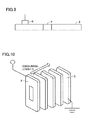
- FIG. 3 is a diagram showing a configuration of a partial discharge determination apparatus in accordance with the first embodiment.
- FIG. 4 is a diagram showing a relation between the square of the peak value of an impulse voltage and the amplitude value of a mechanical oscillation component.
- FIG. 5 is a diagram showing a configuration of a partial discharge determination system in accordance with the first embodiment of the present invention.
- FIG. 6 is a flowchart showing a procedure of a partial discharge determination method in accordance with the first embodiment of the present invention.
- FIG. 7 is a diagram for illustrating waveforms obtained by the partial discharge determination method.
- FIG. 8 is a diagram for illustrating waveforms obtained by the partial discharge determination method.
- FIG. 9 is a diagram for illustrating a scheme for acquiring a correlation between a feature amount of a partial discharge signal and a discharge length.
- FIG. 10 is a diagram for illustrating the discharge length.
- FIG. 11 is a diagram showing a relation between the discharge length and the amplitude of a first arrival wave of a partial discharge signal acquired by an acoustic emission sensor.
- FIG. 12 is a diagram showing a relation between the discharge length and the duration of a partial discharge signal acquired by an acoustic emission sensor.
- FIG. 13 is a flowchart showing a procedure of a partial discharge determination method in accordance with a fourth embodiment of the present invention.
- a shell-type power transformer is used as an example of the electrical device which is a device to be tested.
- a device to be tested by the partial discharge determination method and the partial discharge determination apparatus in accordance with the present invention may be any electrical device such as power transforming device or power distribution board.
- the device to be tested may be core-type transformer, insulating switching device, or the like.
- a lighting impulse withstand voltage test is conducted as one of insulation tests which are performed before product shipment. This test is conducted for ensuring electrical insulation performance even when an abnormal voltage waveform is applied during normal operation of an electrical device such as power transformer.
- the abnormal voltage waveform is for example lighting surge or switching surge which is generated outside the electrical device.
- the test is conducted for ensuring that dielectric breakdown will not occur even when a voltage waveform defined by the standard specification is applied to an electrical device. It should be noted that, in order to ensure the insulation reliability of a product, it is necessary to clarify a margin before dielectric breakdown due to an applied voltage.
- an electromagnetic wave method for detecting for detecting, by means of an electromagnetic sensor (antenna)
- an electromagnetic wave which is generated due to partial discharge or a method for detecting a current pulse which flows due to occurrence of partial discharge
- a partial discharge signal in the impulse withstand voltage test is buried in the electromagnetic noise of the impulse voltage generator, which makes it impossible to detect occurrence of the partial discharge.
- a method for detecting partial discharge of a power device As another method for detecting partial discharge of a power device, a method is also generally performed which detects, by an acoustic emission sensor, an elastic wave signal generated due to partial discharge and propagated in the device.
- the applicant has made it clear that use of this method for the lighting impulse withstand voltage test is accompanied by the following problems.
- an impulse withstand voltage test for a power transformer In an impulse withstand voltage test for a power transformer, application of an impulse voltage to the transformer causes a charging current to momentarily flow through a capacitance of the transformer. As the charging current flows through coils, a physical force is generated between windings and the coil mechanically oscillates. The mechanical oscillation of the coil causes an elastic wave to be propagated to an insulating oil contained in a transformer tank. Therefore, when it is attempted to detect partial discharge by means of an acoustic emission sensor, the mechanical oscillation component is detected regardless of whether or not partial discharge occurs in the tank.
- a margin is used as an indicator of a tolerance before dielectric breakdown in an impulse withstand voltage test.
- FIG. 1 is a perspective view showing a configuration of a shell-type power transformer 50 as an example of the device to be tested for partial discharge in accordance with the first embodiment of the present invention.
- the components are each partially cut away.
- shell-type power transformer 50 includes a core 1 , a coil portion 2 formed of windings around core 1 , a tank 3 housing core 1 and coil portion 2 , and an insulating oil (not shown) which is contained in tank 3 and in which core 1 and coil portion 2 are immersed.
- Core 1 is made up of multiple laminated magnetic steel sheets.
- two rectangular parallelepiped cores 1 each having an opening in the central portion are arranged next to each other.
- Coil portion 2 is wound around respective legs, adjacent to each other, of two cores 1 , and runs through each of respective openings of these cores 1 .
- the insulating oil serves as both an electrically insulating medium and a cooling medium.
- the insulating oil flows around cores 1 and coil portion 2 .
- mineral oil is used as the insulating oil.
- ester oil may be used as the insulting oil.
- FIG. 2 is a perspective cross-sectional view showing a coil structure of shell-type power transformer 50 as a typical example of the device to be tested in accordance with the first embodiment of the present invention.
- coil portion 2 is made up of a plurality of coils arranged side by side, from a high-voltage-side coil 4 at the highest voltage which is connected to an impulse voltage generator and to which a high-voltage impulse waveform is applied, to a ground coil 5 at the lowest voltage.
- the lowest-voltage ground coil 5 has an end P2 which is grounded.
- a highest electric field is formed around high-voltage-side coil 4 to which the voltage is applied, and the region around coil 4 becomes a site of occurrence of partial discharge.
- shell-type power transformer 50 is designed to suppress development of partial discharge even when the partial discharge is caused and developed, by appropriately disposing an insulating barrier.
- the partial discharge determination method determines, by means of an acoustic emission sensor, whether or not partial discharge occurs when an impulse voltage is applied. At this time, the method avoids a partial discharge signal from being buried in the aforementioned electromagnetic noise. Further, the method makes use of a mechanical oscillation component waveform which is generated upon application of a low voltage which does not certainly cause partial discharge, so as to remove a mechanical oscillation component when a high voltage is applied which may cause partial discharge. In this way, the method extracts only a partial discharge signal.
- the partial discharge determination method for an electrical device in accordance with the present embodiment determines a margin before dielectric breakdown of the electrical device, from a feature amount of a partial discharge signal of the acoustic emission sensor and a feature amount of partial discharge which are acquired in advance.
- FIG. 3 is a diagram showing a configuration of a partial discharge determination apparatus in accordance with the first embodiment.
- a partial discharge determination apparatus 8 includes a low-pass filter 13 , an applied-voltage capture unit 9 , a waveform record device 10 , a mechanical oscillation removal unit 15 , a partial discharge determination unit 11 , a feature amount identification unit 18 , a margin determination unit 12 , a correlation value storage unit 19 , and an output unit 20 .
- Impulse voltage generator 14 applies, to shell-type power transformer 50 , an impulse voltage waveform which meets the specification.
- the wave front duration (rise time) and the wave tail duration (fall time) of the voltage waveform are defined by the specification and the peak value of the voltage waveform is defined by the specification depending on the rated voltage and/or the capacitance of the high-voltage device.
- Applied-voltage capture unit 9 captures the impulse voltage waveform to store it in waveform record device 10 , and identifies the voltage application start time from the captured impulse voltage waveform to store it in waveform record device 10 . Since the voltage waveform which is output from impulse voltage generator 14 is of a high voltage, applied-voltage capture unit 9 may store, in waveform record device 10 , the voltage waveform obtained through voltage division of the captured impulse voltage waveform by a voltage divider.
- Acoustic emission sensor 6 is installed on the external surface of tank 3 of shell-type power transformer 50 which is a device to be tested. Acoustic emission sensor 6 acquires an acoustic signal resulting from application of the impulse voltage and generated in tank 3 . Acoustic emission sensor 6 detects, in accordance with the AE (Acoustic Emission) method, an elastic wave (stress wave) which is caused by a mechanical motion of a substance, and outputs the result of the detection in the form of an electrical signal.
- AE Acoustic Emission
- impulse voltage generator 14 generates spark discharge in a sphere gap provided in generator 14 to thereby output the voltage waveform.
- Very large electromagnetic noise due to the spark discharge in the sphere gap is a factor which makes it difficult to detect the partial discharge signal.
- the duration in which the electromagnetic noise is mainly generated is at most on the order of several tens of microseconds.
- the propagation velocity of the acoustic signal in the insulating oil is generally 1400 meters per second. It takes about several hundreds of microseconds to several milliseconds for the acoustic signal generated from the device under test housed in tank 3 to reach acoustic emission sensor 6 , which, however, depends on the size of tank 3 .
- the time range in which the acoustic signal resulting from the application of the impulse voltage is detected by acoustic emission sensor 6 is after decay of most of the electromagnetic noise generated from impulse voltage generator 14 .
- the measurement signal of acoustic emission sensor 6 still has its waveform on which the electromagnetic noise component is superimposed.
- low-pass filter 13 is used.
- Low-pass filter 13 removes the electromagnetic noise component (the noise component due to impulse voltage generator 14 ) from the acquired measurement signal of acoustic emission sensor 6 .
- the function of low-pass filter 13 may be implemented by digital signal processing.
- a low-pass filter having a cutoff frequency characteristic that enables the inherent acoustic signal to be separated from the electromagnetic noise in terms of frequency is selected.
- the component on the order of several hundreds of MHz is strong.
- the acoustic signal is several tens of kHz to several hundreds of kHz.
- low-pass filter 13 having a cutoff frequency of about 1 MHz can be used to remove the electromagnetic noise component superimposed on the measurement signal of acoustic emission sensor 6 , and pass only the acoustic signal component to be detected.
- the electromagnetic noise is removed by low-pass filter 13 , the main component of the acoustic signal generated due to the application of the impulse voltage can be acquired.
- the signal having passed low-pass filter 13 contains a noise component due to mechanical oscillation of coil portion 2 in shell-type power transformer 50 that is caused by momentary flow of charging current, regardless of whether or not partial discharge occurs in shell-type power transformer 50 . This is addressed by mechanical oscillation removal unit 15 .
- Mechanical oscillation removal unit 15 removes the noise component which is generated due to mechanical oscillation and contained in the signal processed by low-pass filter 13 .
- a test voltage defined by the specification is not immediately applied. Rather, a low voltage waveform which will not certainly cause partial discharge in tank 3 of shell-type power transformer 50 is output several times to confirm whether or not the wave having the wave front duration and the wave tail duration which meet the specification is output.
- the mechanical oscillation component has a characteristic that the period of the mechanical oscillation component remains totally the same even when the peak value of the impulse voltage applied to the device under test is varied, but only the amplitude of the mechanical oscillation component is varied.
- FIG. 4 is a diagram showing a relation between the square of the peak value of an impulse voltage and the amplitude value of a mechanical oscillation component.
- the inventors of the present application have experimentally revealed, as shown in FIG. 4 , that the amplitude value of the mechanical oscillation component is proportional to the square of the charging current flowing through coil portion 2 of each winding, namely proportional to the square of the peak value of the impulse voltage.
- V1 is the peak value of the impulse voltage when the low-voltage waveform which will not cause partial discharge is applied
- A1 is the amplitude value of the mechanical oscillation component
- V2 is the peak value of the impulse voltage when the high voltage is applied in accordance with the specification of the withstand voltage test
- A2 is the amplitude value of the mechanical oscillation component
- K is the factor of proportionality.
- Waveform record device 10 records acoustic signal waveform LW which is output from low-pass filter 13 when the low voltage which will not cause partial discharge is applied, and acoustic signal waveform HW which is output from low-pass filter 13 when the high voltage is applied in accordance with the specification of the withstand voltage test.
- acoustic signal waveform LW is the waveform of the mechanical oscillation component included in the signal detected by acoustic emission sensor 6 .
- Acoustic signal waveform LW thus has amplitude value A1 of the mechanical oscillation component.
- Mechanical oscillation removal unit 15 identifies amplitude value A1 of the mechanical oscillation component, from acoustic signal waveform LW which is generated when the low voltage is applied and stored in waveform record device 10 .
- the mechanical oscillation removal unit calculates factor of proportionality K in accordance with the expression (1).
- Mechanical oscillation removal unit 15 multiplies by K the acoustic signal waveform LW which is generated when the low voltage is applied, to thereby determine mechanical oscillation component waveform NW which is generated when the high voltage is applied.
- Mechanical oscillation removal unit 15 subtracts mechanical oscillation component waveform NW which is generated when the high voltage is applied, from acoustic signal waveform HW which is generated when the high voltage is applied and stored in waveform record device 10 . In this way, the acoustic signal waveform from which the mechanical oscillation component, which is generated when the high voltage is applied, has been removed is obtained.
- the electromagnetic noise due to impulse voltage generator 14 and the mechanical oscillation component of coil portion 2 can be removed from the acoustic signal waveform detected by acoustic emission sensor 6 .
- external noise other than the aforementioned partial discharge signal may be superimposed on the acoustic signal component measured by means of acoustic emission sensor 6 .
- an impact sound generated upon impact of a foreign matter against tank 3 during the impulse voltage test or an elastic wave due to a sound generated outside tank 3 is detected as external noise by acoustic emission sensor 6 which is installed on the wall surface of tank 3 .
- It is partial discharge determination unit 11 that serves as means for removing the external noise to detect partial discharge.
- the propagation velocity of an acoustic signal in an insulating oil is generally 1400 meters per second. Based on this acoustic signal propagation velocity V and the distance, which is known in advance, between acoustic emission sensor 6 and the high-voltage-charged unit (namely high-voltage-side coil 4 ) in a structure of shell-type power transformer 50 , the time difference between the time when application of the impulse voltage is started and the time when the partial discharge signal reaches acoustic emission sensor 6 can be predicted to fall within a certain range.
- partial discharge determination unit 11 calculates time t1 by dividing, by acoustic signal propagation velocity V in the oil, the shortest distance between the location where acoustic emission sensor 6 is installed and the location where the high-voltage-charged unit in the structure of shell-type power transformer 50 is installed.
- Partial discharge determination unit 11 calculates time t2 by dividing, by acoustic signal propagation velocity V in the oil, the longest distance between the location where acoustic emission sensor 6 is installed and the location where the high-voltage-charged unit which is in the structure of shell-type power transformer 50 is located.
- Partial discharge determination unit 11 determines that partial discharge is caused in shell-type power transformer 50 , when the acoustic signal component is detected within the range of time from t1 to t2 with respect to the time when application of the impulse voltage is started. Partial discharge determination unit 11 determines that partial discharge is not caused in shell-type power transformer 50 when the acoustic signal component is not detected within the range of time from t1 to t2 with respect to the time when application of the impulse voltage is started.
- an electromagnetic wave sensor signal or a current sensor signal may be used.
- Margin determination unit 12 determines the margin before dielectric breakdown of shell-type power transformer 50 , using a correlation, which is acquired in advance before the impulse withstand voltage test, between the partial discharge signal waveform obtained by the acoustic emission sensor and a feature amount of the partial discharge.
- Output unit 20 indicates the determined margin before the dielectric breakdown.
- FIG. 5 is a diagram showing a configuration of a partial discharge determination system 40 in accordance with the first embodiment of the present invention.
- Partial discharge determination system 40 includes aforementioned impulse voltage generator 14 , acoustic emission sensor 6 , and partial discharge determination apparatus 8 .
- partial discharge determination apparatus 8 is expressed as a hardware configuration.
- Applied-voltage capture unit 9 , partial discharge determination unit 11 , margin determination unit 12 , mechanical oscillation removal unit 15 , and feature amount identification unit 18 in FIG. 3 are implemented by a processor 31 which executes a program stored in a memory 32 .
- Output unit 20 in FIG. 3 is configured as a display 33 .
- Correlation value storage unit 19 and waveform record device 10 in FIG. 3 are configured as memory 32 .
- FIG. 6 is a flowchart showing a procedure of a partial discharge determination method in accordance with the first embodiment of the present invention.
- FIGS. 7 and 8 show examples of waveforms which can be acquired in accordance with the flowchart of FIG. 6 .
- the partial discharge determination method in accordance with the present embodiment will be described below in order of the steps.
- impulse voltage generator 14 applies to shell-type power transformer 50 an impulse voltage waveform of a low voltage meeting the specification.
- FIG. 7 ( a ) shows an example of the impulse voltage waveform of the low voltage.
- V1 is the peak value of the impulse voltage waveform of the low voltage.
- step S 102 an acoustic signal resulting from application of the impulse voltage is acquired by acoustic emission sensor 6 installed on the wall surface of tank 3 .
- FIG. 7 ( b ) shows an example of the waveform of the acoustic signal acquired by acoustic emission sensor 6 (acoustic emission sensor-measured waveform).
- step S 103 the acquired measurement signal of acoustic emission sensor 6 is passed through low-pass filter 13 , and accordingly an electromagnetic noise component (noise component due to impulse voltage generator 14 ) is removed from the measurement signal of acoustic emission sensor 6 .
- Acoustic signal waveform LW which is generated when the low voltage is applied and which is output from low-pass filter 13 is stored in waveform record device 10 .
- FIG. 7 ( c ) shows an example of acoustic signal waveform LW which is generated when the low voltage is applied and which is output from low-pass filter 13 .
- A1 is the amplitude of acoustic signal waveform LW.
- step S 104 impulse voltage generator 14 applies, to shell-type power transformer 50 , an impulse voltage waveform of a high voltage meeting the specification.
- FIG. 8 ( a ) shows an example of the impulse voltage waveform of the high voltage.
- V2 is the peak value of the impulse voltage waveform of the low voltage.
- step S 105 applied-voltage capture unit 9 captures the impulse voltage waveform of the high voltage to store the captured waveform in waveform record device 10 , and identifies the time when application of the voltage is started, from the captured impulse voltage waveform, to store the identified time in waveform record device 10 .
- acoustic emission sensor 6 installed on the wall surface of tank 3 acquires an acoustic signal resulting from the application of the impulse voltage in step S 106 .
- FIG. 8 ( b ) shows an example of the waveform of the acoustic signal acquired by acoustic emission sensor 6 (acoustic emission sensor-measured waveform).
- step S 107 the acquired measurement signal of acoustic emission sensor 6 is passed through low-pass filter 13 , and accordingly an electromagnetic noise component (noise component due to impulse voltage generator 14 ) is removed from the measurement signal of acoustic emission sensor 6 .
- Acoustic signal waveform HW which is generated when the high voltage is applied and which is output from low-pass filter 13 is stored in waveform record device 10 .
- FIG. 8 ( c ) shows an example of acoustic signal waveform HW which is generated when the high voltage is applied and which is output from low-pass filter 13 .
- A2 is the amplitude of acoustic signal waveform HW.
- step S 108 mechanical oscillation removal unit 15 removes a noise component which is generated due to mechanical oscillation and contained in the signal processed by low-pass filter 13 .
- mechanical oscillation removal unit 15 identifies amplitude value A1 of the mechanical oscillation component.
- the mechanical oscillation removal unit calculates factor or proportionality K in accordance with the expression (1). Mechanical oscillation removal unit 15 multiplies by K the acoustic signal waveform LW which is generated when the low voltage is applied, to thereby determine mechanical oscillation component waveform NW which is generated when the high voltage is applied.
- Mechanical oscillation removal unit 15 subtracts, from acoustic signal waveform HW which is generated when the high voltage is applied and which is stored in waveform record device 10 , mechanical oscillation component waveform NW which is generated when the high voltage is applied, to thereby obtain an acoustic signal waveform, from which the mechanical oscillation component generated when the high voltage is applied has been removed.
- FIG. 8 ( d ) is a chart showing an example of the acoustic signal waveform from which the mechanical oscillation component, which is generated when the high voltage is applied, has been removed.
- step S 109 partial discharge determination unit 11 calculates time t1 by dividing, by acoustic signal propagation velocity V in the oil, the shortest distance between the location of acoustic emission sensor 6 and the location of the high-voltage-charged unit in the structure of shell-type power transformer 50 .
- step S 110 partial discharge determination unit 11 calculates time t2 by dividing, by acoustic signal propagation velocity V in the oil, the longest distance between the location of acoustic emission sensor 6 and the location of the high-voltage-charged unit in the structure of shell-type power transformer 50 .
- step S 111 partial discharge determination unit 11 determines whether or not an acoustic signal component is detected within the range of time from t1 to t2 (t1 or more and t2 or less) of the acoustic signal waveform obtained in step S 108 , with respect to the time when application of the impulse voltage is started.
- the process proceeds to step S 113 .
- the process proceeds to step S 112 .
- step S 112 partial discharge determination unit 11 determines that partial discharge is not caused.
- step S 113 partial discharge determination unit 11 determines that partial discharge is caused.
- step S 114 feature amount identification unit 18 identifies a feature amount of the partial discharge signal extracted by partial discharge determination unit 11 when shell-type power transformer 50 , which is a device to be actually tested, is connected. From the feature amount of the partial discharge signal that is identified by feature amount identification unit 18 , margin determination unit 12 determines a margin before dielectric breakdown of shell-type power transformer 50 , using a correlation value which is obtained and stored in correlation value storage unit 19 before the impulse withstand voltage test.
- a partial discharge signal can be detected by means of the acoustic emission sensor, by avoiding the influences of the power supply noise due to the impulse voltage generator, the mechanical oscillation component of the coil, and other external noises, even in an impulse withstand voltage test for a shell-type power transformer. Further, in accordance with the present embodiment, the margin before dielectric breakdown can be determined.
- the following scheme For correlation of a feature amount of the partial discharge signal obtained by the acoustic emission sensor with a feature amount of partial discharge, which is used for determining the margin before dielectric breakdown of the device, the following scheme may be used, for example.
- the feature amount of the partial discharge signal measured by the acoustic emission sensor may be the maximum amplitude of the signal, the duration of the signal, or the frequency at which the partial discharge signal is generated.
- the feature amount of partial discharge caused in the device may be the discharge length, discharge time or duration, or the amount of charge released due to partial discharge.
- the correlation between these measurement signals and the feature amount of partial discharge can be acquired in advance to thereby determine the margin before dielectric breakdown, by estimating the feature amount of partial discharge from the feature amount of the partial discharge signal which is measured in a lighting impulse withstand voltage test for the device.
- applied-voltage capture unit 9 partial discharge determination unit 11 , margin determination unit 12 , mechanical oscillation removal unit 15 , and feature amount identification unit 18 are implemented, in the present embodiment, by processor 31 executing a program stored in memory 32 , they are not limited to this.
- processor 31 executing a program stored in memory 32 , they are not limited to this.
- a person in charge of monitoring may manually operate an analysis tool or the like so that the functions of these units may be performed.
- an impulse withstand voltage test for a power device discharge is initiated from high-voltage-side coil 4 to which an impulse voltage is applied and, when the discharge develops to reach ground coil 5 , namely ground portion, high-voltage-side coil 4 is bridged (short-circuited), resulting in dielectric breakdown (complete electrical breakdown) of the power device.
- a margin is introduced into the impulse withstand voltage test, as an indicator representing to what extent the discharge should develop to reach ground coil 5 , namely to cause dielectric breakdown (complete electrical breakdown).
- Margin M can be expressed by the following expression where d1 is the distance from high-voltage-side coil 4 to ground coil 5 , and d2 is the length of discharge which starts developing from high-voltage-side coil 4 toward ground coil 5 .
- M 1 ⁇ d 2/ d 1 (3)
- the scheme is most effective that uses, as an indicator, the length of discharge among the feature amounts of the partial discharge signal described above in connection with the first embodiment.
- FIG. 9 is a diagram for illustrating a scheme for acquiring a correlation between a feature amount of a partial discharge signal and a discharge length.
- the tank for shell-type power transformer 50 is made of metal and is not optically transparent.
- the tank is not equipped with a window or flange for checking the inside of the tank. Therefore, it is impossible to observe glow of discharge and the state of development of discharge in the tank during the impulse withstand voltage test.
- the correlation between the discharge length and the feature amount of the partial discharge signal acquired by acoustic emission sensor 6 is not uniquely determined but depends on the structure and/or the size of shell-type power transformer 50 .
- a real-scale transformer model having the typical transformer structure is prepared and an observation window 7 is provided in tank 3 as shown in FIG. 9 .
- acoustic emission sensor 6 is installed on the external surface of tank 3 .
- impulse voltage generator 14 and partial discharge determination apparatus 8 shown in FIG. 3 are connected to thereby extract a partial discharge signal and determine the feature amount of the partial discharge signal.
- observation window 7 of tank 3 the discharge length as shown in FIG. 10 is acquired.
- photographing with a camera for example may be used.
- a still camera, a streak camera, or a framing camera can be used to reliably acquire the state of discharge and the discharge length, from the state of glow.
- Detection of the partial discharge signal by acoustic emission sensor 6 and optical observation of development of the discharge can be simultaneously performed to thereby obtain a correlation value between a feature length of the partial discharge signal and the discharge length.
- This correlation value is stored in correlation value storage unit 19 .
- the inventors of the present application have experimentally found that there is a correlation between the discharge length and the amplitude of the first arrival wave of the partial discharge signal acquired by acoustic emission sensor 6 .
- FIG. 11 is a diagram showing a relation between the discharge length and the amplitude of a first arrival wave of a partial discharge signal acquired by acoustic emission sensor 6 . As shown in FIG. 11 , there is a clear correlation between the amplitude of the first arrival wave and the discharge length.
- a correlation value between the amplitude of the first arrival wave of the partial discharge signal acquired by acoustic emission sensor 6 and the discharge length is used.
- feature amount identification unit 18 determines the amplitude of the first arrival wave of the partial discharge signal obtained by partial discharge determination unit 11 , as a feature amount of the partial discharge signal.
- Margin determination unit 12 for determining a margin before dielectric breakdown determines the discharge length in shell-type power transformer 50 , using the correlation value stored in correlation value storage unit 19 that is obtained before the impulse withstand voltage test, from the feature amount of the partial discharge signal identified by feature amount identification unit 18 . Further, margin determination unit 12 for determining a margin before dielectric breakdown determines margin M before breakdown in shell-type power transformer 50 , based on the discharge length and the aforementioned expression (3).
- a correlation between the duration of the partial discharge signal obtained by the acoustic emission sensor and the discharge length is used as an indicator representing the correlation between the feature amount of the partial discharge signal and the discharge length.
- FIG. 12 is a diagram showing a relation between the discharge length and the duration of a partial discharge signal acquired by acoustic emission sensor 6 .
- the speed at which discharge develops in oil is known to be about 1000 meters per second. Namely, as the discharge length increases, the time required for discharge to develop also increases.
- the acoustic signal due to partial discharge is emitted all the time during development of discharge, and there is a correlation between the discharge length and the duration of the partial discharge signal as shown in FIG. 12 .
- the configuration of the partial discharge determination apparatus and the partial discharge determination method in the third embodiment are substantially identical to the configuration of the partial discharge determination apparatus and the partial discharge determination method in the first embodiment.
- feature amount identification unit 18 in the third embodiment determines, as the feature amount of the partial discharge signal, the duration of the partial discharge signal acquired by partial discharge determination unit 11 .
- the start time of the partial discharge signal is defined as the time when the level of the waveform becomes equal to or more than a threshold value within a range of time from t1 to t2 of the acoustic signal waveform, with respect to the time when application of the impulse voltage is started. It should be noted that t1 and t2 have respective values identical to those described above in connection with the first embodiment.
- the end time of the partial discharge signal is defined as the time when a state has continued for a certain time, and this state refers to a state where the level of the waveform is less than the threshold value within the range of time from t1 to t2 of the acoustic signal waveform, with respect to the time when application of the impulse voltage is started.
- the start time of the partial discharge signal is subtracted from the end time of the partial discharge signal to determine the duration of the partial discharge signal.
- the site of occurrence of partial discharge in the transformer structure is not necessarily uniquely determined, and the distance from the site of occurrence of discharge to the acoustic emission sensor may vary depending on each test. Since the acoustic signal decays as the signal is propagated through the oil or structure, the amount of decay may also vary depending on each test.
- the duration of the partial discharge signal can be used as an indicator to estimate the discharge length, even when the partial discharge signal decays as it is propagated and accordingly the signal amplitude is decreased.
- N acoustic emission sensors (first acoustic emission sensor to N-th acoustic emission sensor) are installed on tank 3 of shell-type power transformer 50 .
- N is 4 or more.
- the identical or corresponding parts/characteristics to those of the first embodiment will not be described in detail.
- each sensor detects a mechanical oscillation component of the coil in shell-type power transformer 50 .
- the acoustic emission sensors are different from one another in terms of the distance between the structure in shell-type power transformer 50 and the acoustic emission sensor and the angle of the acoustic emission sensor with respect to the structure in shell-type power transformer 50 . Therefore, the sensors measure respective specific waveforms of the mechanical oscillation component that are different from one another.
- the period of the mechanical oscillation component detected by each sensor remains totally the same even when the value of the applied voltage is varied, but only the amplitude thereof is varied.
- the amplitude of the mechanical oscillation component is proportional to the square of the charging current flowing through the coil of shell-type power transformer 50 , which is also the same feature as the above-described one. It should be noted that the factor of proportionality varies depending on each acoustic emission sensor.
- the difference in time of arrival between partial discharge signals detected by respective sensors can be acquired from the waveform record device to thereby locate the site of occurrence of partial discharge, based on the propagation velocity of the acoustic signal in the insulating oil.
- four acoustic emission sensors are required in terms of the principle. This step enables the distance from the site of occurrence of discharge to the acoustic emission sensor to be calculated. The acoustic signal decays as it is propagated through the oil. If the distance from the site of occurrence of discharge to the acoustic emission sensor can be calculated, the amount of decay due to propagation in the oil can be corrected and the discharge length can be accurately measured from the feature amount of the partial discharge signal.
- One of the multiple acoustic emission sensors is designated as a representative acoustic emission sensor.
- the feature amount of the partial discharge signal is acquired and stored in correlation value storage unit 19 in advance.
- the margin is determined by the representative acoustic emission sensor.
- the first acoustic emission sensor is designated as the representative acoustic emission sensor.
- FIG. 13 is a flowchart showing a procedure of the partial discharge determination method in accordance with the fourth embodiment of the present invention.
- the partial discharge determination method in accordance with the present embodiment will be described below in order of the steps.
- variable i is set to 1.
- step S 202 the process of steps S 101 to S 113 in FIG. 6 is performed for the i-th acoustic emission sensor.
- step S 203 when variable i is 4, the process proceeds to step S 205 and, when variable i is not 4, the process proceeds to step S 204 .
- step S 204 the value of variable i is incremented and the process returns to step S 202 .
- step S 205 when the results of determination for all the acoustic emission sensors are the determination that partial discharge is caused, the process proceeds to step S 207 .
- step S 206 When the result of determination for at least one acoustic emission sensor is the determination that no partial discharge is caused, the process proceeds to step S 206 .
- step S 206 partial discharge determination unit 11 makes a comprehensive determination that no partial discharge is caused.
- step S 207 partial discharge determination unit 11 makes a comprehensive determination that partial discharge is caused.
- step S 208 partial discharge determination unit 11 estimates the location of partial discharge, from the time difference between respective partial discharge signals obtained by the first to fourth acoustic emission sensors. Specifically, in the range of time from t1 to t2 of the acoustic signal waveforms obtained by the first to fourth acoustic emission sensors, with respect to the impulse voltage application start time, partial discharge start time s1, s2, s3, s4 is identified at which the level of the acoustic signal waveform becomes a threshold value or more. It should be noted that t1 and t2 are the values obtained by the method described above in connection with the first embodiment. Partial discharge determination unit 11 identifies the location where partial discharge has occurred, based on time s1, s2, s3, s4.
- step S 209 partial discharge determination unit 11 corrects the amount of decay of the partial discharge signal obtained by the first acoustic emission sensor. Specifically, the larger the distance between the location where partial discharge has occurred and the first acoustic emission sensor, the greater the amount of correction added by partial discharge determination unit 11 to the partial discharge signal obtained by the first acoustic emission sensor.
- step S 210 feature amount identification unit 18 identifies the feature amount of the partial discharge signal obtained by the first acoustic emission sensor.
- Margin determination unit 12 determines the margin before dielectric breakdown of shell-type power transformer 50 , using the correlation value which is stored in correlation value storage unit 19 , and which is obtained, before the impulse withstand voltage test, from the feature amount of the partial discharge signal identified by feature amount identification unit 18 .
- the margin before dielectric breakdown can be estimated accurately, even when the site of occurrence of partial discharge is located far away from the position of the acoustic emission sensor.
- a plurality of acoustic emission sensors may each acquire the feature amount of the partial discharge signal in advance, and the margin may be determined for the measurement signal of each acoustic emission sensor to thereby improve the accuracy of the determination of the margin before dielectric breakdown.
- five or more acoustic emission sensors may simultaneously take measurements to improve the accuracy with which the partial discharge site is located.
- the method for manufacturing a power device may include the steps of: manufacturing a power device; determining a margin before dielectric breakdown of the manufactured power device, by performing the steps described above in connection with the embodiment; and testing the manufactured power device based on whether or not the margin is not less than a predetermined value.
Landscapes
- Physics & Mathematics (AREA)
- General Physics & Mathematics (AREA)
- Acoustics & Sound (AREA)
- Testing Relating To Insulation (AREA)
- Measurement Of Mechanical Vibrations Or Ultrasonic Waves (AREA)
Applications Claiming Priority (3)
| Application Number | Priority Date | Filing Date | Title |
|---|---|---|---|
| JP2014256334 | 2014-12-18 | ||
| JP2014-256334 | 2014-12-18 | ||
| PCT/JP2015/084413 WO2016098644A1 (ja) | 2014-12-18 | 2015-12-08 | 電力機器の部分放電判定方法、部分放電判定装置、部分放電判定システム、これらを用いて部分放電判定された電力機器、および部分放電判定方法を含む電力機器の製造方法 |
Publications (2)
| Publication Number | Publication Date |
|---|---|
| US20170363675A1 US20170363675A1 (en) | 2017-12-21 |
| US10209292B2 true US10209292B2 (en) | 2019-02-19 |
Family
ID=56126536
Family Applications (1)
| Application Number | Title | Priority Date | Filing Date |
|---|---|---|---|
| US15/520,257 Active 2035-12-18 US10209292B2 (en) | 2014-12-18 | 2015-12-08 | Partial discharge determination method, partial discharge determination apparatus, and partial discharge determination system for power device, and method for manufacturing power device including the partial discharge determination method |
Country Status (3)
| Country | Link |
|---|---|
| US (1) | US10209292B2 (ja) |
| JP (1) | JP6045757B2 (ja) |
| WO (1) | WO2016098644A1 (ja) |
Cited By (1)
| Publication number | Priority date | Publication date | Assignee | Title |
|---|---|---|---|---|
| US11573257B2 (en) | 2019-06-20 | 2023-02-07 | The Boeing Company | Systems and methods for acoustically detecting dielectric breakdown and partial discharge events in electrical devices |
Families Citing this family (10)
| Publication number | Priority date | Publication date | Assignee | Title |
|---|---|---|---|---|
| CN107782445B (zh) * | 2017-11-27 | 2019-10-25 | 武汉大学 | 雷声监测传感器的长间隙放电声源暂态响应幅值标定方法 |
| DE102018003744A1 (de) * | 2018-05-07 | 2019-11-07 | Senvion Gmbh | Akustisches Zustandsüberwachungsverfahren und -system für elektrische Leistungskomponenten, insbesondere Transformatoren |
| CN110361637A (zh) * | 2019-07-22 | 2019-10-22 | 西南交通大学 | 一种研究电缆终端放电声发射特性的模拟实验平台及方法 |
| CN110749809B (zh) * | 2019-11-11 | 2021-07-27 | 深圳供电局有限公司 | Gis故障检测装置及系统 |
| JP7443269B2 (ja) | 2021-01-08 | 2024-03-05 | 株式会社東芝 | 絶縁診断システムおよび絶縁診断方法 |
| US20220244320A1 (en) * | 2021-01-29 | 2022-08-04 | Texas Instruments Incorporated | Low cost method-b high voltage isolation screen test |
| CN113253067B (zh) * | 2021-05-12 | 2022-08-12 | 国网安徽省电力有限公司电力科学研究院 | 变压器绝缘油局部放电模拟试验产气量修正方法及系统 |
| CN113572130A (zh) * | 2021-06-16 | 2021-10-29 | 华北电力大学 | 基于实时振动/声发射监测进行安全保护的方法及系统 |
| CN114675147A (zh) * | 2022-03-31 | 2022-06-28 | 海南电网有限责任公司电力科学研究院 | 一种基于声电联合的敞开式断路器局放检测装置 |
| CN116956745A (zh) * | 2023-08-14 | 2023-10-27 | 哈尔滨工业大学 | 密封电子设备多余物定位确信可靠性分析方法 |
Citations (14)
| Publication number | Priority date | Publication date | Assignee | Title |
|---|---|---|---|---|
| JPS6069570A (ja) | 1983-09-26 | 1985-04-20 | Fuji Electric Corp Res & Dev Ltd | 静止電器のインパルスコロナ検出装置 |
| JPH0627182A (ja) | 1992-07-10 | 1994-02-04 | Toshiba Corp | 部分放電監視装置 |
| JPH08320356A (ja) | 1995-05-26 | 1996-12-03 | Toshiba Corp | 部分放電検出装置 |
| JPH09152424A (ja) | 1995-11-29 | 1997-06-10 | Toyo Electric Mfg Co Ltd | 高電圧絶縁線輪の最大放電電荷量発生位置判別方法 |
| JP2000137053A (ja) | 1998-10-30 | 2000-05-16 | Kawasaki Steel Corp | オンライン絶縁劣化診断方法及び装置 |
| JP2004061358A (ja) | 2002-07-30 | 2004-02-26 | Kawatetsu Advantech Co Ltd | 電力機器の絶縁体中の部分放電検出方法及びその装置 |
| US6725705B1 (en) | 2003-05-15 | 2004-04-27 | Gas Technology Institute | Enhanced acoustic detection of gas leaks in underground gas pipelines |
| JP2005128699A (ja) | 2003-10-22 | 2005-05-19 | Toshiba Corp | 電気機器診断システム |
| US20050194979A1 (en) * | 2004-03-05 | 2005-09-08 | Roman Harry T. | Online fiber optic sensor for detecting partial discharge and similar events in large utility station transformers and the like |
| JP2008026070A (ja) | 2006-07-19 | 2008-02-07 | Mitsubishi Electric Corp | ガス絶縁装置の部分放電診断装置 |
| JP2008051566A (ja) | 2006-08-23 | 2008-03-06 | Meidensha Corp | Aeセンサによるモールド型計器用変成器の部分放電測定方法 |
| JP2008180681A (ja) | 2007-01-26 | 2008-08-07 | Jfe Steel Kk | 変圧器の内部異常診断方法 |
| US20080309351A1 (en) * | 2005-09-05 | 2008-12-18 | University Court Of Glasgow Caledonian Universily | High Voltage Insulation Monitoring Sensor |
| US9753080B2 (en) * | 2014-12-09 | 2017-09-05 | Rosemount Inc. | Partial discharge detection system |
-
2015
- 2015-12-08 WO PCT/JP2015/084413 patent/WO2016098644A1/ja active Application Filing
- 2015-12-08 JP JP2016529488A patent/JP6045757B2/ja active Active
- 2015-12-08 US US15/520,257 patent/US10209292B2/en active Active
Patent Citations (14)
| Publication number | Priority date | Publication date | Assignee | Title |
|---|---|---|---|---|
| JPS6069570A (ja) | 1983-09-26 | 1985-04-20 | Fuji Electric Corp Res & Dev Ltd | 静止電器のインパルスコロナ検出装置 |
| JPH0627182A (ja) | 1992-07-10 | 1994-02-04 | Toshiba Corp | 部分放電監視装置 |
| JPH08320356A (ja) | 1995-05-26 | 1996-12-03 | Toshiba Corp | 部分放電検出装置 |
| JPH09152424A (ja) | 1995-11-29 | 1997-06-10 | Toyo Electric Mfg Co Ltd | 高電圧絶縁線輪の最大放電電荷量発生位置判別方法 |
| JP2000137053A (ja) | 1998-10-30 | 2000-05-16 | Kawasaki Steel Corp | オンライン絶縁劣化診断方法及び装置 |
| JP2004061358A (ja) | 2002-07-30 | 2004-02-26 | Kawatetsu Advantech Co Ltd | 電力機器の絶縁体中の部分放電検出方法及びその装置 |
| US6725705B1 (en) | 2003-05-15 | 2004-04-27 | Gas Technology Institute | Enhanced acoustic detection of gas leaks in underground gas pipelines |
| JP2005128699A (ja) | 2003-10-22 | 2005-05-19 | Toshiba Corp | 電気機器診断システム |
| US20050194979A1 (en) * | 2004-03-05 | 2005-09-08 | Roman Harry T. | Online fiber optic sensor for detecting partial discharge and similar events in large utility station transformers and the like |
| US20080309351A1 (en) * | 2005-09-05 | 2008-12-18 | University Court Of Glasgow Caledonian Universily | High Voltage Insulation Monitoring Sensor |
| JP2008026070A (ja) | 2006-07-19 | 2008-02-07 | Mitsubishi Electric Corp | ガス絶縁装置の部分放電診断装置 |
| JP2008051566A (ja) | 2006-08-23 | 2008-03-06 | Meidensha Corp | Aeセンサによるモールド型計器用変成器の部分放電測定方法 |
| JP2008180681A (ja) | 2007-01-26 | 2008-08-07 | Jfe Steel Kk | 変圧器の内部異常診断方法 |
| US9753080B2 (en) * | 2014-12-09 | 2017-09-05 | Rosemount Inc. | Partial discharge detection system |
Non-Patent Citations (1)
| Title |
|---|
| International Search Report dated Mar. 8, 2016 in PCT/JP2015/084413 filed Dec. 8, 2015. |
Cited By (1)
| Publication number | Priority date | Publication date | Assignee | Title |
|---|---|---|---|---|
| US11573257B2 (en) | 2019-06-20 | 2023-02-07 | The Boeing Company | Systems and methods for acoustically detecting dielectric breakdown and partial discharge events in electrical devices |
Also Published As
| Publication number | Publication date |
|---|---|
| US20170363675A1 (en) | 2017-12-21 |
| JPWO2016098644A1 (ja) | 2017-04-27 |
| JP6045757B2 (ja) | 2016-12-14 |
| WO2016098644A1 (ja) | 2016-06-23 |
Similar Documents
| Publication | Publication Date | Title |
|---|---|---|
| US10209292B2 (en) | Partial discharge determination method, partial discharge determination apparatus, and partial discharge determination system for power device, and method for manufacturing power device including the partial discharge determination method | |
| EP3182114B1 (en) | Partial discharge monitoring of electrical machines using acoustic emission sensors and electrical sensors | |
| CN103930789B (zh) | 用于远程监视电气设备中的局部放电的设备和方法 | |
| CN103913679B (zh) | 高压开关柜局部放电在线监测系统 | |
| JP5530966B2 (ja) | ガス絶縁機器の絶縁性能試験方法及び装置 | |
| JP6633006B2 (ja) | 部分放電監視装置および部分放電監視方法 | |
| Mor et al. | Localization techniques of partial discharges at cable ends in off-line single-sided partial discharge cable measurements | |
| CN107831404A (zh) | 基于高频脉冲电流法定位xlpe电缆局放位置的方法及系统 | |
| JP2014215076A (ja) | 放電発生状況評価装置及び評価方法 | |
| JP6231110B2 (ja) | 部分放電計測法およびそれを用いて検査した高電圧機器 | |
| JP2018151345A (ja) | 部分放電検出方法および部分放電検出装置 | |
| JP6008833B2 (ja) | 部分放電検出方法および部分放電検出装置 | |
| EP2209014B1 (en) | Partial corona discharge detection | |
| JP2011252778A (ja) | 磁界プローブを用いた電気機器の部分放電検出方法 | |
| JP5204558B2 (ja) | インパルス試験用放電計測装置及び放電判別方法 | |
| Fornasari et al. | Partial discharge measurements in electrical machines controlled by variable speed drives: From design validation to permanent PD monitoring | |
| JP5543877B2 (ja) | 部分放電判別方法及び部分放電測定器 | |
| Kuppuswamy et al. | Synthesis of Experiences using Resistive Temperature Detectors (RTD) as PD Sensors for Detecting and Locating Electrical Defects inside Generator Stator Windings | |
| KR20160093452A (ko) | 몰드변압기의 절연결함 판단 장치 및 방법 | |
| Pfeffer et al. | Onsite experiences with multi-terminal IEC PD measurements and UHF PD measurements | |
| Win et al. | Partial discharge localization in power transformers | |
| RU2709604C1 (ru) | Способ диагностирования электрической изоляции в процессе дистанционного компьютерного мониторинга технологического оборудования | |
| Guastavino et al. | A study about partial discharge measurements performed applying to insulating systems square voltages with different rise times | |
| JP7482058B2 (ja) | 部分放電計測システムおよび部分放電計測方法 | |
| Zajadatz et al. | Partial discharge diagnostics on medium-voltage switchgears measurement methods and benefits |
Legal Events
| Date | Code | Title | Description |
|---|---|---|---|
| AS | Assignment |
Owner name: MITSUBISHI ELECTRIC CORPORATION, JAPAN Free format text: ASSIGNMENT OF ASSIGNORS INTEREST;ASSIGNORS:UMEMOTO, TAKAHIRO;KAINAGA, SOICHIRO;YOSHIMURA, MANABU;AND OTHERS;SIGNING DATES FROM 20170301 TO 20170307;REEL/FRAME:042063/0659 |
|
| STCF | Information on status: patent grant |
Free format text: PATENTED CASE |
|
| MAFP | Maintenance fee payment |
Free format text: PAYMENT OF MAINTENANCE FEE, 4TH YEAR, LARGE ENTITY (ORIGINAL EVENT CODE: M1551); ENTITY STATUS OF PATENT OWNER: LARGE ENTITY Year of fee payment: 4 |