US10173797B2 - Unit for filling containing elements of single-use capsules for extraction or infusion beverages - Google Patents
Unit for filling containing elements of single-use capsules for extraction or infusion beverages Download PDFInfo
- Publication number
- US10173797B2 US10173797B2 US15/029,500 US201415029500A US10173797B2 US 10173797 B2 US10173797 B2 US 10173797B2 US 201415029500 A US201415029500 A US 201415029500A US 10173797 B2 US10173797 B2 US 10173797B2
- Authority
- US
- United States
- Prior art keywords
- dose
- seat
- product
- substation
- containing seat
- Prior art date
- Legal status (The legal status is an assumption and is not a legal conclusion. Google has not performed a legal analysis and makes no representation as to the accuracy of the status listed.)
- Active, expires
Links
Images


Classifications
-
- B—PERFORMING OPERATIONS; TRANSPORTING
- B65—CONVEYING; PACKING; STORING; HANDLING THIN OR FILAMENTARY MATERIAL
- B65B—MACHINES, APPARATUS OR DEVICES FOR, OR METHODS OF, PACKAGING ARTICLES OR MATERIALS; UNPACKING
- B65B29/00—Packaging of materials presenting special problems
- B65B29/02—Packaging of substances, e.g. tea, which are intended to be infused in the package
-
- B—PERFORMING OPERATIONS; TRANSPORTING
- B65—CONVEYING; PACKING; STORING; HANDLING THIN OR FILAMENTARY MATERIAL
- B65B—MACHINES, APPARATUS OR DEVICES FOR, OR METHODS OF, PACKAGING ARTICLES OR MATERIALS; UNPACKING
- B65B1/00—Packaging fluent solid material, e.g. powders, granular or loose fibrous material, loose masses of small articles, in individual containers or receptacles, e.g. bags, sacks, boxes, cartons, cans, or jars
- B65B1/04—Methods of, or means for, filling the material into the containers or receptacles
- B65B1/10—Methods of, or means for, filling the material into the containers or receptacles by rotary feeders
- B65B1/12—Methods of, or means for, filling the material into the containers or receptacles by rotary feeders of screw type
-
- B—PERFORMING OPERATIONS; TRANSPORTING
- B65—CONVEYING; PACKING; STORING; HANDLING THIN OR FILAMENTARY MATERIAL
- B65B—MACHINES, APPARATUS OR DEVICES FOR, OR METHODS OF, PACKAGING ARTICLES OR MATERIALS; UNPACKING
- B65B1/00—Packaging fluent solid material, e.g. powders, granular or loose fibrous material, loose masses of small articles, in individual containers or receptacles, e.g. bags, sacks, boxes, cartons, cans, or jars
- B65B1/30—Devices or methods for controlling or determining the quantity or quality or the material fed or filled
- B65B1/36—Devices or methods for controlling or determining the quantity or quality or the material fed or filled by volumetric devices or methods
- B65B1/38—Devices or methods for controlling or determining the quantity or quality or the material fed or filled by volumetric devices or methods by pistons co-operating with measuring chambers
- B65B1/385—Devices or methods for controlling or determining the quantity or quality or the material fed or filled by volumetric devices or methods by pistons co-operating with measuring chambers moving in an endless path
-
- B—PERFORMING OPERATIONS; TRANSPORTING
- B65—CONVEYING; PACKING; STORING; HANDLING THIN OR FILAMENTARY MATERIAL
- B65B—MACHINES, APPARATUS OR DEVICES FOR, OR METHODS OF, PACKAGING ARTICLES OR MATERIALS; UNPACKING
- B65B29/00—Packaging of materials presenting special problems
- B65B29/02—Packaging of substances, e.g. tea, which are intended to be infused in the package
- B65B29/022—Packaging of substances, e.g. tea, which are intended to be infused in the package packaging infusion material into capsules
-
- B—PERFORMING OPERATIONS; TRANSPORTING
- B65—CONVEYING; PACKING; STORING; HANDLING THIN OR FILAMENTARY MATERIAL
- B65B—MACHINES, APPARATUS OR DEVICES FOR, OR METHODS OF, PACKAGING ARTICLES OR MATERIALS; UNPACKING
- B65B7/00—Closing containers or receptacles after filling
- B65B7/16—Closing semi-rigid or rigid containers or receptacles not deformed by, or not taking-up shape of, contents, e.g. boxes or cartons
- B65B7/28—Closing semi-rigid or rigid containers or receptacles not deformed by, or not taking-up shape of, contents, e.g. boxes or cartons by applying separate preformed closures, e.g. lids, covers
Definitions
- This invention relates to a unit and a method for filling containing elements of single-use capsules for extraction or infusion beverages with a dose of product.
- the prior art capsules used in machines for making extraction or infusion beverages, comprise in their simplest form, the following:
- the sealing sheet is obtained from a web of flexible material.
- the capsules may comprise one or more rigid or flexible filtering elements.
- a first filter (if present) may be located on the bottom of the rigid container.
- a second filter (if present) may be interposed between the piece of sealing sheet and the product dose.
- the dose of product may be in direct contact with the rigid, cup-shaped outer container, or with a filtering element.
- the capsule made up in this way is received and used in specific slots in machines for making beverages.
- each row of rigid, cup-shaped containers is associated with a dedicated filling device, generally equipped with a screw feeder to allow the descent of the product inside the container.
- This type of unit is therefore obviously quite expensive and complex, since it comprises a plurality of devices and drives (one for each screw device) which are independent from each other and which must necessarily be coordinated.
- the screw feeder devices may have drawbacks due to clogging, soiling and poor dosing accuracy. More in detail, the end part of the screw feeder is not normally able to retain the product, which therefore falls and soils the machine.
- a strongly felt need by operators in this sector is that of having a unit and a method for filling containing elements (rigid, cup-shaped containers) of single-use capsules for extraction or infusion beverages which are particularly simple, reliable and inexpensive and at the same time maintain a high overall productivity.
- the aim of this invention is therefore to satisfy the above-mentioned need by providing a unit and a method for filling containing elements (rigid, cup-shaped containers) of single-use capsules for extraction or infusion beverages which can be made relatively simply and inexpensively and which is particularly reliable.
- Another aim of the invention is to provide a machine for packaging single-use capsules for extraction or infusion beverages which can guarantee a high productivity.
- FIG. 1 is a schematic view of a machine for packaging containing elements of single-use capsules for extraction or infusion beverages comprising a filling unit according to a preferred embodiment of the invention
- FIG. 2 is a schematic view of a single-use capsule for beverages which can be made by the machine of FIG. 1 ;
- FIGS. 3 and 4 show corresponding plan views of the unit for filling a single-use capsule of FIG. 1 ;
- FIG. 5 is a cross section view of a filling station of a filling unit of FIGS. 3 and 4 , with some parts cut away to better illustrate others;
- FIGS. 6 and 7 are respective cross sections of components of the filling station of FIG. 5 , with some parts cut away to better illustrate others;
- FIG. 8 is a plan view of a detail of the filling unit of FIG. 1 ;
- FIGS. 9 to 12 schematically illustrate some operating steps of a method according to the invention performed in the filling station of the filling unit according to the invention.
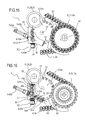
- FIGS. 13 and 14 are plan views and partial cross sections, respectively, of the filling unit according to the invention in a further embodiment
- FIGS. 15 and 16 are plan views and partial cross sections, respectively, of the filling unit according to the invention in a further embodiment
- FIG. 17 is a side view in partial cross section of the filling unit of FIGS. 15 and 16 ;
- FIG. 18 illustrates a variant embodiment of a detail of the filling unit of the preceding figures.
- the numeral 1 denotes a unit for filling containing elements of single-use capsules 3 for extraction or infusion beverages, with a dose 33 of solid product in powder, granules or leaves, such as coffee, tea, milk, chocolate, or combinations of these.
- the filling unit 1 is particularly suitable for filling containing elements of single-use capsules 3 with products in powder, preferably coffee.
- the single-use capsules 3 for extraction or infusion beverages comprise, in a minimum, but non-limiting, embodiment: a rigid, cup-shaped container 2 (usually to define a frustoconical shape) comprising a base 30 and an upper opening 31 equipped with a collar 32 ; a dose 33 of extraction or infusion product contained in the rigid container 2 and a lid 34 for closing the upper opening 31 of the rigid container 2 .
- this type of capsule 3 may also comprise one or more filtering or product retaining elements (not illustrated here for simplicity reasons).
- the rigid, cup-shaped container 2 defines the containing element to be filled with a dose 33 of product.
- capsules may be filled with the filling unit according to the invention, for example capsules wherein the dose 33 of product is contained in, and retained by, a filtering element connected to the rigid container, wherein the rigid container can be closed at the bottom, or open.
- a filtering element may contain and retain the dose 33 of product, forming the containing element in combination with the rigid container with which it is coupled.
- the invention can be made with reference to capsules wherein the containing element is formed by a filtering element (or other components of the capsule designed to contain a dose 33 of product) and by the respective rigid container to which it is connected.
- the filling unit 1 comprises a line 4 for transport (that is to say, movement) of rigid, cup-shaped containers 2 designed to contain a predetermined quantity of extraction or infusion product (dose 33 ) and a filling station SR.
- the transport line 4 extends along a first movement path P and is provided with a plurality of seats 5 for supporting the rigid containers 2 , arranged in succession along the first path P.
- the first movement path P is a closed path lying on a horizontal plane.
- the supporting seats 5 are arranged one after another, not necessarily continuously, along the first path P.
- the supporting seats 5 each have a corresponding vertical axis of extension.
- the transport line 4 comprises a transport element 39 to which the supporting seats 5 are connected to be moved along the first path P.
- transport element 39 is closed in a loop around movement means 17 which rotate about vertical axes for moving the transport element 39 .
- the transport element 39 is a chain 40 comprising a plurality of links, hinged to one another in succession about corresponding vertical axes, to form an endless loop.
- At least one of the links comprises at least one supporting seat 5 with a vertical axis for corresponding rigid container 2 which can be positioned with the opening 31 facing upwards.
- the chain 40 may comprise both links having a corresponding supporting seat 5 and connecting links which are not provided with supporting seats 5 and which are interposed between links provided with supporting seats 5 .
- a certain number of links comprises each supporting seat 5 .
- the movement means 17 rotate continuously about vertical axes to allow the transport element 39 to move continuously.
- SR for filling the rigid, cup-shaped containers 2 .
- the station SR for filling the rigid, cup-shaped containers 2 comprises:
- the release device comprises at least one rotary unit, designed to rotate about a respective axis of rotation to release the product inside the at least one first containing seat. All the above-mentioned components forming part of the filling station SR of the rigid, cup-shaped containers 2 are described below in more detail, with particular reference to the accompanying drawings.
- the devices 7 for moving the first containing seat S 1 comprise a first element 9 rotating about a first axis X 1 of rotation which is substantially vertical, on which is connected the first containing seat S 1 to be rotated about the first vertical axis X 1 of rotation.
- the first rotary element 9 comprises a wheel 9 a , connected to respective means for driving the rotation.
- the filling station SR comprises a plurality of first seats S 1 .
- the first seats S 1 are connected radially to the first rotary element 9 (more precisely to the wheel 9 a ) to be rotated with it.
- the first seats S 1 are made directly in the first rotary element 9 , in particular they are made directly in the wheel 9 a.
- first seats S 1 are positioned along an arc of a circle, preferably along a circumference having as the centre a point of the first axis X 1 .
- the first seats S 1 are angularly equispaced from each other along a circumference having as the centre a point of the first axis X 1 .
- each first seat S 1 follows a second path P 1 different from the first path P, preferably circular having as the axis of rotation the first axis X 1 in such a way as to engage cyclically—during rotation—the substations for forming (ST 1 ) and transferring (ST 2 ) the dose.
- first seats S 1 are connected to the first rotary element 9 by means of a rod (not illustrated), which is movable radially relative to the first rotary element 9 .
- Each first seat S 1 is defined, preferably, by lateral walls of a cavity 18 and by a bottom wall F.
- the cavity 18 is a cylindrical cavity.
- the cavity 18 has a vertical axis of extension (parallel to the first axis X 1 of rotation).
- the filling station SR comprises, for each first seat S 1 :
- Examples of movement means 14 are electric motors, pneumatic devices, cam devices, and other prior art devices.
- the expression “the piston 13 fully occupies the space” means that the piston 13 is positioned in the seat so as not to allow the presence of the dose 33 inside the first seat S 1 .
- the filling station SR comprises movement means 14 which are independent for each piston 13 , so that each piston can be moved independently of the others.
- the cavities 18 are through cavities and the pistons 13 are movable in a linear fashion inside the cavities 18 , for varying the space of the first seats S 1 (lower position) and for expelling the doses 33 from the first seats S 1 (upper position).
- the forming ST 1 and transfer ST 2 substations are positioned along the periphery of the first rotary element 9 in such a way as to be engaged cyclically by the first seats S 1 during rotation around the first axis X 1 .
- the forming ST 1 and transfer ST 2 substations are arranged in a predetermined position relative to a frame 29 of the filling station SR, along the second movement path P 1 of the first seat S 1 .
- each of the first seats S 1 is positioned in the forming substation ST 1 and, subsequently, in the transfer substation ST 2 .
- the second movement path P 1 is closed.
- the second movement path P 1 is a circular path around the first axis X 1 .
- the second path P 1 lies on a horizontal plane.
- substation ST 1 for forming the dose 33 .
- the substation ST 1 for forming the dose 33 is positioned in a region R 1 for forming the dose 33 .
- the release device 6 designed for releasing a predetermined quantity of product (defining the dose 33 ) inside the containing seat S 1 positioned in the region R 1 for forming the dose 33 .
- the releasing device 6 comprises a hopper 38 (filled, in use, with product) having at the bottom an outfeed 19 for the product.
- the outfeed 19 is located immediately above the containing seat S 1 at the region R 1 for forming the dose 33 .
- the outfeed 19 is configured to create a layer of product at the region R 1 for forming the dose 33 above the first seats S 1 , so as to release the product inside the first seat(s) S 1 positioned, each time, in the forming region R 1 .
- the outfeed 19 of the hopper 38 is shaped in such a way as to occupy a portion of the second movement path P 1 of the first seats S 1 .
- the outfeed 19 is in the form of a arc, centred on the first axis X 1 .
- the outfeed 19 in the shape of an arc has a plan width substantially equal to the diameter of the containing seats S 1 , so as to avoid build-ups of product inside the hopper 38 .
- the outfeed 19 of the hopper 38 releases the product at a plurality of first seats S 1 positioned temporarily in the region R 1 , that is to say, opposite below the outfeed 19 .
- the piston 13 occupies the lower position in at least one stretch of the region R 1 for forming the dose 33 .
- the first seats S 1 passing below the hopper 38 , are filled with product, in a filling time which depends on the speed of transit of the first seats S 1 in the forming region R 1 and on the amplitude of the portion of the second movement path P 1 of the first seats S 1 occupied by the outfeed 19 of the hopper 38 .
- the movement of the piston 13 in the region R 1 for forming the dose the following should be noted.
- the piston 13 associated with the first seat S 1 is positioned in the upper position where it prevents the filling of the first seat S 1 (in this upper position the piston 13 closes the top of the seat 18 which defines the first seat S 1 ) until the first seat S 1 has completely entered inside the region R 1 for forming the dose, at an infeed zone of the region R 1 for forming the dose.
- the piston 13 associated with the first seat S 1 is moved from the upper position to a lower end position.
- the first seat S 1 is therefore filled not only by gravity acting on the product which causes the product to enter the seat S 1 but also due to the suction effect on the product caused by the movement (displacement) of the piston 13 from the upper position to the lower end position.
- the resulting speed of the machine 100 at the filling station SC, in particular at the substation ST 1 for forming the dose is particularly high.
- the first seat S 1 defines a first space.
- the piston 13 associated with the seat S 1 may advantageously be moved from the lower end position to a dosing position, located between the lower end position and the upper position.
- the piston 13 in the above-mentioned dosing position, forms with the side walls of the first seat S 1 a predetermined space for containing a desired quantity of product (this space is less than the first space which is defined at the lower end position).
- the fact of having firstly the piston in the lower end position, in which it defines a first containment space, and then the piston 13 in the dosing position means that the powder deposited inside the first seat S 1 undergoes a first compression in the region R 1 for forming the dose.
- the first compression contributes to rendering uniform the placing the powder inside the seat and increasing the apparent density of the powder.
- the release device 6 comprises at least a first rotary element 40 a , designed to rotate about its axis of rotation X 4 .
- the axis of rotation X 4 of the first rotary element 40 a is stationary relative to the hopper 38 , or equally, to the frame 29 .
- the first rotary element 40 a is configured to create a flow of product flowing out from the outfeed 19 of the hopper 38 which intercepts the at least one first seat S 1 and to release the product inside the at least one first containing seat S 1 in transit through the region R 1 for forming the dose.
- the flow of product intercepts the at least one first seat S 1 at the infeed zone of the region R 1 for forming the dose.
- the first rotary element 40 a is operating in the region R 1 for forming the dose on a plurality of seats S 1 simultaneously (on the seats S 1 temporarily in transit through the forming region R 1 ).
- the first rotary element 40 a is operating in the region R 1 for forming the dose 33 , to release the product inside the first containing seat S 1 in transit through the region R 1 .
- the release device 6 also comprises drive means (such as, for example, a first drive unit 43 a ), operatively coupled to the first rotary element 40 a to rotate the rotary element 40 a.
- drive means such as, for example, a first drive unit 43 a
- the first rotary element 40 a preferably comprises an element 41 a which defines a surface with a helical extension.
- the helical surface extends—in a spiral shape—along the axis of rotation X 4 of the first rotary element 40 a.
- the first rotary element 40 a also comprises a respective first shaft 42 a , to which the element 41 a is connected, defining a surface with a helical extension for being rotated.
- the first shaft 42 a is supported rotatably relative to the frame of the filling unit 1 .
- the first shaft 42 a extends along the axis of rotation X 4 of the first rotary element 40 a.
- first rotary element 40 a described above defines a screw feeder, which by rotation about the axis of rotation X 4 allows a feeding of the product along the direction defined by the axis of rotation X 4 .
- the axis of rotation X 4 of the first rotary element 40 a is horizontal.
- the axis of rotation X 4 of the first rotary element 40 a is vertical.
- the axis of rotation X 4 of the first rotary element 40 a is inclined relative to a horizontal plane. It should be noted that, in this alternative embodiment, the product is fed by the first rotary element 40 a angularly, according to the direction of extension of the axis of rotation X 4 so that the motion of the product has, as well as a horizontal component, a vertical component which favours the insertion of the product inside the first seat S 1 in transit through the region R 1 for forming the dose (slightly compressing the product inside the first seat S 1 ).
- the fact that the axis X 4 of the first rotary element 40 a is angularly positioned makes it possible to optimize the filling the first seat S 1 .
- the helical element 41 a of the first rotary element 40 a comprises a first end, positioned at the infeed zone of the region R 1 for forming the dose, and a second end opposite to the first end.
- the helical element 41 a of the first rotary element 40 a is rotated in such a way that the product is pushed, along the direction of extension of the axis of rotation X 4 , in the direction from the second end towards the first end.
- the rotation of the helical element 41 a of the first rotary element 40 a creates a flow of product inside the hopper 38 , which intercepts the first seat S 1 to be filled, so that the first seat S 1 is filled at the first end of the helical element 41 a.
- the first end of the helical element 41 a is positioned at the infeed zone of the region R 1 for forming the dose.
- the first rotary element 40 a pushes the product from a zone inside the region R 1 for forming the dose towards the infeed area of the region R 1 for forming the dose.
- the first rotary element 40 a defines a unit for feeding the product inside the first seat S 1 .
- FIGS. 15 to 17 illustrate a variant embodiment in which the release device 6 comprises, in addition to the first rotary element 40 a , a second rotary element 40 b , designed to rotate about a relative further axis of rotation X 5 .
- the release device 6 also comprises drive means (such as, for example, a second drive unit 43 b ), operatively coupled to the second rotary element 40 b to rotate the second rotary element 40 b.
- drive means such as, for example, a second drive unit 43 b
- the further axis of rotation X 5 of the second rotary element 40 b is stationary relative to the hopper 38 , or, equally, to the frame 29 .
- the second rotary element 40 b is designed to create a recycle flow of product.
- each of the two rotary elements ( 40 a , 40 b ) is equipped with a respective helical element ( 41 a , 41 b ) and a respective shaft ( 42 a , 42 b ), to which a respective helical is connected for being rotated.
- the second shaft 42 b is supported rotatably relative to the frame of the filling unit 1 .
- the second shaft 42 b extends along the further axis of rotation X 5 of the second rotary element 40 b.
- the second rotary element 40 b described above defines a screw feeder, which by rotation about the further axis of rotation X 5 allows a feeding of the product along the direction of axial extension defined by the further axis of rotation X 5 .
- the shafts ( 42 a , 42 b ) of the first and the second rotary element ( 40 a , 40 b ) are offset from each other.
- the shafts ( 42 a , 42 b ) of the first and the second rotary element ( 40 a , 40 b ) are positioned at different heights to each other.
- the shaft 42 a of the first rotary element 40 a is positioned below the second shaft 42 b of the second rotary element 40 b (as is shown in FIG. 17 ).
- the shafts ( 42 a , 42 b ) of the first and the second rotary element ( 40 a , 40 b ) are superposed on each other at a superposing zone.
- the helical element 41 b of the second rotary element 40 b extends between a first end, positioned at an outfeed zone of the region R 1 for forming the dose, and a second end opposite the first.
- the second end of the helical element 41 b is positioned, starting from the outfeed zone of the transfer region R 1 , upstream of the superposing zone of the two shafts ( 42 a , 42 b ): this means that the respective helical elements ( 41 a , 41 b ) of the first rotary element 40 a and the second rotary element 40 b can freely rotate, without interfering with each other.
- the shaft 42 b of the second rotary element 40 b is positioned horizontally, or at an angle to a horizontal plane.
- both the first shaft 42 a of the first rotary element 40 a , and the second shaft 42 b of the second rotary element 40 b are positioned horizontally.
- the second shaft 42 b of the second rotary element 40 b is positioned at an angle to a horizontal plane and the first shaft 42 a of the first rotary element 40 a is horizontal.
- the second shaft 42 b of the second rotary element 40 b is horizontal and the first shaft 42 a of the first rotary element 40 a is positioned at an angle to a horizontal plane.
- both the second shaft 42 b of the second rotary element 40 b and the first shaft 42 a of the first rotary element 40 a are positioned at an angle relative to a horizontal plane, advantageously mutually parallel.
- the second rotary element 40 b is rotated in such a way that the product is pushed along the direction of extension of the further axis of rotation X 5 in the direction from the first end towards the second end.
- the second rotary element 40 b pulls the product from the outfeed zone of the region R 1 for forming the dose towards a zone inside the region R 1 for forming the dose.
- the second rotary element 40 b recirculates the product which accumulates by the effect of a levelling element 22 (illustrated in more detail below), from the outfeed zone of the region R 1 for forming the dose to the first rotary element 40 a.
- the first rotary element 40 a performs dosing functions, whilst the second rotary element 40 b performs recycling functions.
- the second rotary element 40 b pulls the product along the direction of extension of the further axis of rotation X 5 from the outfeed zone of the region R 1 for forming the dose towards a zone inside the region R 1 for forming the dose, where the first rotary element 40 a is positioned; preferably, the second rotary element 40 b , pulls the product located above a predetermined height from the top edge defined by the first seat(s) S 1 .
- control unit 15 of the machine 100 is designed to rotate the at least one first rotary element 40 a of the release device 6 with a speed depending on the speed of movement of the first seat S 1 by the first rotary unit 9 about the first of rotation axis X 1 .
- control unit 15 of the machine 100 is designed to rotate the at least one first rotary element 40 a of the release device 6 with variable speed as a function of the quantity of product to be inserted inside each first seat S 1 . More in detail, it is possible to increase the quantity of product inserted inside each seat by increasing the speed of rotation of the first rotary element 40 a , in such a way as to increase the apparent density of the product, and vice versa.
- the rotary element ( 40 a , 40 b ) is associated with (located inside) the hopper 38 , which also forms part of the release device 6 .
- the hopper 38 is defined by corresponding side walls, which are vertical and/or inclined. More specifically, in the embodiment shown in FIGS. 15, 16 and 17 , the filling unit 1 comprises a hopper 38 to which the first rotary element 40 a and the second rotary element 40 b are associated (positioned inside).
- the filling unit 1 comprises a hopper 38 to which the first rotary element 40 a is associated (positioned inside).
- the presence of one or more rotary elements ( 40 a , 40 b ) prevents the product, in particular with powder type products (such as, for example, coffee), from creating blockages, that is, build-ups, inside the hopper which render incomplete the filling of the first seats S 1 in transit through the region R 1 for forming the dose.
- powder type products such as, for example, coffee
- the one or more rotary elements ( 40 a , 40 b ) are rotated so as to move the product and prevent the formation of any blockage inside the hopper 38 for feeding the product.
- the speed at which the unit 1 may be used is particularly high and, consequently, the unit 1 is particularly fast and reliable in its operation.
- the release device 6 is also equipped with a levelling device 22 , located in such a way as to prevent the product being dispersed out of the region R 1 for forming the dose 33 , except for the product contained in the first seats S 1 , that is, the individual doses 33 .
- the levelling element 22 and the piston 13 define the dose 33 contained in the first seats S 1 .
- the movement means 14 are designed to position the piston 13 in a dosing position, located between the lower position and the upper position, at the outfeed zone of the region R 1 for forming the dose 33 , to define the dose 33 in conjunction with the levelling element 22
- the filling station SR comprises a substation ST 4 for compacting the dose 33 .
- the substation ST 4 for compacting the dose 33 is positioned in a compacting region R 4 , along the second movement path P 1 of the first seat S 1 between the forming substation ST 1 and the transfer substation ST 2 .
- the substation ST 4 is optional and can be omitted.
- the compacting substation ST 4 is equipped with compacting means 11 designed to compress the product, in phase with the piston 13 , inside the first seat S 1 .
- the compacting means 11 are described below in more detail.
- the compacting means 11 comprise a compacting element 28 .
- the compacting element 28 in the preferred embodiment illustrated comprises a compacting disk 23 .
- the compacting element 28 is connected to the (carried by the) frame 29 of the filling station SR.
- the compacting element 28 is positioned on top of the first seats S 1 at the compacting region R 4 .
- the compacting element 28 comprises an upper face and a lower face.
- the lower face is a planar face.
- the lower face of the compacting element 28 defines, at the compacting region R 4 , an upper contact element of the dose 33 positioned inside the first seat S 1 , so as to compact the product, when the piston 13 is lifted into a compacting position, which is intermediate between the lower position and the upper position.
- the means 14 for moving the piston 13 are designed to move the piston 13 from the lower position to the compacting position, that is to say, to bring the piston 13 towards the compacting element 28 , in the compacting region R 4 , in such a way as to compact the dose 33 .
- the compacting element 28 is stationary relative to the frame 29 .
- the compacting element 28 is rotatably carried (supported) by the frame 29 of the filling station SR, so as to rotate about a third axis X 3 of rotation.
- the compacting element 28 is freely rotatable about the third axis X 3 .
- the filling station SR comprises a drive system operatively connected to the compacting element 28 for driving the compacting element 28 in rotation about the third axis X 3 . It should be noted that, in this embodiment, the drive unit is driven in synchrony with the first rotary element 9 .
- the fact that it comprises a unit for driving the compacting element 28 means that it is possible—with suitable relative speeds of rotation of the compacting element 28 and of the first rotary element 9 —to minimise the speed of contact between the dose 33 inside the first seat S 1 and the compacting element 28 in the compacting region R 4 .
- the filling station SR is described below with particular reference to the second seat S 2 , the transfer substation ST 2 and the release substation ST 3 .
- the filling station SR comprises, preferably, a second rotary element 10 to which the second seat S 2 is associated (connected).
- the second rotary element 10 forms the above-mentioned further devices 8 for moving the second seat S 2 between the transfer substation ST 2 and the release substation ST 3 and vice versa.
- the second rotary element 10 is configured to rotate about a second axis X 2 .
- the second axis is parallel to the first axis X 1 . More preferably, the second axis X 2 is vertical.
- the filling station SR comprises a plurality of second seats S 2 .
- the second seat(s) S 2 are connected to the second rotary element 10 so as to be rotated by it.
- the second rotary element 10 comprises, preferably, a second wheel 10 a , configured to rotate about the second axis X 2 , to which the second seats S 2 are connected.
- the second seats S 2 in the embodiment illustrated are moved along a third path P 2 , substantially circular, different from the second path P 1 . More generally, the third path P 2 is closed. Preferably, the third path P 2 lies on a plane (horizontal).
- the third path P 2 is partly superposed and, at the release region R 3 , parallel to the first path P.
- each second seat S 2 is moved in a complete a rotation about the second axis X 2 , or more generally, around the third path P 2 , to the transfer station ST 2 (in a transfer region R 2 ) and to the release station ST 3 (in a release region R 3 ).
- the second seat S 2 is positioned above, advantageously immediately above, the first seat S 1 .
- the piston 13 is driven upwards for pushing the dose 33 of product from the first seat S 1 to the second seat S 2 .
- this seat is a through seat.
- the second seat S 2 is preferably defined by a through cavity (preferably in the form of a hole).
- the cavity is cylindrical.
- side walls of the second seat S 2 are defined by side walls of the through cavity.
- the second seat S 2 is connected to the second rotary element 10 by means of a rod 27 .
- the second seat S 2 is fixed to the second rotary element 10 , that is, to the second wheel 10 a.
- the radial position of the second seat S 2 is constant relative to the second axis X 2 .
- the third path P 2 is circular.
- the plan extension of the second seat S 2 is greater than the plan extension of the first seat S 1 (in such a way that whilst the dose 33 of product fully occupies the space of the first seat S 1 , the dose 33 of product after the transfer does not fully occupy the space of the second seat S 2 ).
- plan extension of the second seat S 2 is greater than plan extension of the first seat S 1 allows, in use, the transfer of the dose 33 from the first seat S 1 to the second seat S 2 in a transfer region R 2 which is sufficiently large.
- This is particularly important for speeds of rotation of the first rotary element 9 and of the second rotary element 10 which are particularly high: in effect, the above-mentioned aspect ensures that the superposing of the second seat S 2 on the first seat S 1 and, therefore, the transfer of the dose 33 the first seat S 1 to the second seat S 2 can occur in predetermined angles of rotation of the first and the second rotary elements.
- each second seat S 2 is movable relative to the second rotary element 10 , that is, relative to the second wheel 10 a.
- each second seat S 2 is movable on a plane at right angles to the second axis X 2 .
- each second seat S 2 is movable at least radially relative to the second axis X 2 . Therefore, in the embodiment illustrated, the third path P 2 , at the transfer region R 2 , is parallel to the second path P 1 .
- the fact that the second seat S 2 is movable on a plane at right angles to the second axis X 2 makes it possible to extend the extension of the transfer region R 2 : in other words, it is possible to extend the zone where the second seat S 2 superposes the first seat S 1 .
- the transfer of the dose 33 from the first seat S 1 to the second seat S 2 is not instantaneous but is performed within an angle of rotation of the first rotary element 9 and of the second rotary element 10 .
- the fact that the second seat S 2 is movable radially relative to the second rotary element 10 allows a tracking of the first seat S 1 during rotation of one or both the rotary elements ( 9 , 10 ), so that it is possible to keep the second seat S 2 superposed on the first seat S 1 through an angle of rotation of the first rotary element 9 and the second rotary element 10 which is sufficiently large to allow the dose 33 to be transferred from the first seat S 1 to the second seat S 2 .
- plan extension of the second seat S 2 may be reduced with respect to the embodiment (not illustrated) wherein the second seat S 2 is fixed to the second rotary element 10 , that is, to the second wheel 10 a.
- the piston 13 supports the dose 33 .
- each second seat S 2 is movable relative to the second rotary element 10 that is, relative to the second wheel 10 a both radially and in rotation about axes which are parallel to the second axis X 2 , that is, about vertical axes.
- cam means may move the second seats S 2 radially and in rotation relative to the second rotary element 10 that is, relative to the second wheel 10 a.
- each second seat S 2 has two degrees of freedom on horizontal planes which allow the second seats S 2 to perfectly follow the first seats S 1 in the transfer region R 2 .
- each second seat S 2 is exactly superposed on a corresponding first seat S 1 in the transfer region R 2 .
- the first seats S 1 and the second seats S 2 can have a plan extension which is equal.
- the second rotary element 10 and the transport element 39 are positioned in such a way that a portion of the first path P of the supporting seats 5 is—according to a plan view—superposed on a portion of the third path P 2 of the second seats S 2 .
- the superposed portions of the path between supporting seats 5 and second seats S 2 are curvilinear portions of the path (preferably arcs).
- the release substation ST 3 is positioned at the portions of the path superposed.
- the transfer of the dose 33 from the second seat S 2 to the rigid, cup-shaped container 2 might also occur at a rectilinear portion of the first movement path P of the supporting seats 5 , that is to say, a rectilinear portion of the movement line 4 of the rigid, cup-shaped container 2 .
- the second seats S 2 are movable at least radially relative to the second wheel 10 a , in such a way as to maintain the superposing of the second seat S 2 with the rigid, cup-shaped container 2 at a rectilinear stretch of the line 4 which is sufficiently large.
- the movement (at least radial) of the second seat S 2 relative to the second wheel 10 a /second rotary element 10 ensures that the second seat S 2 , during rotation of the second rotary element 10 , remains superposed on the rigid, cup-shaped container 2 being fed in the transport line 4 for a rectilinear stretch sufficiently long to allow the dose 33 to be released from the second seat S 2 to the underlying rigid, cup-shaped container 2 .
- the filling station SR also comprises an upper contact element 25 , present in the transfer region R 2 , which defines an upper stop for the dose 33 (as described in more detail below).
- the upper contact element 25 is a substantially planar plate.
- the upper contact element 25 is fixed to the frame 29 of the filling station SR, that is, it is not rotated as one with the second rotary element 10 .
- the upper contact element 25 is positioned in the transfer region R 2 above the second seat S 2 .
- the filling station SR also comprises a supporting element 24 positioned along the third path P 2 between the transfer substation ST 2 and the release substation ST 3 .
- the supporting element 24 forms a base for each second seat S 2 , at the portion of the third path P 2 where the supporting element 24 is positioned: this will become clearer below, where the operation of the filling unit according to this invention and the method according to this invention are described.
- the filling station SR may comprise, advantageously, according to the embodiment illustrated, one or more pushing elements 26 .
- the pushing elements 26 are optionals and can be omitted. Note: it is basically a rotary ejection device.
- the pushing element(s) 26 is/are movable, the operate(s) on the second seat S 2 at the release substation ST 3 .
- the filling station SR comprises a pushing element 26 associated with each second seat S 2 .
- the filling station SR comprises a plurality of pushing elements 26 , one for each second seat S 2 .
- pushing elements 26 are integral with the second rotary element 10 , in such a way as to be rotated with it.
- the pushing element 26 is movable between a raised position, in which it is positioned above and outside the second seat S 2 , and a lowered position, where it protrudes below the second seat S 2 .
- the pushing element 26 may be sized in such a way as to bring about a cleaning of the second seat S 2 during the passage from the raised position to the lowered position.
- the filling station SR comprises drive means, for example cam drive means, for moving the pushing element 26 between the raised position and the lowered position.
- the pushing element 26 passing from the raised position to the lowered position, comes into contact with the side of the side walls of the second seat S 2 , thereby cleaning the side walls.
- the pushing element 26 is moved from the raised position to the lowered position at the release substation ST 3 (after, or during, the release of the product), in the manner described in more detail below.
- the pushing element 26 pushes, from the top downwards, and towards the outside, the dose 33 positioned inside the second seat S 2 , with the aim of favouring the transfer of the dose 33 from the second seat S 2 to the rigid, cup-shaped container 2 .
- the release substation ST 3 equipped with pushing elements 26 is extremely clean, more so than a station with screw feeders.
- This single pushing element 26 is movable in order to make contact—at the end or during the step of releasing the dose 33 from the second seat S 2 to the rigid container 2 —with the side walls of the second seat S 2 so as to carry out a cleaning.
- the unit 1 also comprises a unit (formed by one or more electronic cards) for drive and control of the devices ( 7 , 8 ) for moving, respectively, the first seat S 1 and the second seat S 2 .
- the drive and control unit is also configured to control the advance of the transport element 39 and the movable elements of the filling station SR (for example, the pistons 13 , the pushing elements 26 ).
- the drive and control unit coordinates and controls the step of moving all the above-mentioned elements connected to it, so as to allow the operations described below to be performed.
- the filling unit 1 may advantageously form part of a packaging machine 100 (illustrated in FIG. 1 ) designed for packaging single-use capsules for extraction or infusion beverages, for example of the type described above.
- the packaging machine 100 further comprises a plurality of stations, positioned along the first path P performed by the transport element 39 , configured to operate in a synchronised fashion (preferably continuously) with the transport element 39 and with the filling station SR, comprising at least:
- the packaging machine 100 may comprise further stations, such as, for example, one or more weighing stations, one or more cleaning stations, one or more control stations and, depending on the type of capsule to be packaged, one or more stations for applying filtering elements.
- the filling unit 1 is briefly described below, in particular the filling station SR, with the aim of clarifying the scope of the invention: in particular, the filling of a rigid, cup-shaped container 2 is described with reference to the embodiment illustrated in the accompanying drawings.
- a first seat S 1 designed to be filled with a dose 33 of product is positioned in the region R 1 for forming the dose 33 , that is to say, in the proximity of the station ST 1 for forming the dose 33 .
- the hopper 38 feeds product in the region R 1 for forming the dose 33 , which falls in, and fills, the first seat S 1 .
- the movement of the first rotary element 9 is, preferably, a continuous type movement. Alternatively, the movement of the first rotary element 9 is of a step type.
- the first seat S 1 is completely filled at the outfeed of the region R 1 for forming the dose 33 .
- the levelling device 22 allows excess product (for example, powder or leaves) to be removed, in such a way that the first seat S 1 is completely filled, or in other words, that the dose 33 comprises a surface formed by the levelling device 22 .
- the filling unit 1 can operate a step for compacting the dose 33 .
- the compacting step is optional and can be omitted.
- the compacting step if present, when the first seat S 1 is positioned—by the rotation of the first rotary element 9 —at the compacting substation ST 4 , the dose 33 of product inside the first seat S 1 is subjected to compacting.
- the dose 33 of product inside the first seat S 1 is pushed by the piston 13 upwards when the piston 13 is raised from the lower position to the compacting position, so that an upper part of the dose 33 makes contact with a lower face of the compacting disk 23 , and the dose 33 is compacted inside the first seat S 1 . It is clear that the more the piston 13 is raised, that is to say, moved close to the compacting disk 23 , the more the dose 33 is compacted.
- the first seat S 1 is positioned at the transfer region R 2 , in which the transfer substation ST 2 is present.
- a second seat S 2 is positioned at the transfer region R 2 , for receiving the dose 33 from the first seat S 1 .
- FIGS. 9 to 12 illustrate—in a side view—a sequence of operations which are performed at the transfer region R 2 .
- first rotary element 9 and the second rotary element 10 are moved during transfer of the dose 33 of product from the first seat S 1 to the second seat S 2 .
- the first rotary element 9 and the second rotary element 10 are, preferably, driven continuously.
- the piston 13 is moved from the lowered position, wherein it defines the bottom F the first seat S 1 , to the raised position, so as to transfer the dose 33 from the first seat S 1 to the second seat S 2 .
- the second seat S 2 and the first seat S 1 are superposed (at different heights) at the transfer region R 2 .
- the second seat S 2 is positioned above the first seat S 1 .
- the area occupied in plan by the first seat S 1 is positioned inside the area occupied in plan by the second seat S 2 (however, the first seat S 1 and second seat S 2 are positioned at different heights: the second seat S 2 is positioned higher than the first seat S 1 as shown in the accompanying FIGS. 9 to 11 ).
- the step of transferring the dose 33 of product from the first seat S 1 to the second seat S 2 comprises a step for pushing the dose 33 , using the piston 13 , from the first seat S 1 to the second seat S 2 ( FIG. 10 ).
- the upper contact element 25 present at the transfer region R 2 , defines an upper stop for the dose 33 of product, in such a way as to substantially prevent the escape of the dose 33 of product from the second seat S 2 following the pushing action of the piston 13 (as illustrated in FIG. 11 ).
- the upper contact element 25 is fixed to the frame 29 of the machine, that is, it is not rotated as one with the second rotary element 10 .
- the piston 13 in the position of escape from the first seat S 1 defines, temporarily, the bottom of the second seat S 2 that is, it allows the product to be supported inside the second seat S 2 .
- the further rotation of the second rotary element 10 ensures that the second seat S 2 makes contact with the bottom of the supporting element 24 .
- the supporting element 24 therefore replaces the piston 13 in defining the bottom of the second seat S 2 .
- the first seat S 1 following the further rotation of the first rotary element 9 , is positioned again at the forming station ST 1 of the dose 33 , where the piston 13 again adopts the lower position in which it defines the bottom of the first seat S 1 .
- the supporting element 24 is fixed to the frame 29 of the machine, that is, it is not rotated as one with the second rotary element 10 .
- the dose 33 positioned inside the second seat S 2 , is supported below by the supporting element 24 for a predetermined angular stroke of the second rotary element 10 and moved from the second seat S 2 along the third path P 2 .
- the dose 33 of product inside the second seat S 2 slides on, and is supported by, the supporting element 24 for a predetermined angular stroke of the second rotary element 10 .
- the dose 33 is released from the second seat S 2 to a rigid, cup-shaped container 2 positioned, at the release substation ST 3 , below the second seat S 2 .
- the release substation ST 3 extends along a predetermined portion of the third movement path P 2 of the second seats S 2 .
- the releasing step is performed preferably whilst the second element 10 is in rotation and the transport line 4 is actuated, that is to say, whilst both the second seat S 2 and the rigid, cup-shaped container 2 are moved.
- the release step is described below.
- the second seat S 2 is superposed on the cup-shaped container 2 , so that it is possible to transfer—by falling, or pushing, from the top downwards—the dose 33 from the second seat S 2 to the cup-shaped container 2 .
- the release of the dose 33 from the second seat S 2 to the cup-shaped container 2 is achieved simply by dropping the dose 33 by gravity once the second seat S 2 is superposed on the cup-shaped container 2 , and the supporting element 24 has ended and no longer supports the dose 33 .
- the pushing element 26 penetrates—from the top downwards—into the second seat S 2 , in such a way as to scrape the side walls of the second seat S 2 in order to exert a cleaning action.
- the pushing element 26 may exert a pushing action—from the top downwards—on the dose 33 of product inside the second seat S 2 , in such a way as to favour the escape of the dose 33 from the second seat S 2 and allow the falling, that is, the release, inside the rigid, cup-shaped container 2 .
- the pushing element 26 penetrates—from the top—inside the second seat S 2 , pushing the dose 33 from the top downwards towards the rigid, cup-shaped container 2 .
- the action of the pushing element 26 therefore substantially has, in this case, a dual purpose: a cleaning of the second seat S 2 and the detachment and therefore the falling of the dose 33 of beverage from the second seat S 2 to the rigid, cup-shaped container 2 .
- the pushing element 26 is again moved towards the raised position, in such a way as to disengage the second seat S 2 which is moved, by the rotation of the second rotary element 10 , towards the transfer substation ST 2 , so as to receive a new dose 33 of product.
- the second rotary element 10 is also driven substantially continuously.
- both the first rotary element 9 and the second rotary element 10 may be operated in a step-like fashion.
- the step of transferring the dose 33 from the first seat S 1 to the second seat S 2 is performed with the first rotary element 9 and the second rotary element 10 stationary.
- the dose 33 inside the rigid cup-shaped container is moved, by the movement of the transport line 4 , towards successive stations, comprising for example, the closing station SC (not described in detail).
- the filling unit 1 according to this invention is particularly simple in terms of construction and at the same time is extremely flexible, and can easily adapt to different types of products and capsules.
- the filling unit 1 differs from those described above in terms of the following aspects and which concern the release device 6 .
- the release device 6 comprises one or more, for example a pair of, rotary elements ( 40 a , 40 b ) rotating about respective axes of rotation (X 4 ; X 5 ) and a casing 66 .
- the rotary element ( 40 a , 40 b ) is equipped with a shaft 67 , extending along the axis of rotation (X 4 ; X 5 ); advantageously, the casing 66 extends along the same axis of rotation (X 4 ; X 5 ).
- the shaft 67 be is also movable along the axis of rotation (X 4 ; X 5 ).
- the axis of rotation (X 4 ; X 5 ) is positioned angularly inclined.
- the shaft 67 is movable relative to the casing 66 (defined below also as a tubular wrapping 66 ).
- the casing 66 is fixed to the frame 29 of the machine 100 and forms an internal chamber for containing the product to be fed to the seats S 1 .
- the casing 66 can form the hopper 38 , or it may be connected to the latter.
- the shaft 67 of the rotary element ( 40 a , 40 b ) is housed inside the casing 66 , at the product containment chamber.
- the rotary element ( 40 a , 40 b ), in particular the shaft 67 , is connected movably to the casing 66 , that is, to the tubular wrapping 66 (or, equally, to the frame 29 ), for moving (relative to the casing 66 ) along the axis of rotation (X 4 ; X 5 ).
- the drive unit 61 of the rotary element ( 40 a , 40 b ) is also movable (relative to the casing 66 ) along the axis of rotation (X 4 ; X 5 ) of the rotary element ( 40 a , 40 b ), as one with the shaft 67 of the rotary element ( 40 a , 40 b ).
- the drive unit 61 and the shaft 67 are movable as one along the axis of rotation (X 4 ; X 5 ) relative to the casing 66 .
- the filling device 6 also comprises, according to this aspect, elastic means 60 , operatively connected to the casing 66 and to the rotary element ( 40 a , 40 b ).
- the elastic means 60 are operatively interposed between the rotary element ( 40 a , 40 b ) on one side and the casing 66 on the other, so as to apply a return force on the rotary element ( 40 a , 40 b ).
- the elastic means 60 are configured to apply a return force on the rotary element ( 40 a , 40 b ), directed mainly along the axis of rotation (X 4 ; X 5 ) towards the first end E 1 .
- the elastic means 60 are compressed following a movement of the first end E 1 of the rotary element ( 40 a , 40 b ) away from the outfeed 19 of the hopper 38 (shift upwards).
- the deformation (in particular the compression) of the elastic means 60 as a result of movement of the rotary element ( 40 a , 40 b ) away from the outfeed 19 of the hopper 38 (shift upwards) generates a return force on the rotary element ( 40 a , 40 b ), directed along the axis of rotation (X 4 ; X 5 ) towards the outfeed 19 of the hopper 38 .
- the return force applies a pushing action on the rotary element ( 40 a , 40 b ) directed towards the outfeed 19 of the hopper 38 .
- the elastic means 60 comprise one or more springs ( 60 A, 60 B), interposed between the casing 66 and the rotary element ( 40 a , 40 b ).
- the spring(s) allow the shaft 67 of the rotary element ( 40 a , 40 b ) to be connected to the casing 66 .
- the spring(s) allow the shaft 67 and the drive unit 61 of the rotary element ( 40 a , 40 b ) to be connected to the casing 66 .
- the shaft 67 and the drive unit 61 of the rotary element ( 40 a , 40 b ) are integral with each other and during their movement in an axial direction deform (compress) the springs ( 60 A, 60 B).
- the rotary element ( 40 a , 40 b ) comprises a plate 62 fixed to the drive unit 61 , which is directly active on the springs ( 60 A, 60 B) and during the movement of the shaft 67 —drive unit 61 deforms (compresses) the springs ( 60 A, 60 B) in the direction of the axis of rotation (X 4 ; X 5 ) of the rotary element ( 40 a , 40 b ).
- each spring ( 60 A, 60 B) is positioned on the outside of a screw ( 63 A, 63 B) which is fixed to the casing 66 .
- each spring ( 60 A, 60 B) is mounted on the screw ( 63 A, 63 B) so as to abut the head of the screw ( 63 A, 63 B) at one end and the plate 62 at the other end.
- the rotary element ( 40 a , 40 b ) moves longitudinally along the axis of rotation (X 4 ; X 5 ) and, consequently, the pressure applied by the rotary element ( 40 a , 40 b ) towards the outfeed 19 of the hopper 38 is reduced.
- a predetermined value for example, on account of a product blockage close to the outfeed
- the pressure applied by the rotary element (or rotary elements) ( 40 a , 40 b ) on the product at the outfeed from the hopper 38 is substantially rendered uniform.
- the final technical effect is therefore that of filling the first seats S 1 with the same quantity of product, that is to say, reducing the variability regarding the quantity of product inserted inside the various seats S 1 .
- a device for releasing product for infusion or extraction beverages comprising:
- a method is also defined for filling containing elements of single-use capsules for extraction or infusion beverages.
- containing elements is deemed to mean both rigid, cup-shaped containers 2 , of the type shown, and elements for filtration or retention of a dose of product connected to a rigid container.
- the method according to the invention comprises the following steps:
- the step of moving a succession of containing elements along a first movement path P preferably comprises moving the containing elements along a first path P which is a closed loop lying on a horizontal plane.
- the succession of containing elements are moved with continuous motion.
- the step of moving the first containing seat S 1 of the product towards the transfer region R 2 comprises a rotation of the first seat S 1 about a first vertical axis X 1 .
- the step of moving the second containing seat S 2 of the product from the transfer region R 2 to the release region R 3 comprises a rotation of the second seat S 2 about a second vertical axis X 2 .
- the second seat S 2 and the first seat S 1 are superposed (positioned at different heights).
- the second seat S 2 is positioned above the first seat S 1 .
- the step of transferring the dose of beverage from the first seat S 1 to the second seat S 2 comprises a step of pushing (preferably using a piston 13 ) the dose 33 from the first seat S 1 to the second seat S 2 .
- the pushing step comprises pushing the dose 33 from the bottom upwards.
- the method comprises a step of compacting the dose 33 inside the first seat S 1 .
- the compacting step comprises pushing (preferably using a piston 13 ) the dose 33 against a compacting element 28 preferably comprising a fixed compacting disk 23 , which is rotatable in an idle fashion or rotatable in a motorised fashion about a vertical axis.
- the method comprises rotating about a respective further axis of rotation X 5 a further second rotating element 40 a to create a recycle flow of product from an exit zone of the region R 1 for forming the dose 33 to an internal zone of the same region R 1 for forming the dose 33 , where the first rotating element 40 a is positioned.
- the method described above is particularly simple and allows the creation of a dose 33 of product and the filling in a fast and reliable manner of a containing element, such as a rigid, cup-shaped container 2 , of a single-use capsule 3 for extraction or infusion beverages with the dose 33 of product.
Landscapes
- Engineering & Computer Science (AREA)
- Mechanical Engineering (AREA)
- Quality & Reliability (AREA)
- Basic Packing Technique (AREA)
- Auxiliary Devices For And Details Of Packaging Control (AREA)
Applications Claiming Priority (4)
| Application Number | Priority Date | Filing Date | Title |
|---|---|---|---|
| ITBO2013A0577 | 2013-10-18 | ||
| IT000577A ITBO20130577A1 (it) | 2013-10-18 | 2013-10-18 | Unita¿ e metodo di riempimento di elementi di contenimento di capsule monouso per bevande da estrazione o infusione. |
| ITBO2013A000577 | 2013-10-18 | ||
| PCT/IB2014/065041 WO2015056127A1 (en) | 2013-10-18 | 2014-10-03 | Unit and method for filling containing elements of single-use capsules for extraction or infusion beverages |
Publications (2)
| Publication Number | Publication Date |
|---|---|
| US20160229570A1 US20160229570A1 (en) | 2016-08-11 |
| US10173797B2 true US10173797B2 (en) | 2019-01-08 |
Family
ID=49585485
Family Applications (1)
| Application Number | Title | Priority Date | Filing Date |
|---|---|---|---|
| US15/029,500 Active 2035-12-01 US10173797B2 (en) | 2013-10-18 | 2014-10-03 | Unit for filling containing elements of single-use capsules for extraction or infusion beverages |
Country Status (7)
| Country | Link |
|---|---|
| US (1) | US10173797B2 (zh) |
| EP (1) | EP3057871B1 (zh) |
| JP (1) | JP2016537278A (zh) |
| CN (1) | CN106061847B (zh) |
| ES (1) | ES2660604T3 (zh) |
| IT (1) | ITBO20130577A1 (zh) |
| WO (1) | WO2015056127A1 (zh) |
Cited By (1)
| Publication number | Priority date | Publication date | Assignee | Title |
|---|---|---|---|---|
| US11401060B2 (en) * | 2017-05-26 | 2022-08-02 | Sacmi Cooperativa Meccanici Imola Societa Cooperativa | Method and apparatus for applying a sealing member to a capsule for preparing a beverage |
Families Citing this family (7)
| Publication number | Priority date | Publication date | Assignee | Title |
|---|---|---|---|---|
| ITBO20120338A1 (it) | 2012-06-20 | 2013-12-21 | Ima Ind Srl | Procedimento e macchina per formare componenti intermedi di capsule monouso per bevande |
| ITBO20120337A1 (it) * | 2012-06-20 | 2013-12-21 | Ima Ind Srl | Procedimento e macchina per formare capsule monouso per bevande |
| CN106132834B (zh) * | 2014-02-06 | 2019-01-08 | 吉玛股份公司 | 用于将萃取或泡制饮料的产品释放到形成一次性使用囊体或袋的容器的单元和方法 |
| WO2017025275A1 (en) * | 2015-08-11 | 2017-02-16 | Unilever N.V. | Powder filling device and filling method |
| IT201800009736A1 (it) * | 2018-10-24 | 2020-04-24 | Ima Industria Macch Automatiche Spa | Unità e metodo di trasferimento per contenitori monouso. |
| CA3183610A1 (en) * | 2020-08-05 | 2022-02-10 | G.D S.P.A. | Transfer device and process |
| CN113479360B (zh) * | 2021-06-10 | 2022-06-28 | 赣州市和裕实业有限公司 | 一种生产加工用茶叶定量装盒设备 |
Citations (23)
| Publication number | Priority date | Publication date | Assignee | Title |
|---|---|---|---|---|
| US2196403A (en) * | 1936-04-22 | 1940-04-09 | Fmc Corp | Filling machine |
| US2340637A (en) * | 1940-07-25 | 1944-02-01 | Fmc Corp | Filling machine |
| US2567052A (en) * | 1947-09-17 | 1951-09-04 | Eben H Carruthers | Method and apparatus for packing flake materials |
| GB672945A (en) * | 1949-07-21 | 1952-05-28 | Rose Brothers Ltd | Improvements in the packaging of powdery, granular and other fluent solid materials |
| US2644629A (en) * | 1946-05-08 | 1953-07-07 | James Q Leavitt Company | Can filling machine |
| US2689676A (en) * | 1947-12-10 | 1954-09-21 | Jl Ferguson Co | Method of measuring and filling accurately determinable amounts of products of widelyvarying character into containers and apparatus for practicing the same |
| US3026660A (en) * | 1960-04-01 | 1962-03-27 | Luthi Machinery & Engineering | Can filling machine |
| US3168121A (en) * | 1961-01-25 | 1965-02-02 | Parisienne D Expansion Chimiqu | Apparatus for dispensing doses of pulverulent material |
| US3179041A (en) * | 1963-09-16 | 1965-04-20 | Luthi Machinery & Engineering | Food canning machine |
| US3213901A (en) * | 1960-04-01 | 1965-10-26 | Luthi Machinery & Engineering | Can filling method |
| US3213587A (en) * | 1962-07-23 | 1965-10-26 | Eben H Carruthers | Method for packing compressible materials into containers |
| US3552454A (en) * | 1968-10-22 | 1971-01-05 | William A Deming Sr | Can filler |
| CH558739A (de) | 1971-12-13 | 1975-02-14 | Azionaria Costruzioni Acma Spa | Abgabevorrichtung fuer dosierte mengen pulverfoermigen materials. |
| US4107977A (en) * | 1974-10-01 | 1978-08-22 | Ijun Iosifovich Grinberg | Method of checking the valves of aerosol containers for tightness and an apparatus for effecting the same |
| DE2944494A1 (de) | 1979-11-03 | 1981-05-14 | Fa. Rich. Hengstenberg, 7300 Esslingen | Einrichtung zum dosierten beschicken von behaeltnissen, insbesondere konservenglaesern, mit gewuerzen |
| US4326568A (en) * | 1980-02-07 | 1982-04-27 | Rexham Corporation | Packaging machine with continuous motion filler |
| US5791127A (en) | 1995-11-10 | 1998-08-11 | G. Rossi Srl | Apparatus for the manufacture of ground coffee-powder bags |
| US5855233A (en) * | 1996-10-22 | 1999-01-05 | Dott. Bonapace & C.S.R.L. | Pulverulent substance dispensing device for capsule filling machines |
| US6425422B1 (en) * | 1998-12-03 | 2002-07-30 | I.M.A. Industria Macchine Automatiche S.P.A. | Dosing machine for hard gelatin capsules |
| US7610735B2 (en) * | 2007-03-14 | 2009-11-03 | Marchesini Group S.P.A. | Machine for packing stacks of disc-shaped articles inside rigid cylindrical containers |
| WO2010007633A1 (en) | 2008-07-14 | 2010-01-21 | Gima S.P.A. | Machine for packaging products, in particular capsules for machines for delivering infusion beverages |
| WO2013035061A2 (en) | 2011-09-08 | 2013-03-14 | Azionaria Costruzioni Macchine Automatiche A.C.M.A. S.P.A. | Machine for assembling, filling and sealing portioned beverage capsules |
| US20130318913A1 (en) * | 2012-06-05 | 2013-12-05 | Marchesini Group S.P.A | Device for transferring pharmaceutical articles from a counter to inside continuously advancing containers and a machine for packing pharmaceutical articles in relative containers |
Family Cites Families (5)
| Publication number | Priority date | Publication date | Assignee | Title |
|---|---|---|---|---|
| IT1279697B1 (it) * | 1995-12-07 | 1997-12-16 | Tecnomeccanica Srl | Macchina per confezionamento di insiemi per infusione in un liquido nei quali un prodotto infusibile e' contenuto in una busta filtro in |
| IT1292875B1 (it) * | 1997-04-23 | 1999-02-11 | Ima Spa | Apparecchiatura di confezionamento. |
| ITBO20030735A1 (it) * | 2003-12-05 | 2005-06-06 | Roberto Conti | Apparecchiatura per la formazione di cialde per prodotti da infusione |
| JP5230659B2 (ja) * | 2008-02-14 | 2013-07-10 | 不双産業株式会社 | 充填包装装置 |
| ITBO20120068A1 (it) * | 2012-02-15 | 2013-08-16 | Ima Ind Srl | Macchina per la formazione di capsule monouso per bevande |
-
2013
- 2013-10-18 IT IT000577A patent/ITBO20130577A1/it unknown
-
2014
- 2014-10-03 EP EP14786360.9A patent/EP3057871B1/en active Active
- 2014-10-03 WO PCT/IB2014/065041 patent/WO2015056127A1/en active Application Filing
- 2014-10-03 US US15/029,500 patent/US10173797B2/en active Active
- 2014-10-03 JP JP2016548444A patent/JP2016537278A/ja not_active Withdrawn
- 2014-10-03 CN CN201480069439.8A patent/CN106061847B/zh active Active
- 2014-10-03 ES ES14786360.9T patent/ES2660604T3/es active Active
Patent Citations (24)
| Publication number | Priority date | Publication date | Assignee | Title |
|---|---|---|---|---|
| US2196403A (en) * | 1936-04-22 | 1940-04-09 | Fmc Corp | Filling machine |
| US2340637A (en) * | 1940-07-25 | 1944-02-01 | Fmc Corp | Filling machine |
| US2644629A (en) * | 1946-05-08 | 1953-07-07 | James Q Leavitt Company | Can filling machine |
| US2567052A (en) * | 1947-09-17 | 1951-09-04 | Eben H Carruthers | Method and apparatus for packing flake materials |
| US2689676A (en) * | 1947-12-10 | 1954-09-21 | Jl Ferguson Co | Method of measuring and filling accurately determinable amounts of products of widelyvarying character into containers and apparatus for practicing the same |
| GB672945A (en) * | 1949-07-21 | 1952-05-28 | Rose Brothers Ltd | Improvements in the packaging of powdery, granular and other fluent solid materials |
| US3026660A (en) * | 1960-04-01 | 1962-03-27 | Luthi Machinery & Engineering | Can filling machine |
| US3213901A (en) * | 1960-04-01 | 1965-10-26 | Luthi Machinery & Engineering | Can filling method |
| US3168121A (en) * | 1961-01-25 | 1965-02-02 | Parisienne D Expansion Chimiqu | Apparatus for dispensing doses of pulverulent material |
| US3213587A (en) * | 1962-07-23 | 1965-10-26 | Eben H Carruthers | Method for packing compressible materials into containers |
| US3179041A (en) * | 1963-09-16 | 1965-04-20 | Luthi Machinery & Engineering | Food canning machine |
| US3552454A (en) * | 1968-10-22 | 1971-01-05 | William A Deming Sr | Can filler |
| CH558739A (de) | 1971-12-13 | 1975-02-14 | Azionaria Costruzioni Acma Spa | Abgabevorrichtung fuer dosierte mengen pulverfoermigen materials. |
| US4107977A (en) * | 1974-10-01 | 1978-08-22 | Ijun Iosifovich Grinberg | Method of checking the valves of aerosol containers for tightness and an apparatus for effecting the same |
| DE2944494A1 (de) | 1979-11-03 | 1981-05-14 | Fa. Rich. Hengstenberg, 7300 Esslingen | Einrichtung zum dosierten beschicken von behaeltnissen, insbesondere konservenglaesern, mit gewuerzen |
| US4326568A (en) * | 1980-02-07 | 1982-04-27 | Rexham Corporation | Packaging machine with continuous motion filler |
| US5791127A (en) | 1995-11-10 | 1998-08-11 | G. Rossi Srl | Apparatus for the manufacture of ground coffee-powder bags |
| US5855233A (en) * | 1996-10-22 | 1999-01-05 | Dott. Bonapace & C.S.R.L. | Pulverulent substance dispensing device for capsule filling machines |
| US6425422B1 (en) * | 1998-12-03 | 2002-07-30 | I.M.A. Industria Macchine Automatiche S.P.A. | Dosing machine for hard gelatin capsules |
| US7610735B2 (en) * | 2007-03-14 | 2009-11-03 | Marchesini Group S.P.A. | Machine for packing stacks of disc-shaped articles inside rigid cylindrical containers |
| WO2010007633A1 (en) | 2008-07-14 | 2010-01-21 | Gima S.P.A. | Machine for packaging products, in particular capsules for machines for delivering infusion beverages |
| WO2013035061A2 (en) | 2011-09-08 | 2013-03-14 | Azionaria Costruzioni Macchine Automatiche A.C.M.A. S.P.A. | Machine for assembling, filling and sealing portioned beverage capsules |
| US20140202120A1 (en) | 2011-09-08 | 2014-07-24 | Azionaria Costruzioni Macchine Automatiche A.C.M.A S.P.A | Machine for assembling, filling and sealing portioned beverage capsules |
| US20130318913A1 (en) * | 2012-06-05 | 2013-12-05 | Marchesini Group S.P.A | Device for transferring pharmaceutical articles from a counter to inside continuously advancing containers and a machine for packing pharmaceutical articles in relative containers |
Cited By (4)
| Publication number | Priority date | Publication date | Assignee | Title |
|---|---|---|---|---|
| US11401060B2 (en) * | 2017-05-26 | 2022-08-02 | Sacmi Cooperativa Meccanici Imola Societa Cooperativa | Method and apparatus for applying a sealing member to a capsule for preparing a beverage |
| US20220363417A1 (en) * | 2017-05-26 | 2022-11-17 | Sacmi Cooperativa Meccanici Imola Societa Cooperativa | Method and apparatus for applying a sealing member to a capsule for preparing a beverage |
| US11834219B2 (en) * | 2017-05-26 | 2023-12-05 | Sacmi Cooperativa Meccanici Imola Societa Cooperativa | Method and apparatus for applying a sealing member to a capsule for preparing a beverage |
| US20240059437A1 (en) * | 2017-05-26 | 2024-02-22 | Sacmi Cooperativa Meccanici Imola Societa Cooperativa | Method and apparatus for applying a sealing member to a capsule for preparing a beverage |
Also Published As
| Publication number | Publication date |
|---|---|
| WO2015056127A1 (en) | 2015-04-23 |
| JP2016537278A (ja) | 2016-12-01 |
| CN106061847B (zh) | 2017-12-26 |
| ITBO20130577A1 (it) | 2015-04-19 |
| EP3057871A1 (en) | 2016-08-24 |
| EP3057871B1 (en) | 2017-11-29 |
| US20160229570A1 (en) | 2016-08-11 |
| CN106061847A (zh) | 2016-10-26 |
| ES2660604T3 (es) | 2018-03-23 |
Similar Documents
| Publication | Publication Date | Title |
|---|---|---|
| US10173797B2 (en) | Unit for filling containing elements of single-use capsules for extraction or infusion beverages | |
| EP3102496B1 (en) | Unit and method for filling containers forming single-use capsules for extraction or infusion beverages | |
| EP3177539B1 (en) | Unit and method for filling containers of single-use capsules for extraction or infusion beverages | |
| EP3010811B1 (en) | Unit and method for filling containing elements of single-use capsules for extraction or infusion beverages | |
| EP3102490B1 (en) | Unit and method for releasing product for extraction or infusion beverages in containers forming single-use capsules or pods | |
| US10800562B2 (en) | Unit and method for filling containing elements of single-use capsules | |
| US11548670B2 (en) | Unit and method for filling containing elements of single-use capsules for extraction or infusion beverages | |
| CN114144153B (zh) | 用于填充胶囊的机器和方法 |
Legal Events
| Date | Code | Title | Description |
|---|---|---|---|
| AS | Assignment |
Owner name: GIMA S.P.A., ITALY Free format text: ASSIGNMENT OF ASSIGNORS INTEREST;ASSIGNORS:REA, DARIO;RUBBI, EMANUELE;CASTELLARI, PIERLUIGI;REEL/FRAME:038385/0244 Effective date: 20160426 |
|
| STCF | Information on status: patent grant |
Free format text: PATENTED CASE |
|
| CC | Certificate of correction | ||
| MAFP | Maintenance fee payment |
Free format text: PAYMENT OF MAINTENANCE FEE, 4TH YEAR, LARGE ENTITY (ORIGINAL EVENT CODE: M1551); ENTITY STATUS OF PATENT OWNER: LARGE ENTITY Year of fee payment: 4 |