US10167906B2 - Clutch assembly having a hydraulically actuate piston and latching device - Google Patents
Clutch assembly having a hydraulically actuate piston and latching device Download PDFInfo
- Publication number
- US10167906B2 US10167906B2 US15/214,041 US201615214041A US10167906B2 US 10167906 B2 US10167906 B2 US 10167906B2 US 201615214041 A US201615214041 A US 201615214041A US 10167906 B2 US10167906 B2 US 10167906B2
- Authority
- US
- United States
- Prior art keywords
- clutch member
- clutch
- piston
- axial direction
- selectively
- Prior art date
- Legal status (The legal status is an assumption and is not a legal conclusion. Google has not performed a legal analysis and makes no representation as to the accuracy of the status listed.)
- Active, expires
Links
- 238000000034 method Methods 0.000 claims abstract description 9
- 230000005540 biological transmission Effects 0.000 claims description 34
- 239000012530 fluid Substances 0.000 claims description 11
- 230000008878 coupling Effects 0.000 claims description 5
- 238000010168 coupling process Methods 0.000 claims description 5
- 238000005859 coupling reaction Methods 0.000 claims description 5
- 241000381592 Senegalia polyacantha Species 0.000 claims 2
- 230000007246 mechanism Effects 0.000 description 2
- 238000002485 combustion reaction Methods 0.000 description 1
- 230000000295 complement effect Effects 0.000 description 1
- 238000010276 construction Methods 0.000 description 1
- 230000007935 neutral effect Effects 0.000 description 1
- 238000005086 pumping Methods 0.000 description 1
Images


Classifications
-
- F—MECHANICAL ENGINEERING; LIGHTING; HEATING; WEAPONS; BLASTING
- F16—ENGINEERING ELEMENTS AND UNITS; GENERAL MEASURES FOR PRODUCING AND MAINTAINING EFFECTIVE FUNCTIONING OF MACHINES OR INSTALLATIONS; THERMAL INSULATION IN GENERAL
- F16D—COUPLINGS FOR TRANSMITTING ROTATION; CLUTCHES; BRAKES
- F16D25/00—Fluid-actuated clutches
- F16D25/08—Fluid-actuated clutches with fluid-actuated member not rotating with a clutching member
- F16D25/082—Fluid-actuated clutches with fluid-actuated member not rotating with a clutching member the line of action of the fluid-actuated members co-inciding with the axis of rotation
-
- F—MECHANICAL ENGINEERING; LIGHTING; HEATING; WEAPONS; BLASTING
- F16—ENGINEERING ELEMENTS AND UNITS; GENERAL MEASURES FOR PRODUCING AND MAINTAINING EFFECTIVE FUNCTIONING OF MACHINES OR INSTALLATIONS; THERMAL INSULATION IN GENERAL
- F16D—COUPLINGS FOR TRANSMITTING ROTATION; CLUTCHES; BRAKES
- F16D11/00—Clutches in which the members have interengaging parts
- F16D11/14—Clutches in which the members have interengaging parts with clutching members movable only axially
-
- F—MECHANICAL ENGINEERING; LIGHTING; HEATING; WEAPONS; BLASTING
- F16—ENGINEERING ELEMENTS AND UNITS; GENERAL MEASURES FOR PRODUCING AND MAINTAINING EFFECTIVE FUNCTIONING OF MACHINES OR INSTALLATIONS; THERMAL INSULATION IN GENERAL
- F16D—COUPLINGS FOR TRANSMITTING ROTATION; CLUTCHES; BRAKES
- F16D13/00—Friction clutches
- F16D13/22—Friction clutches with axially-movable clutching members
- F16D13/38—Friction clutches with axially-movable clutching members with flat clutching surfaces, e.g. discs
- F16D13/52—Clutches with multiple lamellae ; Clutches in which three or more axially moveable members are fixed alternately to the shafts to be coupled and are pressed from one side towards an axially-located member
-
- F—MECHANICAL ENGINEERING; LIGHTING; HEATING; WEAPONS; BLASTING
- F16—ENGINEERING ELEMENTS AND UNITS; GENERAL MEASURES FOR PRODUCING AND MAINTAINING EFFECTIVE FUNCTIONING OF MACHINES OR INSTALLATIONS; THERMAL INSULATION IN GENERAL
- F16D—COUPLINGS FOR TRANSMITTING ROTATION; CLUTCHES; BRAKES
- F16D25/00—Fluid-actuated clutches
- F16D25/06—Fluid-actuated clutches in which the fluid actuates a piston incorporated in, i.e. rotating with the clutch
- F16D25/061—Fluid-actuated clutches in which the fluid actuates a piston incorporated in, i.e. rotating with the clutch the clutch having interengaging clutch members
-
- F—MECHANICAL ENGINEERING; LIGHTING; HEATING; WEAPONS; BLASTING
- F16—ENGINEERING ELEMENTS AND UNITS; GENERAL MEASURES FOR PRODUCING AND MAINTAINING EFFECTIVE FUNCTIONING OF MACHINES OR INSTALLATIONS; THERMAL INSULATION IN GENERAL
- F16D—COUPLINGS FOR TRANSMITTING ROTATION; CLUTCHES; BRAKES
- F16D11/00—Clutches in which the members have interengaging parts
- F16D2011/006—Locking or detent means, i.e. means to keep the clutch in engaged condition
-
- F—MECHANICAL ENGINEERING; LIGHTING; HEATING; WEAPONS; BLASTING
- F16—ENGINEERING ELEMENTS AND UNITS; GENERAL MEASURES FOR PRODUCING AND MAINTAINING EFFECTIVE FUNCTIONING OF MACHINES OR INSTALLATIONS; THERMAL INSULATION IN GENERAL
- F16D—COUPLINGS FOR TRANSMITTING ROTATION; CLUTCHES; BRAKES
- F16D2121/00—Type of actuator operation force
- F16D2121/02—Fluid pressure
- F16D2121/04—Fluid pressure acting on a piston-type actuator, e.g. for liquid pressure
-
- F—MECHANICAL ENGINEERING; LIGHTING; HEATING; WEAPONS; BLASTING
- F16—ENGINEERING ELEMENTS AND UNITS; GENERAL MEASURES FOR PRODUCING AND MAINTAINING EFFECTIVE FUNCTIONING OF MACHINES OR INSTALLATIONS; THERMAL INSULATION IN GENERAL
- F16D—COUPLINGS FOR TRANSMITTING ROTATION; CLUTCHES; BRAKES
- F16D2121/00—Type of actuator operation force
- F16D2121/14—Mechanical
-
- F—MECHANICAL ENGINEERING; LIGHTING; HEATING; WEAPONS; BLASTING
- F16—ENGINEERING ELEMENTS AND UNITS; GENERAL MEASURES FOR PRODUCING AND MAINTAINING EFFECTIVE FUNCTIONING OF MACHINES OR INSTALLATIONS; THERMAL INSULATION IN GENERAL
- F16D—COUPLINGS FOR TRANSMITTING ROTATION; CLUTCHES; BRAKES
- F16D2127/00—Auxiliary mechanisms
- F16D2127/06—Locking mechanisms, e.g. acting on actuators, on release mechanisms or on force transmission mechanisms
-
- F—MECHANICAL ENGINEERING; LIGHTING; HEATING; WEAPONS; BLASTING
- F16—ENGINEERING ELEMENTS AND UNITS; GENERAL MEASURES FOR PRODUCING AND MAINTAINING EFFECTIVE FUNCTIONING OF MACHINES OR INSTALLATIONS; THERMAL INSULATION IN GENERAL
- F16H—GEARING
- F16H1/00—Toothed gearings for conveying rotary motion
- F16H1/28—Toothed gearings for conveying rotary motion with gears having orbital motion
Definitions
- the present invention relates to transmission clutches, and more particularly, to a transmission clutch having a hydraulically actuated piston.
- torque-transmitting mechanisms such as clutches are used to selectively engage gear sets for the transmittal of torque from the motor through the transmission to the drive shafts to propel the vehicle.
- Hydraulically operated pistons are used to actuate the engagement or disengagement of the clutches.
- Hydraulic pressure may be supplied to a hydraulic piston by a hydraulic fluid pump drawing hydraulic fluid from a hydraulic fluid reservoir. Upon the loss of hydraulic pressure, due to power or pump failure, the hydraulically operated piston may return to its default position resulting in the unintentional engagement or disengagement of the clutch, resulting in potential damage to the powertrain system.
- a clutch assembly for a transmission includes a first clutch member extending along a central axis; a second clutch member co-axially spaced from the first clutch member, wherein the second clutch member is axially slidable in a first axial direction to engage the first clutch member and in a second axial direction to disengage from the first clutch member; a spring biasing the second clutch member in one of the first axial direction and the second axial direction; a piston selectively actuatable to move the second clutch member in the other of the first axial direction and the second axial direction, thereby overcoming a biasing force of the spring; and a latching device to selectively lock the piston in at least one of a first position when the second clutch member is in the first axial direction and in a second position when the second clutch member is in the second axial direction.
- the latching device includes a selectively retractable locking pin, and the piston has an external surface defining a slot to receive the locking pin, thereby locking the piston in the first position or the second position.
- the latching device includes a latching device housing grounded to a stationary component of the transmission, a solenoid coil disposed within the housing, a metallic plunger having an end defining the locking pin disposed within the solenoid coil, wherein the metallic plunger is axially slidable moveable with respect to the housing in an extended position and a retracted position, and a biasing member urging the metallic plunger in the extended position such that the locking pin protrudes from the latching device housing.
- the metallic plunger moves axially in the retracted position upon energizing of the solenoid coil.
- the first clutch member includes a distal end connected to a reactionary member of a planetary gear set and an opposite engagement end defining a first dog gear.
- the first clutch member is rotatable about the central axis.
- the second clutch member is grounded to a stationary member of the transmission, such that the second clutch member is non-rotatable about the central axis.
- the second clutch member includes an engagement end defining a second dog gear configured to engage and lock onto the first dog gear such that the second clutch member is fixably coupled to the first clutch member.
- the spring biases the second clutch member in the first axial direction, thereby engaging the second clutch member to the first clutch member and preventing the rotation of the first clutch member.
- the piston is selectively actuatable to move the second clutch member in the second axial direction, thereby overcoming a biasing force of the spring such that the second clutch member is disengaged from first clutch member and allowing the rotation of the first clutch member.
- the latching device selectively locks the piston in the second position in the second axial direction such that the second clutch member is maintained disengaged with the first clutch member.
- the spring biases the second clutch member in the second axial direction, thereby dis-engaging the second clutch member to the first clutch member and allowing the rotation of the first clutch member.
- the piston is selectively actuatable to move the second clutch member in the first axial direction, thereby overcoming a biasing force of the spring such that the second clutch member is engaged with the first clutch member and preventing the rotation of the first clutch member.
- the latching device selectively locks the piston in the first position in the first axial direction such that the second clutch member is maintained disengaged with the first clutch member.
- the first clutch member includes a distal end connected to a reactionary member of a planetary gear set, such that the first clutch member is rotatable about the central axis, and an opposite engagement end having a plurality of first clutch plates.
- the second clutch member is grounded to a stationary member of the transmission, such that the second clutch is non-rotatable about the central axis, and includes an engagement end defining a plurality of second clutch plates axially interspersed between the first clutch plates.
- the spring biases the second clutch plates in the first axial direction against the first clutch plates, thereby fixably coupling the second clutch member to the first clutch member and preventing the rotation of the first clutch member.
- the piston is selectively actuatable to the second clutch plates in the second axial direction, thereby overcoming a biasing force of the spring such that the second plates are disengaged from first clutch plates and allowing the rotation of the first clutch member.
- the latching device selectively locks the piston in the second position in the second axial direction such that the second clutch member is maintained disengaged with the first clutch member.
- the piston is actuatable by hydraulic pressure supplied by a 12-volt hydraulic fluid pump drawing hydraulic fluid from a hydraulic fluid reservoir 60 .
- the solenoid is selectively actuatable to retract the locking pin into the locking housing, thereby releasing the piston.
- a powertrain system includes a motor having a motor output shaft extending along a central axis; a planetary gear set having a planet carrier supporting a plurality of planet gears intermeshed between a sun gear and a ring gear, wherein the sun gear is coaxially connected to the input shaft; a first clutch member connected to the ring gear, wherein the first clutch member is rotatable about the central axis; a second clutch member co-axially spaced from the first clutch member, wherein the second clutch member is connected to a stationary member such that the second clutch member is non-rotational about the central axis and slidably moveable along the central axis; a spring biasing the second clutch member in a first axial direction to engage the first clutch member to prevent the rotation of the first clutch member; a piston selectively actuatable to move the second clutch member in the second axial direction overcoming a biasing force of the spring and disengaging the second clutch member from the first clutch member to allow the rotation of the
- the piston has a surface defining an aperture.
- the latching device includes a latching device housing connected fixed to a second stationary member, an electrically actuated solenoid coil disposed within the housing, a metallic plunger having an end defining the locking pin disposed within the solenoid coil, wherein the metallic plunger is axially slidable moveable with respect to the housing in an extended position and a retracted position, a biasing member urging the metallic plunger to extend the locking pin into the aperture of the piston, thereby locking the piston in position, and a selectively activated power supply to energize the electrically actuated solenoid coil to retract the locking pin into the locking housing, thereby releasing the piston.
- the first clutch member includes an engagement end defining a first dog gear and the second clutch member includes an engagement end defining a second dog gear configured to engage and lock onto the first dog gear, such that the second clutch member is fixably coupled to the first clutch member.
- the second clutch member prevents the rotation of the first clutch member, thereby holding the ring gear stationary.
- the first clutch member includes an engagement end having a plurality of first clutch plates and the second clutch member includes an engagement end defining a plurality of second clutch plates axially interspersed between the first clutch plates.
- the spring biases the second clutch plates in the first axial direction against the first clutch plates, thereby fixably coupling the second clutch member to the first clutch member and preventing the rotation of the first clutch member.
- the piston selectively moves the second clutch plates in the second axial direction, thereby overcoming a biasing force of the spring such that the second plates are disengaged from first clutch plates and allowing the rotation of the first clutch member.
- the latching device selectively locks the piston in the second position in the second axial direction such that the second clutch member is maintained disengaged with the first clutch member.
- the planet carrier is connected to a first transfer gear engaged to a second transfer gear of a differential.
- a method of operating a clutch assembly of a transmission includes providing torque to rotate a first clutch member from a reactionary gear of a planetary gear set, wherein the first member clutch is rotated about an axis, biasing a second clutch member with a spring along a first axial direction to engage the first clutch member to prohibit the rotation of the first clutch member, wherein the second clutch member is non-rotationally grounded to a stationary member of the transmission, selectively actuating a hydraulic piston to overcome a biasing force of the spring such that the second clutch member moves in a second axial direction opposite of the first axial direction to disengage the second clutch member from the first clutch member, and selectively locking the hydraulic piston in a position to maintain the disengagement of the second clutch member from the first clutch member.
- the step of selectively locking the hydraulic piston includes extending a locking pin into a slot defined in the surface of the piston.
- the step of selectively actuating the hydraulic piston includes supplying sufficient hydraulic pressure to the hydraulic piston to overcome the biasing force of the spring.
- the method further includes the step of selectively retracting the locking pin from the slot and relieving the hydraulic pressure to the hydraulic piston, thereby allowing the spring to bias the second clutch member to engage the first clutch member.
- the locking pin is defined by an end of a plunger disposed with a coil of a solenoid enclosed within a housing connected to a stationary member.
- the step of extending a locking pin into a slot includes a biasing spring urging the plunger such that the locking pin extends out of the housing and into the slot.
- the step of retracting the locking pin from the slot includes energizing the solenoid to retract the plunger into the housing such that the locking pin is retracted out of the slot.
- FIG. 1 is a schematic illustration of an electric powertrain system having a clutch operable to disconnect torque from an electric motor to the transmission;
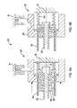
- FIG. 2A is a schematic illustration of an embodiment of a dog type clutch in a disengaged position
- FIG. 2B is a schematic illustration of the dog type clutch of FIG. 2A in an engaged position
- FIG. 3A is a schematic illustration of another embodiment of a dog type clutch in a disengaged position
- FIG. 3B is a schematic illustration of the dog type clutch of FIG. 3A in an engaged position
- FIG. 4A is a schematic illustration of a multi-plate type clutch in a disengaged position
- FIG. 4B is a schematic illustration of the multi-plate type clutch of FIG. 5A in an engaged position.
- FIGS. 1 through 4 wherein like reference numerals correspond to like or similar elements throughout the figures, various embodiments of the invention are depicted.
- FIG. 1 shows a schematic illustration of a powertrain system 10 for propelling a vehicle (not shown).
- the powertrain system 10 includes a motor 12 for generating a torque output and a transmission 14 for transmitting the torque output to the left half-shaft 16 and/or right half-shaft 18 of the vehicle.
- the transmission 14 includes a planetary gear set 19 and a clutch assembly 20 for selectively transmitting torque generated by the motor 12 to the differential 22 , which distributes the torque to the half-shafts 16 , 18 .
- the motor 12 is depicted as an electric motor 12 , it should be appreciated that the motor 12 may be an internal combustion engine, a turbine, or other torque generating devices without departing from the scope of the present disclosure.
- the transmission 14 may be a manual or automatic transmission where a finite number of gear ratios are provided through the selections of gear sets or a continuous variable transmission where continuous effective gear ratios are provided through the coordination of variable diameter pulleys without departing from the scope of the present disclosure.
- the torque generated by the motor 12 is transmitted by an output shaft 21 extending along a central axis A to the planetary gear set 19 in the transmission 16 .
- the clutch assembly 20 selectively holds a reactionary member of the planetary gear set 19 stationary to allow for the transmittal of torque through the transmission 14 .
- the planetary gear set 19 includes a plurality of planet gears 24 intermeshed between a sun gear 26 and a ring gear 28 .
- the plurality of planet gears 24 are supported by a planet carrier 29 defining a hub 30 .
- the sun gear 26 is coaxially continuously connected with the output shaft 21 of the motor 12 and the hub 30 is connected to a transfer gear 32 .
- the ring gear 28 is the reactionary member that may be selectively held stationary by the clutch assembly 20 .
- the transfer gear 32 may be engaged with additional torque transfer members or gear sets (not shown) within the transmission 14 . For the simplicity of illustration and disclosure, the transfer gear 32 is shown continuously engaged with the differential 22 .
- the clutch assembly 20 includes a hydraulically actuated clutch 34 and a latching device 36 .
- the hydraulically actuated clutch 34 shown in FIG. 2 is a dog clutch 34 having a rotatable first clutch member 38 connected to the reactionary ring gear 28 and a non-rotatable second clutch member 40 connected to a stationary component of the transmission 14 .
- FIG. 2A shows the dog clutch 34 in a disengaged state where the second clutch member 40 is disengaged from the first clutch member 38 , thereby allowing the reactionary ring gear 28 to rotate freely.
- FIG. 2B shows the dog clutch 34 in an engaged state where the second clutch member 40 is engaged to the first clutch member 38 , thereby preventing the rotation of the first clutch member 38 , resulting in the holding of the reactionary ring gear 28 stationary.
- the first clutch member 38 is rotatable about a central axis B and includes an attachment end 42 connected to the reactionary ring gear 28 of the planetary gear set 19 .
- the second clutch member 40 include an attachment end 44 slidably engaged to a spline 46 that is fixably connected, or grounded, to a stationary component of the transmission 48 , such as the transmission housing 48 .
- the second clutch member 40 is not rotatable; however, the second clutch member 40 is slidably movable in a first axial direction on the spline 46 to engage the first clutch member 38 and in a second axial direction to disengage from the first clutch member 38 .
- the non-rotatable second clutch member 40 prevents the first clutch member 38 from rotating about the central axis B.
- the first clutch member 38 includes an engagement end 50 defining a first dog gear 50 having a plurality of crowns 50 A and recesses 50 B between the crowns.
- the second clutch member 40 includes an engagement end 52 defining a second dog gear 52 having plurality of crowns 52 A and recesses 52 B complementary to the crowns 50 A and recesses 50 B of the first dog gear 50 .
- the first and second dog gears 50 , 52 are configured such that the first dog gear 50 locks onto the second dog gear 52 upon engagement, thereby solidly connecting the first clutch member 38 to the second clutch member 40 .
- the dog clutch includes at least one spring 54 having a first end 54 A in contact with the second clutch member 40 and a second end 54 B in contact with a stationary component of the transmission 14 .
- the spring 54 continuously biases the second clutch member 40 in the first axial direction to engage the first clutch member 38 .
- a hydraulically actuated piston 56 is provided to selectively move the second clutch member 40 in the second axial direction to disengage from the first clutch member 38 when sufficient hydraulic pressure is provided to the hydraulic piston 56 to overcome the biasing force of the spring 54 .
- the hydraulic pressure may be reduced or eliminated to allow the biasing force of the spring 54 to urge the second clutch member 40 to engage the first clutch member 38 .
- Hydraulic pressure may be provided by a 12V hydraulic fluid pump 58 , powered by the vehicle's battery or generator (not shown), by pumping hydraulic fluid from an onboard reservoir 60 into the hydraulic piston 56 .
- the dog clutch 34 fails in the engaged position (Shown in FIG. 2B ) due to the loss of hydraulic pressure. This may cause damage to transmission 14 during high spin conditions.
- the latching device 36 is provided in the clutch assembly 20 to retain the hydraulically actuated piston 56 in a predetermined position.
- An external surface 62 of the hydraulic piston 56 defines a recess 64 or slot 64 .
- a locking pin 66 is inserted into the slot 64 , thereby locking the hydraulic piston 56 into position.
- the locking pin 66 extends from the electrically operated latching device 36 , which is connected to a stationary component of the transmission 14 , such as the transmission housing 48 .
- the latching device 36 includes a housing 68 having a solenoid 70 and a metallic plunger 72 disposed within a coil of the solenoid 70 .
- the metallic plunger 72 includes an end defining the locking pin 66 .
- the metallic plunger 72 is axially slidably with respect to the housing 68 in an extended position and a retracted position.
- a biasing member 74 is disposed in the housing 68 to urge the metallic plunger 72 in an extended position, such that the pin 66 protrudes from the latching device housing 68 .
- An electric current may be sent through the coil of the solenoid 70 , thereby energizing the coil, to induce a magnetic force to retract the metallic plunger 72 into the housing 68 overcoming the biasing force of the spring or biasing member 74 .
- the hydraulic piston 56 is free to move axially, but subject to the balancing of forces between the hydraulic pressure acting against the piston 56 and the biasing member 74 .
- the locking plunger 72 may be further retracted into the housing 68 such that the plunger 72 does not drag on the surface 62 of the hydraulic piston 56 as the hydraulic piston 56 moves back into position.
- FIG. 3 shows an alternative embodiment of the dog clutch of FIG. 2 .
- FIG. 3A shows the dog clutch 134 in a non-engaged state where the second clutch member 140 is axially spaced from the first clutch member 138 ; thereby allowing the ring gear 28 to freely rotate and no torque is outputted by the planetary gear set 19 .
- FIG. 3B shows the dog clutch 134 in an engaged state; thereby holding the ring gear 28 stationary and allowing the torque to flow from the motor 12 through the differential 22 .
- the spring 154 of the clutch 234 of FIG. 3 continuously biases the second clutch member 140 in the second axial direction to dis-engage the second clutch member 140 from the first clutch member 138 .
- the hydraulically actuated piston 156 is provided to selectively move the second clutch member 140 in the first axial direction to engage from the first clutch member 138 when sufficient hydraulic pressure is provided to the hydraulic piston 156 to overcome the biasing force of the spring 154 .
- the hydraulic pressure may be reduced or eliminated to allow the biasing force of the spring 154 to urge the second clutch member 140 to disengage from the first clutch member 138 .
- the hydraulically actuated clutch 34 is shown in FIG. 4 as a multi-plate type clutch 234 having a rotatable first clutch member 238 connected to the ring gear 28 of the planetary gear assembly and a non-rotatable second clutch member 240 connected to the transmission housing 48 .
- a first set of clutch plates 280 extends from the first clutch member 38 and second set of clutch plates 282 extends from the second clutch member 240 . Plates from the first set of plates 280 are axially interspersed between plates from the second set of plates 282 .
- the biasing spring 254 urges the second clutch plates 282 in the first axial direction against the first clutch plates 280 ; thereby fixably coupling the second clutch member 240 to the first clutch member 238 and preventing the rotation of the first clutch member 238 .
- the piston 256 selectively moves the second clutch plates in the second axial direction, thereby overcoming the biasing of the spring 254 such that the second plates 282 are disengaged from first clutch plates 280 and allowing the rotation of the first clutch member 238 .
Landscapes
- Engineering & Computer Science (AREA)
- General Engineering & Computer Science (AREA)
- Mechanical Engineering (AREA)
- Hydraulic Clutches, Magnetic Clutches, Fluid Clutches, And Fluid Joints (AREA)
- Retarders (AREA)
- Mechanical Operated Clutches (AREA)
Priority Applications (3)
| Application Number | Priority Date | Filing Date | Title |
|---|---|---|---|
| US15/214,041 US10167906B2 (en) | 2016-07-19 | 2016-07-19 | Clutch assembly having a hydraulically actuate piston and latching device |
| CN201710541078.8A CN107631022B (zh) | 2016-07-19 | 2017-07-05 | 具有液压致动活塞和锁紧装置的离合器组件 |
| DE102017116200.3A DE102017116200B4 (de) | 2016-07-19 | 2017-07-18 | Kupplungsanordnung mit einem hydraulisch betätigten Kolben und einer Verriegelungsvorrichtung |
Applications Claiming Priority (1)
| Application Number | Priority Date | Filing Date | Title |
|---|---|---|---|
| US15/214,041 US10167906B2 (en) | 2016-07-19 | 2016-07-19 | Clutch assembly having a hydraulically actuate piston and latching device |
Publications (2)
| Publication Number | Publication Date |
|---|---|
| US20180023635A1 US20180023635A1 (en) | 2018-01-25 |
| US10167906B2 true US10167906B2 (en) | 2019-01-01 |
Family
ID=60889927
Family Applications (1)
| Application Number | Title | Priority Date | Filing Date |
|---|---|---|---|
| US15/214,041 Active 2037-02-28 US10167906B2 (en) | 2016-07-19 | 2016-07-19 | Clutch assembly having a hydraulically actuate piston and latching device |
Country Status (3)
| Country | Link |
|---|---|
| US (1) | US10167906B2 (de) |
| CN (1) | CN107631022B (de) |
| DE (1) | DE102017116200B4 (de) |
Cited By (6)
| Publication number | Priority date | Publication date | Assignee | Title |
|---|---|---|---|---|
| US11131374B2 (en) * | 2016-11-30 | 2021-09-28 | Dana Automotive Systems Group, Llc | Drive unit assembly with power boost and torque vectoring |
| US20220372730A1 (en) * | 2021-05-20 | 2022-11-24 | Deere & Company | Work vehicle multi-speed drive assembly with guided dog clutch |
| US11624170B2 (en) | 2021-02-25 | 2023-04-11 | Deere & Company | Work vehicle multi-speed drive assembly with clutch retention mechanism |
| US11686374B2 (en) | 2021-07-23 | 2023-06-27 | Deere & Company | Work vehicle multi-speed drive assembly providing multiple gear ratios at same step ratio |
| US11719209B2 (en) | 2021-03-29 | 2023-08-08 | Deere & Company | Integrated starter-generator device with unidirectional clutch actuation utilizing biased lever assembly |
| US11866910B2 (en) | 2021-02-25 | 2024-01-09 | Deere & Company | Work vehicle multi-speed drive assembly with output control clutch |
Families Citing this family (10)
| Publication number | Priority date | Publication date | Assignee | Title |
|---|---|---|---|---|
| CN107667231B (zh) * | 2015-06-03 | 2019-11-22 | 博格华纳瑞典公司 | 液压耦合器 |
| CN109070725B (zh) * | 2016-04-22 | 2022-01-28 | 美国轮轴制造公司 | 利用存储的能量移动致动器输出构件的传动系统致动器 |
| DE102017205396A1 (de) * | 2017-03-30 | 2018-10-04 | Magna powertrain gmbh & co kg | Verteilergetriebe |
| CN108916261B (zh) * | 2018-07-16 | 2019-08-27 | 武汉理工大学 | 一种牙嵌式液压离合器 |
| CN112032095B (zh) * | 2020-08-25 | 2022-04-05 | 瑞卡斯(南京)精密机械有限公司 | 一种组合式循环水泵传动轴及水泵循环方法 |
| US11680610B2 (en) * | 2021-02-11 | 2023-06-20 | Means Industries, Inc. | Clutch assembly having normally on strut configured to prevent shock load deployment |
| US11976693B2 (en) * | 2021-06-15 | 2024-05-07 | Means Industries, Inc. | Clutch assembly for coupling and decoupling clutch members |
| DE102021207134A1 (de) | 2021-07-07 | 2023-01-12 | Zf Friedrichshafen Ag | Drehmomentübertragungsvorrichtung zur Übertragung eines Drehmoments von einer Eingangswelle auf eine koaxial zu der Eingangswelle angeordneten Ausgangswelle |
| DE102021208327A1 (de) * | 2021-08-02 | 2023-02-02 | Zf Friedrichshafen Ag | Kopplungseinrichtung für ein Differential eines Kraftfahrzeugs |
| US11837423B2 (en) * | 2021-10-05 | 2023-12-05 | GM Global Technology Operations LLC | Arrangement and module for electrical contactor assemblies |
Citations (13)
| Publication number | Priority date | Publication date | Assignee | Title |
|---|---|---|---|---|
| US5048656A (en) * | 1990-08-29 | 1991-09-17 | Eaton Corporation | Fluid operated clutch control system having latch member |
| US6948685B2 (en) | 2003-10-27 | 2005-09-27 | Hr Textron, Inc. | Locking device with solenoid release pin |
| US20060040782A1 (en) | 2004-08-19 | 2006-02-23 | Diemer John J | Main shaft dog clutch and method |
| US20080264746A1 (en) * | 2005-10-17 | 2008-10-30 | Ricardo Uk Ltd | Latching Linear Actuator |
| US20080314711A1 (en) * | 2007-06-20 | 2008-12-25 | Luk Lamellen Und Kupplungsbau Beteiligungs Kg | Clutch and brake latch mechanism |
| US7891261B2 (en) | 2007-08-16 | 2011-02-22 | GM Global Technology Operations LLC | Clutch actuation system with locking mechanism and method of controlling engagement of a clutch |
| US8109376B2 (en) * | 2007-05-23 | 2012-02-07 | Zf Friedrichshafen Ag | Device for operating a shifting element of a drive mechanism |
| US20120138412A1 (en) * | 2010-12-01 | 2012-06-07 | Zf Friedrichshafen Ag | Control device of a rotating shifting element of an automatic transmission for engine start-stop operation |
| US8460144B2 (en) | 2009-06-04 | 2013-06-11 | ZF Friedrichshafen , AG | Arrangement comprising at least one dog clutch |
| US20150068344A1 (en) * | 2013-09-12 | 2015-03-12 | Zf Friedrichshafen Ag | Claw shifting element comprising a sliding sleeve for an automatic transmission of a motor vehicle |
| WO2015145241A1 (en) | 2014-03-25 | 2015-10-01 | Toyota Jidosha Kabushiki Kaisha | Transfer for four-wheel drive vehicle |
| US20170002815A1 (en) * | 2013-12-19 | 2017-01-05 | Pierburg Pump Technology Gmbh | Motor vehicle vacuum pump having a switchable clutch |
| US20170182886A1 (en) * | 2015-12-26 | 2017-06-29 | Toyota Jidosha Kabushiki Kaisha | Control system for vehicle, and control method for vehicle |
Family Cites Families (4)
| Publication number | Priority date | Publication date | Assignee | Title |
|---|---|---|---|---|
| US4697680A (en) * | 1986-06-05 | 1987-10-06 | Sundstrand Corporation | Fluid operated disconnect coupling |
| DE102009024779A1 (de) * | 2009-06-10 | 2010-12-16 | Daimler Ag | Getriebevorrichtung |
| JP5050039B2 (ja) * | 2009-11-27 | 2012-10-17 | 本田技研工業株式会社 | 油圧クラッチ装置 |
| US9157528B2 (en) * | 2012-10-15 | 2015-10-13 | GM Global Technology Operations LLC | Brake mechanism for a hybrid transmission |
-
2016
- 2016-07-19 US US15/214,041 patent/US10167906B2/en active Active
-
2017
- 2017-07-05 CN CN201710541078.8A patent/CN107631022B/zh active Active
- 2017-07-18 DE DE102017116200.3A patent/DE102017116200B4/de active Active
Patent Citations (13)
| Publication number | Priority date | Publication date | Assignee | Title |
|---|---|---|---|---|
| US5048656A (en) * | 1990-08-29 | 1991-09-17 | Eaton Corporation | Fluid operated clutch control system having latch member |
| US6948685B2 (en) | 2003-10-27 | 2005-09-27 | Hr Textron, Inc. | Locking device with solenoid release pin |
| US20060040782A1 (en) | 2004-08-19 | 2006-02-23 | Diemer John J | Main shaft dog clutch and method |
| US20080264746A1 (en) * | 2005-10-17 | 2008-10-30 | Ricardo Uk Ltd | Latching Linear Actuator |
| US8109376B2 (en) * | 2007-05-23 | 2012-02-07 | Zf Friedrichshafen Ag | Device for operating a shifting element of a drive mechanism |
| US20080314711A1 (en) * | 2007-06-20 | 2008-12-25 | Luk Lamellen Und Kupplungsbau Beteiligungs Kg | Clutch and brake latch mechanism |
| US7891261B2 (en) | 2007-08-16 | 2011-02-22 | GM Global Technology Operations LLC | Clutch actuation system with locking mechanism and method of controlling engagement of a clutch |
| US8460144B2 (en) | 2009-06-04 | 2013-06-11 | ZF Friedrichshafen , AG | Arrangement comprising at least one dog clutch |
| US20120138412A1 (en) * | 2010-12-01 | 2012-06-07 | Zf Friedrichshafen Ag | Control device of a rotating shifting element of an automatic transmission for engine start-stop operation |
| US20150068344A1 (en) * | 2013-09-12 | 2015-03-12 | Zf Friedrichshafen Ag | Claw shifting element comprising a sliding sleeve for an automatic transmission of a motor vehicle |
| US20170002815A1 (en) * | 2013-12-19 | 2017-01-05 | Pierburg Pump Technology Gmbh | Motor vehicle vacuum pump having a switchable clutch |
| WO2015145241A1 (en) | 2014-03-25 | 2015-10-01 | Toyota Jidosha Kabushiki Kaisha | Transfer for four-wheel drive vehicle |
| US20170182886A1 (en) * | 2015-12-26 | 2017-06-29 | Toyota Jidosha Kabushiki Kaisha | Control system for vehicle, and control method for vehicle |
Cited By (7)
| Publication number | Priority date | Publication date | Assignee | Title |
|---|---|---|---|---|
| US11131374B2 (en) * | 2016-11-30 | 2021-09-28 | Dana Automotive Systems Group, Llc | Drive unit assembly with power boost and torque vectoring |
| US11624170B2 (en) | 2021-02-25 | 2023-04-11 | Deere & Company | Work vehicle multi-speed drive assembly with clutch retention mechanism |
| US11866910B2 (en) | 2021-02-25 | 2024-01-09 | Deere & Company | Work vehicle multi-speed drive assembly with output control clutch |
| US11719209B2 (en) | 2021-03-29 | 2023-08-08 | Deere & Company | Integrated starter-generator device with unidirectional clutch actuation utilizing biased lever assembly |
| US20220372730A1 (en) * | 2021-05-20 | 2022-11-24 | Deere & Company | Work vehicle multi-speed drive assembly with guided dog clutch |
| US11761515B2 (en) * | 2021-05-20 | 2023-09-19 | Deere & Company | Work vehicle multi-speed drive assembly with guided dog clutch |
| US11686374B2 (en) | 2021-07-23 | 2023-06-27 | Deere & Company | Work vehicle multi-speed drive assembly providing multiple gear ratios at same step ratio |
Also Published As
| Publication number | Publication date |
|---|---|
| DE102017116200A1 (de) | 2018-01-25 |
| DE102017116200B4 (de) | 2019-10-17 |
| CN107631022A (zh) | 2018-01-26 |
| US20180023635A1 (en) | 2018-01-25 |
| CN107631022B (zh) | 2019-08-06 |
Similar Documents
| Publication | Publication Date | Title |
|---|---|---|
| US10167906B2 (en) | Clutch assembly having a hydraulically actuate piston and latching device | |
| US9777818B2 (en) | Two-speed drive module | |
| KR101563389B1 (ko) | 전기 구동 2단-변속 트랜스액슬 | |
| EP3828437B1 (de) | Mehrganggetriebe und damit hergestellte antriebsachse | |
| US9951851B2 (en) | Multi ratio drive | |
| EP3105075B1 (de) | Kupplungsanordnung und antriebsstranganordnung mit einer derartigen kupplungsanordnung | |
| US10323693B2 (en) | Disconnect system for an axle | |
| CN102083648A (zh) | 电动液压差速器锁 | |
| US10563704B2 (en) | Locking transfer case | |
| US10604008B2 (en) | Transfer case having a manually-operated four wheel drive locking mechanism | |
| WO1995020730A1 (en) | Two-speed planetary transmission having nested independently | |
| US20170158052A1 (en) | Transfer case having a four wheel drive locking mechanism | |
| EP3885177B1 (de) | Antriebsachsensystem | |
| US20190120358A1 (en) | Drive Unit For Shifting A Torque Balance | |
| US10363814B2 (en) | Transfer case with oil distribution | |
| US10766349B2 (en) | Hybrid transfer case | |
| CN107848413B (zh) | 由同步事件提供动力的传动系统致动器 | |
| US9593773B1 (en) | Vehicle gear shifter | |
| US10711893B2 (en) | Brake for unintended neutral mode in transfer case | |
| US10766362B2 (en) | Locking transfer case | |
| US11506246B2 (en) | Power transmission device |
Legal Events
| Date | Code | Title | Description |
|---|---|---|---|
| AS | Assignment |
Owner name: GM GLOBAL TECHNOLOGY OPERATIONS LLC, MICHIGAN Free format text: ASSIGNMENT OF ASSIGNORS INTEREST;ASSIGNORS:NEELAKANTAN, VIJAY A.;LITTLEFIELD, JOSEPH R.;KAMINSKY, LAWRENCE A.;SIGNING DATES FROM 20160719 TO 20160720;REEL/FRAME:039357/0604 |
|
| STCF | Information on status: patent grant |
Free format text: PATENTED CASE |
|
| MAFP | Maintenance fee payment |
Free format text: PAYMENT OF MAINTENANCE FEE, 4TH YEAR, LARGE ENTITY (ORIGINAL EVENT CODE: M1551); ENTITY STATUS OF PATENT OWNER: LARGE ENTITY Year of fee payment: 4 |