US10153675B2 - Electrical machine - Google Patents
Electrical machine Download PDFInfo
- Publication number
- US10153675B2 US10153675B2 US15/035,910 US201415035910A US10153675B2 US 10153675 B2 US10153675 B2 US 10153675B2 US 201415035910 A US201415035910 A US 201415035910A US 10153675 B2 US10153675 B2 US 10153675B2
- Authority
- US
- United States
- Prior art keywords
- stator
- phase winding
- phase
- layer
- electrical machine
- Prior art date
- Legal status (The legal status is an assumption and is not a legal conclusion. Google has not performed a legal analysis and makes no representation as to the accuracy of the status listed.)
- Active, expires
Links
Images


Classifications
-
- H—ELECTRICITY
- H02—GENERATION; CONVERSION OR DISTRIBUTION OF ELECTRIC POWER
- H02K—DYNAMO-ELECTRIC MACHINES
- H02K3/00—Details of windings
- H02K3/04—Windings characterised by the conductor shape, form or construction, e.g. with bar conductors
- H02K3/28—Layout of windings or of connections between windings
-
- H—ELECTRICITY
- H02—GENERATION; CONVERSION OR DISTRIBUTION OF ELECTRIC POWER
- H02K—DYNAMO-ELECTRIC MACHINES
- H02K1/00—Details of the magnetic circuit
- H02K1/06—Details of the magnetic circuit characterised by the shape, form or construction
- H02K1/12—Stationary parts of the magnetic circuit
- H02K1/16—Stator cores with slots for windings
- H02K1/165—Shape, form or location of the slots
-
- H—ELECTRICITY
- H02—GENERATION; CONVERSION OR DISTRIBUTION OF ELECTRIC POWER
- H02K—DYNAMO-ELECTRIC MACHINES
- H02K3/00—Details of windings
- H02K3/02—Windings characterised by the conductor material
-
- H—ELECTRICITY
- H02—GENERATION; CONVERSION OR DISTRIBUTION OF ELECTRIC POWER
- H02K—DYNAMO-ELECTRIC MACHINES
- H02K3/00—Details of windings
- H02K3/04—Windings characterised by the conductor shape, form or construction, e.g. with bar conductors
- H02K3/12—Windings characterised by the conductor shape, form or construction, e.g. with bar conductors arranged in slots
- H02K3/14—Windings characterised by the conductor shape, form or construction, e.g. with bar conductors arranged in slots with transposed conductors, e.g. twisted conductors
-
- H—ELECTRICITY
- H02—GENERATION; CONVERSION OR DISTRIBUTION OF ELECTRIC POWER
- H02K—DYNAMO-ELECTRIC MACHINES
- H02K3/00—Details of windings
- H02K3/30—Windings characterised by the insulating material
Definitions
- the invention relates to a stator for an electrical machine, comprising a stator block and at least one first and one second phase winding, wherein the first and the second phase windings are supplied with current having different phases, and comprising at least one stator slot, which is arranged in the stator block, wherein in the stator slot, several layers of the first and several layers of the second phase winding are arranged.
- the invention further relates to an electrical machine with such a stator.
- the invention relates to a stator for an electrical machine, for instance, an electric motor.
- the electrical machine is running multiphase.
- the stator comprises a stator block, which is provided with several phase windings, which are each applied with current of different phases.
- the phase windings are provided in one or several stator slots in the stator block.
- stator block often has irregularities, at whose peaks, the field is locally concentrated.
- the demands on the insulation of the stator winding against the stator block are therefore correspondingly high.
- a relatively thick electrical insulation between the stator winding and the stator must be provided in order to shield the peak field strengths.
- electrical insulators are also poor heat conductors. That is, the electrical insulation around the stator winding also forms a poor heat-conducting insulation layer. This is problematic, when large currents in the stator winding flow and relatively large heat loss outputs have to be discharged.
- a copper wire with varnish insulation is used for the phase winding of the stator, for instance.
- Several layers of the copper wire are arranged side by side and one above the other in a stator slot.
- the varnish thereby insulates adjacent layers of the copper wire against each other.
- the varnish insulation is often insufficient to insulate the copper wire against the stator block. For this reason, it is known that an additional plastic insulation layer or paper insulation layer is provided between the copper wire and the stator block.
- the proximity effect plays an essential role between adjacent conductors.
- the proximity effect is due to the magnetic flux leakage between the conductors.
- the current is pushed to the surface of the conductor, thereby reducing the effective conductor cross section.
- the electrical resistance load per unit length of the conductor is thereby increased in a disadvantageous way.
- varnish insulation for instance, is only stable up to temperatures of approximately 200° C.
- additional plastic insulation or paper insulation has a relatively low thermal conductance value. That is, the heat produced in the phase winding is only poorly discharged by the stator block.
- stator in which the proximity effect is significantly reduced.
- the object of the invention is to increase the degree of filling of the stator, that is, to fill a larger cross section of the stator slot with electrically conductive material.
- a further object is to reduce the stray magnetic field of the stator block.
- phase winding with a good thermal conductance value shall be provided.
- the heat produced in the interior of the phase winding shall be released well to the stator block.
- a further object is to provide a stator with a phase winding which is easier to produce.
- Another object is to develop a stator which allows improved heat dissipation over the stator block.
- a stator for an electrical machine comprising a stator block and at least one first and one second phase winding, wherein the first and the second phase windings are supplied with current having different phases, and wherein at least one stator slot is arranged in the stator block, wherein in the stator slot, several layers of the first and several layers of the second phase winding are arranged, and which is characterized in that in the stator slot, a layer of the first phase winding adjoins a layer of the second phase winding.
- the stator according to the invention is used in a multi-phase electrical machine, an electric motor or a generator.
- multi-phase means that at least two currents of different phases are applied to the electrical machine. Accordingly, at least one first phase winding and one second phase winding are provided, through which a first and a second current of different phases are flowing. It may also be useful to provide further phase windings, which are either supplied with the first current, the second current or one or several additional currents of a different phase.
- the stator has a stator block, in which at least one stator slot is provided.
- the stator slot is used to receive the phase windings or a part of the phase windings.
- the stator slot runs preferably circular or circular-segmented around the axis, around which the rotor of the electrical machine rotates.
- the stator slot has an expansion in axial direction (depth of the stator slot), an expansion in radial direction (width of the stator slot) as well as a length expansion, which is extending circular or circular-segmented around the rotation axis.
- the alignments “radial” and “axial”, respectively, here relate to the rotation axis, around which the rotor of an electrical machine with a stator according to the invention would rotate.
- the phase windings or individual conduction elements, from which the phase windings are arranged, are stapled in several layers into the stator slot.
- layer here denotes a certain plane vertically to the axial direction.
- conduction elements of the first phase winding as well as conduction elements of the second phase winding are brought in the same stator slot.
- the individual conduction elements of the two phase windings are provided such that conduction elements lying one above the other belong to different phase windings, that is, a layer of the first phase winding adjoins a layer of the second phase winding.
- the invention allows the usage of other conductor profiles than thin wires.
- the cross section of a phase winding respectively a layer of a phase winding can be varied within wide limits and can be adapted to the shape of the stator slot, for instance. It is no longer mandatory to use thin wires or thin strands. Also rectangular profiles such as ribbon-shaped conductors can be used, which have not been used until now because of the negative effects of the proximity effect.
- All layers of the first and of the second phase winding are advantageously arranged such that no layer of the first phase winding adjoins another layer of the first phase winding. Only layers of different phase windings adjoin each other. Since currents of a different phase flow through the different phase windings, the proximity effect is prevented and the entire cross section of a phase winding is used for the current flow. An increase of the electric resistance respectively of the resistance load per unit length of the phase winding by the proximity effect is avoided.
- the first and/or second phase winding are each preferably made of several conductor elements, which are electrically connected to each other, and then form the respective phase winding.
- the first and/or the second phase winding or parts respectively conductor elements of the first and/or the second phase winding are advantageously formed of a metal sheet and/or ribbon-shaped.
- the metal sheet or the ribbon is of a good electrically conducting material, normally of a metal, particularly of copper or aluminum.
- This embodiment has the advantage compared to a phase winding with the round cross section, to say compared to a common wire, that the cross section of the metal sheet or the ribbon can be adapted to the cross section of the stator slot.
- the width of the ribbon can be provided corresponding to the width of the stator slot, so that one layer of the phase winding fills exactly the width of the stator slot. This way, the degree of filling, to say the cross section relation of electrically conducting material to the total cross section of the stator slot, can be significantly increased.
- stator slot in the context of a series production is difficult to achieve.
- the production of the stator is considerably easier.
- phase windings are preferably produced from anodized aluminum.
- the aluminum is oxidized, and thus gets an electrically insulation layer of aluminum oxide on its surface. It is of advantage to use metal sheets or ribbon-shaped elements of anodized aluminum for the phase windings.
- the ribbon-shaped conductor elements can also be produced by flattening a pipe or a similar profile.
- the pipe or profile can be bent in the desired shape and flattened by means of a tool. Compared to punching out, this has the advantage that the edges are not sharp, but round. When anodizing, there is the risk that the oxidic protection layer is not forming or not forming sufficiently enough at sharp edges. This is prevented by the curves formed by the flattening.
- the electrical connection of the individual conductor elements and the individual layers of a phase winding is done outside of the stator slot. This is done by bringing out the conductor elements, metal sheets, ribbons or ribbon-shaped elements from the stator slot and to provide them with a connector. It is only necessary then to connect these connectors with each other.
- the aluminum oxide layer provides in many cases a sufficient electrical insulation so that an additional insulation between the individual aluminum elements, aluminum metal sheets, or aluminum ribbons is not necessary.
- stator slots are preferably arranged staggered in radial direction.
- a phase winding is inserted into the stator slot such that inside a stator slot, the current flow is running through all conductor elements of the same phase winding in the same direction.
- the current flow through the conductor elements inserted into the other stator slot of the same phase winding is, however, oppositely parallel aligned. This way, the outward stray field of the conductor elements of the phase winding inserted into the one stator slot is compensated by the conductor elements of the same phase winding inserted into the other stator slot.
- the stator block partly comprises ridges, peaks and a surface roughness.
- the aluminum oxide layer also has a relatively rough surface. At such inhomogeneities, high electric field strengths can occur. Should the electrical insulation not be sufficient, for instance, because the anodized layer cannot be produced thick enough on the aluminum metal sheets, it is of advantage to provide the stator block such that said stator block has at least in defined areas, particularly in the areas adjoining the stator slot, a specific electrical resistance in the range of a semiconductor, for instance, between 10 4 ohm mm 2 /m and 10 8 ohm mm 2 /m. These in fact relatively high-resistance, but yet to some extent conducting areas of the stator block are used to homogenize the electrical field in the area of the stator slot and particularly in the insulation of the phase winding so that the field peaks are smoothed.
- the high-resistance area of the stator block has a resistance of more than 50 kohm (50.000 ⁇ ), more than 100 kohm, more than 200 kohm or more than 500 kohm.
- this high-resistance area has a value of less than 10 megaohm, less than 5 megaohm or less than 1 megaohm (1.000.000 ⁇ ).
- the stator block or areas of the stator block are made of a casting compound or a composite mixture, which has a high-resistance resistance per unit length.
- a casting compound or a composite mixture is used, for instance, which is, however, electrically conductive, but has a high-resistance resistance load per unit length.
- the resistance load per unit length to say the electrical resistance per length unit, is preferably at least two or three ranges higher than the resistance load per unit length of the phase winding.
- resin, silicone or a plastic comes into question, which are mixed with electrically conductive elements of, for instance, graphite or aluminum oxide.
- the stator block is preferably made of soft magnetic material (Soft Magnetic Composite—SMC). This allows a cost-effective production of complex stator geometries with very low eddy current losses and isotropic, magnetic characteristics.
- SMC Soft Magnetic Composite
- the invention is suitable for electric motors as well as generators and particularly electrical machines designed as transverse flux machine.
- the transverse flux machine is understood as electrical machine, at which the magnetic flux in the stator is primarily moving in one plane, which lies vertically to the moving direction or rotation alignment of the runner or rotor.
- the invention is particularly suitable for axial transverse flux machines, at which the magnetic flux passes basically through the air gap between stator and rotor in axial direction—in contrast to radial transverse flux machines, at which the magnetic flux passes basically through the air gap between stator and rotor in radial direction.
- a phase winding comprises several conductor elements in the stator slot, wherein one or several conductor elements are arranged planar and form one layer. That is, the conductor element/s is/are aligned in a plane, particularly in a plane vertically to the rotation axis of the rotor of the electrical machine.
- the individual layers are connected to each other outside the stator slot such that these are connected in series and form a phase winding.
- the individual layers of the phase winding are lying parallel to each other and parallel to the rotational plane of the rotor. Neither the conductor elements of the same phase winding nor the conductor elements of different phase windings cross each other in the stator slots.
- the invention also relates to an electrical machine with a stator as claimed.
- the invention brings particular advantages for electrical machines, electric motors or generators, which have a rotor and particularly exactly one rotor.
- the invention provides an electrical machine with constant torque. It is not necessary to mechanically couple several one-phased machines in order to generate a constant torque. The problems connected to a mechanical coupling are thereby avoided.
- stator In a two-phased electrical machine, two phase windings are provided, which are applied with a current offset in the phase by 90°.
- the stator for instance, comprises four stator blocks with a pair of stator slots, respectively, wherein each pair of stator slots has a radial inner and a radial outer stator slot running parallel to each other.
- both phase windings are arranged such that within a stator slot, no layers of the same phase winding border on each other and that within a layer, to each conductor element of a phase winding in the outer stator slot, a corresponding conductor element of the same phase winding in the inner stator slot is provided, wherein the current flow through the conductor element in the inner stator slot runs opposite to the current flow in the outer stator slot.
- the first phase winding for instance, is applied with a current +I1 and the second phase winding with an alternating current +I2 offset in the phase by 90°.
- both phase windings are supplied with current of the combinations +I1, ⁇ I2 as well as ⁇ I1, +I2 and ⁇ I1, ⁇ I2. This way, a best possible homogenization of the torque can be reached.
- the invention is not limited to two-phased electrical machines.
- the concept according to the invention can be expanded to three- and multi-phased machines accordingly.
- the stator may comprise several stator sectors with, for instance, four stator blocks each.
- the individual stator blocks are provided as mentioned above.
- a first and a second phase winding are provided, which are phase-shifted supplied with current.
- the phase windings of different stator sectors also have a phase shift to each other.
- the invention has numerous advantages in contrast to the known concepts. Despite the use of phase windings with a large cross section, the proximity effect is greatly reduced.
- the individual layers of a phase winding can be arranged planar so that each layer runs in a plane parallel to the rotational plane of the rotor. Within the stator slot, no “plane shift” is required.
- the phase windings are easily and quickly produced since each phase winding can be formed modularly from several uniform conductor elements.
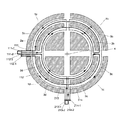
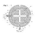
- FIG. 1 the winding scheme of a stator according to the invention
- FIG. 2 a conductor element, from which the two phase windings are composed
- FIG. 3 the arrangement of the layers of the two phase windings in the stator block 1 a of FIG. 1 ,
- FIG. 4 the arrangement of the layers of the two phase windings in the stator block 1 b of FIG. 1 ,
- FIG. 5 the resulting magnetomotive force vector in the stator block 1 a
- FIG. 6 the resulting magnetomotive force vector in the stator block 1 b.
- FIG. 1 the stator of a two-phased electric motor is schematically shown.
- the stator comprises four stator blocks 1 a, 1 b, 1 c, 1 d, which are each quarter-circular.
- Each stator block 1 a, 1 b, 1 c, 1 d is provided with an inner stator slot 2 a, 2 b, 2 c, 2 d and an outer stator slot 3 a, 3 b, 3 c, 3 d, respectively.
- the stator slots 2 a, 2 b, 2 c, 2 d, 3 a, 3 b, 3 c, 3 d are provided parallel to each other and are also circularly provided around the rotation axis 4 of the rotor not shown for reasons of clarity.
- stator slots 2 a, 2 b, 2 c, 2 d, 3 a, 3 b, 3 c, 3 d several layers of a first and of a second phase winding are inserted.
- the first and the second phase winding are composed of conductor elements 5 as shown in FIG. 2 .
- a conductor element 5 is made of anodized aluminum sheet and is of two semi-circular arches 6 , 7 , whose shape and size are adapted to the inner and to the outer stator slot 2 a, 2 b, 2 c, 2 d, 3 a, 3 b, 3 c, 3 d.
- the inner arch 6 and the outer arch 7 are connected with each other at one of their ends by a connecting piece 8 .
- connection elements 9 , 10 are provided at the other ends of the arches 6 , 7 .
- the entire conductor element 5 comprising the arches 6 , 7 , the connecting piece 8 and the connection elements 9 , 10 may be produced, for instance, from punching out from an aluminum sheet.
- the conductor elements 5 are adapted planar into the stator slots 2 a, 2 b, 2 c, 2 d, 3 a, 3 b, 3 c, 3 d.
- the conductor elements 5 are formed such that they cover the entire width of the stator slots 2 a, 2 b, 2 c, 2 d, 3 a, 3 b, 3 c, 3 d in radial direction.
- a first conductor element 111 is inserted into the stator slots 2 a, 2 b, 3 b, 3 a and a second conductor element 112 is inserted into the stator slots 2 d, 2 c, 3 c, 3 d.
- the two conductor elements 111 , 112 are oriented such that their connection elements 111 - 1 , 111 - 2 , 112 - 1 , 112 - 2 come to lie in the area of the gap between the two stator blocks 1 a, 1 d.
- the two conductor elements 111 , 112 form a first layer 101 of the first phase winding. This first layer 101 lies planar in a plane in the stator slots 2 a, 2 b, 2 c, 2 d, 3 a, 3 b, 3 c, 3 d.
- two conductor elements 211 , 212 are placed on the conductor elements 111 , 112 .
- the conductor elements 213 , 214 are thereby rotated by 90° against the conductor elements 111 , 112 , to say conductor element 213 is provided in the stator slots 2 d, 2 a, 3 a, 3 d and conductor element 214 is accordingly provided in the stator slots 2 c, 2 b, 3 b, 3 c.
- the connection elements 213 - 1 , 213 - 2 , 214 - 1 , 214 - 2 are again arranged side by side.
- the two conductor elements 213 , 214 form a first layer 201 of the second phase winding.
- a second layer 102 of the first phase winding is applied on this first layer 201 of the second phase winding.
- the second layer 102 of the first phase winding is identical with the first layer 101 of the first phase winding.
- a second layer 202 of the second phase winding is then placed. This way, several layers of the first and the second phase winding are alternately placed one above the other (see FIGS. 3, 4 ). All layers belonging to the same phase winding are hereby provided identically.
- connection elements 11 - 1 , 12 - 1 respectively 13 - 1 , 14 - 1 of the conductor elements belonging to one phase winding are arranged side by side respectively one above the other outside of the stator slot 2 a, 2 b, 2 c, 2 d, 3 a, 3 b, 3 c, 3 d.
- the connection elements 11 - 1 , 12 - 1 respectively 13 - 1 , 14 - 1 are connected by connecting bridges 15 , 16 such that all conductor elements belonging to one phase winding are connected in series and form the desired phase winding.
- FIG. 3 shows the arrangement of the layers 101 , 201 , 102 , 202 of the first and the second phase winding in the inner stator slot 2 a and the outer stator slot 3 a of the stator block 1 a.
- a corresponding arrangement is shown in FIG. 4 for the stator block 1 b.
- FIG. 5 schematically shows the current feed of the two phase windings and, as a result, the magnetomotive force vector 17 in the stator block 1 a.
- a current I A sin wt shall flow through the first phase winding and a current I B cos wt shall flow through the second phase winding. That is, the two phase windings are applied with alternating currents phase-shifted by 90°.
- stator blocks 1 a, 1 b, 1 c, 1 d Corresponding considerations can be made for all stator blocks 1 a, 1 b, 1 c, 1 d. It appears that the resulting magnetomotive force vectors 17 a, 17 b, 17 c, 17 d are phase-shifted by 90° between each other, respectively.
- FIG. 6 shows this again as an example for the stator block 1 b.
- phase shift of the resulting magnetomotive force vectors 17 a, 17 b, 17 c, 17 d in the individual stator blocks 1 a, 1 b, 1 c, 1 d it is ensured that overall a uniform torque is generated.
Landscapes
- Engineering & Computer Science (AREA)
- Power Engineering (AREA)
- Windings For Motors And Generators (AREA)
Applications Claiming Priority (4)
| Application Number | Priority Date | Filing Date | Title |
|---|---|---|---|
| EP13005299 | 2013-11-11 | ||
| EP13005299.6 | 2013-11-11 | ||
| EP13005299.6A EP2871753B1 (de) | 2013-11-11 | 2013-11-11 | Elektrische Maschine |
| PCT/EP2014/003001 WO2015067371A1 (de) | 2013-11-11 | 2014-11-10 | Elektrische maschine |
Publications (2)
| Publication Number | Publication Date |
|---|---|
| US20160276891A1 US20160276891A1 (en) | 2016-09-22 |
| US10153675B2 true US10153675B2 (en) | 2018-12-11 |
Family
ID=49578071
Family Applications (1)
| Application Number | Title | Priority Date | Filing Date |
|---|---|---|---|
| US15/035,910 Active 2035-08-19 US10153675B2 (en) | 2013-11-11 | 2014-11-10 | Electrical machine |
Country Status (4)
| Country | Link |
|---|---|
| US (1) | US10153675B2 (ja) |
| EP (1) | EP2871753B1 (ja) |
| JP (1) | JP6602759B2 (ja) |
| WO (1) | WO2015067371A1 (ja) |
Citations (13)
| Publication number | Priority date | Publication date | Assignee | Title |
|---|---|---|---|---|
| JPS5594554A (en) | 1979-01-10 | 1980-07-18 | Hitachi Ltd | Lead wire device of three-phase ac rotary machine |
| US5906909A (en) * | 1997-01-06 | 1999-05-25 | Presstek, Inc. | Wet lithographic printing constructions incorporating metallic inorganic layers |
| US6163097A (en) * | 1996-12-11 | 2000-12-19 | Smith Technologies Development, Llc | Motor generator including interconnected stators and stator laminations |
| US20030164656A1 (en) * | 2002-03-01 | 2003-09-04 | Denso Corporation | Stator of vehicle AC generator |
| US20050093393A1 (en) * | 2003-11-03 | 2005-05-05 | Hirzel Andrew D. | Stator coil arrangement for an axial airgap electric device including low-loss materials |
| US20050134135A1 (en) * | 2003-12-17 | 2005-06-23 | Myers Timothy M. | Stator coil assembly |
| US20060022552A1 (en) * | 2004-07-28 | 2006-02-02 | Silicon Valley Micro M Corporation | Multi-phase A.C. vehicle motor |
| US20060220488A1 (en) * | 2005-03-30 | 2006-10-05 | Denso Corporation | Rotary electric machine and stator coil for rotary electric machines |
| US20070138895A1 (en) * | 2005-12-21 | 2007-06-21 | Delair Charles M | Maximum conductor motor and method of making same |
| EP2255431A1 (de) | 2008-03-15 | 2010-12-01 | Rainer Marquardt | Trägheitsarmer direktantrieb grosser leistungsdichte |
| US20100321664A1 (en) * | 2009-06-19 | 2010-12-23 | Asml Netherlands B.V. | Coil, positioning device, actuator, and lithographic apparatus |
| US20140339938A1 (en) * | 2013-03-13 | 2014-11-20 | Honeywell International Inc. | Gas turbine engine actuation systems including high temperature actuators and methods for the manufacture thereof |
| US20160126794A1 (en) * | 2014-09-16 | 2016-05-05 | Greentech Motors Corporation | Electric Motor With Laminated Sheet Windings |
Family Cites Families (10)
| Publication number | Priority date | Publication date | Assignee | Title |
|---|---|---|---|---|
| NL163075C (nl) * | 1976-07-12 | 1980-07-15 | Gils Adrianus Van | Gelamineerde wikkeling voor elektrische machines. |
| JPS5537511U (ja) * | 1978-08-31 | 1980-03-11 | ||
| JPS60181150U (ja) * | 1984-05-08 | 1985-12-02 | 株式会社三協精機製作所 | 多層プリントコイルを有する回転検出装置 |
| JP3857846B2 (ja) * | 1999-12-03 | 2006-12-13 | 三洋電機株式会社 | コンデンサ電動機 |
| JP2002095226A (ja) * | 2000-07-14 | 2002-03-29 | Asmo Co Ltd | 回転電動機の製造方法 |
| JP2002153001A (ja) * | 2000-11-09 | 2002-05-24 | Mitsubishi Electric Corp | 回転電機の固定子 |
| JP2006296001A (ja) * | 2005-04-06 | 2006-10-26 | Inp Institute Of Technology Co Ltd | 回転電機および電磁機器 |
| JP2009296745A (ja) * | 2008-06-04 | 2009-12-17 | Panasonic Corp | 多極アキシャルギャップ型コンデンサ電動機とその製造方法 |
| JP5691266B2 (ja) * | 2010-07-01 | 2015-04-01 | トヨタ自動車株式会社 | 回転電機固定子 |
| WO2012137306A1 (ja) * | 2011-04-05 | 2012-10-11 | トヨタ自動車株式会社 | ステータ及びステータ製造方法 |
-
2013
- 2013-11-11 EP EP13005299.6A patent/EP2871753B1/de not_active Not-in-force
-
2014
- 2014-11-10 JP JP2016529940A patent/JP6602759B2/ja active Active
- 2014-11-10 WO PCT/EP2014/003001 patent/WO2015067371A1/de active Application Filing
- 2014-11-10 US US15/035,910 patent/US10153675B2/en active Active
Patent Citations (14)
| Publication number | Priority date | Publication date | Assignee | Title |
|---|---|---|---|---|
| JPS5594554A (en) | 1979-01-10 | 1980-07-18 | Hitachi Ltd | Lead wire device of three-phase ac rotary machine |
| US6163097A (en) * | 1996-12-11 | 2000-12-19 | Smith Technologies Development, Llc | Motor generator including interconnected stators and stator laminations |
| US5906909A (en) * | 1997-01-06 | 1999-05-25 | Presstek, Inc. | Wet lithographic printing constructions incorporating metallic inorganic layers |
| US20030164656A1 (en) * | 2002-03-01 | 2003-09-04 | Denso Corporation | Stator of vehicle AC generator |
| US20050093393A1 (en) * | 2003-11-03 | 2005-05-05 | Hirzel Andrew D. | Stator coil arrangement for an axial airgap electric device including low-loss materials |
| US20050134135A1 (en) * | 2003-12-17 | 2005-06-23 | Myers Timothy M. | Stator coil assembly |
| US20060022552A1 (en) * | 2004-07-28 | 2006-02-02 | Silicon Valley Micro M Corporation | Multi-phase A.C. vehicle motor |
| US20060220488A1 (en) * | 2005-03-30 | 2006-10-05 | Denso Corporation | Rotary electric machine and stator coil for rotary electric machines |
| US20070138895A1 (en) * | 2005-12-21 | 2007-06-21 | Delair Charles M | Maximum conductor motor and method of making same |
| EP2255431A1 (de) | 2008-03-15 | 2010-12-01 | Rainer Marquardt | Trägheitsarmer direktantrieb grosser leistungsdichte |
| US20110057532A1 (en) * | 2008-03-15 | 2011-03-10 | Rainer Marquardt | Low-Inertia Direct Drive Having High Power Density |
| US20100321664A1 (en) * | 2009-06-19 | 2010-12-23 | Asml Netherlands B.V. | Coil, positioning device, actuator, and lithographic apparatus |
| US20140339938A1 (en) * | 2013-03-13 | 2014-11-20 | Honeywell International Inc. | Gas turbine engine actuation systems including high temperature actuators and methods for the manufacture thereof |
| US20160126794A1 (en) * | 2014-09-16 | 2016-05-05 | Greentech Motors Corporation | Electric Motor With Laminated Sheet Windings |
Also Published As
| Publication number | Publication date |
|---|---|
| JP2016536961A (ja) | 2016-11-24 |
| EP2871753B1 (de) | 2019-06-19 |
| EP2871753A1 (de) | 2015-05-13 |
| US20160276891A1 (en) | 2016-09-22 |
| JP6602759B2 (ja) | 2019-11-06 |
| WO2015067371A1 (de) | 2015-05-14 |
Similar Documents
| Publication | Publication Date | Title |
|---|---|---|
| KR102476984B1 (ko) | 코팅 도체가 적층된 고정자 조립체 | |
| US6806612B2 (en) | Armature coil for slotless rotary electric machinery | |
| US20200091786A1 (en) | Electric motor with laminated sheet windings | |
| US10910897B2 (en) | Water-cooled generator strip having a cooling channel gap space | |
| EP2086090A1 (en) | Coil assembly for electrical rotating machine, stator for electrical rotating machine, and electrical rotating machine | |
| US20200403462A1 (en) | Common Lamination Component for Accommodating Multiple Conductor Geometries in an Electric Machine | |
| US20120146447A1 (en) | Stator for rotary electrical machine | |
| TW202037037A (zh) | 定子及電動機 | |
| US11605993B2 (en) | Rotary motors incorporating flexible printed circuit boards | |
| US20140077648A1 (en) | Electric winding for electric energy converters or machines, method for manufacturing same and electric machine | |
| KR20160112959A (ko) | 전기 기기용 권선 | |
| BR112021014731A2 (pt) | Máquina elétrica de fluxo axial e componentes auxiliares | |
| EP1100179A1 (en) | Winding for a motor or a generator | |
| US9819238B2 (en) | Rotary electric machine having stator with coil conductors having different cross-sectional width | |
| BR112021014769A2 (pt) | Máquina elétrica de fluxo axial | |
| CN109861430A (zh) | 流体冷却且流体绝缘的电机 | |
| US2788456A (en) | Conductor-ventilated generators | |
| US20230112188A1 (en) | Windings for electrical machines | |
| US10153675B2 (en) | Electrical machine | |
| Moros et al. | Geometrical and electrical optimization of stator slots in electrical machines with combined wye-delta winding | |
| WO2020037968A1 (zh) | 绕组定子及电动机 | |
| JP5341621B2 (ja) | 回転電機 | |
| JP2005176463A (ja) | モータ | |
| JP2024024492A (ja) | モータ | |
| JP2022178242A (ja) | ステータ及びモータ |
Legal Events
| Date | Code | Title | Description |
|---|---|---|---|
| AS | Assignment |
Owner name: LEANTEC MOTOR GMBH, GERMANY Free format text: ASSIGNMENT OF ASSIGNORS INTEREST;ASSIGNORS:MUELLER, UDO;HEIN, SOEREN;SIGNING DATES FROM 20160502 TO 20160715;REEL/FRAME:039163/0526 |
|
| STCF | Information on status: patent grant |
Free format text: PATENTED CASE |
|
| MAFP | Maintenance fee payment |
Free format text: PAYMENT OF MAINTENANCE FEE, 4TH YR, SMALL ENTITY (ORIGINAL EVENT CODE: M2551); ENTITY STATUS OF PATENT OWNER: SMALL ENTITY Year of fee payment: 4 |