US10127521B2 - System and method for determining and controlling status and location of an object - Google Patents
System and method for determining and controlling status and location of an object Download PDFInfo
- Publication number
- US10127521B2 US10127521B2 US15/457,592 US201715457592A US10127521B2 US 10127521 B2 US10127521 B2 US 10127521B2 US 201715457592 A US201715457592 A US 201715457592A US 10127521 B2 US10127521 B2 US 10127521B2
- Authority
- US
- United States
- Prior art keywords
- asset
- mobile vehicle
- central control
- status
- location
- Prior art date
- Legal status (The legal status is an assumption and is not a legal conclusion. Google has not performed a legal analysis and makes no representation as to the accuracy of the status listed.)
- Active
Links
Images


Classifications
-
- G—PHYSICS
- G06—COMPUTING; CALCULATING OR COUNTING
- G06Q—INFORMATION AND COMMUNICATION TECHNOLOGY [ICT] SPECIALLY ADAPTED FOR ADMINISTRATIVE, COMMERCIAL, FINANCIAL, MANAGERIAL OR SUPERVISORY PURPOSES; SYSTEMS OR METHODS SPECIALLY ADAPTED FOR ADMINISTRATIVE, COMMERCIAL, FINANCIAL, MANAGERIAL OR SUPERVISORY PURPOSES, NOT OTHERWISE PROVIDED FOR
- G06Q10/00—Administration; Management
- G06Q10/08—Logistics, e.g. warehousing, loading or distribution; Inventory or stock management
- G06Q10/087—Inventory or stock management, e.g. order filling, procurement or balancing against orders
-
- B—PERFORMING OPERATIONS; TRANSPORTING
- B65—CONVEYING; PACKING; STORING; HANDLING THIN OR FILAMENTARY MATERIAL
- B65G—TRANSPORT OR STORAGE DEVICES, e.g. CONVEYORS FOR LOADING OR TIPPING, SHOP CONVEYOR SYSTEMS OR PNEUMATIC TUBE CONVEYORS
- B65G43/00—Control devices, e.g. for safety, warning or fault-correcting
-
- G—PHYSICS
- G05—CONTROLLING; REGULATING
- G05B—CONTROL OR REGULATING SYSTEMS IN GENERAL; FUNCTIONAL ELEMENTS OF SUCH SYSTEMS; MONITORING OR TESTING ARRANGEMENTS FOR SUCH SYSTEMS OR ELEMENTS
- G05B15/00—Systems controlled by a computer
- G05B15/02—Systems controlled by a computer electric
-
- G—PHYSICS
- G06—COMPUTING; CALCULATING OR COUNTING
- G06K—GRAPHICAL DATA READING; PRESENTATION OF DATA; RECORD CARRIERS; HANDLING RECORD CARRIERS
- G06K7/00—Methods or arrangements for sensing record carriers, e.g. for reading patterns
- G06K7/10—Methods or arrangements for sensing record carriers, e.g. for reading patterns by electromagnetic radiation, e.g. optical sensing; by corpuscular radiation
- G06K7/10009—Methods or arrangements for sensing record carriers, e.g. for reading patterns by electromagnetic radiation, e.g. optical sensing; by corpuscular radiation sensing by radiation using wavelengths larger than 0.1 mm, e.g. radio-waves or microwaves
- G06K7/10366—Methods or arrangements for sensing record carriers, e.g. for reading patterns by electromagnetic radiation, e.g. optical sensing; by corpuscular radiation sensing by radiation using wavelengths larger than 0.1 mm, e.g. radio-waves or microwaves the interrogation device being adapted for miscellaneous applications
-
- G—PHYSICS
- G06—COMPUTING; CALCULATING OR COUNTING
- G06K—GRAPHICAL DATA READING; PRESENTATION OF DATA; RECORD CARRIERS; HANDLING RECORD CARRIERS
- G06K7/00—Methods or arrangements for sensing record carriers, e.g. for reading patterns
- G06K7/10—Methods or arrangements for sensing record carriers, e.g. for reading patterns by electromagnetic radiation, e.g. optical sensing; by corpuscular radiation
- G06K7/14—Methods or arrangements for sensing record carriers, e.g. for reading patterns by electromagnetic radiation, e.g. optical sensing; by corpuscular radiation using light without selection of wavelength, e.g. sensing reflected white light
- G06K7/1404—Methods for optical code recognition
- G06K7/1408—Methods for optical code recognition the method being specifically adapted for the type of code
- G06K7/1413—1D bar codes
-
- G—PHYSICS
- G06—COMPUTING; CALCULATING OR COUNTING
- G06K—GRAPHICAL DATA READING; PRESENTATION OF DATA; RECORD CARRIERS; HANDLING RECORD CARRIERS
- G06K7/00—Methods or arrangements for sensing record carriers, e.g. for reading patterns
- G06K7/10—Methods or arrangements for sensing record carriers, e.g. for reading patterns by electromagnetic radiation, e.g. optical sensing; by corpuscular radiation
- G06K7/14—Methods or arrangements for sensing record carriers, e.g. for reading patterns by electromagnetic radiation, e.g. optical sensing; by corpuscular radiation using light without selection of wavelength, e.g. sensing reflected white light
- G06K7/1404—Methods for optical code recognition
- G06K7/1408—Methods for optical code recognition the method being specifically adapted for the type of code
- G06K7/1417—2D bar codes
Definitions
- This invention relates generally to the field of automated data collection. More specifically, this innovation relates to determining and controlling a location and status of an asset, directly or indirectly.
- Position-tracking systems seek to identify the location of mobile objects in real-time and are used in a wide variety of applications, including transportation, logistics management, healthcare, security, etc. Position-tracking systems that can provide continuous location information are desirable for applications that require non-interrupted visibility of the mobile object through a journey.
- U.S. Pat. No. 7,321,305 discusses a system and method for determining the location of an object.
- the system includes an object location tracker and a corresponding computer system.
- the object location tracker is configured for attachment to a mobile vehicle and includes an object identification reading device and a position-tracking device.
- the object identification reading device senses object identification indicia on the object, such as radio frequency identification (RFID) tags, bar codes, quick response (QR) codes, etc. as the mobile vehicle moves around an environment in which the object is situated.
- RFID radio frequency identification
- QR quick response
- the computer system associates the sensed object identification indicia of the object, as determined by the reading device, with a location in the environment based on the position of the object location tracker in the environment, as determined by the position tracking device, when the reading device senses the object identification indicia.
- the mobile vehicle may include its own mobility system, such as for example, a forklift or an autonomous robotic device, a drone, or the mobile vehicle may be, for example, a pushcart that is pushed around the environment.
- the technique uses an active object location tracker on a mobile vehicle, which then is used to locate a multitude of other assets that carry passive indicia.
- Techniques are described with regard to determining and controlling a location and status of assets directly and/or indirectly.
- the techniques may be used to track and control the respective locations and status of any number of objects.
- Applications include but are not limited to tracking dry and refrigerated trailers and their status in a supply-chain yard; tracking pallets and boxes and their status in a warehouse; tracking items in a retail environment; tracking finished goods and work in progress in and around a manufacturing plant; tracking vehicles in a parking lot; tracking cargo and equipment at an airport; tracking equipment in a lay down yard; etc.
- the laborious and error prone data gathering is replaced with automated data collection methods reducing cost, increasing accuracy, and increasing efficiency.
- FIG. 1 is a schematic diagram that shows high level components of the system and method, according to an embodiment
- FIG. 2 is a schematic diagram that shows some details of the installed on asset equipment, according to an embodiment
- FIG. 3 is a schematic diagram that shows some details of the installed on vehicle equipment, according to an embodiment
- FIG. 4 is a schematic diagram that shows some details the interaction between an IoA and an IoV, according to an embodiment
- FIG. 5 is a schematic diagram that shows some details concerning the central control entity and a plurality of facilities, according to an embodiment
- FIG. 6 is a schematic diagram showing segments of a mobile vehicle trajectory where the installed on vehicle equipment is in-range with installed on asset equipment;
- FIG. 7 is a schematic diagram showing how in-range segments of a mobile vehicle trajectory can be used to determine actual asset location
- FIG. 8 is a block schematic diagram of a system in the exemplary form of a computer system according to an embodiment.
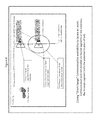
- FIG. 1 is a schematic diagram that shows high level components of an embodiment: in a facility (C 1 ) one or more mobile vehicles (C 3 ) equipped with installed on vehicle (“IoV”) equipment (C 3 . 1 ) move around along various trajectories (C 6 ) to track the location and status of various assets (C 2 ) equipped with installed on asset (“IoA”) equipment (C 2 . 1 ), where IoV communicates with the central control (C 5 ) either directly via (C 8 .X with direct Internet access) or indirectly via (C 8 . 1 a local network) through communication medium (C 4 in the facility) and then (C 8 . 2 a direct Internet connection).
- IoV vehicle
- C 5 central control
- C 5 either directly via (C 8 .X with direct Internet access) or indirectly via (C 8 . 1 a local network) through communication medium (C 4 in the facility) and then (C 8 . 2 a direct Internet connection).
- Facility (C 1 ), in FIG. 1 can be any one of but not limited to a distribution center, manufacturing plant, warehouse, retail store, lay down yard, construction site, farm, or airport.
- These facilities contain assets (C 2 ) whose location need to be tracked such as but not limited to trailers, pallets, equipment, and cargo. Additional information about their status can be collected, such information including but not limited to temperature of a refrigeration unit, fuel/power level of any powered device, maintenance needs of any equipment, condition of any product, etc. Such assets may or may not have the ability to communicate this status. In the case that an asset can communicate its status, such communication may have limited range or may require tethering to the asset.
- Such facilities contain mobile vehicles (C 3 ) that can move about the facility a) as part of the regular operation; b) with the specific intent of moving the assets; or c) with the specific intent of gathering location and status information.
- These vehicles can be any one of but not limited to a yard truck, a forklift, a push cart, a drone, a tractor, a boat, or even a person on foot.
- a central control system (C 5 ) is an IT system that
- the technique For assets in the facility to be able to communicate with central control the technique needs a communication mechanism.
- the communication mechanism provides coverage, such that assets are either wired to the channel or are wirelessly in-range of communication.
- “Broad-range” communication such as that implemented by cellular carriers or satellite providers, essentially allows one to connect to Internet anywhere inside or outside the facility (assuming coverage).
- Direct connectivity to Internet allows connectivity to central control.
- the IoV equipment may use such communication (C 8 .X) to communicate with central control.
- Broad range communication typically carries a service fee to third parties and requires significant power consumption (e.g. cell phone batteries are drained within hours if connected to Internet via cellular networks) as the communication range is to an antenna miles away.
- the IoV equipment may leverage the vehicle battery as power supply, however, for passive assets the IoA cannot rely on a battery for extended periods of time.
- “Facility-range” communication can be implemented by installing a system such as WiMax or multiple WiFi access points. In this case the coverage is available in almost all of the facility, and one can leverage such wireless coverage (C 8 . 1 ) to connect to the communication medium of the facility which may then use for example a wired DSL a Cable connection (C 8 . 2 ) to connect to the Internet.
- a system such as WiMax or multiple WiFi access points.
- the coverage is available in almost all of the facility, and one can leverage such wireless coverage (C 8 . 1 ) to connect to the communication medium of the facility which may then use for example a wired DSL a Cable connection (C 8 . 2 ) to connect to the Internet.
- This scheme can reduce the third party costs as cellular or satellite connectivity is more expensive than a DSL or Cable connection. Conversely one has to maintain its own WiMax or WiFi system. However, even in this system power consumption can be an issue. It is commonly known that most WiFi connected devices deplete their power within hours. One still has to transmit a signal that has to travel 10-100 meters. The IoV equipment may use this scheme to connect to central control, as the battery in the vehicle can power the equipment.
- “Local-range” communication is meant for immediate vicinity of up to about 10 meters.
- the transmission range is reduced the power consumption for communication is reduced as well. While such communication is ideal for devices that do not have their own power source or ample battery power, it can provide a challenge in providing coverage for all devices in the facility. This challenge can be overcome in three ways:
- An important goal is to communicate with a central control system (C 5 ) for proper operation of the facility with exact knowledge of the location and status of the assets in the facility. It is assumed that in the facility there is a communication medium (C 4 ) which can act as a gateway between facility (C 1 ) and its contents, e.g. assets and mobile vehicles, on one end and central control (C 5 ) on the other end. Such communication is assumed to provide coverage in the facility (facility range as defined above).
- the IoV equipment can leverage the facility range coverage (C 8 . 1 ) via (C 4 ) and (C 8 . 2 ) to central control, or it can use broad coverage (C 8 .X) to connect to Internet directly.
- Central control (C 5 ) is responsible for collecting the relevant data; analyzing and processing the collected data; interacting with other information technology (“IT”) systems ( FIG. 5 , C 9 ); interacting with human operators ( FIG. 5 , C 12 ); creating actionable instructions; and communicating the actionable instructions back to mobile vehicle (C 3 ) and assets (C 2 ). Examples of such instructions are provided below.
- IT information technology
- IoA C 2 . 1
- FIG. 2 An embodiment of IoA (C 2 . 1 ) is depicted in greater detail in FIG. 2 and is comprised of any of or any combination of:
- An asset may or may not come pre-equipped with one or more built in sensors having interfaces (C 2 . 0 . 1 ) and one or more actuators having interfaces (C 2 . 0 . 2 ).
- IoV IoV
- the IoA equipment may consist of an indicium, it may consist of multiple indicia, and it may have indicia and one or more sensors or actuators.
- IoA equipment C 2 . 1
- IoA equipment is not required to have broad or facility range communication capabilities and may be limited to local (short) range communication, thus keeping the IoA costs down, ensuring long battery life, and minimizing third party communication fees.
- such short range communication can be implemented without any power source (like an RFID or a BarCode id) and has lower cost (currently, the cost of BarCode is sub-pennies and the cost of RFID is pennies or 10s of cents).
- the communication approach provided in embodiments herein obviates the need to plaster the facility with communication equipment or to depend on complex or costly mesh networks. It implements the locationing, tracking, and control actions with lower cost, lower power devices leveraging the third scheme.
- mobile vehicle sensors use a plurality of technologies to gather state information. Examples of such technology include but are not limited to:
- An interaction between IoA and IoV can be understood with reference to FIG. 4 .
- Asset indicia reader (C 3 . 1 . 2 ) on the vehicle uses asset indicia (C 2 . 1 . 1 ) on each of the assets to identify the asset, depicted as interaction referred to as identify (C 7 . 1 ).
- Local sensors (C 3 . 1 . 4 ) on vehicle (C 3 ) externally sense the status of asset (C 2 . 1 ), while sensor interface (C 3 . 1 . 5 ) communicates with sensory equipment, external sensor (C 2 . 1 . 2 ) and asset sensor/actuator gateway (C 2 . 1 . 3 ), on asset (C 2 . 1 ). This interaction is depicted as sense (C 7 . 2 ).
- sensed information are obtained either by external sensors or through interaction with native sensors.
- sensed information can include but are not limited to:
- Actuator interface (C 3 . 1 . 6 ) on vehicle (C 3 ) transmits control commands (C 7 . 3 ) to actuator gateway on the asset sensor/actuator gateway (C 2 . 1 . 3 ). This interaction is depicted as control.
- IoV also acts as an interface (C 10 ) for human operators (C 12 ) to central control (C 5 ) to receive instructions or input data to the system.
- the IoA can use direct (broad range) or indirect (facility range) communication to interact with central control.
- such interaction can be implemented via local range communication where connection to (C 4 ) is available in select and limited spots in the facility.
- connection to (C 4 ) is available in select and limited spots in the facility.
- the mobile vehicle traverses trajectories (C 6 ) such communication becomes possible on limited segments.
- the mobile vehicle interacts with (C 5 ) while in-range, it transmits collected information and receives future commands; otherwise it is in data-gathering and command transmitting mode.
- IoA equipment C 2 . 1
- IoA equipment does not have facility communication range.
- One indicia reader in the Facility may not have the ability to read all indicia of IoA equipment. Read ranges of 1-10 or even 100 meter make it infeasible to plaster the facility with readers such that any given indicium is in the range of at least one reader. Therefore understanding the movement of vehicle (C 3 ) can be important because as a vehicle (C 3 ) follows a trajectory, such as for example trajectory (C 4 ) depicted in FIG. 1 , vehicle (C 3 ) gets in and out of communication range of such detection and communication.
- mobile vehicle (C 3 ) can be a gateway between asset (C 2 ) and the rest of the world via central control (C 5 ) and other IT systems (C 9 )—i.e. the IoA and IoV can use local range communication, the IoV then leverages facility or broad communication range to further relay the communication.
- the points of the trajectory where such communication is possible or is not possible with asset (C 2 ) are used to locate the asset (C 2 ).
- the triangles C 2 . 1 . x depict the communication range of the IoA sensors.
- This segment combined with the known communication range pattern of the IoV equipment limits the possible locations of said sensor and hence asset to a shape (depicted as ellipse E 1 ) in the facility. The intersections of such ellipses then limit the possible location of an Asset.
- Each mobile vehicle (C 3 ) processes and transmits its collected data to central control (C 5 ) directly (C 8 . x ) or indirectly through (C 8 . 1 ) via communication medium through (C 8 . 2 ) to (C 4 ).
- Central control (C 5 ) then processes such information and transmits back instructions to the mobile vehicles (C 3 ).
- Such bi-directional communication interactions are depicted in FIG. 1 .
- Central control (C 5 ) collates information coming from the various mobile vehicles (C 3 ) and creates a current image of the facility using the collated information. For example as a vehicle moves along a trajectory, as in FIG. 7 , it collects information from in-range sensors 10 times a second. Since the IoV equipment includes GPS, the IoV Computer (C 3 . 1 . 1 ) can connect each GPS point on its trajectory with a set of in-range interactions. It has the ability to convert this information to segments of trajectory a given sensor was in-range. It transmits this data stream to Central Control for further processing.
- Central Control has the ability to post-process either the raw or pre-processed data (raw data including time stamps along with GPS coordinates and in-range sensor data, whereas in one embodiment C 3 . 1 . 1 can map these to segments of the trajectory where a given sensor is in rage).
- Central Control also has the ability to create shapes such as E 1 for each segment coming from multiple vehicles. In FIG. 7 , two such trajectories and two such possible shapes that correspond to in-range trajectory segments are depicted.
- the shapes are much more restrictive as antennas on IoA and IoV are typically directional and have very specific shapes of communication range. The intersection of these shapes then indicates a potential set of locations for the asset.
- both P 3 and P 4 are possible asset locations given the two trajectories; a third trajectory or the presence of other assets may be able to further increase location accuracy.
- Central control (C 5 ) collates such points from the various vehicles and creates a time evolved set of points for which each asset is visible. This time-evolved set of points for each asset in turn allows central control (C 5 ) to determine most likely locations of that asset.
- Assets (C 2 ) with installed on asset equipment (C 2 . 1 ) are an elegant structure and provide elegant functionality, which yield low cost and do not require broad or facility range communication capability.
- a mobile vehicle (C 3 ) with its installed on vehicle equipment (C 3 . 1 ) moves along a trajectory (C 6 )
- vehicle (C 3 ) interacts with a plurality of assets (C 2 ) as each asset (C 2 ) comes into the proximity of (C 3 ) in its local range communication area.
- the information gathered by the mobile vehicle is further transmitted to central control (C 5 ) for consumption.
- Example asset location tracking techniques by leveraging communication range with assets can be found in the following co-assigned patents: U.S. Pat. No. 7,245,215 “Position-Tracking Device for Position Tracking System”; U.S. Pat. No. 7,236,091 “Position-Tracking System”; and U.S. Pat. No. 7,321,305, “Systems and Methods for Determining a Location of an Object,” each of which is incorporated herein by reference.
- Such asset location tracking techniques can be augmented and enhanced with unique sensing and control capabilities of the assets by the mobile vehicle, as described herein.
- the gateway created by the mobile vehicle between a plurality of assets having local communication range and the central control system (C 5 ) can be effected by other known means.
- many local range communication devices can communicate among themselves and ultimately communicate indirectly in facility-range (i.e. within the reach of the network) and ultimately connect to the communication medium (C 4 ).
- Such devices provided for example by Linear Technology (Headquarters, Milpitas, Calif.) or ABB (Wickliffe Ohio) add cost of complexity to assets. Examples of these solutions can be found on the Internet. Examples include Wireless Sensor Networks—Dust Networks on the Linear Technology website or Wireless networks on the ABB website.
- IoA (C 2 . 1 ) is passive and does not depend on any local energy source.
- An example of this is passive RFID Tags, which currently are also referred to as C1G2 RFID Tags.
- C1G2 RFID Tags For example, see “Specification for RFID Interface” by EPCglobal Inc. (GS1, Lawrenceville, N.J.).
- the sensors i.e. the tag implementing the indicium do not have a power source
- a reader and antenna originate a waveform, which is absorbed by the antennae on the tag, which wakes up the tag, uses the energy in the wave to respond back and transmit its content, its indicium in this case.
- C 2 . 0 . 1 or C 2 . 0 . 2 can serve as an asset indicium or an asset sensor/actuator gateway (C 2 . 1 . 3 ) can be configured to act as an asset indicium.
- Active devices with long range communication capabilities on the asset can also be used as an alternative for direct communication between IoA equipment (C 2 . 1 ) and central control (C 5 ).
- IoA equipment C 2 . 1
- central control C 5
- power consumption requirements and device cost are higher than implementing the present innovation, and such communication relies on broad communication range as defined above
- a facility (C 1 ) can contain a plethora of devices similar to that of IoV equipment (C 3 . 1 ), referred to herein as Installed on Facility Equipment (IoF) such that any asset (C 2 ) and IoA equipment (C 2 . 1 ) can be guaranteed to be within the communication range of an IoF.
- IoF Installed on Facility Equipment
- the equipment cost, equipment installation cost, and equipment maintenance cost is significantly higher than implementing the present innovation.
- the innovation includes a technique (“system”) for determining a location and status of a multitude of assets and controlling their status by leveraging a mobile vehicle.
- a technique for determining a location and status of a multitude of assets and controlling their status by leveraging a mobile vehicle.
- An important aspect of this innovation is that the assets and installed on asset equipment are kept simple and low in cost, without requiring the assets and the installed on asset equipment to have the capability of communication at long range.
- the mobile vehicle as it moves along a trajectory with its installed on vehicle equipment then interacts with one or more assets as it comes into their proximity.
- the information gathered by the mobile vehicle then is further transmitted to a central control for consumption.
- installed on asset equipment can be comprised of any of or any combination of:
- the mobile vehicle e.g. a push cart, an autonomous/ground-piloted drone, a plane, a yard truck, a truck, a go-cart, a car, a Segway, etc.
- vehicle Equipment comprising:
- a central control system ( FIG. 1 C 5 ) then receives, collates, and analyzes the information, and determines the future actions. Such future actions can be based on human or third party control systems.
- exemplary such actions may include:
- the mobile vehicle follows a trajectory ( FIG. 1 C 6 ) across the space a facility occupies.
- the on board computer C 3 . 1 . 1
- collects location information from the position tracking system C 3 . 1 . 3 ), preferably at the highest possible and necessary frequency (e.g., typically ten times per second).
- the need to sample at high frequency stems from the speed of the vehicle. If it is moving at 10 m/sec (22.37 miles per hour), if the sampling frequency is once a second, the assets that were in-range during that second may have been detected from anywhere on that 10 meter segment, if the sampling frequency is 10 times a second, the assets that were in range during that tenth of a second will have been detected from a one meter segment.
- the frequency determines the accuracy of the in-range segment of the trajectory explained above ( FIG. 7, 6.1 . 1 ), which in turn determines the locationing accuracy of the location detection algorithm since the in-range segment length determines the size of the shape ( FIG. 7 E 1 . 1 or E 1 . 2 ) of the possible locations of the asset.
- each transmitted information can be (100*128/8+100)* 1 . 5 about 2.5 Kbytes per transmission. If one were to transmit ten times a second, 24 hours a day, 30 days a month one transmits about 66 Giga Bytes of data per month. While in practice one does not transmit every hour of every day, the calculation above illustrates why one should sample as much as necessary, not to incur unwarranted communication costs. Presently, a typical cellular broadband package costs approximately $50 per 10GigaBytes per month.
- sensory data collected via (C 3 . 1 . 1 , 3 . 1 . 4 , 3 . 1 . 5 ). It should be appreciated that sensory data can be sampled at much lower frequency, as e.g. the temperature of a refrigeration unit does not change significantly within seconds.
- the local computer pre-processes such data (e.g. it can have the built in intelligence of what data has incremental value, or is sufficiently different across each sample) and transmits such collected location information and data from the indicia/sensor readers (using C 3 . 1 . 7 indirectly via 8 . 1 to C 4 via 8 . 2 or directly via 8 . x ) to central control (C 5 ).
- 8 . 1 may be implemented by WiFi
- 8 . 2 may be a DSL or cable service that provides wired connectivity to Internet and hence central control.
- 8 . x can leverage cellular or satellite communication that provides direct access to Internet and hence to central control. The same communication medium is used to interact with central control.
- a human operator may create a move request of a trailer from one location in the yard (as determined per the locationing algorithms) to a dock door for the trailer to be emptied.
- a control algorithm that has a programmed flow of trailer handling (e.g. the flow being a loaded trailer with said product needs to be emptied at dock doors 3-7; the control algorithm then using knowledge of which doors are free and determining where to move the trailer) may create the move.
- the central control system in turn collates the information coming in from multiple vehicles, along with any combination of data sources such as but not limited to a) human data input, b) other sensors, and c) status prediction models. It cleanses the data leveraging the redundancies in the information; establishes a best effort ground truth conclusion; and makes such conclusion available to other human operators or other automated control systems.
- An example of such cleansing is as follows. As a human operator moves a trailer in a distribution center yard, it may tell the central control that it has placed the trailer at parking spot 12 . Subsequently, as a yard truck passes by the area, the algorithm used to locate assets may place the trailer at parking spot 15 .
- the central control may present the information as is with both parking spots as possible locations of the trailer for users/other IT systems to determine the next steps.
- it can use the past accuracy track record for the human operator to weigh the operator's input more or less heavily compared to the automated input.
- the central control may judge that the trailer is indeed at parking spot 15 .
- decisions of what to do next are based on the deduced fact that the trailer is at parking spot 15 . It may well be that the trailer is not supposed to be parked in that area, e.g.
- the mobile vehicle may follow a trajectory ( FIG. 1 C 4 ) independent of its interaction with IoA equipment.
- the trajectory can be a random trajectory or it can be a trajectory devised for a specific purpose such as a security check round.
- the trajectory can be specifically devised to ensure a communication/interaction need for example such as identified by central control or such as a preset trajectory to cover a specific area.
- the trajectory may vary as a function of real-time information, such as but not limited to a) status information collected from IoA or b ) presence/absence of other objects in the path of the trajectory, e.g. humans on the road, cranes in the flight path of a drone etc.
- the innovation operates in one or more facilities with one or more mobile vehicles, and tracks one or more assets.
- Illustrative combinations are described as follows. Such combinations are for illustrative purposes and are not meant to be limiting.
- an external IT system selects a number of refrigerated trailers to carry outbound loads. Furthermore it provides the planned departure times of these loads and determines that the loads should be ready about an hour before departure.
- This information instructs the central control (C 5 ) to turn on the refrigeration units on these trailers to lower their temperature as determined by the load they have to carry. Assuming the loading action takes two hours, and assuming the cooling of the trailer takes two hours, and in this facility typically every part of the yard is traversed by a mobile vehicle (C 3 in this case a yard truck or a Segway that personnel, such as security, drives around on a regular basis, or a drone that has a regular flight plan to check location and status of assets) at least once an hour, transmitting the turn-on command for a trailer seven hours before the departure time would correspond to the optimal time of transmitting the turn on command.
- Central command can transmit this command to the mobile vehicles (C 3 ) in the facility either via (C 8 . 2 ) to (C 4 ) to (C 8 . 1 ) or directly via ( 8 . x ) to (C 3 ) if they are using a direct broad range communication scheme.
- the mobile vehicles (C 3 ) then as part of their operation, as they traverse trajectories (C 6 ) as they come to within the vicinity of an asset (in this case a refrigerated trailer) with their actuator interface (C 3 . 1 . 6 ) can local-range communicate with an asset sensor actuator gateway (C 2 . 1 . 3 ) on the asset that interfaces with the actuator interface of the refrigerated trailer (C 2 . 0 . 2 ) to turn on the refrigerated trailer on just in time.
- an asset sensor actuator gateway C 2 . 1 . 3
- the former represents significant installation or maintenance cost.
- the latter typically results in such action taking place typically once or twice a day for the trailers that will be loaded that day.
- Such action represents manual labor costs, is prone to error, and is not energy efficient.
- To have the assets ready “in-time” typically means that a person walks the entire yard and turns on the trailers that are needed in a given day.
- the temperature and fuel level of the reefer trailers can be checked to ensure proper conditioning.
- central control (C 5 ) may receive from the transportation management system (C 11 ) planned departure times and planned travel times.
- central control is in a position to react to such information, as follows.
- the mobile vehicle e.g. mobile vehicle (C 3 ) as part of its otherwise operations checks refrigerated trailer fuel levels using its IoV equipment (C 3 . 1 ). It can then transmit this information as described above indirectly (C 8 . 1 to C 4 to C 8 . 2 ) or directly (C 8 . x ) to central control (C 5 ).
- Central control may include a model of refrigeration units which predicts refrigeration fuel consumption. A comparison of predicted fuel levels versus actual fuel levels may reveal that fuel consumption has exceeded the predictions. Either because of model limitations or special weather conditions of the day, clearly fuel consumption can exceed the prediction.
- a business rule can then send instructions to the mobile vehicles to traverse set trajectories that ensure “local-range” vicinity to the IoA equipment in the entire facility.
- Autonomous vehicles receive and execute such commands with their on board computer (C 3 . 1 . 1 ) whereas human operators leverage (C 12 ) a console (C 11 ) to retrieve and execute the request to immediately gather to the fuel level and temperature information.
- GPS may not be as readily available a number of other techniques can be used by the position tracking device on the mobile vehicle, such as optical guidance, fixed asset markers around the building, sensor network on the ceiling, etc.
- a number of fork-lifts may be equipped with the IoV equipment and perform cycle counts on the assets (pallets, boxes, unstructured assets) on the shelves while also tracking the other equipment in the warehouse.
- the IoV can be placed on a push cart operated by customers or one of the employees and perform cycle counts on the assets (pallets, boxes, unstructured assets) on the shelves while also tracking the other equipment in the store.
- the presence and location of the assets are determined by focusing on the in-range segments (C 6 . 1 from FIG. 6 ) and applying the algorithms described above in the context of FIGS. 6 and 7 .
- location tracking is performed in 3D.
- central control C 5
- C 5 central control
- One or more embodiments obviate the need of intensive labor to perform these cycle counts or the need to have facility-range communication coverage to perform inventory checks.
- the computer system on the mobile vehicle (C 3 . 1 . 1 ) can choose to engage extended flight paths, to cover overflow and irregular parking spots.
- the instructions to the IoV (C 3 ) by central control (c 5 ) are, in addition to perform an inventory, to compare the inventory against a pre-specified list and take corrective action if there are missing assets.
- One aspect of embodiments described herein is, again, the ability to perform inventory checks and to locate assets without a facility or broad range communication mechanism on the assets.
- the benefit of this is multi fold.
- a mis-parked vehicle may not be reworked in time.
- a vehicle shipped a day early is converted to cash a day early. Plus the result is achieved with less labor cost.
- assets are primarily trailers; and assets are primarily moved by yard trucks or tractors.
- assets In a construction yard high value assets can be carried and moved by any individual.
- assets may require regular maintenance.
- movement and maintenance has to follow set protocol of checking in and checking out of assets.
- humans are not reliable.
- An autonomous vehicle such as a ground robot car or an aerial drone (C 3 ) can follow set travel or flight paths (C 6 ) to cover the construction area (C 1 ).
- the vehicle as sensor interface (C 3 . 1 . 5 ) can use near field communication (NFC) to interrogate NFC compliant assets (i.e. IoA C 2 . 01 . 1 is NFC compliant) and equipment for necessary maintenance. For example some heavy machinery may require an oil change after a certain number of operational hours.
- the vehicle can also compare actual asset location to presumed asset location based on manual check-in/check-out operation. In another embodiment such check-in/check-out can be implemented and monitored by additional sensors, such as stationary RFID readers that implement a choke-point for entry and exit.
- User input (C 12 ) may suggest that particular power drill is in one part of the facility, while the approach described herein may place it elsewhere. This may result in an alert to a supervisor.
- Determination of maintenance needs can be an escalated event that halts construction.
- the misplaced asset may be combustive material such as dynamite. Determination of misplaced assets may trigger an extended inventory check.
- the drive/flight trajectory of the mobile vehicle may have to accommodate crane movement in the construction area and sequence its trajectory components to avoid high traffic areas. In different embodiments such adjustment may be made by
- Some sensors used on the assets and vehicles may have limits on their accuracy.
- the indicia/asset-id readers may not always perform flawlessly.
- the weather conditions may further impact communication and sensor performance.
- the data they gather may be redundant or may not be always in agreement.
- the central control can analyze such data across multiple sources and determine ground truth from a superset of data.
- not all assets may be seen every time by every vehicle, but all assets are bound to be seen sometime by some vehicle.
- a given asset (C 2 ) may have limited local-range communication (C 2 . 1 . x ) depicted as a triangle.
- C 2 . 1 . x limited local-range communication
- FIG. 7 as the mobile vehicle (C 3 ) passes by on a trajectory (C 6 . 1 ) with a theoretical in-range segment of (C 6 . 1 . 1 ) may fail to communicate or detect the indicium on the Asset or interact with the sensors due to noise, occlusion, or imprecision in the system.
- the same negative conditions are unlikely to hold every subsequent trajectory's in-range segment (c 6 . 2 . 1 etc.) unless there is a total failure on the IoA equipment.
- the central control can determine that no information has been obtained from part of the facility, i.e. the trajectories (C 6 ) have not covered parts of the facility (C 1 ) in sizes that far exceed the local-range communication of IoA equipment (C 2 . 1 . x as depicted in FIG. 6 ).
- Central control (C 5 ) can then require a vehicle to follow a set trajectory in that area initially for an inventory and status check.
- a request can be sent to a human driver or an autonomous vehicle leveraging communication mechanisms indirectly (C 8 . 2 C 4 C 8 . 1 ) or directly (C 8 . x ) for the vehicle (C 3 ) to traverse a said trajectory (C 6 ) in that area.
- Data collected from this and other trajectories can be communicated to other IT systems (C 9 ).
- C 9 Data collected from this and other trajectories
- a trailer that has not left the facility as planned can become a delay notification to the transportation management system.
- they can be alerts for human operators (C 12 ) for them to call the carrier.
- central control can deduce a failure and dispatch a human operator through the human operator interface (C 12 ).
- the central control has to conclude that the asset is either no longer in the facility or its IoA has failed. If asset entry and exit to the facility is strictly controlled, this suggests an IoA failure. However, if a human operator subsequently cannot locate the asset in the facility, this suggests a failed check-out.
- a method for determining and controlling a status of an asset in a facility using a mobile vehicle comprises: reading, by an object identification device on said mobile vehicle, indicia of an asset in range; determining, by a position-tracking device on said mobile vehicle, a location of said mobile vehicle; sensing, by at least one sensor on said mobile vehicle, status of the asset; receiving, by at least one receiver on said mobile vehicle, a communication from at least one sensor on said asset; transmitting, by at least one transmitter on said mobile vehicle, a communication to at least one actuator on said asset; communicating, by a communication mechanism on said mobile vehicle, with a central control server; recording, by a computer system on said mobile vehicle, any of: said location of the mobile vehicle obtained from said position-tracking device; indicia of said asset, read by said object identification device; and said status of said asset obtained from said at least one mobile vehicle sensor; transmitting, by said computer system on said mobile vehicle, said recorded information to said central control server; receiving from said central control server, by said computer system
- the mobile vehicle is any of a car, a push cart, a person, a plane, a drone, and a Segway; wherein the mobile vehicle is propelled by a force comprising any of: an engine, a human, or an animal; and the mobile vehicle is guided by any of: autonomously, local humans, remote humans, and animals.
- the at least one mobile vehicle sensor uses a plurality of technologies to gather state information, said technology comprising: RFID; ultrasound; infrared; radar; laser; accelerometers, gyroscopes, and inertial measurement units, barometers, temperature sensors, speed and altitude detectors, and camera.
- the at least one transmitter and said at least one receiver communicate in a plurality of technologies with said at least one asset sensor to gather state information or to transmit actuation control, said technologies comprising: RF; NFC communication protocols; IOT communication protocols; Bluetooth; Zigbee; 802.11x; and UWB.
- the sensed information comprise any of: location; age; fuel level; temperature; humidity; weight; size (width, depth, height); service codes; and error codes.
- control instructions to said at least one actuator on said asset comprise any of or any combination of: turn on; turn off; adjust temperature setting; adjust communication protocol; adjust communication frequency; and clear error codes.
- a trajectory of said mobile vehicle is determined and altered in real-time due to any of or any combination of: information collected by said mobile vehicle; facility layout; recent arrival or departures or other asset movement; past age of assets in the facility; weather conditions; facility activity level; central control; and other objects entering a planned trajectory timeline.
- the position tracking device on said mobile vehicle uses one or more of the following to determine its location, speed, and heading: GPS; known asset locations in the facility, implemented by markers, from which the device triangulates its location; assisted GPS; an optical system or a PX4Flow; an altimeter or a Lidar or similar device; Inertial Measurement Units; J-Bus or CAN-bus interface of the vehicle; and ultrasonic sensors.
- the mobile vehicle communicates with said central control server over any of: cellular infrastructure; cellular infrastructure comprising any of: 3G, 4G, 5G, 1 ⁇ RTT, GPS, GSM, or CDMA; Y-max; 802.11x; mesh networks; Zigbee; and any communication technology.
- the object identification device uses any of or any combination of the following to detect and identify said asset and said indicia on said asset: C1G2, G3, UWB, active, passive, semi-active, semi-passive RFID; bar codes; QR codes; actual image and image recognition; and image insignia and insignia recognition.
- a method for determining and controlling a status of an asset in a facility comprises: sensing, by at least one sensor on said asset in the facility, a status of said asset; transmitting, by said at least one sensor on said asset, said status to a mobile device in range; interacting, via at least one sensor actuator gateway on said asset, with said at least one sensor on said asset, at least one actuator on said asset, and an external system; and receiving, at said at least one actuator on said asset, at least one control command from said mobile device in range.
- the at least one sensor on said asset uses a plurality of technologies to sense asset status, said technologies comprising: RFID; ultrasound; infrared; radar; laser; accelerometers, gyroscopes, and inertial measurement units; barometers, temperature sensors, speed and altitude detectors; and built in diagnostics and actuation systems.
- the sensed information comprise any of: location; age; fuel level; temperature; humidity; weight; size (width, depth, height); service codes; and error codes.
- the at least one control command comprises any of: turn on; turn off; adjust temperature setting; adjust communication protocol; adjust communication frequency; and clear error codes.
- a method for determining and controlling a status of an asset in a facility using a central control server comprises: receiving, at said central control server, communication from a plurality of mobile vehicles; collating and aggregating, at said central control server, information from said received communication across a predetermined time interval and a predetermined geographical range of space; based on said collated and aggregated information, determining by the central control server, the status of the asset and computing by an algorithm at said central control server used to locate positions of assets the location of the asset in the facility; based on said collated and aggregated information, generating, at said central control server, at least one actuator action for said asset; and transmitting, by said central control server, said at least one actuator action intended for said asset.
- the at least one actuator action comprises any of: turn on; turn off; adjust temperature setting; adjust communication protocol; adjust communication frequency; and clear error codes.
- the central control server further comprises: gathering and subsequently collating information gathered by additional stationary sensors; collating and aggregating information about mobile vehicle location, speed, and heading of a particular mobile vehicle of said plurality of mobile vehicles and generating a list of assets that are in range at said location; reverse engineering said information to determine where in a 3D coordinate point in the facility and when an asset having equipment is in range; and based on said information computing a most likely location of said asset at a given time; resolving inconsistent data in said collated information by identifying, weighing, and applying particular redundancies in the collated information to increase overall accuracy of said information; comparing said collated information with data entered by human operators or predicted by system models, and determining a reliability of data from each data source; comparing data between user generated asset movement information and said computed most likely asset location information and using similar data to increase location accuracy of said asset; when particular data from said data from each data source is determined to be unreliable, replacing said unreliable data with said data determined reliable; presenting current status information
- the central control server communicates with said mobile vehicle over any of: cellular infrastructure; cellular infrastructure comprising any of: 3G, 4G, 5G, 1 ⁇ RTT, GPS, GSM, or CDMA; Y-max; 802.11x; mesh networks; Zigbee; and any communication technology.
- generating said at least one actuator action further comprises using data from any of or any combination of a human source, a third party control system, and a business rule.
- FIG. 8 is a block schematic diagram of a system in the exemplary form of a computer system 800 within which a set of instructions for causing the system to perform any one of the foregoing methodologies may be executed.
- the system may comprise a network router, a network switch, a network bridge, personal digital assistant (PDA), a cellular telephone, a Web appliance or any system capable of executing a sequence of instructions that specify actions to be taken by that system.
- PDA personal digital assistant
- the computer system 800 includes a processor 802 , a main memory 804 and a static memory 806 , which communicate with each other via a bus 808 .
- the computer system 800 may further include a display unit 810 , for example, a liquid crystal display (LCD) or a cathode ray tube (CRT).
- the computer system 800 also includes an alphanumeric input device 812 , for example, a keyboard; a cursor control device 814 , for example, a mouse; a disk drive unit 816 , a signal generation device 818 , for example, a speaker, and a network interface device 828 .
- the disk drive unit 816 includes a machine-readable medium 824 on which is stored a set of executable instructions, i.e. software, 826 embodying any one, or all, of the methodologies described herein below.
- the software 826 is also shown to reside, completely or at least partially, within the main memory 804 and/or within the processor 802 .
- the software 826 may further be transmitted or received over a network 830 by means of a network interface device 828 .
- a different embodiment uses logic circuitry instead of computer-executed instructions to implement processing entities.
- this logic may be implemented by constructing an application-specific integrated circuit (ASIC) having thousands of tiny integrated transistors.
- ASIC application-specific integrated circuit
- Such an ASIC may be implemented with CMOS (complementary metal oxide semiconductor), TTL (transistor-transistor logic), VLSI (very large systems integration), or another suitable construction.
- DSP digital signal processing chip
- FPGA field programmable gate array
- PLA programmable logic array
- PLD programmable logic device
- a machine-readable medium includes any mechanism for storing or transmitting information in a form readable by a machine, e.g. a computer.
- a machine readable medium includes read-only memory (ROM); random access memory (RAM); magnetic disk storage media; optical storage media; flash memory devices; electrical, optical, acoustical or other form of propagated signals, for example, carrier waves, infrared signals, digital signals, etc.; or any other type of media suitable for storing or transmitting information.
- embodiments may include performing operations and using storage with cloud computing.
- cloud computing may mean executing algorithms on any network that is accessible by Internet-enabled or network-enabled devices, servers, or clients and that do not require complex hardware configurations, e.g. requiring cables and complex software configurations, e.g. requiring a consultant to install.
- embodiments may provide one or more cloud computing solutions that enable users, e.g. users on the go, to track and control the respective locations and statuses of an object, said tracking and controlling on such Internet-enabled or other network-enabled devices, servers, or clients.
- one or more cloud computing embodiments include track and control the respective locations and statuses of an object using mobile devices, tablets, and the like, as such devices are becoming standard consumer devices.
Abstract
Description
-
C 1. Facility -
C 2. Asset- C 2.1. Installed On Asset Equipment (IoE)
- C 2.1.1. Equipment details described below
- C 2.1. Installed On Asset Equipment (IoE)
- C 3. Vehicle
- C 3.1. Installed On Vehicle Equipment (IoV)
- C 3.1.1. Equipment details described below
- C 3.1. Installed On Vehicle Equipment (IoV)
- C 4. Communication Medium
-
C 5. Central Control -
C 6. Vehicle Trajectory -
C 7. Interaction between IoE and IoV - C 8. Direct or indirect (via communication medium) interaction between IoV equipment and Central Control
- C 9. Other IT Systems
-
C 10. Central Control Human Interface -
C 11. Other IT Systems Human Interface -
C 12. Human Operators
-
- collects information coming from the facility;
- implements business rules;
- presents the information to human operators (C 12);
- interacts with other it systems (C 9); and
- based on input from human operators, other IT systems, and its implemented business rules sends back commands to the assets in the facility.
-
- 1. Plastering or covering a facility with communication equipment (i.e. placing communication equipment within a facility), e.g. every 10 meters to create full coverage.
- 2. Implementing a complex mesh network so that communication to (C 4) can be achieved via other IoA equipment.
- 3. Moving to the vicinity of the IoA equipment with a vehicle (C 3) that is moving about in the facility.
-
- C 2.1.1 An asset indicium or indicia such as a barcode, a quick response (QR) code, a radio frequency identification (RFID), and the like;
- C 2.1.2 A set of external sensors that can sense and transmit the status of the asset; and
- C 2.1.3 A sensor/actuator gateway that can interact with the native sensors and actuators on the asset and also bi-directionally communicate with the IoV equipment.
-
- C 3.1.1 A local computer that is in communication with the entities listed below and that performs various functionality, described in greater detail below;
- C 3.1.2 An indicia reader system which may be a camera, an RFID reader and antenna, or any other system;
- C 3.1.3 A location detector which is used to determine a precise location of the vehicle. For example, location detector 3.1.3 may be GPS, differential GPS, GPS augmented with inertial measurement units, or a camera that recognizes markers in the environment;
- C 3.1.4 A set of sensors used to sense the environment such as object presence, temperature, and the like;
- C 3.1.5 A set of sensors for receiving information from IoA equipment;
- C 3.1.6 A set of actuators for transmitting information to the IoA equipment; and
- C 3.1.7 A communication system to communicate with communication medium (C 4).
-
- RFID;
- ultrasound;
- infrared;
- radar;
- laser;
- accelerometers, gyroscopes, and inertial measurement units,
- barometers,
- temperature sensors,
- speed and altitude detectors, and
- camera.
-
- location;
- age;
- fuel level;
- temperature;
- humidity;
- weight;
- size (width, depth, height);
- service codes; and
- error codes.
-
- (C 2.1.1) passive identification indicia (e.g. RFID, Bar Code, QR Code, etc.); and/or
- (C 2.1.2) additional external sensors that can sense and transmit status of the assets; and/or
- (C 2.1.3) a sensor actuator gateway that can interact with native equipment on the asset, sense and transmit their information (from C 2.0.1), and in turn can receive and propagate actuation commands back to the native equipment (to C 2.0.2).
-
- (C 3.1.1) a computer system—to control, guide, and execute actions;
- (C 3.1.2) an indicia detector—to identify assets within local-range communication range as defined above;
- (C 3.1.3) a position tracking device—to determine its own location;
- (C 3.1.4) a sensor assembly—to detect additional asset status information. The sensor assembly may include a camera to read the sensor, e.g. a camera with an optical recognition algorithm can be used to identify an asset that has a bar-code or QR-code, or alternatively, optical recognition can be used the data on a digital sensor screen;
- (C 3.1.5) a receiver for sensor output—to obtain status information of tracked assets through it sensors;
- (C 3.1.6) an actuator controller—to instruct the tracked asset actuators to carry out commands; and
- (C 3.1.7) a communication system—to communicate with central control systems.
-
- In one embodiment, as one or more IoA refrigerated trailer fuel sensors indicates that the fuel level is low, a human operator may choose to dispatch a fuel truck; in another embodiment such action can be automated, and a fuel truck may receive automated refueling requests; in yet another embodiment, the system may calculate the anticipated residual time for the load in the trailer and base the dispatching on this information.
- In one embodiment the facility may be partitioned into separate areas, where each area is the designated location of a particular type of asset. In one embodiment, as the central control determines that a particular asset is not in the right area, it can raise an alert, for a human operator to take action. In one embodiment, such action may be corrective, i.e. the human operator may request a move on the asset, in another embodiment, the human operator may seek the root cause of the displacement. Examples of such assets are luggage at an airport where it does not belong, a trailer in a facility where it should not be, books in a library on the wrong shelf.
-
- A distribution center or manufacturing plant yard, where the mobile vehicle is a yard truck, a go-cart, or a drone and the tracked assets are trailers. As an example U.S. Pat. No. 7,321,305 can be used to identify and locate the trailers. The status of the trailers (empty/loaded, temperature, fuel level, additional location precision, etc.) is then tracked and controlled as per innovative embodiments herein.
- A warehouse or manufacturing plant, where the mobile vehicle is a fork lift, a go cart, or a drone and the tracked assets are pallets, boxes, or other high value equipment in the facility. As an example U.S. Pat. No. 7,321,305 can be used to identify and locate the assets. The status of the assets (intact/damaged, temperature, fuel level, battery level, service period, additional location precision, etc.) is then tracked and controlled as per the innovative embodiments herein.
- A retail store, where the mobile vehicle is a push-cart, a drone, an employee on a Segway (Segway Inc., Bedford, N.H.) and the tracked assets are the items in the retail store. In this case tracked assets may be located in 3D. As an example U.S. Pat. No. 7,321,305 can be used to identify and locate the trailers. The status of the assets (quantity, replenishment needs, expiry dates, intact/damaged, temperature, service period, additional location precision, etc.) is then tracked and controlled as per innovative embodiments herein.
- A vehicle plant (either inside the plant, on or off the assembly line, or outside the plant in the parking lot) where the mobile vehicle is a car or truck (can be one of the vehicles manufactured at the plant), a forklift, a yard truck, any cargo carrying vehicle, or a drone and the tracked assets are the manufactured vehicles and other high value tools in and around the plant. As an example U.S. Pat. No. 7,321,305 can be used to identify and locate the trailers. The status of the manufactured assets (completed/in-progress, temperature, fuel level, battery level, service period, additional location precision, etc.) is then tracked and controlled as per innovative embodiments herein.
- A construction site, where the mobile vehicle can be car, a forklift, a drone and the tracked assets are the construction equipment. As an example U.S. Pat. No. 7,321,305 can be used to identify and locate the assets. The status of the assets (temperature, fuel level, battery level, service period, additional location precision, etc.) is then tracked and controlled as per innovative embodiments herein.
- A shipyard, where the mobile vehicle is a crane or top-pick and the tracked assets are containers. In this case tracked assets may be located in 3D. As an example U.S. Pat. No. 7,321,305 can be used to identify and locate the trailers. The status of the trailers (empty/loaded, temperature, fuel level, additional location precision, etc.) is then tracked and controlled as per innovative embodiments herein.
- A farm, where the mobile vehicle is a tractor or a drone, and the tracked assets are the plants. In this case since the plants are stationary. Embodiments herein collect plant health information and actuate watering and fertilizing systems.
- An airport, where the mobile vehicle is a tug used to pull the planes, a tug used to carry cargo, or any security vehicles and the tracked assets are luggage or high value equipment. As an example U.S. Pat. No. 7,321,305 can be used to identify and locate the cargo and the equipment. The status of the assets (temperature, fuel level, battery level, service period, additional location precision, etc.) is then tracked and controlled as per the innovative embodiments herein.
- A large warehouse where the mobile vehicle is a forklift, a person on a Segway, or an indoor drone and the tracked assets are spare parts scattered throughout the facility. In this case tracked assets may be located in 3D. As an example U.S. Pat. No. 7,321,305 can be used to identify and locate the vehicles and tools. The status of the assets (quantity, condition, etc.) is then tracked and controlled as per innovative embodiments herein.
- A farm, where the mobile vehicle is a tractor or a drone and the tracked assets are live stock or plants. As an example U.S. Pat. No. 7,321,305 can be used to identify and locate the livestock (plants are stationary). The status of the assets (health, sick, humidity, fertilizer level etc.) is then tracked and controlled as per the novel ideas of this patent.
- A fish farm, where the mobile vehicle is a boat, U-boat, or drone and the tracked assets are the fish and fish food as detected by short range sensors. As the vehicle traverses a trajectory it collects status information.
Examples of Tracking, Sensing, and Actuating Applications
-
- to plaster the facility with enough devices like (C 2.1.3) that have their own network communication like (C 3.1.7) and their own power source such that any trailer has the ability to be accessed by central control at all times; or
- to send a person to the trailer to turn on the unit.
-
- They determine which trailers are still in the yard (both asset indicia (C 2.1.1) and the information rom (C 2.1.3) identify the trailer; and
- They determine the fuel levels and temperatures.
-
- A list of trailers that are late to departure may be presented to human operators on a console (C 12);
- Human operators may call the delayed carriers;
- A message can be sent to carriers that are late for pick up;
- Based on planned travel time for the delivery a computation can be performed by central computer (C 5) and determine if the remaining fuel is sufficient for the trip;
- For trailers that no longer have sufficient refrigeration fuel, instructions can be created for on-site personnel to refuel the refrigeration unit. On site personnel that can retrieve instructions on a console (c 12); and
- Finally despite proper fuel levels, the temperature of a trailer may not meet the designated setting, in this case instructions are created to unload the shipment and reload it to another trailer, as the refrigeration unit of this trailer is faulty.
- A list of trailers that are late to departure may be presented to human operators on a console (C 12);
-
- Central control (C 5) which prescribes the trajectories; and
- The autonomous vehicle (C 3) on board computer (C 3.1.1) leveraging onboard sensors (C 3.1.4).
Examples of Central Control Capabilities
Claims (13)
Priority Applications (4)
| Application Number | Priority Date | Filing Date | Title |
|---|---|---|---|
| US15/457,592 US10127521B2 (en) | 2015-07-23 | 2017-03-13 | System and method for determining and controlling status and location of an object |
| US15/707,308 US10134007B2 (en) | 2015-07-23 | 2017-09-18 | System and method for determining and controlling status and location of an object |
| US16/194,019 US10846656B2 (en) | 2015-07-23 | 2018-11-16 | System and method for determining and controlling status and location of an object |
| US17/101,600 US20210073725A1 (en) | 2015-07-23 | 2020-11-23 | System and method for determining and controlling status and location of an object |
Applications Claiming Priority (2)
| Application Number | Priority Date | Filing Date | Title |
|---|---|---|---|
| US14/807,660 US9592964B2 (en) | 2015-07-23 | 2015-07-23 | System and method for determining and controlling status and location of an object |
| US15/457,592 US10127521B2 (en) | 2015-07-23 | 2017-03-13 | System and method for determining and controlling status and location of an object |
Related Parent Applications (1)
| Application Number | Title | Priority Date | Filing Date |
|---|---|---|---|
| US14/807,660 Continuation US9592964B2 (en) | 2015-07-23 | 2015-07-23 | System and method for determining and controlling status and location of an object |
Related Child Applications (1)
| Application Number | Title | Priority Date | Filing Date |
|---|---|---|---|
| US15/707,308 Continuation US10134007B2 (en) | 2015-07-23 | 2017-09-18 | System and method for determining and controlling status and location of an object |
Publications (2)
| Publication Number | Publication Date |
|---|---|
| US20170185956A1 US20170185956A1 (en) | 2017-06-29 |
| US10127521B2 true US10127521B2 (en) | 2018-11-13 |
Family
ID=57836595
Family Applications (5)
| Application Number | Title | Priority Date | Filing Date |
|---|---|---|---|
| US14/807,660 Active 2035-08-06 US9592964B2 (en) | 2015-07-23 | 2015-07-23 | System and method for determining and controlling status and location of an object |
| US15/457,592 Active US10127521B2 (en) | 2015-07-23 | 2017-03-13 | System and method for determining and controlling status and location of an object |
| US15/707,308 Active US10134007B2 (en) | 2015-07-23 | 2017-09-18 | System and method for determining and controlling status and location of an object |
| US16/194,019 Active US10846656B2 (en) | 2015-07-23 | 2018-11-16 | System and method for determining and controlling status and location of an object |
| US17/101,600 Abandoned US20210073725A1 (en) | 2015-07-23 | 2020-11-23 | System and method for determining and controlling status and location of an object |
Family Applications Before (1)
| Application Number | Title | Priority Date | Filing Date |
|---|---|---|---|
| US14/807,660 Active 2035-08-06 US9592964B2 (en) | 2015-07-23 | 2015-07-23 | System and method for determining and controlling status and location of an object |
Family Applications After (3)
| Application Number | Title | Priority Date | Filing Date |
|---|---|---|---|
| US15/707,308 Active US10134007B2 (en) | 2015-07-23 | 2017-09-18 | System and method for determining and controlling status and location of an object |
| US16/194,019 Active US10846656B2 (en) | 2015-07-23 | 2018-11-16 | System and method for determining and controlling status and location of an object |
| US17/101,600 Abandoned US20210073725A1 (en) | 2015-07-23 | 2020-11-23 | System and method for determining and controlling status and location of an object |
Country Status (1)
| Country | Link |
|---|---|
| US (5) | US9592964B2 (en) |
Families Citing this family (42)
| Publication number | Priority date | Publication date | Assignee | Title |
|---|---|---|---|---|
| US20190146462A1 (en) * | 2017-11-10 | 2019-05-16 | General Electric Company | Robotic inspection system with data transmission |
| US11775892B2 (en) | 2013-10-03 | 2023-10-03 | Crc R&D, Llc | Apparatus and method for freight delivery and pick-up |
| US9469383B1 (en) | 2014-04-16 | 2016-10-18 | Google Inc. | Rainwater harvesting system |
| US9845164B2 (en) * | 2015-03-25 | 2017-12-19 | Yokogawa Electric Corporation | System and method of monitoring an industrial plant |
| WO2019216975A1 (en) * | 2018-05-07 | 2019-11-14 | Strong Force Iot Portfolio 2016, Llc | Methods and systems for data collection, learning, and streaming of machine signals for analytics and maintenance using the industrial internet of things |
| US9880561B2 (en) | 2016-06-09 | 2018-01-30 | X Development Llc | Sensor trajectory planning for a vehicle |
| US10399706B1 (en) * | 2016-06-22 | 2019-09-03 | Amazon Technologies, Inc. | Unmanned aerial vehicle maintenance troubleshooting decision tree |
| WO2018073422A2 (en) * | 2016-10-21 | 2018-04-26 | Trumpf Werkzeugmaschinen Gmbh + Co. Kg | Interior person-tracking-based control of manufacturing in the metalworking industry |
| KR20190077423A (en) | 2016-10-21 | 2019-07-03 | 트룸프 베르크초이그마쉬넨 게엠베하 + 코. 카게 | Manufacturing process control based on internal tracking system in metal processing industry |
| US10191489B1 (en) * | 2016-11-08 | 2019-01-29 | X Development Llc | Control systems for autonomous submersible structures |
| US10099759B1 (en) | 2016-11-08 | 2018-10-16 | X Development Llc | Autonomous submersible structure |
| WO2018102641A1 (en) * | 2016-12-01 | 2018-06-07 | Walmart Apollo, Llc | Autonomous drone and tool selection and delivery |
| EP3361338A1 (en) * | 2017-02-14 | 2018-08-15 | Sony Mobile Communications Inc. | Storage of object data in device for determination of object position |
| US20200073452A1 (en) * | 2017-04-05 | 2020-03-05 | Sony Corporation | Wireless reset mechanism for machine-to-machine device |
| US10481044B2 (en) * | 2017-05-18 | 2019-11-19 | TuSimple | Perception simulation for improved autonomous vehicle control |
| CN110998593A (en) | 2017-08-07 | 2020-04-10 | 福特全球技术公司 | Positioning vehicle using unmanned aerial vehicle |
| CA3074289C (en) | 2017-08-31 | 2023-09-26 | Crc R&D, Llc | Management of vehicular traffic at a facility having allocable space resources |
| DE102017216546A1 (en) | 2017-09-19 | 2019-03-21 | Robert Bosch Gmbh | Localization of objects with ad-hoc signal stations |
| US11044764B2 (en) * | 2017-10-31 | 2021-06-22 | Ayla Networks, Inc. | Roaming of a device between stationary devices and mobile devices |
| US10862988B2 (en) * | 2017-12-18 | 2020-12-08 | The Chinese University Of Hong Kong | On-demand real-time sensor data distribution system |
| US10967875B2 (en) | 2018-01-05 | 2021-04-06 | Honda Motor Co., Ltd. | Control system for autonomous all-terrain vehicle (ATV) |
| US10962995B2 (en) * | 2018-02-12 | 2021-03-30 | Overhaul Group, Inc. | Monitoring and ensuring proper ambient conditions, including chemical balance, within a shipping medium used for transporting ambient-condition sensitive goods |
| CN112272620A (en) | 2018-02-21 | 2021-01-26 | 奥特莱德科技公司 | System and method for automated handling and processing of automotive trucks and tractor-trailers |
| US11707955B2 (en) | 2018-02-21 | 2023-07-25 | Outrider Technologies, Inc. | Systems and methods for automated operation and handling of autonomous trucks and trailers hauled thereby |
| CN110335362B (en) * | 2018-03-30 | 2021-01-26 | 京东方科技集团股份有限公司 | Parking charging method, equipment, shopping cart and system |
| US10721223B2 (en) | 2018-04-12 | 2020-07-21 | Rockwell Automation Technologies, Inc. | Method and apparatus for secure device provisioning in an industrial control system |
| CN108665206A (en) * | 2018-04-18 | 2018-10-16 | 山西同城商务信息股份有限公司 | A kind of wisdom logistics cloud platform system |
| US10785135B2 (en) * | 2018-07-30 | 2020-09-22 | Viasat, Inc. | Timeline analysis of network connectivity for trip phases of mobile vehicles |
| US11858491B2 (en) | 2018-10-30 | 2024-01-02 | Outrider Technologies, Inc. | System and method for controlling braking functions in an autonomous vehicle |
| US10803213B2 (en) | 2018-11-09 | 2020-10-13 | Iocurrents, Inc. | Prediction, planning, and optimization of trip time, trip cost, and/or pollutant emission for a vehicle using machine learning |
| CN109857098A (en) * | 2018-12-11 | 2019-06-07 | 东南大学 | A kind of automatic Pilot agricultural machinery Trajectory Tracking System and method based on MPC |
| US11365973B2 (en) | 2019-01-23 | 2022-06-21 | Hewlett Packard Enterprise Development Lp | Drone-based scanning for location-based services |
| US11599106B2 (en) | 2019-01-25 | 2023-03-07 | Carrier Corporation | Container monitoring and control by unmanned aerial vehicle |
| WO2020241935A1 (en) * | 2019-05-30 | 2020-12-03 | 엘지전자 주식회사 | Artificial intelligence-based refrigeration device and temperature control system and method thereof |
| FR3099256B1 (en) | 2019-07-26 | 2021-08-06 | Amadeus Sas | CLOUD GATEWAY |
| US11488266B2 (en) | 2019-08-11 | 2022-11-01 | Barry J. Nield | System for communicating between equipment on a plurality of skids on a drill rig |
| US11958628B2 (en) | 2020-04-14 | 2024-04-16 | Goodrich Corporation | Systems and methods for run-time self-assessment of cargo handling systems |
| US11335199B2 (en) | 2020-04-14 | 2022-05-17 | Saudi Arabian Oil Company | Parking control system, parking control method, and mobile robot device |
| US20210347410A1 (en) * | 2020-05-08 | 2021-11-11 | Ford Global Technologies, Llc | Trailer gps location storage and recall for hitch assist operation |
| US11533861B2 (en) | 2021-04-16 | 2022-12-27 | X Development Llc | Control systems for autonomous aquaculture structures |
| WO2024030563A1 (en) * | 2022-08-04 | 2024-02-08 | Koireader Technologies, Inc. | System for yard check-in and check-out |
| CN116216237B (en) * | 2023-03-31 | 2024-04-19 | 江苏阿代尔新材料科技有限公司 | Polyester chip conveying system for producing regenerated fibers |
Citations (10)
| Publication number | Priority date | Publication date | Assignee | Title |
|---|---|---|---|---|
| US7236091B2 (en) | 2005-02-10 | 2007-06-26 | Pinc Solutions | Position-tracking system |
| US7245215B2 (en) | 2005-02-10 | 2007-07-17 | Pinc Solutions | Position-tracking device for position-tracking system |
| US20070294692A1 (en) | 2006-06-16 | 2007-12-20 | Microsoft Corporation | Task Assignment Among Multiple Devices |
| US7321305B2 (en) | 2005-07-05 | 2008-01-22 | Pinc Solutions | Systems and methods for determining a location of an object |
| US20080077511A1 (en) | 2006-09-21 | 2008-03-27 | International Business Machines Corporation | System and Method for Performing Inventory Using a Mobile Inventory Robot |
| US7786844B2 (en) | 2005-03-01 | 2010-08-31 | I.D. Systems, Inc. | Mobile portal for RFID applications |
| US20140074342A1 (en) | 2011-09-07 | 2014-03-13 | Crown Equipment Limited | Method and apparatus for using pre-positioned objects to localize an industrial vehicle |
| US20140247116A1 (en) * | 2011-11-11 | 2014-09-04 | Bar Code Specialties, Inc. (Dba Bcs Solutions) | Robotic inventory systems |
| US20140267703A1 (en) | 2013-03-15 | 2014-09-18 | Robert M. Taylor | Method and Apparatus of Mapping Landmark Position and Orientation |
| US20140365258A1 (en) * | 2012-02-08 | 2014-12-11 | Adept Technology, Inc. | Job management system for a fleet of autonomous mobile robots |
Family Cites Families (2)
| Publication number | Priority date | Publication date | Assignee | Title |
|---|---|---|---|---|
| US9433870B2 (en) * | 2014-05-21 | 2016-09-06 | Universal City Studios Llc | Ride vehicle tracking and control system using passive tracking elements |
| US11507918B2 (en) * | 2017-04-13 | 2022-11-22 | Surgere, Llc | Automotive asset location management systems and methods |
-
2015
- 2015-07-23 US US14/807,660 patent/US9592964B2/en active Active
-
2017
- 2017-03-13 US US15/457,592 patent/US10127521B2/en active Active
- 2017-09-18 US US15/707,308 patent/US10134007B2/en active Active
-
2018
- 2018-11-16 US US16/194,019 patent/US10846656B2/en active Active
-
2020
- 2020-11-23 US US17/101,600 patent/US20210073725A1/en not_active Abandoned
Patent Citations (10)
| Publication number | Priority date | Publication date | Assignee | Title |
|---|---|---|---|---|
| US7236091B2 (en) | 2005-02-10 | 2007-06-26 | Pinc Solutions | Position-tracking system |
| US7245215B2 (en) | 2005-02-10 | 2007-07-17 | Pinc Solutions | Position-tracking device for position-tracking system |
| US7786844B2 (en) | 2005-03-01 | 2010-08-31 | I.D. Systems, Inc. | Mobile portal for RFID applications |
| US7321305B2 (en) | 2005-07-05 | 2008-01-22 | Pinc Solutions | Systems and methods for determining a location of an object |
| US20070294692A1 (en) | 2006-06-16 | 2007-12-20 | Microsoft Corporation | Task Assignment Among Multiple Devices |
| US20080077511A1 (en) | 2006-09-21 | 2008-03-27 | International Business Machines Corporation | System and Method for Performing Inventory Using a Mobile Inventory Robot |
| US20140074342A1 (en) | 2011-09-07 | 2014-03-13 | Crown Equipment Limited | Method and apparatus for using pre-positioned objects to localize an industrial vehicle |
| US20140247116A1 (en) * | 2011-11-11 | 2014-09-04 | Bar Code Specialties, Inc. (Dba Bcs Solutions) | Robotic inventory systems |
| US20140365258A1 (en) * | 2012-02-08 | 2014-12-11 | Adept Technology, Inc. | Job management system for a fleet of autonomous mobile robots |
| US20140267703A1 (en) | 2013-03-15 | 2014-09-18 | Robert M. Taylor | Method and Apparatus of Mapping Landmark Position and Orientation |
Non-Patent Citations (3)
| Title |
|---|
| "EPCglobal Specification for RFID Air Interface", http://www.gsl.org/sites/default/files/docs/epc/uhfc1g2_1_0_9-standard-20050126.pdf; Jan. 31, 2005. |
| "Wireless Networks", Power and Productivity for a better world ABB; www.linear.com/products/wireless_sensor_networks_-_dust_networks; retrieved from the internet Oct. 19, 2016; Milpitas, CA. |
| "Wirelss Sensor Networks ABB", http://new.abb.com/network-management/communication-networks/wireless-networks; retrieved from the internet Oct. 19, 2016. |
Also Published As
| Publication number | Publication date |
|---|---|
| US20180005178A1 (en) | 2018-01-04 |
| US20210073725A1 (en) | 2021-03-11 |
| US9592964B2 (en) | 2017-03-14 |
| US20190087774A1 (en) | 2019-03-21 |
| US10134007B2 (en) | 2018-11-20 |
| US20170185956A1 (en) | 2017-06-29 |
| US10846656B2 (en) | 2020-11-24 |
| US20170022015A1 (en) | 2017-01-26 |
Similar Documents
| Publication | Publication Date | Title |
|---|---|---|
| US10846656B2 (en) | System and method for determining and controlling status and location of an object | |
| US11354605B2 (en) | System and method for automated cross-dock operations | |
| CN104809606B (en) | There is the warehouse management system of guiding car dispatching distribution more | |
| US7099745B2 (en) | Robot system using virtual world | |
| CN102066234B (en) | System for managing operation of industrial vehicles for loading fragile loads | |
| US20190235092A1 (en) | Asset tracking system | |
| US10410176B2 (en) | Product and equipment location and automation system and method | |
| CN104050729A (en) | System and Method for Gathering Video Data Related to Operation of an Autonomous Industrial Vehicle | |
| US20170278052A1 (en) | Wrist band haptic feedback system | |
| US20230176565A1 (en) | Voice controlled material handling mobile robotic system | |
| CN207281586U (en) | A kind of Mobile Robotics Navigation control system | |
| US11281873B2 (en) | Product and equipment location and automation system and method | |
| US11960299B2 (en) | System for autonomous and semi-autonomous material handling in an outdoor yard | |
| US20200027051A1 (en) | Systems and methods for determining the status of loading docks and resources at product distribution centers | |
| Fusic et al. | Autonomous Vehicle in Industrial Logistics Application: Case Study | |
| WO2023180481A1 (en) | An autonomous mobile robot and automated material transportation system | |
| US20240051750A1 (en) | Mobile storage system handling storage devices on a floor area | |
| DE202021106621U1 (en) | charge carrier | |
| EP4190710A1 (en) | Load carrier | |
| Fodor et al. | Integration of mobile RFID and inertial measurement for indoor tracking of forklifts moving containers | |
| KR20230098401A (en) | Untact logistics delivery system | |
| CN117872978A (en) | Unmanned floor truck material distribution system based on but 5G remote control | |
| Mathuria | Ultra-wideband RFID based localization, obstacle detection and speed optimization for automatic guided vehicles |
Legal Events
| Date | Code | Title | Description |
|---|---|---|---|
| AS | Assignment |
Owner name: PINC SOLUTIONS, CALIFORNIA Free format text: ASSIGNMENT OF ASSIGNORS INTEREST;ASSIGNOR:GOELLUE, ALEKS;REEL/FRAME:041562/0578 Effective date: 20170103 |
|
| STCF | Information on status: patent grant |
Free format text: PATENTED CASE |
|
| AS | Assignment |
Owner name: AVIDBANK, CALIFORNIA Free format text: SECURITY INTEREST;ASSIGNOR:PINC SOLUTIONS;REEL/FRAME:047830/0794 Effective date: 20181217 |
|
| AS | Assignment |
Owner name: SILICON VALLEY BANK, AS ADMINISTRATIVE AGENT, CALIFORNIA Free format text: INTELLECTUAL PROPERTY SECURITY AGREEMENT;ASSIGNOR:PINC SOLUTIONS;REEL/FRAME:052914/0446 Effective date: 20200611 |
|
| AS | Assignment |
Owner name: PINC SOLUTIONS, CALIFORNIA Free format text: RELEASE BY SECURED PARTY;ASSIGNOR:AVIDBANK;REEL/FRAME:056757/0981 Effective date: 20200609 Owner name: PINC SOLUTIONS, CALIFORNIA Free format text: RELEASE BY SECURED PARTY;ASSIGNOR:SILICON VALLEY BANK, AS ADMINISTRATIVE AGENT;REEL/FRAME:056746/0493 Effective date: 20210701 Owner name: HPS INVESTMENT PARTNERS, LLC, AS THE COLLATERAL AGENT, NEW YORK Free format text: SECURITY INTEREST;ASSIGNOR:PINC SOLUTIONS;REEL/FRAME:056748/0077 Effective date: 20210701 |
|
| MAFP | Maintenance fee payment |
Free format text: PAYMENT OF MAINTENANCE FEE, 4TH YR, SMALL ENTITY (ORIGINAL EVENT CODE: M2551); ENTITY STATUS OF PATENT OWNER: SMALL ENTITY Year of fee payment: 4 |