US10967875B2 - Control system for autonomous all-terrain vehicle (ATV) - Google Patents
Control system for autonomous all-terrain vehicle (ATV) Download PDFInfo
- Publication number
- US10967875B2 US10967875B2 US15/910,832 US201815910832A US10967875B2 US 10967875 B2 US10967875 B2 US 10967875B2 US 201815910832 A US201815910832 A US 201815910832A US 10967875 B2 US10967875 B2 US 10967875B2
- Authority
- US
- United States
- Prior art keywords
- autonomous
- atv
- controller
- error
- location
- Prior art date
- Legal status (The legal status is an assumption and is not a legal conclusion. Google has not performed a legal analysis and makes no representation as to the accuracy of the status listed.)
- Active, expires
Links
- 238000012544 monitoring process Methods 0.000 claims abstract description 7
- 238000004891 communication Methods 0.000 claims description 40
- 238000002485 combustion reaction Methods 0.000 claims description 8
- 238000001514 detection method Methods 0.000 claims description 8
- 239000000446 fuel Substances 0.000 claims description 5
- 238000012937 correction Methods 0.000 claims description 4
- 230000008878 coupling Effects 0.000 claims description 2
- 238000010168 coupling process Methods 0.000 claims description 2
- 238000005859 coupling reaction Methods 0.000 claims description 2
- 230000001934 delay Effects 0.000 claims description 2
- 238000003860 storage Methods 0.000 description 19
- 238000000034 method Methods 0.000 description 15
- 230000009471 action Effects 0.000 description 6
- 230000000875 corresponding effect Effects 0.000 description 6
- 238000010586 diagram Methods 0.000 description 6
- 238000012546 transfer Methods 0.000 description 6
- 230000006870 function Effects 0.000 description 5
- 230000008569 process Effects 0.000 description 3
- 230000004044 response Effects 0.000 description 3
- 238000009826 distribution Methods 0.000 description 2
- 238000005516 engineering process Methods 0.000 description 2
- 238000004519 manufacturing process Methods 0.000 description 2
- 238000012986 modification Methods 0.000 description 2
- 230000004048 modification Effects 0.000 description 2
- 230000003287 optical effect Effects 0.000 description 2
- 238000012545 processing Methods 0.000 description 2
- 230000002123 temporal effect Effects 0.000 description 2
- XLYOFNOQVPJJNP-UHFFFAOYSA-N water Substances O XLYOFNOQVPJJNP-UHFFFAOYSA-N 0.000 description 2
- 244000025254 Cannabis sativa Species 0.000 description 1
- 241001465754 Metazoa Species 0.000 description 1
- 230000001133 acceleration Effects 0.000 description 1
- 230000008901 benefit Effects 0.000 description 1
- 230000001413 cellular effect Effects 0.000 description 1
- 230000008859 change Effects 0.000 description 1
- 238000004590 computer program Methods 0.000 description 1
- 238000010276 construction Methods 0.000 description 1
- 230000001276 controlling effect Effects 0.000 description 1
- 230000002596 correlated effect Effects 0.000 description 1
- 230000001419 dependent effect Effects 0.000 description 1
- 230000006872 improvement Effects 0.000 description 1
- 230000007257 malfunction Effects 0.000 description 1
- 230000002093 peripheral effect Effects 0.000 description 1
- 239000011435 rock Substances 0.000 description 1
- 230000007723 transport mechanism Effects 0.000 description 1
Images


Classifications
-
- B—PERFORMING OPERATIONS; TRANSPORTING
- B60—VEHICLES IN GENERAL
- B60W—CONJOINT CONTROL OF VEHICLE SUB-UNITS OF DIFFERENT TYPE OR DIFFERENT FUNCTION; CONTROL SYSTEMS SPECIALLY ADAPTED FOR HYBRID VEHICLES; ROAD VEHICLE DRIVE CONTROL SYSTEMS FOR PURPOSES NOT RELATED TO THE CONTROL OF A PARTICULAR SUB-UNIT
- B60W50/00—Details of control systems for road vehicle drive control not related to the control of a particular sub-unit, e.g. process diagnostic or vehicle driver interfaces
- B60W50/02—Ensuring safety in case of control system failures, e.g. by diagnosing, circumventing or fixing failures
-
- B—PERFORMING OPERATIONS; TRANSPORTING
- B60—VEHICLES IN GENERAL
- B60K—ARRANGEMENT OR MOUNTING OF PROPULSION UNITS OR OF TRANSMISSIONS IN VEHICLES; ARRANGEMENT OR MOUNTING OF PLURAL DIVERSE PRIME-MOVERS IN VEHICLES; AUXILIARY DRIVES FOR VEHICLES; INSTRUMENTATION OR DASHBOARDS FOR VEHICLES; ARRANGEMENTS IN CONNECTION WITH COOLING, AIR INTAKE, GAS EXHAUST OR FUEL SUPPLY OF PROPULSION UNITS IN VEHICLES
- B60K28/00—Safety devices for propulsion-unit control, specially adapted for, or arranged in, vehicles, e.g. preventing fuel supply or ignition in the event of potentially dangerous conditions
- B60K28/10—Safety devices for propulsion-unit control, specially adapted for, or arranged in, vehicles, e.g. preventing fuel supply or ignition in the event of potentially dangerous conditions responsive to conditions relating to the vehicle
-
- B—PERFORMING OPERATIONS; TRANSPORTING
- B60—VEHICLES IN GENERAL
- B60L—PROPULSION OF ELECTRICALLY-PROPELLED VEHICLES; SUPPLYING ELECTRIC POWER FOR AUXILIARY EQUIPMENT OF ELECTRICALLY-PROPELLED VEHICLES; ELECTRODYNAMIC BRAKE SYSTEMS FOR VEHICLES IN GENERAL; MAGNETIC SUSPENSION OR LEVITATION FOR VEHICLES; MONITORING OPERATING VARIABLES OF ELECTRICALLY-PROPELLED VEHICLES; ELECTRIC SAFETY DEVICES FOR ELECTRICALLY-PROPELLED VEHICLES
- B60L1/00—Supplying electric power to auxiliary equipment of vehicles
-
- B—PERFORMING OPERATIONS; TRANSPORTING
- B60—VEHICLES IN GENERAL
- B60L—PROPULSION OF ELECTRICALLY-PROPELLED VEHICLES; SUPPLYING ELECTRIC POWER FOR AUXILIARY EQUIPMENT OF ELECTRICALLY-PROPELLED VEHICLES; ELECTRODYNAMIC BRAKE SYSTEMS FOR VEHICLES IN GENERAL; MAGNETIC SUSPENSION OR LEVITATION FOR VEHICLES; MONITORING OPERATING VARIABLES OF ELECTRICALLY-PROPELLED VEHICLES; ELECTRIC SAFETY DEVICES FOR ELECTRICALLY-PROPELLED VEHICLES
- B60L3/00—Electric devices on electrically-propelled vehicles for safety purposes; Monitoring operating variables, e.g. speed, deceleration or energy consumption
-
- B—PERFORMING OPERATIONS; TRANSPORTING
- B60—VEHICLES IN GENERAL
- B60W—CONJOINT CONTROL OF VEHICLE SUB-UNITS OF DIFFERENT TYPE OR DIFFERENT FUNCTION; CONTROL SYSTEMS SPECIALLY ADAPTED FOR HYBRID VEHICLES; ROAD VEHICLE DRIVE CONTROL SYSTEMS FOR PURPOSES NOT RELATED TO THE CONTROL OF A PARTICULAR SUB-UNIT
- B60W10/00—Conjoint control of vehicle sub-units of different type or different function
- B60W10/04—Conjoint control of vehicle sub-units of different type or different function including control of propulsion units
- B60W10/06—Conjoint control of vehicle sub-units of different type or different function including control of propulsion units including control of combustion engines
-
- B—PERFORMING OPERATIONS; TRANSPORTING
- B60—VEHICLES IN GENERAL
- B60W—CONJOINT CONTROL OF VEHICLE SUB-UNITS OF DIFFERENT TYPE OR DIFFERENT FUNCTION; CONTROL SYSTEMS SPECIALLY ADAPTED FOR HYBRID VEHICLES; ROAD VEHICLE DRIVE CONTROL SYSTEMS FOR PURPOSES NOT RELATED TO THE CONTROL OF A PARTICULAR SUB-UNIT
- B60W10/00—Conjoint control of vehicle sub-units of different type or different function
- B60W10/04—Conjoint control of vehicle sub-units of different type or different function including control of propulsion units
- B60W10/08—Conjoint control of vehicle sub-units of different type or different function including control of propulsion units including control of electric propulsion units, e.g. motors or generators
-
- B—PERFORMING OPERATIONS; TRANSPORTING
- B60—VEHICLES IN GENERAL
- B60W—CONJOINT CONTROL OF VEHICLE SUB-UNITS OF DIFFERENT TYPE OR DIFFERENT FUNCTION; CONTROL SYSTEMS SPECIALLY ADAPTED FOR HYBRID VEHICLES; ROAD VEHICLE DRIVE CONTROL SYSTEMS FOR PURPOSES NOT RELATED TO THE CONTROL OF A PARTICULAR SUB-UNIT
- B60W10/00—Conjoint control of vehicle sub-units of different type or different function
- B60W10/18—Conjoint control of vehicle sub-units of different type or different function including control of braking systems
-
- B—PERFORMING OPERATIONS; TRANSPORTING
- B60—VEHICLES IN GENERAL
- B60W—CONJOINT CONTROL OF VEHICLE SUB-UNITS OF DIFFERENT TYPE OR DIFFERENT FUNCTION; CONTROL SYSTEMS SPECIALLY ADAPTED FOR HYBRID VEHICLES; ROAD VEHICLE DRIVE CONTROL SYSTEMS FOR PURPOSES NOT RELATED TO THE CONTROL OF A PARTICULAR SUB-UNIT
- B60W10/00—Conjoint control of vehicle sub-units of different type or different function
- B60W10/20—Conjoint control of vehicle sub-units of different type or different function including control of steering systems
-
- B—PERFORMING OPERATIONS; TRANSPORTING
- B60—VEHICLES IN GENERAL
- B60W—CONJOINT CONTROL OF VEHICLE SUB-UNITS OF DIFFERENT TYPE OR DIFFERENT FUNCTION; CONTROL SYSTEMS SPECIALLY ADAPTED FOR HYBRID VEHICLES; ROAD VEHICLE DRIVE CONTROL SYSTEMS FOR PURPOSES NOT RELATED TO THE CONTROL OF A PARTICULAR SUB-UNIT
- B60W50/00—Details of control systems for road vehicle drive control not related to the control of a particular sub-unit, e.g. process diagnostic or vehicle driver interfaces
- B60W50/02—Ensuring safety in case of control system failures, e.g. by diagnosing, circumventing or fixing failures
- B60W50/038—Limiting the input power, torque or speed
-
- G—PHYSICS
- G05—CONTROLLING; REGULATING
- G05D—SYSTEMS FOR CONTROLLING OR REGULATING NON-ELECTRIC VARIABLES
- G05D1/00—Control of position, course or altitude of land, water, air, or space vehicles, e.g. automatic pilot
- G05D1/0055—Control of position, course or altitude of land, water, air, or space vehicles, e.g. automatic pilot with safety arrangements
-
- G—PHYSICS
- G05—CONTROLLING; REGULATING
- G05D—SYSTEMS FOR CONTROLLING OR REGULATING NON-ELECTRIC VARIABLES
- G05D1/00—Control of position, course or altitude of land, water, air, or space vehicles, e.g. automatic pilot
- G05D1/02—Control of position or course in two dimensions
- G05D1/021—Control of position or course in two dimensions specially adapted to land vehicles
- G05D1/0212—Control of position or course in two dimensions specially adapted to land vehicles with means for defining a desired trajectory
- G05D1/0214—Control of position or course in two dimensions specially adapted to land vehicles with means for defining a desired trajectory in accordance with safety or protection criteria, e.g. avoiding hazardous areas
-
- G—PHYSICS
- G05—CONTROLLING; REGULATING
- G05D—SYSTEMS FOR CONTROLLING OR REGULATING NON-ELECTRIC VARIABLES
- G05D1/00—Control of position, course or altitude of land, water, air, or space vehicles, e.g. automatic pilot
- G05D1/02—Control of position or course in two dimensions
- G05D1/021—Control of position or course in two dimensions specially adapted to land vehicles
- G05D1/0231—Control of position or course in two dimensions specially adapted to land vehicles using optical position detecting means
- G05D1/0238—Control of position or course in two dimensions specially adapted to land vehicles using optical position detecting means using obstacle or wall sensors
- G05D1/024—Control of position or course in two dimensions specially adapted to land vehicles using optical position detecting means using obstacle or wall sensors in combination with a laser
-
- G—PHYSICS
- G05—CONTROLLING; REGULATING
- G05D—SYSTEMS FOR CONTROLLING OR REGULATING NON-ELECTRIC VARIABLES
- G05D1/00—Control of position, course or altitude of land, water, air, or space vehicles, e.g. automatic pilot
- G05D1/02—Control of position or course in two dimensions
- G05D1/021—Control of position or course in two dimensions specially adapted to land vehicles
- G05D1/0268—Control of position or course in two dimensions specially adapted to land vehicles using internal positioning means
- G05D1/0274—Control of position or course in two dimensions specially adapted to land vehicles using internal positioning means using mapping information stored in a memory device
-
- G—PHYSICS
- G05—CONTROLLING; REGULATING
- G05D—SYSTEMS FOR CONTROLLING OR REGULATING NON-ELECTRIC VARIABLES
- G05D1/00—Control of position, course or altitude of land, water, air, or space vehicles, e.g. automatic pilot
- G05D1/02—Control of position or course in two dimensions
- G05D1/021—Control of position or course in two dimensions specially adapted to land vehicles
- G05D1/0276—Control of position or course in two dimensions specially adapted to land vehicles using signals provided by a source external to the vehicle
- G05D1/0278—Control of position or course in two dimensions specially adapted to land vehicles using signals provided by a source external to the vehicle using satellite positioning signals, e.g. GPS
-
- B—PERFORMING OPERATIONS; TRANSPORTING
- B60—VEHICLES IN GENERAL
- B60L—PROPULSION OF ELECTRICALLY-PROPELLED VEHICLES; SUPPLYING ELECTRIC POWER FOR AUXILIARY EQUIPMENT OF ELECTRICALLY-PROPELLED VEHICLES; ELECTRODYNAMIC BRAKE SYSTEMS FOR VEHICLES IN GENERAL; MAGNETIC SUSPENSION OR LEVITATION FOR VEHICLES; MONITORING OPERATING VARIABLES OF ELECTRICALLY-PROPELLED VEHICLES; ELECTRIC SAFETY DEVICES FOR ELECTRICALLY-PROPELLED VEHICLES
- B60L2240/00—Control parameters of input or output; Target parameters
- B60L2240/40—Drive Train control parameters
- B60L2240/46—Drive Train control parameters related to wheels
- B60L2240/461—Speed
-
- B—PERFORMING OPERATIONS; TRANSPORTING
- B60—VEHICLES IN GENERAL
- B60L—PROPULSION OF ELECTRICALLY-PROPELLED VEHICLES; SUPPLYING ELECTRIC POWER FOR AUXILIARY EQUIPMENT OF ELECTRICALLY-PROPELLED VEHICLES; ELECTRODYNAMIC BRAKE SYSTEMS FOR VEHICLES IN GENERAL; MAGNETIC SUSPENSION OR LEVITATION FOR VEHICLES; MONITORING OPERATING VARIABLES OF ELECTRICALLY-PROPELLED VEHICLES; ELECTRIC SAFETY DEVICES FOR ELECTRICALLY-PROPELLED VEHICLES
- B60L2240/00—Control parameters of input or output; Target parameters
- B60L2240/60—Navigation input
- B60L2240/62—Vehicle position
- B60L2240/622—Vehicle position by satellite navigation
-
- B—PERFORMING OPERATIONS; TRANSPORTING
- B60—VEHICLES IN GENERAL
- B60L—PROPULSION OF ELECTRICALLY-PROPELLED VEHICLES; SUPPLYING ELECTRIC POWER FOR AUXILIARY EQUIPMENT OF ELECTRICALLY-PROPELLED VEHICLES; ELECTRODYNAMIC BRAKE SYSTEMS FOR VEHICLES IN GENERAL; MAGNETIC SUSPENSION OR LEVITATION FOR VEHICLES; MONITORING OPERATING VARIABLES OF ELECTRICALLY-PROPELLED VEHICLES; ELECTRIC SAFETY DEVICES FOR ELECTRICALLY-PROPELLED VEHICLES
- B60L2260/00—Operating Modes
- B60L2260/20—Drive modes; Transition between modes
- B60L2260/32—Auto pilot mode
-
- B—PERFORMING OPERATIONS; TRANSPORTING
- B60—VEHICLES IN GENERAL
- B60W—CONJOINT CONTROL OF VEHICLE SUB-UNITS OF DIFFERENT TYPE OR DIFFERENT FUNCTION; CONTROL SYSTEMS SPECIALLY ADAPTED FOR HYBRID VEHICLES; ROAD VEHICLE DRIVE CONTROL SYSTEMS FOR PURPOSES NOT RELATED TO THE CONTROL OF A PARTICULAR SUB-UNIT
- B60W2300/00—Indexing codes relating to the type of vehicle
- B60W2300/36—Cycles; Motorcycles; Scooters
- B60W2300/362—Buggies; Quads
-
- B60W2420/408—
-
- B—PERFORMING OPERATIONS; TRANSPORTING
- B60—VEHICLES IN GENERAL
- B60W—CONJOINT CONTROL OF VEHICLE SUB-UNITS OF DIFFERENT TYPE OR DIFFERENT FUNCTION; CONTROL SYSTEMS SPECIALLY ADAPTED FOR HYBRID VEHICLES; ROAD VEHICLE DRIVE CONTROL SYSTEMS FOR PURPOSES NOT RELATED TO THE CONTROL OF A PARTICULAR SUB-UNIT
- B60W2420/00—Indexing codes relating to the type of sensors based on the principle of their operation
- B60W2420/52—Radar, Lidar
-
- B—PERFORMING OPERATIONS; TRANSPORTING
- B60—VEHICLES IN GENERAL
- B60W—CONJOINT CONTROL OF VEHICLE SUB-UNITS OF DIFFERENT TYPE OR DIFFERENT FUNCTION; CONTROL SYSTEMS SPECIALLY ADAPTED FOR HYBRID VEHICLES; ROAD VEHICLE DRIVE CONTROL SYSTEMS FOR PURPOSES NOT RELATED TO THE CONTROL OF A PARTICULAR SUB-UNIT
- B60W2510/00—Input parameters relating to a particular sub-units
- B60W2510/20—Steering systems
-
- B—PERFORMING OPERATIONS; TRANSPORTING
- B60—VEHICLES IN GENERAL
- B60W—CONJOINT CONTROL OF VEHICLE SUB-UNITS OF DIFFERENT TYPE OR DIFFERENT FUNCTION; CONTROL SYSTEMS SPECIALLY ADAPTED FOR HYBRID VEHICLES; ROAD VEHICLE DRIVE CONTROL SYSTEMS FOR PURPOSES NOT RELATED TO THE CONTROL OF A PARTICULAR SUB-UNIT
- B60W2510/00—Input parameters relating to a particular sub-units
- B60W2510/24—Energy storage means
- B60W2510/242—Energy storage means for electrical energy
- B60W2510/244—Charge state
-
- B—PERFORMING OPERATIONS; TRANSPORTING
- B60—VEHICLES IN GENERAL
- B60W—CONJOINT CONTROL OF VEHICLE SUB-UNITS OF DIFFERENT TYPE OR DIFFERENT FUNCTION; CONTROL SYSTEMS SPECIALLY ADAPTED FOR HYBRID VEHICLES; ROAD VEHICLE DRIVE CONTROL SYSTEMS FOR PURPOSES NOT RELATED TO THE CONTROL OF A PARTICULAR SUB-UNIT
- B60W2520/00—Input parameters relating to overall vehicle dynamics
- B60W2520/10—Longitudinal speed
-
- B—PERFORMING OPERATIONS; TRANSPORTING
- B60—VEHICLES IN GENERAL
- B60W—CONJOINT CONTROL OF VEHICLE SUB-UNITS OF DIFFERENT TYPE OR DIFFERENT FUNCTION; CONTROL SYSTEMS SPECIALLY ADAPTED FOR HYBRID VEHICLES; ROAD VEHICLE DRIVE CONTROL SYSTEMS FOR PURPOSES NOT RELATED TO THE CONTROL OF A PARTICULAR SUB-UNIT
- B60W2520/00—Input parameters relating to overall vehicle dynamics
- B60W2520/28—Wheel speed
-
- B—PERFORMING OPERATIONS; TRANSPORTING
- B60—VEHICLES IN GENERAL
- B60W—CONJOINT CONTROL OF VEHICLE SUB-UNITS OF DIFFERENT TYPE OR DIFFERENT FUNCTION; CONTROL SYSTEMS SPECIALLY ADAPTED FOR HYBRID VEHICLES; ROAD VEHICLE DRIVE CONTROL SYSTEMS FOR PURPOSES NOT RELATED TO THE CONTROL OF A PARTICULAR SUB-UNIT
- B60W2530/00—Input parameters relating to vehicle conditions or values, not covered by groups B60W2510/00 or B60W2520/00
- B60W2530/209—Fuel quantity remaining in tank
-
- B—PERFORMING OPERATIONS; TRANSPORTING
- B60—VEHICLES IN GENERAL
- B60W—CONJOINT CONTROL OF VEHICLE SUB-UNITS OF DIFFERENT TYPE OR DIFFERENT FUNCTION; CONTROL SYSTEMS SPECIALLY ADAPTED FOR HYBRID VEHICLES; ROAD VEHICLE DRIVE CONTROL SYSTEMS FOR PURPOSES NOT RELATED TO THE CONTROL OF A PARTICULAR SUB-UNIT
- B60W2556/00—Input parameters relating to data
- B60W2556/45—External transmission of data to or from the vehicle
- B60W2556/50—External transmission of data to or from the vehicle for navigation systems
-
- B—PERFORMING OPERATIONS; TRANSPORTING
- B60—VEHICLES IN GENERAL
- B60W—CONJOINT CONTROL OF VEHICLE SUB-UNITS OF DIFFERENT TYPE OR DIFFERENT FUNCTION; CONTROL SYSTEMS SPECIALLY ADAPTED FOR HYBRID VEHICLES; ROAD VEHICLE DRIVE CONTROL SYSTEMS FOR PURPOSES NOT RELATED TO THE CONTROL OF A PARTICULAR SUB-UNIT
- B60W2710/00—Output or target parameters relating to a particular sub-units
- B60W2710/06—Combustion engines, Gas turbines
- B60W2710/0605—Throttle position
-
- B—PERFORMING OPERATIONS; TRANSPORTING
- B60—VEHICLES IN GENERAL
- B60W—CONJOINT CONTROL OF VEHICLE SUB-UNITS OF DIFFERENT TYPE OR DIFFERENT FUNCTION; CONTROL SYSTEMS SPECIALLY ADAPTED FOR HYBRID VEHICLES; ROAD VEHICLE DRIVE CONTROL SYSTEMS FOR PURPOSES NOT RELATED TO THE CONTROL OF A PARTICULAR SUB-UNIT
- B60W2710/00—Output or target parameters relating to a particular sub-units
- B60W2710/08—Electric propulsion units
-
- B—PERFORMING OPERATIONS; TRANSPORTING
- B60—VEHICLES IN GENERAL
- B60W—CONJOINT CONTROL OF VEHICLE SUB-UNITS OF DIFFERENT TYPE OR DIFFERENT FUNCTION; CONTROL SYSTEMS SPECIALLY ADAPTED FOR HYBRID VEHICLES; ROAD VEHICLE DRIVE CONTROL SYSTEMS FOR PURPOSES NOT RELATED TO THE CONTROL OF A PARTICULAR SUB-UNIT
- B60W2710/00—Output or target parameters relating to a particular sub-units
- B60W2710/18—Braking system
-
- B—PERFORMING OPERATIONS; TRANSPORTING
- B60—VEHICLES IN GENERAL
- B60W—CONJOINT CONTROL OF VEHICLE SUB-UNITS OF DIFFERENT TYPE OR DIFFERENT FUNCTION; CONTROL SYSTEMS SPECIALLY ADAPTED FOR HYBRID VEHICLES; ROAD VEHICLE DRIVE CONTROL SYSTEMS FOR PURPOSES NOT RELATED TO THE CONTROL OF A PARTICULAR SUB-UNIT
- B60W2710/00—Output or target parameters relating to a particular sub-units
- B60W2710/20—Steering systems
-
- B—PERFORMING OPERATIONS; TRANSPORTING
- B60—VEHICLES IN GENERAL
- B60W—CONJOINT CONTROL OF VEHICLE SUB-UNITS OF DIFFERENT TYPE OR DIFFERENT FUNCTION; CONTROL SYSTEMS SPECIALLY ADAPTED FOR HYBRID VEHICLES; ROAD VEHICLE DRIVE CONTROL SYSTEMS FOR PURPOSES NOT RELATED TO THE CONTROL OF A PARTICULAR SUB-UNIT
- B60W2720/00—Output or target parameters relating to overall vehicle dynamics
- B60W2720/10—Longitudinal speed
-
- B—PERFORMING OPERATIONS; TRANSPORTING
- B60—VEHICLES IN GENERAL
- B60Y—INDEXING SCHEME RELATING TO ASPECTS CROSS-CUTTING VEHICLE TECHNOLOGY
- B60Y2302/00—Responses or measures related to driver conditions
- B60Y2302/05—Leading to automatic stopping of the vehicle
-
- G—PHYSICS
- G05—CONTROLLING; REGULATING
- G05D—SYSTEMS FOR CONTROLLING OR REGULATING NON-ELECTRIC VARIABLES
- G05D2201/00—Application
- G05D2201/02—Control of position of land vehicles
- G05D2201/0213—Road vehicle, e.g. car or truck
-
- Y—GENERAL TAGGING OF NEW TECHNOLOGICAL DEVELOPMENTS; GENERAL TAGGING OF CROSS-SECTIONAL TECHNOLOGIES SPANNING OVER SEVERAL SECTIONS OF THE IPC; TECHNICAL SUBJECTS COVERED BY FORMER USPC CROSS-REFERENCE ART COLLECTIONS [XRACs] AND DIGESTS
- Y02—TECHNOLOGIES OR APPLICATIONS FOR MITIGATION OR ADAPTATION AGAINST CLIMATE CHANGE
- Y02T—CLIMATE CHANGE MITIGATION TECHNOLOGIES RELATED TO TRANSPORTATION
- Y02T10/00—Road transport of goods or passengers
- Y02T10/60—Other road transportation technologies with climate change mitigation effect
- Y02T10/72—Electric energy management in electromobility
-
- Y—GENERAL TAGGING OF NEW TECHNOLOGICAL DEVELOPMENTS; GENERAL TAGGING OF CROSS-SECTIONAL TECHNOLOGIES SPANNING OVER SEVERAL SECTIONS OF THE IPC; TECHNICAL SUBJECTS COVERED BY FORMER USPC CROSS-REFERENCE ART COLLECTIONS [XRACs] AND DIGESTS
- Y02—TECHNOLOGIES OR APPLICATIONS FOR MITIGATION OR ADAPTATION AGAINST CLIMATE CHANGE
- Y02T—CLIMATE CHANGE MITIGATION TECHNOLOGIES RELATED TO TRANSPORTATION
- Y02T90/00—Enabling technologies or technologies with a potential or indirect contribution to GHG emissions mitigation
- Y02T90/10—Technologies relating to charging of electric vehicles
- Y02T90/16—Information or communication technologies improving the operation of electric vehicles
Definitions
- An autonomous vehicle is an unmanned vehicle which is generally capable of sensing its environment and navigating without input from a driver.
- An autonomous vehicle may perform autonomous driving by recognizing and determining surrounding environments through various sensors attached to the autonomous vehicle. Further, an autonomous vehicle may enable a destination to be set and move to the set destination via autonomous driving.
- an autonomous all-terrain vehicle may include a controller receiving a command associated with autonomous driving and monitoring components of the autonomous ATV, a location unit determining a current location associated with the autonomous ATV and a destination location associated with the command, a navigation module determining one or more driving parameters based on map data associated with a path from the current location to the destination location, and a safety logic implementing an emergency stop based on an error determined by the controller.
- the controller may monitor the location unit and the navigation module for the error.
- the location unit may include a global positioning system (GPS) unit and the error may be a GPS error associated with signal loss or a real time kinematic (RTK) correction error.
- the autonomous ATV may include a sensor module sensing an obstacle along the path to the destination location, and the controller may monitor the sensor module for invalid sensor data as the error.
- the sensor module may include a light detection and ranging (LIDAR) sensor.
- the safety logic may cause an interface to render a notification based on a battery level of the autonomous ATV and a distance of the path from the current location to the destination location when the autonomous ATV is an electric vehicle (EV).
- the safety logic may cause an interface to render a notification based on a fuel level of the autonomous ATV and the distance of the path from the current location to the destination location when the autonomous ATV is an internal combustion (IC) vehicle.
- the error may be a field-programmable gate array (FPGA) watchdog timer error.
- the safety logic may monitor the controller for errors and implement the emergency stop based on determining an error associated with the controller.
- the autonomous ATV may include a communications module communicating with a remote device and the safety logic may monitor a distance between the remote device and the autonomous ATV and implement the emergency stop based on the distance exceeding an out of range threshold.
- the autonomous ATV may include a sensor module sensing a mechanical error associated with the autonomous ATV and the controller may monitor the sensor module for the error.
- the autonomous ATV may include a controller area network (CAN) bus communicatively coupling the controller, the location unit, and the navigation module and the controller may monitor the CAN bus for delays in communication or a loss of frames associated with communications as the error.
- CAN controller area network
- the autonomous ATV may include a communications module receiving the map data associated with the path to the destination.
- the communications module may transmit the path from the current location to the destination location as a desired path to a server.
- the navigation module may determine a velocity or a steering angle as one or more of the driving parameters.
- the autonomous ATV may include a sensor module sensing a vehicle wheel speed of a wheel of the autonomous ATV and the navigation module may determine one or more of the driving parameters based on the vehicle wheel speed and the map data.
- the autonomous ATV may include a drive controller driving a power steering system, a throttle control system, or a brake control system based on one or more of the driving parameters.
- the autonomous ATV may include a drive motor control system driving a motor controller based on one or more of the driving parameters.
- the autonomous ATV may be an electric vehicle (EV).
- an autonomous all-terrain vehicle may include a controller receiving a command associated with autonomous driving and monitoring components of the autonomous ATV, a location unit determining a current location associated with the autonomous ATV and a destination location associated with the command, a sensor module sensing an obstacle along a path to the destination location, a navigation module determining one or more driving parameters based on map data associated with the path from the current location to the destination location and the sensed obstacle, and a safety logic implementing an emergency stop based on an error determined by the controller.
- the controller may monitor the location unit and the navigation module for the error.
- the sensor module may include a light detection and ranging (LIDAR) sensor.
- the safety logic may causes an interface to render a notification based on a battery level of the autonomous ATV and a distance of the path from the current location to the destination location, when the autonomous ATV is an electric vehicle (EV) or a fuel level of the autonomous ATV and the distance of the path from the current location to the destination location, when the autonomous ATV is an internal combustion (IC) vehicle.
- EV electric vehicle
- IC internal combustion
- a method for controlling an autonomous all-terrain vehicle may include receiving a command associated with autonomous driving and monitoring components of the autonomous ATV, determining a current location associated with the autonomous ATV and a destination location associated with the command, determining one or more driving parameters based on map data associated with a path from the current location to the destination location, and performing an emergency stop based on an error determined by a controller or a safety logic of the autonomous ATV.
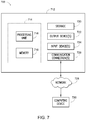
- FIG. 1 is an illustration of an exemplary component diagram of a system for operation of an autonomous all-terrain vehicle (ATV), according to one aspect.
- ATV autonomous all-terrain vehicle
- FIG. 2 is an illustration of an exemplary component diagram of a system for operation of an autonomous all-terrain vehicle (ATV), according to one aspect.
- ATV autonomous all-terrain vehicle
- FIG. 3 is an illustration of an exemplary flow diagram of a method for operation of an autonomous ATV, according to one aspect.
- FIG. 4 is an illustration of an exemplary usage scenario for the system for operation of the autonomous ATV of FIG. 1 or FIG. 2 .
- FIG. 5 is an illustration of an exemplary usage scenario for the system for operation of the autonomous ATV of FIG. 1 or FIG. 2 .
- FIG. 6 is an illustration of an example computer-readable medium or computer-readable device including processor-executable instructions configured to embody one or more of the provisions set forth herein, according to one aspect.
- FIG. 7 is an illustration of an example computing environment where one or more of the provisions set forth herein are implemented, according to one aspect.
- Vehicle refers to any moving vehicle that is capable of carrying one or more human occupants and is powered by any form of energy.
- a motor vehicle includes one or more engines.
- vehicle may also refer to an autonomous vehicle and/or self-driving vehicle powered by any form of energy.
- the autonomous vehicle may carry one or more human occupants or other cargo.
- vehicle may include vehicles that are automated or non-automated with pre-determined paths or free-moving vehicles. It will be appreciated that a vehicle may be an electric vehicle (EV) or an internal combustion (IC) vehicle with an internal combustion engine.
- EV electric vehicle
- IC internal combustion
- Obstacle refers to any objects in a roadway or along a path being travelled by the vehicle and may include pedestrians, other vehicles, animals, debris, potholes, etc. Further, an ‘obstacle’ may include most any traffic condition, road condition, weather condition, features of the environment, etc. Examples of obstacles may include, but are not necessarily limited to other vehicles (e.g., obstacle vehicle), buildings, landmarks, obstructions in the roadway, road segments, intersections, etc. Thus, obstacles may be found, detected, or associated with a path, one or more road segments, etc. along a route on which the vehicle is travelling or is projected to travel along.
- vehicles e.g., obstacle vehicle
- buildings e.g., landmarks, obstructions in the roadway, road segments, intersections, etc.
- Module includes, but is not limited to, a non-transitory computer readable medium that stores instructions, instructions in execution on a machine, hardware, firmware, software in execution on a machine, and/or combinations of each to perform a function(s) or an action(s), and/or to cause a function or action from another module, method, and/or system.
- a module may include logic, a software controlled microprocessor, a discrete logic circuit, an analog circuit, a digital circuit, a programmed logic device, a memory device containing executing or executable instructions, logic gates, a combination of gates, and/or other circuit components, such as the modules, systems, devices, units, or any of the components of FIG. 1 . Multiple modules may be combined into one module and single modules may be distributed among multiple modules.
- Bus refers to an interconnected architecture that is operably connected to other computer components inside a computer or between computers.
- the bus may transfer data between the computer components.
- the bus may be a memory bus, a memory processor, a peripheral bus, an external bus, a crossbar switch, and/or a local bus, among others.
- the bus may also be a vehicle bus that interconnects components inside a vehicle using protocols such as Media Oriented Systems Transport (MOST), Controller Area Network (CAN), Local Interconnect network (LIN), among others.
- MOST Media Oriented Systems Transport
- CAN Controller Area Network
- LIN Local Interconnect network
- Communication refers to a communication between two or more computing devices (e.g., computer, personal digital assistant, cellular telephone, network device) and may be, for example, a network transfer, a file transfer, an applet transfer, an email, a hypertext transfer protocol (HTTP) transfer, and so on.
- a computer communication may occur across, for example, a wireless system (e.g., IEEE 802.11), an Ethernet system (e.g., IEEE 802.3), a token ring system (e.g., IEEE 802.5), a local area network (LAN), a wide area network (WAN), a point-to-point system, a circuit switching system, a packet switching system, among others.
- Operaable connection is one in which signals, physical communications, and/or logical communications may be sent and/or received.
- An operable connection may include a wireless interface, a physical interface, a data interface, and/or an electrical interface.
- one or more of the components of FIG. 1 may be operably connected with one another, thereby facilitating communication therebetween.
- Mobile device is a computing device typically having a display screen with user input (e.g., touch, keyboard) and a processor for computing.
- Mobile devices include, but are not limited to, handheld devices, portable devices, remote devices, smartphones, smartwatches, key fobs, laptops, tablets, and e-readers.
- V2X may be used to describe “vehicle-to-everything” communications, and variations of V2X designations may depend on the intended user that is transmitting DSRC signals, and “V2V” may be used to describe “vehicle-to-vehicle” communications.
- infer generally refers to the process of reasoning about or inferring states of a system, a component, an environment, a user from one or more observations captured via events or data, etc. Inference may be employed to identify a context or an action or may be employed to generate a probability distribution over states, for example.
- An inference may be probabilistic. For example, computation of a probability distribution over states of interest based on a consideration of data or events. Inference may also refer to techniques employed for composing higher-level events from a set of events or data. Such inference may result in the construction of new events or new actions from a set of observed events or stored event data, whether or not the events are correlated in close temporal proximity, and whether the events and data come from one or several event and data sources.
- FIG. 1 is an illustration of an exemplary component diagram of a system 100 for operation of an autonomous all-terrain vehicle (ATV), according to one aspect.
- the system 100 for operation of an autonomous ATV may include a controller 110 which includes a processor 112 and a memory 114 , a location unit 120 which includes a global positioning system (GPS) unit 122 , a navigation module 130 , a safety logic 132 , a sensor module 140 which may include a light detection and ranging (LIDAR) sensor, an image capture device 144 , a wheel speed sensor 146 , an interface module 150 which may include a display 152 , hardware buttons 154 (e.g., an emergency stop button), and/or software buttons 156 , a communications module 160 which may include a dedicated short range communications (DSRC) antenna 162 , and a drive controller driving a power steering system 174 , a throttle control system 176 , or a brake control system 178 .
- GPS global positioning system
- a navigation module 130 includes
- a controller area network (CAN) bus 172 may communicatively couple one or more of these aforementioned components, thereby enabling communication between the respective components. Stated another way, the modules and components of FIG. 1 may be operably connected and communicate among each other via the CAN bus 172 . According to one aspect, the system 100 for operation of an autonomous ATV may be implemented as a part of an internal combustion (IC) autonomous ATV.
- IC internal combustion
- FIG. 2 is an illustration of an exemplary component diagram of a system 100 for operation of an autonomous all-terrain vehicle (ATV), according to one aspect.
- the system 200 of FIG. 2 is similar to the system 100 of FIG. 1 , except that the system 200 of FIG. 2 is for an electric vehicle (EV) version of the autonomous ATV, which may include a drive motor control system 270 driving a motor controller 272 rather than the drive controller 170 of the system 100 of FIG. 1 .
- EV electric vehicle
- FIG. 2 may be configured and/or perform similar functions and concepts or features associated with the EV may be applied to the IC autonomous ATV of FIG. 1 and vice versa.
- the controller 110 may receive one or more commands associated with autonomous driving of the vehicle. These commands may be initiated, for example, at the interface module 150 via one or more of the hardware buttons 154 or one or more of the software buttons 156 , or via a remote device, such as a remote control for the autonomous ATV.
- the location unit 120 may include the GPS unit 122 and determine a current location associated with the autonomous ATV, as well as a destination location associated with the command for autonomous driving. In this way, the location unit 120 may receive a GPS location associated with the autonomous ATV, such as by locating the autonomous ATV using satellites, thereby providing a precise set of geographical coordinates associated with the autonomous ATV.
- the communications module 160 may receive information from one or more sources, such as, for example, other vehicles 182 , a server 184 , or the remote device 186 .
- sources such as, for example, other vehicles 182 , a server 184 , or the remote device 186 .
- Examples of information which may be received include map data associated with a current path, such as the path from the current location of the autonomous ATV to the destination location.
- the navigation module 130 may determine a route, based on map information from the communications module 160 or stored locally on the memory 114 of the autonomous ATV, from the current location of the autonomous ATV to the destination location. According to one aspect, the navigation module 130 may determine the route based on obstacles detected by the sensor module 140 . In other words, the navigation module 130 may identify a potential path in the operating environment through which the autonomous ATV may pass. The navigation module 130 may also present information to a driver or occupant of the autonomous ATV via the interface to show progress of a trip.
- the sensor module 140 may include different types of sensors, such as a Light Detection and Ranging (LIDAR) sensor 142 , the image capture device 144 , a radar sensor, etc.
- the LIDAR sensor 142 may be a light based sensor which facilitates object detection or environment detection.
- the sensor module 140 may sense or detect an obstacle around the autonomous ATV. If the sensor module 140 detects an obstacle which is obstructing a path associated with the autonomous ATV, the navigation module 130 may, in response, modify a route or current route of the autonomous ATV to navigate around the detected obstacle, thereby enabling the sensor module 140 to identify potential paths from a current location associated with the autonomous ATV to a current location of the leader or leader device.
- the navigation module 130 may make a determination as to whether a route change or an alternative route should be considered.
- the navigation module 130 may make this determination based on a size of the obstacle, topology of alternative routes, a state of the surrounding environment, etc. For example, if ground conditions are muddy, rainy, slick, icy, snowy, dry, etc. the navigation module 130 may recommend or determine the alternative route accordingly.
- the navigation module 130 determines whether the obstacle impedes a current route of the autonomous ATV. Stated another way, the navigation module 130 may determine an alternative current route for the autonomous ATV based on the current route, whether the obstacle impedes the current route of the autonomous ATV, and a feature of the operating environment (e.g., topology, whether the terrain is passable, weather, ground conditions, ice thickness associated with a body of water, difficulty associated with an alternative route, etc.).
- a feature of the operating environment e.g., topology, whether the terrain is passable, weather, ground conditions, ice thickness associated with a body of water, difficulty associated with an alternative route, etc.
- the navigation module 130 may determine one or more driving parameters to be implemented by one or more components of the autonomous ATV during autonomous travel. For example, the navigation module 130 may determine one or more driving parameters based on map data and/or sensed obstacles associated with the path from the current location to the destination location. Examples of driving parameters associated with vehicle components include coordinate information, velocity, acceleration, trajectory, yaw rate, steering angle, throttle angle, etc. If the terrain surround the autonomous ATV is steep, the navigation module 130 may decrease a gear of the vehicle and/or determine a lower velocity than if the terrain were flat.
- the sensor module 140 may include the wheel speed sensor 146 detecting an angular velocity of a wheel of the autonomous ATV.
- the navigation module 130 may determine one or more of the driving parameters based on the vehicle wheel speed and the map data.
- a lookup table may be provided on the server 184 based on an incline angle, temperature, humidity, road surface conditions, terrain type (e.g., rock, gravel, grass, mud, snow, ice), etc. to determine one or more of the corresponding driving parameters.
- the safety logic 132 may implement an emergency stop based on an error determined by the controller 110 or an error determined by the safety logic 132 .
- the controller 110 may monitor the location unit 120 , the navigation module 130 , the sensor module 140 , the interface module 150 , the communications module 160 , the drive controller 170 , or the CAN bus 172 for the error.
- Examples of errors determined by the controller 110 may include a GPS error associated with signal loss or a real time kinematic (RTK) correction error, invalid sensor data from the sensor module 140 , a field-programmable gate array (FPGA) watchdog timer error, mechanical errors sensed by the sensor module 140 (e.g., errors associated with the brake control system 178 , the power steering system 174 , and the throttle control system 176 , etc.).
- the sensor module 140 may include the wheel speed sensor 146 , which detects an angular velocity of a wheel of the autonomous ATV.
- the safety logic 132 may determine or implement the emergency stop based on the wheel speed sensor data.
- Other errors may include a CAN bus error, such as a delay in communication between one or more of the components of FIG. 1 or a loss of frames, for example.
- the safety logic 132 may monitor the controller 110 for errors associated with the controller 110 . In this way, even if the controller 110 were to malfunction, another component of the autonomous ATV may detect such an error. Thus, if the safety logic 132 detects an error associated with the controller 110 , the safety logic 132 would, in response to this error, implement the emergency stop based on the determined error associated with the controller 110 and based on the maps information and surrounding terrain. For example, in a hilly environment, the safety logic 132 may implement the emergency stop as a gradual increasing application of the brakes, rather than as a sudden stop, which may be implemented if the sensor module 140 detects a sudden obstacle, such as a pedestrian moving in front of the autonomous ATV.
- the safety logic 132 may causes the interface to render, on the display 152 of the autonomous ATV or on a display of the remote device 186 , a notification based on a battery level of the autonomous ATV and a distance of the path from the current location to the destination location.
- the safety logic 132 may cause the interface to render a corresponding warning.
- the EV autonomous ATV may not be able to make it up an incline at x distance at a battery level while being able to traverse x distance on a flat path due to the current being drawn).
- the autonomous ATV is an internal combustion (IC) vehicle
- IC internal combustion
- the safety logic 132 may cause the interface to render a corresponding warning.
- the safety logic 132 may monitor a distance between the remote device 186 and the autonomous ATV. When the distance between the remote device 186 and the autonomous ATV increases past an out of range threshold distance, the safety logic 132 may cause the interface to render an out of range warning or the safety logic 132 may implement the emergency stop.
- the out of range warning may be provided at a first out of range threshold distance and the emergency stop may be applied at a second out of range threshold distance, where the second out of range threshold distance is greater than the first out of range threshold distance.
- the sensor module 140 may sense an obstacle along the path from the current location of the autonomous ATV to the destination location. Further, the sensor module 140 may sense errors associated with one or more autonomous ATV vehicle components, including but not limited to the brake control system 178 , the power steering system 174 , and the throttle control system 176 , for example.
- the interface module 150 may render information associated with a path, route, or trip for a passenger, driver, or occupant of the autonomous ATV, such as via the display 152 .
- the interface module 150 may also include a touch screen interface, for example. Additionally, when a button is pressed, the interface module 150 may transmit a corresponding command, via the CAN bus 172 , to the controller 110 of the autonomous ATV. In this regard, the controller 110 may receive the corresponding command from the interface module 150 and facilitate execution of that command (e.g., drive autonomously to a ‘home’ location).
- the communications module 160 may facilitate V2V and/or V2X communications.
- the communications module 160 may include the DSRC module 162 , an antenna, a receiver, a transmitter, and/or a transceiver.
- the communications module 160 may receive information from external sources, such as another vehicle 182 (e.g., thereby facilitating V2V communications), a server 184 (e.g., thereby facilitating V2X communications), a remote device 186 , etc.
- the communications module 160 may receive obstacle or environment information associated with the operating environment from the other vehicle or map information from the server 184 . In this way, the communications module 160 may receive a variety of information from different sources.
- the communications module 160 may transmit a path from the current location to the destination location as a desired path to the server 184 .
- the drive controller 170 or the drive motor control system 270 may control aspects of autonomous driving by implemented one or more of driving parameters.
- the drive controller 170 may drive the power steering system 174 , the throttle control system 176 , or the brake control system 178 , while the drive motor control system may drive the motor controller 272 , thereby implementing the driving parameters as an operating action or autonomous driving action.
- FIG. 3 is an illustration of an exemplary flow diagram of a method for operation of an autonomous ATV, according to one aspect.
- the autonomous ATV may be started.
- system initialization may occur, including initialization of the controller 110 , the CAN bus 172 , and/or one or more other components.
- one or more failures may be checked.
- An example of the failure check may include a check for one or more mechanical failures or mechanical errors.
- the controller 110 or the safety logic 132 may determine whether any mechanical errors are present at 306 . If no errors are detected at 306 , the autonomous ATV may run initialization commands at 308 .
- the controller 110 may monitor the CAN for errors.
- the controller 110 may determine whether a CAN failure or error is detected. If no CAN error is detected at 312 , the system may enter manual mode or autonomous mode at 314 .
- the autonomous ATV may receive inputs from the autonomous control system (e.g., the controller 110 , navigation module 130 , sensor module 140 , etc.) at 316 .
- the autonomous control system e.g., the controller 110 , navigation module 130 , sensor module 140 , etc.
- one or more driving parameters may be determined based on map data associated with a path from a current location to a destination location.
- the navigation module 130 may determine one or more driving parameters and provide these as commands to the motor controller at 332 or as commands to the throttle, brake, motor controller and the drive motor controller at 334 .
- the ATV may be stopped in a normal fashion (e.g., key stop) and shut down 338 .
- inputs may be received from the remote control at 320 . If errors are detected, at 306 or 312 , an emergency stop may be implemented at 330 , and thus an emergency stop may be performed based on an error determined by a controller 110 or a safety logic 132 of the autonomous ATV.
- FIG. 4 is an illustration of an exemplary usage scenario for the system for operation of the autonomous ATV of FIG. 1 or FIG. 2 .
- an autonomous ATV may travel from a current location 410 autonomously along path 412 , from 410 to 420 , to 430 to 440 (following 412 ′, 412 ′′, 412 ′′′, 412 ′′′′), which may be waypoints set by the navigation module 130 in association with determination of the route from the current location to the destination location.
- an emergency stop may be performed or implemented by the safety logic 132 based on one or more of the aforementioned errors, such as a GPS error associated with signal loss or a real time kinematic (RTK) correction error, invalid sensor data from the sensor module 140 , a FPGA watchdog timer error, or a mechanical error.
- a GPS error associated with signal loss or a real time kinematic (RTK) correction error
- RTK real time kinematic
- FIG. 5 is an illustration of an exemplary usage scenario for the system for operation of the autonomous ATV of FIG. 1 or FIG. 2 .
- the autonomous ATV may utilize the LIDAR sensor 142 and/or maps information received from the server 184 to determine a path from the start location 510 to the home location 520 to facilitate a drive ‘home’ autonomous operation.
- a first route 530 may be determined or a second route 550 may be determined.
- the first route 530 is more on road, although an obstacle 560 (e.g., a downed tree) may cause the navigation module 130 to determine an alternative slightly off-road travel segment at 560 to mitigate a collision with the obstacle 560 .
- an obstacle 560 e.g., a downed tree
- the navigation module 130 may determine that the second route 550 as the selected route. In this way, control of the autonomous ATV may be provided.
- Still another aspect involves a computer-readable medium including processor-executable instructions configured to implement one aspect of the techniques presented herein.
- An embodiment of a computer-readable medium or a computer-readable device devised in these ways is illustrated in FIG. 6 , wherein an implementation 600 includes a computer-readable medium 608 , such as a CD-R, DVD-R, flash drive, a platter of a hard disk drive, etc., on which is encoded computer-readable data 606 .
- This encoded computer-readable data 606 such as binary data including a plurality of zero's and one's as shown in 606 , in turn includes a set of processor-executable computer instructions 604 configured to operate according to one or more of the principles set forth herein.
- the processor-executable computer instructions 604 may be configured to perform a method 602 , such as the method 300 of FIG. 3 .
- the processor-executable computer instructions 604 may be configured to implement a system, such as the system 100 of FIG. 1 or the system 200 of FIG. 2 .
- Many such computer-readable media may be devised by those of ordinary skill in the art that are configured to operate in accordance with the techniques presented herein.
- a component may be, but is not limited to being, a process running on a processor, a processor, an object, an executable, a thread of execution, a program, or a computer.
- an application running on a controller and the controller may be a component.
- One or more components residing within a process or thread of execution and a component may be localized on one computer or distributed between two or more computers.
- the claimed subject matter is implemented as a method, apparatus, or article of manufacture using standard programming or engineering techniques to produce software, firmware, hardware, or any combination thereof to control a computer to implement the disclosed subject matter.
- article of manufacture as used herein is intended to encompass a computer program accessible from any computer-readable device, carrier, or media.
- FIG. 7 and the following discussion provide a description of a suitable computing environment to implement embodiments of one or more of the provisions set forth herein.
- the operating environment of FIG. 7 is merely one example of a suitable operating environment and is not intended to suggest any limitation as to the scope of use or functionality of the operating environment.
- Example computing devices include, but are not limited to, personal computers, server computers, handheld or laptop devices, mobile devices, such as mobile phones, Personal Digital Assistants (PDAs), media players, and the like, multiprocessor systems, consumer electronics, mini computers, mainframe computers, distributed computing environments that include any of the above systems or devices, etc.
- PDAs Personal Digital Assistants
- Computer readable instructions may be distributed via computer readable media as will be discussed below.
- Computer readable instructions may be implemented as program modules, such as functions, objects, Application Programming Interfaces (APIs), data structures, and the like, that perform one or more tasks or implement one or more abstract data types.
- APIs Application Programming Interfaces
- FIG. 7 illustrates a system 700 including a computing device 712 configured to implement one aspect provided herein.
- computing device 712 includes at least one processing unit 716 and memory 718 .
- memory 718 may be volatile, such as RAM, non-volatile, such as ROM, flash memory, etc., or a combination of the two. This configuration is illustrated in FIG. 7 by dashed line 714 .
- computing device 712 includes additional features or functionality.
- computing device 712 may include additional storage such as removable storage or non-removable storage, including, but not limited to, magnetic storage, optical storage, etc.
- additional storage is illustrated in FIG. 7 by storage 720 .
- computer readable instructions to implement one aspect provided herein are in storage 720 .
- Storage 720 may store other computer readable instructions to implement an operating system, an application program, etc.
- Computer readable instructions may be loaded in memory 718 for execution by processing unit 716 , for example.
- Computer storage media includes volatile and nonvolatile, removable and non-removable media implemented in any method or technology for storage of information such as computer readable instructions or other data.
- Memory 718 and storage 720 are examples of computer storage media.
- Computer storage media includes, but is not limited to, RAM, ROM, EEPROM, flash memory or other memory technology, CD-ROM, Digital Versatile Disks (DVDs) or other optical storage, magnetic cassettes, magnetic tape, magnetic disk storage or other magnetic storage devices, or any other medium which may be used to store the desired information and which may be accessed by computing device 712 . Any such computer storage media is part of computing device 712 .
- Computer readable media includes communication media.
- Communication media typically embodies computer readable instructions or other data in a “modulated data signal” such as a carrier wave or other transport mechanism and includes any information delivery media.
- modulated data signal includes a signal that has one or more of its characteristics set or changed in such a manner as to encode information in the signal.
- Computing device 712 includes input device(s) 724 such as keyboard, mouse, pen, voice input device, touch input device, infrared cameras, video input devices, or any other input device.
- Output device(s) 722 such as one or more displays, speakers, printers, or any other output device may be included with computing device 712 .
- Input device(s) 724 and output device(s) 722 may be connected to computing device 712 via a wired connection, wireless connection, or any combination thereof.
- an input device or an output device from another computing device may be used as input device(s) 724 or output device(s) 722 for computing device 712 .
- Computing device 712 may include communication connection(s) 726 to facilitate communications with one or more other devices 730 , such as through network 728 , for example.
- first”, “second”, or the like are not intended to imply a temporal aspect, a spatial aspect, an ordering, etc. Rather, such terms are merely used as identifiers, names, etc. for features, elements, items, etc.
- a first channel and a second channel generally correspond to channel A and channel B or two different or two identical channels or the same channel.
- “comprising”, “comprises”, “including”, “includes”, or the like generally means comprising or including, but not limited to.
Abstract
Description
Claims (20)
Priority Applications (1)
| Application Number | Priority Date | Filing Date | Title |
|---|---|---|---|
| US15/910,832 US10967875B2 (en) | 2018-01-05 | 2018-03-02 | Control system for autonomous all-terrain vehicle (ATV) |
Applications Claiming Priority (2)
| Application Number | Priority Date | Filing Date | Title |
|---|---|---|---|
| US201862613943P | 2018-01-05 | 2018-01-05 | |
| US15/910,832 US10967875B2 (en) | 2018-01-05 | 2018-03-02 | Control system for autonomous all-terrain vehicle (ATV) |
Publications (2)
| Publication Number | Publication Date |
|---|---|
| US20190210612A1 US20190210612A1 (en) | 2019-07-11 |
| US10967875B2 true US10967875B2 (en) | 2021-04-06 |
Family
ID=67140463
Family Applications (1)
| Application Number | Title | Priority Date | Filing Date |
|---|---|---|---|
| US15/910,832 Active 2038-08-01 US10967875B2 (en) | 2018-01-05 | 2018-03-02 | Control system for autonomous all-terrain vehicle (ATV) |
Country Status (1)
| Country | Link |
|---|---|
| US (1) | US10967875B2 (en) |
Families Citing this family (6)
| Publication number | Priority date | Publication date | Assignee | Title |
|---|---|---|---|---|
| US10606252B2 (en) * | 2016-10-31 | 2020-03-31 | Shindengen Electric Manufacturing Co., Ltd. | Control device including one microcomputer for controlling a motor vehicle which may immediately stop rotations of the motor when an abnormal condition occurs |
| GB2586302B (en) * | 2019-04-29 | 2021-09-22 | Motional Ad Llc | Systems and methods for implementing an autonomous vehicle response to sensor failure |
| US11315427B2 (en) | 2019-06-11 | 2022-04-26 | Toyota Motor North America, Inc. | Vehicle-to-vehicle sensor data sharing |
| US10769953B1 (en) * | 2019-06-11 | 2020-09-08 | Toyota Motor North America, Inc. | Vehicle-to-vehicle sensor data sharing |
| CN112389440B (en) * | 2020-11-07 | 2021-06-04 | 吉林大学 | Vehicle driving risk prediction method in off-road environment based on vehicle-road action mechanism |
| US11766949B2 (en) * | 2021-06-01 | 2023-09-26 | Ford Global Technologies, Llc | Charging notification strategies for vehicle-to-recreational vehicle energy transfer systems |
Citations (19)
| Publication number | Priority date | Publication date | Assignee | Title |
|---|---|---|---|---|
| US6442708B1 (en) * | 1999-12-14 | 2002-08-27 | Honeywell International Inc. | Fault localization and health indication for a controller area network |
| US20070219666A1 (en) * | 2005-10-21 | 2007-09-20 | Filippov Mikhail O | Versatile robotic control module |
| US20100106356A1 (en) * | 2008-10-24 | 2010-04-29 | The Gray Insurance Company | Control and systems for autonomously driven vehicles |
| US7840355B2 (en) | 1997-10-22 | 2010-11-23 | Intelligent Technologies International, Inc. | Accident avoidance systems and methods |
| US7944340B1 (en) * | 2006-09-28 | 2011-05-17 | Lear Corporation | System and method for two-way remote activation with adaptive protocol |
| US7979173B2 (en) | 1997-10-22 | 2011-07-12 | Intelligent Technologies International, Inc. | Autonomous vehicle travel control systems and methods |
| US8036788B2 (en) | 1995-06-07 | 2011-10-11 | Automotive Technologies International, Inc. | Vehicle diagnostic or prognostic message transmission systems and methods |
| US8050863B2 (en) | 2006-03-16 | 2011-11-01 | Gray & Company, Inc. | Navigation and control system for autonomous vehicles |
| US8280595B2 (en) | 2008-08-12 | 2012-10-02 | Cnh America Llc | System and method employing short range communications for communicating and exchanging operational and logistical status information among a plurality of agricultural machines |
| US8352112B2 (en) | 2009-04-06 | 2013-01-08 | GM Global Technology Operations LLC | Autonomous vehicle management |
| US20150234382A1 (en) | 2014-02-17 | 2015-08-20 | Industry-Academic Cooperation Foundation, Yonsei University | Apparatus and method for controlling driving device of self-driving vehicle |
| US20150331422A1 (en) | 2013-12-31 | 2015-11-19 | Harbrick LLC | Autonomous Vehicle Interface System |
| US9396661B2 (en) | 2013-04-17 | 2016-07-19 | Denso Corporation | Platoon travel system |
| US20170097640A1 (en) | 2015-10-06 | 2017-04-06 | Northrop Grumman Systems Corporation | Autonomous vehicle control system |
| US20170123422A1 (en) | 2015-11-04 | 2017-05-04 | Zoox, Inc. | Interactive autonomous vehicle command controller |
| US20170185956A1 (en) | 2015-07-23 | 2017-06-29 | Pinc Solutions | System and method for determining and controlling status and location of an object |
| US20170227957A1 (en) * | 2016-02-04 | 2017-08-10 | Proxy Technologies, Inc. | Unmanned vehicles, systems, apparatus and methods for controlling unmanned vehicles |
| US10042359B1 (en) * | 2016-01-22 | 2018-08-07 | State Farm Mutual Automobile Insurance Company | Autonomous vehicle refueling |
| US20180275654A1 (en) * | 2015-09-03 | 2018-09-27 | Commonwealth Scientific And Industrial Research Or Ganisation | Unmanned Aerial Vehicle Control Techniques |
-
2018
- 2018-03-02 US US15/910,832 patent/US10967875B2/en active Active
Patent Citations (23)
| Publication number | Priority date | Publication date | Assignee | Title |
|---|---|---|---|---|
| US8036788B2 (en) | 1995-06-07 | 2011-10-11 | Automotive Technologies International, Inc. | Vehicle diagnostic or prognostic message transmission systems and methods |
| US7840355B2 (en) | 1997-10-22 | 2010-11-23 | Intelligent Technologies International, Inc. | Accident avoidance systems and methods |
| US7979173B2 (en) | 1997-10-22 | 2011-07-12 | Intelligent Technologies International, Inc. | Autonomous vehicle travel control systems and methods |
| US6442708B1 (en) * | 1999-12-14 | 2002-08-27 | Honeywell International Inc. | Fault localization and health indication for a controller area network |
| US9043016B2 (en) | 2005-10-21 | 2015-05-26 | Deere & Company | Versatile robotic control module |
| US20070219666A1 (en) * | 2005-10-21 | 2007-09-20 | Filippov Mikhail O | Versatile robotic control module |
| US8050863B2 (en) | 2006-03-16 | 2011-11-01 | Gray & Company, Inc. | Navigation and control system for autonomous vehicles |
| US7944340B1 (en) * | 2006-09-28 | 2011-05-17 | Lear Corporation | System and method for two-way remote activation with adaptive protocol |
| US8280595B2 (en) | 2008-08-12 | 2012-10-02 | Cnh America Llc | System and method employing short range communications for communicating and exchanging operational and logistical status information among a plurality of agricultural machines |
| US20100106356A1 (en) * | 2008-10-24 | 2010-04-29 | The Gray Insurance Company | Control and systems for autonomously driven vehicles |
| US8126642B2 (en) | 2008-10-24 | 2012-02-28 | Gray & Company, Inc. | Control and systems for autonomously driven vehicles |
| US8352112B2 (en) | 2009-04-06 | 2013-01-08 | GM Global Technology Operations LLC | Autonomous vehicle management |
| US8352111B2 (en) | 2009-04-06 | 2013-01-08 | GM Global Technology Operations LLC | Platoon vehicle management |
| US9396661B2 (en) | 2013-04-17 | 2016-07-19 | Denso Corporation | Platoon travel system |
| US20150331422A1 (en) | 2013-12-31 | 2015-11-19 | Harbrick LLC | Autonomous Vehicle Interface System |
| US20150234382A1 (en) | 2014-02-17 | 2015-08-20 | Industry-Academic Cooperation Foundation, Yonsei University | Apparatus and method for controlling driving device of self-driving vehicle |
| US9360867B2 (en) | 2014-02-17 | 2016-06-07 | Industry-Academic Cooperation Foundation, Yonsei University | Apparatus and method for controlling driving device of self-driving vehicle |
| US20170185956A1 (en) | 2015-07-23 | 2017-06-29 | Pinc Solutions | System and method for determining and controlling status and location of an object |
| US20180275654A1 (en) * | 2015-09-03 | 2018-09-27 | Commonwealth Scientific And Industrial Research Or Ganisation | Unmanned Aerial Vehicle Control Techniques |
| US20170097640A1 (en) | 2015-10-06 | 2017-04-06 | Northrop Grumman Systems Corporation | Autonomous vehicle control system |
| US20170123422A1 (en) | 2015-11-04 | 2017-05-04 | Zoox, Inc. | Interactive autonomous vehicle command controller |
| US10042359B1 (en) * | 2016-01-22 | 2018-08-07 | State Farm Mutual Automobile Insurance Company | Autonomous vehicle refueling |
| US20170227957A1 (en) * | 2016-02-04 | 2017-08-10 | Proxy Technologies, Inc. | Unmanned vehicles, systems, apparatus and methods for controlling unmanned vehicles |
Also Published As
| Publication number | Publication date |
|---|---|
| US20190210612A1 (en) | 2019-07-11 |
Similar Documents
| Publication | Publication Date | Title |
|---|---|---|
| US10967875B2 (en) | Control system for autonomous all-terrain vehicle (ATV) | |
| KR102506647B1 (en) | steering angle calibration | |
| US10963462B2 (en) | Enhancing autonomous vehicle perception with off-vehicle collected data | |
| CN112368662B (en) | Directional adjustment actions for autonomous vehicle operation management | |
| CN110667598B (en) | Method for handling sensor faults in autonomous vehicles | |
| EP3602220B1 (en) | Dynamic sensor selection for self-driving vehicles | |
| EP3299921B1 (en) | Location specific assistance for an autonomous vehicle control system | |
| US9815462B2 (en) | Path determination for automated vehicles | |
| US11724691B2 (en) | Systems and methods for estimating the risk associated with a vehicular maneuver | |
| JP6985203B2 (en) | Behavior prediction device | |
| JP2019532292A (en) | Autonomous vehicle with vehicle location | |
| WO2019168530A1 (en) | Transportation network infrastructure for autonomous vehicle decision making | |
| JP2021504825A (en) | Autonomous vehicle operation management plan | |
| US20230020040A1 (en) | Batch control for autonomous vehicles | |
| US10705529B2 (en) | Autonomous all-terrain vehicle (ATV) | |
| KR102461986B1 (en) | Road surface condition guided decision making and prediction | |
| US20220283587A1 (en) | Controlling an autonomous vehicle using a proximity rule | |
| KR20220147055A (en) | Operation of an autonomous vehicle based on availability of navigational information | |
| US10810875B2 (en) | Navigation of impaired vehicle | |
| US20220348223A1 (en) | Autonomous vehicle to oversight system communications | |
| CN114080341A (en) | Techniques to contact a remote operator | |
| US11767032B2 (en) | Direct autonomous vehicle to autonomous vehicle communications | |
| US20220348222A1 (en) | Oversight system to autonomous vehicle communications | |
| KR20210109615A (en) | Classification of perceived objects based on activity | |
| US20230365143A1 (en) | System and method for remote control guided autonomy for autonomous vehicles |
Legal Events
| Date | Code | Title | Description |
|---|---|---|---|
| AS | Assignment |
Owner name: HONDA MOTOR CO., LTD., JAPAN Free format text: ASSIGNMENT OF ASSIGNORS INTEREST;ASSIGNORS:VANLANDINGHAM, JOSHUA D.;GOVINDARAJAN, MARUTHI;VITTALA, KAVYA;AND OTHERS;SIGNING DATES FROM 20180220 TO 20180223;REEL/FRAME:045094/0014 |
|
| FEPP | Fee payment procedure |
Free format text: ENTITY STATUS SET TO UNDISCOUNTED (ORIGINAL EVENT CODE: BIG.); ENTITY STATUS OF PATENT OWNER: LARGE ENTITY |
|
| STPP | Information on status: patent application and granting procedure in general |
Free format text: NON FINAL ACTION MAILED |
|
| STPP | Information on status: patent application and granting procedure in general |
Free format text: RESPONSE TO NON-FINAL OFFICE ACTION ENTERED AND FORWARDED TO EXAMINER |
|
| STPP | Information on status: patent application and granting procedure in general |
Free format text: FINAL REJECTION MAILED |
|
| STPP | Information on status: patent application and granting procedure in general |
Free format text: ADVISORY ACTION MAILED |
|
| STPP | Information on status: patent application and granting procedure in general |
Free format text: DOCKETED NEW CASE - READY FOR EXAMINATION |
|
| STPP | Information on status: patent application and granting procedure in general |
Free format text: NON FINAL ACTION MAILED |
|
| STPP | Information on status: patent application and granting procedure in general |
Free format text: RESPONSE TO NON-FINAL OFFICE ACTION ENTERED AND FORWARDED TO EXAMINER |
|
| STPP | Information on status: patent application and granting procedure in general |
Free format text: PUBLICATIONS -- ISSUE FEE PAYMENT VERIFIED |
|
| STCF | Information on status: patent grant |
Free format text: PATENTED CASE |