US10122213B2 - Wireless power supplying system - Google Patents
Wireless power supplying system Download PDFInfo
- Publication number
- US10122213B2 US10122213B2 US14/854,313 US201514854313A US10122213B2 US 10122213 B2 US10122213 B2 US 10122213B2 US 201514854313 A US201514854313 A US 201514854313A US 10122213 B2 US10122213 B2 US 10122213B2
- Authority
- US
- United States
- Prior art keywords
- power
- section
- power transmission
- resonance element
- control
- Prior art date
- Legal status (The legal status is an assumption and is not a legal conclusion. Google has not performed a legal analysis and makes no representation as to the accuracy of the status listed.)
- Active, expires
Links
Images


Classifications
-
- H—ELECTRICITY
- H02—GENERATION; CONVERSION OR DISTRIBUTION OF ELECTRIC POWER
- H02J—CIRCUIT ARRANGEMENTS OR SYSTEMS FOR SUPPLYING OR DISTRIBUTING ELECTRIC POWER; SYSTEMS FOR STORING ELECTRIC ENERGY
- H02J50/00—Circuit arrangements or systems for wireless supply or distribution of electric power
- H02J50/10—Circuit arrangements or systems for wireless supply or distribution of electric power using inductive coupling
- H02J50/12—Circuit arrangements or systems for wireless supply or distribution of electric power using inductive coupling of the resonant type
-
- B60L11/182—
-
- H02J17/00—
-
- H02J5/005—
-
- H—ELECTRICITY
- H02—GENERATION; CONVERSION OR DISTRIBUTION OF ELECTRIC POWER
- H02J—CIRCUIT ARRANGEMENTS OR SYSTEMS FOR SUPPLYING OR DISTRIBUTING ELECTRIC POWER; SYSTEMS FOR STORING ELECTRIC ENERGY
- H02J50/00—Circuit arrangements or systems for wireless supply or distribution of electric power
- H02J50/10—Circuit arrangements or systems for wireless supply or distribution of electric power using inductive coupling
-
- H—ELECTRICITY
- H02—GENERATION; CONVERSION OR DISTRIBUTION OF ELECTRIC POWER
- H02J—CIRCUIT ARRANGEMENTS OR SYSTEMS FOR SUPPLYING OR DISTRIBUTING ELECTRIC POWER; SYSTEMS FOR STORING ELECTRIC ENERGY
- H02J50/00—Circuit arrangements or systems for wireless supply or distribution of electric power
- H02J50/50—Circuit arrangements or systems for wireless supply or distribution of electric power using additional energy repeaters between transmitting devices and receiving devices
-
- H—ELECTRICITY
- H02—GENERATION; CONVERSION OR DISTRIBUTION OF ELECTRIC POWER
- H02J—CIRCUIT ARRANGEMENTS OR SYSTEMS FOR SUPPLYING OR DISTRIBUTING ELECTRIC POWER; SYSTEMS FOR STORING ELECTRIC ENERGY
- H02J50/00—Circuit arrangements or systems for wireless supply or distribution of electric power
- H02J50/90—Circuit arrangements or systems for wireless supply or distribution of electric power involving detection or optimisation of position, e.g. alignment
-
- H02J7/025—
-
- Y—GENERAL TAGGING OF NEW TECHNOLOGICAL DEVELOPMENTS; GENERAL TAGGING OF CROSS-SECTIONAL TECHNOLOGIES SPANNING OVER SEVERAL SECTIONS OF THE IPC; TECHNICAL SUBJECTS COVERED BY FORMER USPC CROSS-REFERENCE ART COLLECTIONS [XRACs] AND DIGESTS
- Y02—TECHNOLOGIES OR APPLICATIONS FOR MITIGATION OR ADAPTATION AGAINST CLIMATE CHANGE
- Y02T—CLIMATE CHANGE MITIGATION TECHNOLOGIES RELATED TO TRANSPORTATION
- Y02T10/00—Road transport of goods or passengers
- Y02T10/60—Other road transportation technologies with climate change mitigation effect
- Y02T10/70—Energy storage systems for electromobility, e.g. batteries
-
- Y02T10/7005—
-
- Y—GENERAL TAGGING OF NEW TECHNOLOGICAL DEVELOPMENTS; GENERAL TAGGING OF CROSS-SECTIONAL TECHNOLOGIES SPANNING OVER SEVERAL SECTIONS OF THE IPC; TECHNICAL SUBJECTS COVERED BY FORMER USPC CROSS-REFERENCE ART COLLECTIONS [XRACs] AND DIGESTS
- Y02—TECHNOLOGIES OR APPLICATIONS FOR MITIGATION OR ADAPTATION AGAINST CLIMATE CHANGE
- Y02T—CLIMATE CHANGE MITIGATION TECHNOLOGIES RELATED TO TRANSPORTATION
- Y02T10/00—Road transport of goods or passengers
- Y02T10/60—Other road transportation technologies with climate change mitigation effect
- Y02T10/7072—Electromobility specific charging systems or methods for batteries, ultracapacitors, supercapacitors or double-layer capacitors
-
- Y—GENERAL TAGGING OF NEW TECHNOLOGICAL DEVELOPMENTS; GENERAL TAGGING OF CROSS-SECTIONAL TECHNOLOGIES SPANNING OVER SEVERAL SECTIONS OF THE IPC; TECHNICAL SUBJECTS COVERED BY FORMER USPC CROSS-REFERENCE ART COLLECTIONS [XRACs] AND DIGESTS
- Y02—TECHNOLOGIES OR APPLICATIONS FOR MITIGATION OR ADAPTATION AGAINST CLIMATE CHANGE
- Y02T—CLIMATE CHANGE MITIGATION TECHNOLOGIES RELATED TO TRANSPORTATION
- Y02T90/00—Enabling technologies or technologies with a potential or indirect contribution to GHG emissions mitigation
- Y02T90/10—Technologies relating to charging of electric vehicles
- Y02T90/12—Electric charging stations
-
- Y02T90/122—
-
- Y—GENERAL TAGGING OF NEW TECHNOLOGICAL DEVELOPMENTS; GENERAL TAGGING OF CROSS-SECTIONAL TECHNOLOGIES SPANNING OVER SEVERAL SECTIONS OF THE IPC; TECHNICAL SUBJECTS COVERED BY FORMER USPC CROSS-REFERENCE ART COLLECTIONS [XRACs] AND DIGESTS
- Y02—TECHNOLOGIES OR APPLICATIONS FOR MITIGATION OR ADAPTATION AGAINST CLIMATE CHANGE
- Y02T—CLIMATE CHANGE MITIGATION TECHNOLOGIES RELATED TO TRANSPORTATION
- Y02T90/00—Enabling technologies or technologies with a potential or indirect contribution to GHG emissions mitigation
- Y02T90/10—Technologies relating to charging of electric vehicles
- Y02T90/14—Plug-in electric vehicles
Definitions
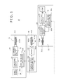
- FIG. 3 is a block diagram showing an example of a configuration of a wireless power supplying system according to a third embodiment of the present invention.
- FIG. 5 is a view showing an example of an application of the wireless power supplying system according to the fourth embodiment of the present invention.
- Second Embodiment (second example of the configuration of the wireless power supplying system)
- the wireless power supplying system 10 includes a power transmission device 20 , a power reception device 30 and a repeater device 40 .
- the power transmission coil section 21 includes a resonance coil 211 serving as a first resonance device. While the resonance coil is also called as consonance coil, the term resonance coil is used in the present specification.
- the control section 25 receives the detection result of the directional coupler 23 and outputs a control signal S 25 to the variable matching circuit 22 so that high efficiency power transmission can be achieved by impedance matching of the variable matching circuit 22 .
- the control section 25 includes a wireless communication unit 251 including a wireless communication function and can communicate control information regarding the transmission efficiency and detection result information of the passing and reflected powers by wireless communication with a control section 36 of the power reception device 30 side and a control section 43 of the repeater device 40 .
- a wireless communication unit 251 including a wireless communication function and can communicate control information regarding the transmission efficiency and detection result information of the passing and reflected powers by wireless communication with a control section 36 of the power reception device 30 side and a control section 43 of the repeater device 40 .
- the wireless communication for example, the Bluetooth, RFID or the like can be adopted.
- control section 43 controls the motor 42 so that the self resonance frequency of the resonance coil 411 may coincide with the self resonance frequencies of the resonance coil 411 of the power transmission device 20 and the resonance coil 311 of the power reception device 30 to establish a magnetic field resonance relationship thereby to transmit the power efficiency.
- the power reception device 30 side By the power reception device 30 side, power repeated by the repeater device 40 is received. However, the self resonance frequencies of the resonance coil 311 and the resonance coil 211 are equal to each other, and the power is supplied to the load 35 through the rectification circuit 34 .
- the efficiency can be improved, and a maximum efficiency is exhibited at a particular position.
Landscapes
- Engineering & Computer Science (AREA)
- Computer Networks & Wireless Communication (AREA)
- Power Engineering (AREA)
- Near-Field Transmission Systems (AREA)
- Charge And Discharge Circuits For Batteries Or The Like (AREA)
Abstract
Disclosed herein is a wireless power supplying system, including a power transmission device adapted to transmit power supplied thereto, a repeater device adapted to repeat the transmission power of the power transmission device, and a power reception device adapted to receive the power repeated by said repeater device.
Description
This application is a continuation of U.S. patent application Ser. No. 12/986,634 filed Jan. 7, 2011, the entirety of which is incorporated herein by reference to the extent permitted by law. The present application claims the benefit of priority to Japanese Patent Application No. JP 2010-006523 filed on Jan. 15, 2010 in the Japan Patent Office, the entirety of which is incorporated by reference herein to the extent permitted by law.
1. Field of the Invention
This invention relates to a wireless power supplying system of the non-contacting power supplying type capable of carrying out supplying and reception of power in a non-contacting or wireless fashion.
2. Description of the Related Art
An electromagnetic induction method is known as a method for carrying out supplying of power in a wireless state.
Further, in recent years, attention is paid to a wireless power supplying system and a charging system which uses a method called magnetic field resonance method which utilizes an electromagnetic resonance phenomenon.
In a contactless power supplying system of the electromagnetic induction type which is used most widely at present, it is necessary for a power supply source and a power supply destination, which is the power reception side, to commonly use magnetic fluxes. Therefore, in order to transmit power efficiently, it is necessary to dispose the power supply source and the power supply destination very closely to each other, and also alignment for coupling is significant.
Meanwhile, a contactless power supply system which utilizes an electromagnetic resonance phenomenon is advantageous in that, from the principle of the electromagnetic resonance phenomenon, power can be transmitted over a greater distance than that by the electromagnetic induction system and besides, even if the alignment is somewhat rough, the transmission efficiency does not drop very much.
It is to be noted that, as the electromagnetic resonance phenomenon, not only magnetic field resonance but also electric field resonance are available.
For example, Japanese Patent Laid-Open No. 2001-185939 (hereinafter described as Patent Document 1) discloses a wireless power supplying system which adopts the magnetic field resonance method.
In the technique disclosed in Patent Document 1, power is transmitted from a power supplying coil connected to a power supplying circuit to a resonance coil, also called consonance coil, by electromagnetic induction. Further, modulation of the frequency is carried out a capacitor connected to the resonance coil.
In recent years, a wireless power transmission technique has been reported which achieves transmission of power of 60 W over a distance of 2 m by adopting the magnetic field resonance system which utilizes a resonance phenomenon of a magnetic field.
Also development of a “wireless power supply system” of a high efficiency has been reported which transmits power of 60 W to drive an electronic apparatus at a place spaced by 50 cm by adopting the magnetic field resonance system.
Incidentally, in a wireless power supplying system of the magnetic field resonance type, it is a possible idea to dispose a repeater device between a power transmission device and a power reception device to improve the efficiency of the system. However, in this instance, a maximum efficiency is obtained at a certain particular position.
Actually, when a repeater device is disposed, position displacement or angle displacement sometimes occurs and this decreases the efficiency.
In this instance, while it seems a possible idea to manually adjust the position and the angle by manual operation, a measuring instrument or technique for exclusive use is required for the adjustment. Therefore, it is difficult to implement the adjustment by manual operation.
Therefore, it is desirable to provide a wireless power supplying system wherein power can be supplied with a high power supplying efficiency without the necessity for a measuring instrument.
According to the present invention, there is provided a wireless power supplying system including a power transmission device adapted to transmit power supplied thereto, a repeater device adapted to repeat the transmission power of the power transmission device, and a power reception device adapted to receive the power repeated by the repeater device, the power transmission device including a first resonance element for receiving the power supplied thereto and transmitting the received power, the repeater device including a second resonance element for receiving and transmitting the power transmitted thereto through a magnetic field resonance relationship, the power reception device including a third resonance element for receiving the power transmitted thereto from the repeater device though a magnetic field resonance relationship, the repeater device including a driving section capable of adjusting at least one of a disposition angle and a disposition position of the second resonance element in response to power transmission information of at least one of the power transmission device and the power reception device.
With the wireless power supplying system, power can be supplied with a high power supplying efficiency without the necessity for a measuring instrument for an exclusive use or the like.
In the following, embodiments of the present invention are described with reference to the drawings.
It is to be noted that the embodiments are described in order given below.
1. First Embodiment (first example of the configuration of the wireless power supplying system)
2. Second Embodiment (second example of the configuration of the wireless power supplying system)
3. Third Embodiment (third example of the configuration of the wireless power supplying system)
4. Fourth Embodiment (fourth example of the configuration of the wireless power supplying system)
The wireless power supplying system 10 includes a power transmission device 20, a power reception device 30 and a repeater device 40.
The power transmission device 20 includes a power transmission coil section 21, a variable matching circuit 22 serving as a first variable matching section, a directional coupler or excessively reflected power detection circuit 23 serving as a first detection section, a high-frequency signal generation circuit or signal source 24 and a control section 25 serving as a first control section.
The power transmission coil section 21 includes a resonance coil 211 serving as a first resonance device. While the resonance coil is also called as consonance coil, the term resonance coil is used in the present specification.
The resonance coil 211 is formed from an air-core coil, and when the self resonance frequency thereof coincides with that of a resonance coil 411 of the repeater device 40 or a resonance coil 311 of the power reception device 30, a magnetic field resonance relationship is established in which power is transmitted efficiently.
The variable matching circuit 22 has an impedance matching function at a power supplying point of the resonance coil 211 for carrying out impedance matching in accordance with a control signal S25 supplied thereto from the control section 25 and adjusts the impedance so that power can be transmitted efficiently.
The directional coupler 23 has a function of detecting passing power and reflected power in power transmission and supplies a result of the detection as a signal S23 to the control section 25.
The directional coupler 23 supplies high frequency power, that is, AC power, generated by the high frequency signal generation circuit 24 to the variable matching circuit 22 side.
The high frequency signal generation circuit 24 generates high frequency power for wireless power transmission.
The high frequency power generated by the high frequency signal generation circuit 24 is supplied to the variable matching circuit 22 through the directional coupler 23 and supplied or applied to the resonance coil 211 of the power transmission coil section 21.
The control section 25 receives the detection result of the directional coupler 23 and outputs a control signal S25 to the variable matching circuit 22 so that high efficiency power transmission can be achieved by impedance matching of the variable matching circuit 22.
In other words, the control section 25 controls so that the self resonance frequency of the resonance coil 211 may coincide with that of the resonance coil 411 of the repeater device 40 or the resonance coil 311 of the power reception device 30 to establish a magnetic field resonance relationship to transmit power efficiently.
The control section 25 includes a wireless communication unit 251 including a wireless communication function and can communicate control information regarding the transmission efficiency and detection result information of the passing and reflected powers by wireless communication with a control section 36 of the power reception device 30 side and a control section 43 of the repeater device 40. For the wireless communication, for example, the Bluetooth, RFID or the like can be adopted.
The control section 25 is configured, for example, from a microcomputer.
The power reception device 30 includes a power reception coil section 31, a variable matching circuit 32 serving as a first or second variable matching section, and a directional coupler 33 serving as a first or second detection section.
The power reception device 30 further includes a rectification circuit 34, a load 35 which is an object of the supply of the received power, and a control section 36 serving as a first or second control section.
The power reception coil section 31 includes a resonance coil 311 serving as a third resonance element.
The resonance coil 311 is formed from an air-core coil, and when the self resonance frequency thereof coincides with that of the resonance coil 411 of the repeater device 40 or the resonance coil 211 of the power transmission device 20, a magnetic field resonance relationship is established, in which power is received efficiently.
The variable matching circuit 32 has an impedance matching function at a connecting portion or load terminal of the resonance coil 311 to the load for carrying out impedance matching in accordance with a control signal S36 supplied thereto from the control section 36, and adjusts the impedance so that power can be received efficiently.
The directional coupler 33 has a function of receiving received AC power to detect the passing and reflected powers in power transmission, and supplies a result of the detection as a signal S33 to the control section 36.
The excessively reflected power detection circuit 23 supplies received AC power to the rectification circuit 34.
The rectification circuit 34 rectifies the received AC power into DC power. A voltage stabilization circuit not shown converts the DC power supplied from the rectification circuit 34 into a DC voltage conforming to specifications of the electronic apparatus of the supplying destination of the DC power, and the stabilized DC voltage is supplied to a processing system of the electronic apparatus of the electronic apparatus which is the load 35.
The control section 36 receives the detection result of the directional coupler 33 and outputs a control signal S36 to the variable matching circuit 32 so that high efficiency power transmission can be carried out by impedance matching of the variable matching circuit 32.
In other words, the control section 36 controls so that the self resonance frequency of the resonance coil 311 may coincide with that of the resonance coil 411 of the repeater device 40 or the resonance coil 211 of the power transmission device 20 to establish a magnetic field resonance relationship to transmit power efficiently.
The control section 36 includes a wireless communication unit 361 including a wireless communication function and can communicate control information and detection result information of the passing and reflected powers with the control section 25 on the power transmission device 20 and with the control section on the repeater device side by wireless communication.
The control section 36 is configured, for example, including a microcomputer.
The repeater device 40 has a function of repeating power transmitted from the power transmission device 20.
The repeater device 40 includes a power transmission and reception coil section 41, a motor 42 serving as a driving section, and a control section 43 serving as a second or third control section.
The transmission and reception coil section 41 has a resonance coil 411 serving as a second resonance element.
The resonance coil 411 and the resonance coil 211 of the power transmission device 20 can be coupled to each other through a magnetic field resonance relationship, and the resonance coil 411 functions as a resonator at an intermediate stage.
Similarly, the resonance coil 411 and the resonance coil 311 of the power reception device 30 can be coupled to each other through a magnetic field resonance relationship, and the resonance coil 411 functions as resonator at an intermediate stage.
The resonance coil 411 is formed from an air-core coil and, when the self resonance frequencies of the resonance coil 411 and the resonance coil 311 of the power reception device 30 coincide with each other, a magnetic field resonance relationship is established in which power is transmitted efficiently.
The motor 42 rotates the resonance coil 411 by a predetermined angle around a drive shaft DAX, which extends perpendicularly to the axis of the resonance coil 411, in accordance with a control signal S43 from the control section 43.
The motor 42 adjusts the angle by which a one-side coil face 411 a of the resonance coil 411 and a coil face 211 a of the resonance coil 211 of the power transmission device 20 stand facing with each other and by which the other side coil face 411 b of the resonance coil 411 and a coil face 311 a of the resonance coil 311 of the power reception device 30 stand facing with each other.
In other words, the motor 42 rotates the resonance coil 411 around the drive shaft DAX so that the resonance coil 411, the resonance coil 211 of the power transmission device 20 and the power reception coil section 31 of the power reception device 30 are disposed on the same axis to achieve a maximum transmission efficiency.
The motor 42 can be configured, for example, from a stepping motor and can rotate in the opposite directions around the drive shaft DAX.
The control section 43 includes a wireless communication unit 431 having a wireless communication function and can transmit and receive control information regarding the transmission efficiency and detection result information of passing or reflected power by wireless communication to and from the control section 25 on the power transmission device 20 side and the control section 36 on the power reception device 30 side.
The control section 43 receives information of the control sections 25 and 36 and outputs a control signal S43 to the motor 42 serving as the driving section so that power transmission of a high efficiency can be carried out by impedance matching between the variable matching circuit 22 of the power transmission device 20 and the variable matching circuit 32 of the power reception device 30.
In other words, the control section 43 controls the motor 42 so that the self resonance frequency of the resonance coil 411 may coincide with the self resonance frequencies of the resonance coil 411 of the power transmission device 20 and the resonance coil 311 of the power reception device 30 to establish a magnetic field resonance relationship thereby to transmit the power efficiency.
The control section 43 is configured, for example, from a microcomputer.
In the present first embodiment, the resonance coil 411 is controlled to rotate around the drive shaft DAX so that the resonance coil 411 having the same self resonance frequency is disposed on the same line with and between the resonance coils 211 and 311 on the transmission side and the reception side as seen in FIG. 1 .
In the present configuration, the resonance coil 211 and the resonance coil 411 are coupled to each other by magnetic field coupling while the resonance coil 411 and the resonance coil 311 are coupled to each other by magnetic field coupling. Therefore, the resonance coil 411 functions as the repeater device 40.
In the present first embodiment, when the resonance coil 411 is controlled to rotate around the drive shaft DAX so that the resonance coil 411 is disposed in a mutually aligned relationship at a middle point between the resonance coils 211 and 311, the efficiency is in the maximum.
Now, operation of the wireless power supplying system having the configuration described above is described.
In the power transmission device 20, the high frequency signal generation circuit 24 serving as a signal source generates an AC signal of a frequency equal to the self resonance frequency of the resonance coil 211. The AC signal is supplied to the resonance coil 211.
Therefore, in order to supply power without reflection, it is necessary to establish matching between the signal source and the resonance coil 211.
The passing power and the reflected power are detected by the directional coupler 23, and the variable matching circuit 22 is automatically adjusted by the control section 25 to establish matching thereby to supply power efficiently.
By the power reception device 30 side, power repeated by the repeater device 40 is received. However, the self resonance frequencies of the resonance coil 311 and the resonance coil 211 are equal to each other, and the power is supplied to the load 35 through the rectification circuit 34.
Therefore, in order to supply power without reflection, it is necessary to establish matching between the load 35 and the resonance coil 311.
The passing power and the reflected power are detected by the variable matching circuit 32, and the variable matching circuit 32 is automatically adjusted by the control section 36 to establish matching thereby to receive power efficiently.
Then, when the resonance coil 411 which is a repeater element of the repeater device 40 has the reference frequency equal to those of the resonance coil 211 and the resonance coil 311 and all of them are disposed on the same axis, a maximum efficiency is exhibited.
Thus, the control section 43 of the repeater device 40 communicates information with the control section 25 of the power transmission device 20 and the control section 36 of the power reception device 30 to control the motor 42 to adjust the angle so that the power is supplied efficiently.
In this manner, by disposing the resonance coil 411 of the repeater device 40 in an aligned relationship at the middle point between the resonance coil 211 of the power transmission device 20 and the resonance coil 311 of the power reception device 30, power can be supplied with a high supplying efficiency without the necessity for a measuring instrument for exclusive use and so forth.
Further, it is possible to extend the power supplying distance.
As a result, it is possible to achieve a power supplying distance exceeding the power transmission capacity of an ordinary magnetic field resonance system.
Referring to FIG. 2 , the wireless power supplying system 10A according to the present second embodiment is similar to but different from the wireless power supplying system 10 according to the first embodiment in that the alignment adjustment mechanism for the resonance coil 411 of the repeater device 40A incorporates a positioner 42A in place of the rotary motor.
The positioner 42A can move the resonance coil 411 in the X, Y and Z directions of a Cartesian coordinate system shown in FIG. 2 to adjust the position of the resonance coil 411.
The repeater device 40A exhibits a maximum efficiency when the resonance coil 411 which is a repeater element has a resonance frequency equal to those of the power transmission side resonance coil 211 and the power reception side resonance coil 311 and the resonance coil 411 is positioned at a middle point between the resonance coils 211 and 311.
Therefore, in the repeater device 40A, the control section 43A communicates information with the control section 25 of the power transmission device 20 and the control section 36 of the power reception device 30 to control the positioner 42A to adjust the position so that power is supplied efficiently.
Referring to FIG. 3 , the wireless power supplying system 10B according to the present third embodiment is similar to but different from the wireless power supplying systems 10 and 10A according to the first and second embodiments in that the driving section of the repeater device 40B additionally has functions of the motor and the positioner in the first and second embodiments.
In particular, the repeater device 40 includes, as the driving section thereof, a motor and positioner 42B which has a function of the motor 42 for angular adjustment in the first embodiment and a function of the positioner 42A for position adjustment of the second embodiment.
With the present third embodiment, the position and the angle of the resonance coil 411 of the repeater device 40B are adjusted to supply power efficiently.
Referring to FIG. 4 , the wireless power supplying system 10C according to the present fourth embodiment is similar to but different from the wireless power supplying system 10B according to the third embodiment in that the function of the repeater device 40B is incorporated in or integrated with the power transmission device 20C.
In this instance, the control section 25C carries out necessary control all together including control of the motor and positioner 42B.
It is to be noted that also it is possible to integrate the repeater device with the power receiving device similarly, and also it is possible to integrate all of the power transmission device, repeater device and power reception device.
[Application]
Referring to FIG. 5 , the power transmission device 20D is structured such that it includes the resonance coils 411-1 and 411-2 as repeater elements as described hereinabove and is used, for example, as a power supplying desk or a power supplying mat.
The power reception device 30D is supplied with power to operate and may be a portable telephone set, a notebook type personal computer or a mouse.
The angle and the position of the resonance coils 411-1 and 411-2 serving as repeater elements are adjusted in response to the position of the power reception device 30D so that power is transmitted from the power transmitting device to the power receiving device in a maximum efficiency.
As described above, with the present embodiment, the following effects can be anticipated.
In particular, with the present embodiment, by disposing a repeater device between a power transmission device and a power reception device in a wireless power supplying system of the magnetic resonance type, the efficiency can be improved, and a maximum efficiency is exhibited at a particular position.
When a repeater device is actually disposed, positional displacement or angular displacement sometimes occurs and deteriorates the efficiency.
Therefore, in the present embodiment, the resonance coil of the repeater device is adjusted in response to a situation to eliminate a drop of the efficiency and maintain a maximum efficiency.
In this manner, with the present embodiment, a measuring instrument for exclusive use and so forth are not required and power can be supplied with a high power supplying efficiency.
Further, it is possible to extend the power supplying distance.
As a result, it is possible to achieve a power supplying distance exceeding the power transmission capacity of an ordinary magnetic field resonance system.
The present application contains subject matter related to that disclosed in Japanese Priority Patent Application JP 2010-006523 filed in the Japan Patent Office on Jan. 15, 2010, the entire content of which is hereby incorporated by reference.
It should be understood by those skilled in the art that various modifications, combinations, sub-combinations and alterations may occur depending on design requirements and other factors insofar as they are within the scope of the appended claims or the equivalents thereof.
Claims (14)
1. A power transmission device comprising:
a first resonance element;
a power generation section configured to generate power supplied to the first resonance element;
a variable matching section coupled between the power generation section and the first resonance element and having an impedance matching function configured to match the impedance at a power supplying point of the first resonance element in accordance with a control signal;
a directional coupler coupled between the power generation section and the variable matching section and having a detection section configured to detect a state of power transmission by detecting passing power and reflected power and generating a signal indicating a power transmission efficiency based on a comparison of the reflected power and the passing power; and
a first control section coupled to the directional coupler and configured to receive the signal generated by the detection section and coupled to the variable matching circuit and configured output the control signal to the variable matching section so as to raise a power transmission efficiency by impedance matching by the variable matching section based on the received result of the detection.
2. The power transmission device of claim 1 comprising a repeater device integrated with the power transmission device.
3. The power transmission device of claim 2 , wherein the repeater device includes:
a second resonance element for receiving and retransmitting power transmitted thereto by way of a magnetic field relationship; and
a driving section capable of adjusting at least an angle or a position of the second resonance element in response to power transmission information of at least the power transmission device.
4. The power transmission device of claim 3 , wherein the repeater device includes a second control section configured to receive control information regarding the power transmission from the first control section and control the driving section so as to adjust at least the angle or the position of the second resonance element based on the received control information.
5. The power transmission device of claim 4 , wherein the control sections of the integrated devices are parts of a same device.
6. The power transmission device of claim 3 , wherein the repeater device driving section adjusts the angle of the second resonance element in response to power transmission information of at least the power transmission device.
7. The power transmission device of claim 3 , wherein the repeater device driving section adjusts the position of the second resonance element in response to power transmission information of at least the power transmission device.
8. A power reception device comprising:
a first resonance element for receiving power wirelessly transmitted thereto;
a load;
a variable matching section having an impedance matching function configured to match the impedance at a connection portion of the first resonance element to a load in response to a control signal;
a directional coupler coupled between the variable matching circuit and the load and having a detection section configured to detect a state of the transmitted power by detecting passing power and reflected power and generating a signal indicating a power reception efficiency based on a comparison of the passing power and the reflected power, the variable matching section coupled between the first resonance element and the directional coupler; and
a first control section coupled to the directional coupler and configured to receive the signal generated by the detection section and coupled to the variable matching circuit and coupled to output the control signal to the variable matching section so as to raise the power reception efficiency by impedance matching by the variable matching section based on the received result of the detection.
9. The power reception device of claim 8 , wherein a repeater device is integrated with the power reception device.
10. The power reception device of claim 9 , wherein the repeater device includes:
a second resonance element for receiving power transmitted thereto by way of a magnetic field relationship, and retransmitting the received power to the first resonance element; and
a driving section capable of adjusting at least an angle or a position of the second resonance element in response to power reception information of at least the power reception device.
11. The power reception device of claim 10 , wherein the repeater device includes a second control section configured to receive control information regarding the power reception of the first control section and control the driving section so as to adjust at least the angle or the position of the second resonance element based on the received control information.
12. The power reception device of claim 11 , wherein the control sections of the integrated devices are parts of a same device.
13. The power reception device of claim 10 , wherein the repeater device driving section adjusts the angle of the second resonance element in response to power reception information of at least the power reception device.
14. The power reception device of claim 10 , wherein the repeater device driving section adjusts the position of the second resonance element in response to power reception information of at least the power reception device.
Priority Applications (1)
| Application Number | Priority Date | Filing Date | Title |
|---|---|---|---|
| US14/854,313 US10122213B2 (en) | 2010-01-15 | 2015-09-15 | Wireless power supplying system |
Applications Claiming Priority (4)
| Application Number | Priority Date | Filing Date | Title |
|---|---|---|---|
| JP2010006523A JP5526795B2 (en) | 2010-01-15 | 2010-01-15 | Wireless power supply system |
| JP2010-006523 | 2010-01-15 | ||
| US12/986,634 US9166413B2 (en) | 2010-01-15 | 2011-01-07 | Wireless power supplying system |
| US14/854,313 US10122213B2 (en) | 2010-01-15 | 2015-09-15 | Wireless power supplying system |
Related Parent Applications (1)
| Application Number | Title | Priority Date | Filing Date |
|---|---|---|---|
| US12/986,634 Continuation US9166413B2 (en) | 2008-07-07 | 2011-01-07 | Wireless power supplying system |
Publications (2)
| Publication Number | Publication Date |
|---|---|
| US20160006269A1 US20160006269A1 (en) | 2016-01-07 |
| US10122213B2 true US10122213B2 (en) | 2018-11-06 |
Family
ID=44268452
Family Applications (2)
| Application Number | Title | Priority Date | Filing Date |
|---|---|---|---|
| US12/986,634 Active 2032-12-04 US9166413B2 (en) | 2008-07-07 | 2011-01-07 | Wireless power supplying system |
| US14/854,313 Active 2031-04-21 US10122213B2 (en) | 2010-01-15 | 2015-09-15 | Wireless power supplying system |
Family Applications Before (1)
| Application Number | Title | Priority Date | Filing Date |
|---|---|---|---|
| US12/986,634 Active 2032-12-04 US9166413B2 (en) | 2008-07-07 | 2011-01-07 | Wireless power supplying system |
Country Status (3)
| Country | Link |
|---|---|
| US (2) | US9166413B2 (en) |
| JP (1) | JP5526795B2 (en) |
| CN (1) | CN102130511B (en) |
Families Citing this family (244)
| Publication number | Priority date | Publication date | Assignee | Title |
|---|---|---|---|---|
| KR101744162B1 (en) * | 2010-05-03 | 2017-06-07 | 삼성전자주식회사 | Apparatus and Method of control of matching of source-target structure |
| US8970070B2 (en) * | 2010-07-02 | 2015-03-03 | Panasonic Intellectual Property Management Co., Ltd. | Wireless power transmission system |
| KR101842180B1 (en) * | 2010-12-24 | 2018-03-26 | 가부시키가이샤 한도오따이 에네루기 켄큐쇼 | Power feeding device and contactless power feeding system provided with power feeding device |
| EP2677627B1 (en) * | 2011-02-15 | 2018-04-25 | Toyota Jidosha Kabushiki Kaisha | Non-contact power receiving apparatus, vehicle having the non-contact power receiving apparatus mounted therein and non-contact power supply equipment |
| KR101897544B1 (en) * | 2011-05-17 | 2018-09-12 | 삼성전자주식회사 | Apparatus and method for controlling wireless power transmission |
| CN102270886B (en) * | 2011-07-27 | 2013-07-31 | 武汉中原电子集团有限公司 | Cascade wireless charging device |
| US10523276B2 (en) * | 2011-08-16 | 2019-12-31 | Qualcomm Incorporated | Wireless power receiver with multiple receiver coils |
| JP5737410B2 (en) * | 2011-09-02 | 2015-06-17 | 富士通株式会社 | Power repeater |
| WO2013031025A1 (en) | 2011-09-02 | 2013-03-07 | 富士通株式会社 | Power relay |
| KR20130028446A (en) * | 2011-09-09 | 2013-03-19 | 엘지이노텍 주식회사 | A wireless power transmission apparatus and method thereof |
| KR101241712B1 (en) | 2011-09-09 | 2013-03-11 | 엘지이노텍 주식회사 | A wireless power reception apparatus and method thereof |
| JP5801154B2 (en) * | 2011-10-07 | 2015-10-28 | 日立マクセル株式会社 | Non-contact power transmission apparatus and non-contact power transmission method |
| KR101294465B1 (en) | 2011-10-11 | 2013-08-07 | 엘지이노텍 주식회사 | Wireless power relay apparatus, wireless power repeater, wireless power transmitting system and method for transmitting wireless power |
| US20140225454A1 (en) * | 2011-10-12 | 2014-08-14 | Toyota Jidosha Kabushiki Kaisha | Power transmission device, power reception device and power transfer system |
| JP5242767B2 (en) * | 2011-12-27 | 2013-07-24 | 株式会社東芝 | Power transmission device, power reception device, and power transmission system |
| WO2013098947A1 (en) * | 2011-12-27 | 2013-07-04 | 中国電力株式会社 | Contactless power supply system, power supply device, and method for controlling contactless power supply system |
| JP5805576B2 (en) * | 2011-12-28 | 2015-11-04 | 日本電信電話株式会社 | Resonant type wireless power transmission device |
| JP5801240B2 (en) * | 2011-12-28 | 2015-10-28 | 日本電信電話株式会社 | Resonant type wireless power transmission device |
| KR101302024B1 (en) | 2012-02-07 | 2013-09-02 | 한국과학기술원 | Wireless energy transfer device |
| CN102611204B (en) * | 2012-03-07 | 2014-09-03 | 河南省电力公司电力科学研究院 | Electric vehicle wireless power supply device with secondary coil driving device |
| KR101988009B1 (en) | 2012-03-23 | 2019-06-11 | 삼성전자주식회사 | Wireless power transmission system and method that controls resonance frequency and increases coupling efficiency |
| US10693525B2 (en) * | 2012-03-27 | 2020-06-23 | Triune Ip Llc | Resonant circuit dynamic optimization system and method |
| US9824815B2 (en) | 2013-05-10 | 2017-11-21 | Energous Corporation | Wireless charging and powering of healthcare gadgets and sensors |
| US20140008993A1 (en) | 2012-07-06 | 2014-01-09 | DvineWave Inc. | Methodology for pocket-forming |
| US9812890B1 (en) | 2013-07-11 | 2017-11-07 | Energous Corporation | Portable wireless charging pad |
| US9853458B1 (en) | 2014-05-07 | 2017-12-26 | Energous Corporation | Systems and methods for device and power receiver pairing |
| US10439448B2 (en) | 2014-08-21 | 2019-10-08 | Energous Corporation | Systems and methods for automatically testing the communication between wireless power transmitter and wireless power receiver |
| US9438045B1 (en) | 2013-05-10 | 2016-09-06 | Energous Corporation | Methods and systems for maximum power point transfer in receivers |
| US10050462B1 (en) | 2013-08-06 | 2018-08-14 | Energous Corporation | Social power sharing for mobile devices based on pocket-forming |
| US9843201B1 (en) | 2012-07-06 | 2017-12-12 | Energous Corporation | Wireless power transmitter that selects antenna sets for transmitting wireless power to a receiver based on location of the receiver, and methods of use thereof |
| US9859757B1 (en) | 2013-07-25 | 2018-01-02 | Energous Corporation | Antenna tile arrangements in electronic device enclosures |
| US20150326070A1 (en) | 2014-05-07 | 2015-11-12 | Energous Corporation | Methods and Systems for Maximum Power Point Transfer in Receivers |
| US10205239B1 (en) | 2014-05-07 | 2019-02-12 | Energous Corporation | Compact PIFA antenna |
| US10199835B2 (en) | 2015-12-29 | 2019-02-05 | Energous Corporation | Radar motion detection using stepped frequency in wireless power transmission system |
| US9991741B1 (en) | 2014-07-14 | 2018-06-05 | Energous Corporation | System for tracking and reporting status and usage information in a wireless power management system |
| US9838083B2 (en) | 2014-07-21 | 2017-12-05 | Energous Corporation | Systems and methods for communication with remote management systems |
| US10224982B1 (en) | 2013-07-11 | 2019-03-05 | Energous Corporation | Wireless power transmitters for transmitting wireless power and tracking whether wireless power receivers are within authorized locations |
| US10270261B2 (en) | 2015-09-16 | 2019-04-23 | Energous Corporation | Systems and methods of object detection in wireless power charging systems |
| US10230266B1 (en) | 2014-02-06 | 2019-03-12 | Energous Corporation | Wireless power receivers that communicate status data indicating wireless power transmission effectiveness with a transmitter using a built-in communications component of a mobile device, and methods of use thereof |
| US10211680B2 (en) | 2013-07-19 | 2019-02-19 | Energous Corporation | Method for 3 dimensional pocket-forming |
| US9876379B1 (en) | 2013-07-11 | 2018-01-23 | Energous Corporation | Wireless charging and powering of electronic devices in a vehicle |
| US9867062B1 (en) | 2014-07-21 | 2018-01-09 | Energous Corporation | System and methods for using a remote server to authorize a receiving device that has requested wireless power and to determine whether another receiving device should request wireless power in a wireless power transmission system |
| US10128693B2 (en) | 2014-07-14 | 2018-11-13 | Energous Corporation | System and method for providing health safety in a wireless power transmission system |
| US9847677B1 (en) | 2013-10-10 | 2017-12-19 | Energous Corporation | Wireless charging and powering of healthcare gadgets and sensors |
| US9252628B2 (en) | 2013-05-10 | 2016-02-02 | Energous Corporation | Laptop computer as a transmitter for wireless charging |
| US9899873B2 (en) | 2014-05-23 | 2018-02-20 | Energous Corporation | System and method for generating a power receiver identifier in a wireless power network |
| US9893768B2 (en) | 2012-07-06 | 2018-02-13 | Energous Corporation | Methodology for multiple pocket-forming |
| US10199849B1 (en) | 2014-08-21 | 2019-02-05 | Energous Corporation | Method for automatically testing the operational status of a wireless power receiver in a wireless power transmission system |
| US10063106B2 (en) | 2014-05-23 | 2018-08-28 | Energous Corporation | System and method for a self-system analysis in a wireless power transmission network |
| US9893554B2 (en) | 2014-07-14 | 2018-02-13 | Energous Corporation | System and method for providing health safety in a wireless power transmission system |
| US9899861B1 (en) | 2013-10-10 | 2018-02-20 | Energous Corporation | Wireless charging methods and systems for game controllers, based on pocket-forming |
| US10090699B1 (en) | 2013-11-01 | 2018-10-02 | Energous Corporation | Wireless powered house |
| US9893555B1 (en) | 2013-10-10 | 2018-02-13 | Energous Corporation | Wireless charging of tools using a toolbox transmitter |
| US9843213B2 (en) | 2013-08-06 | 2017-12-12 | Energous Corporation | Social power sharing for mobile devices based on pocket-forming |
| US9806564B2 (en) | 2014-05-07 | 2017-10-31 | Energous Corporation | Integrated rectifier and boost converter for wireless power transmission |
| US9793758B2 (en) | 2014-05-23 | 2017-10-17 | Energous Corporation | Enhanced transmitter using frequency control for wireless power transmission |
| US9906065B2 (en) | 2012-07-06 | 2018-02-27 | Energous Corporation | Systems and methods of transmitting power transmission waves based on signals received at first and second subsets of a transmitter's antenna array |
| US9882427B2 (en) | 2013-05-10 | 2018-01-30 | Energous Corporation | Wireless power delivery using a base station to control operations of a plurality of wireless power transmitters |
| US9923386B1 (en) | 2012-07-06 | 2018-03-20 | Energous Corporation | Systems and methods for wireless power transmission by modifying a number of antenna elements used to transmit power waves to a receiver |
| US10992185B2 (en) | 2012-07-06 | 2021-04-27 | Energous Corporation | Systems and methods of using electromagnetic waves to wirelessly deliver power to game controllers |
| US9859797B1 (en) | 2014-05-07 | 2018-01-02 | Energous Corporation | Synchronous rectifier design for wireless power receiver |
| US10965164B2 (en) | 2012-07-06 | 2021-03-30 | Energous Corporation | Systems and methods of wirelessly delivering power to a receiver device |
| US10211682B2 (en) | 2014-05-07 | 2019-02-19 | Energous Corporation | Systems and methods for controlling operation of a transmitter of a wireless power network based on user instructions received from an authenticated computing device powered or charged by a receiver of the wireless power network |
| US10291055B1 (en) | 2014-12-29 | 2019-05-14 | Energous Corporation | Systems and methods for controlling far-field wireless power transmission based on battery power levels of a receiving device |
| US9882430B1 (en) | 2014-05-07 | 2018-01-30 | Energous Corporation | Cluster management of transmitters in a wireless power transmission system |
| US9847679B2 (en) | 2014-05-07 | 2017-12-19 | Energous Corporation | System and method for controlling communication between wireless power transmitter managers |
| US10291066B1 (en) | 2014-05-07 | 2019-05-14 | Energous Corporation | Power transmission control systems and methods |
| US10256657B2 (en) | 2015-12-24 | 2019-04-09 | Energous Corporation | Antenna having coaxial structure for near field wireless power charging |
| US9954374B1 (en) | 2014-05-23 | 2018-04-24 | Energous Corporation | System and method for self-system analysis for detecting a fault in a wireless power transmission Network |
| US9859756B2 (en) | 2012-07-06 | 2018-01-02 | Energous Corporation | Transmittersand methods for adjusting wireless power transmission based on information from receivers |
| US9912199B2 (en) | 2012-07-06 | 2018-03-06 | Energous Corporation | Receivers for wireless power transmission |
| US9787103B1 (en) | 2013-08-06 | 2017-10-10 | Energous Corporation | Systems and methods for wirelessly delivering power to electronic devices that are unable to communicate with a transmitter |
| US10128699B2 (en) | 2014-07-14 | 2018-11-13 | Energous Corporation | Systems and methods of providing wireless power using receiver device sensor inputs |
| US9948135B2 (en) | 2015-09-22 | 2018-04-17 | Energous Corporation | Systems and methods for identifying sensitive objects in a wireless charging transmission field |
| US9368020B1 (en) | 2013-05-10 | 2016-06-14 | Energous Corporation | Off-premises alert system and method for wireless power receivers in a wireless power network |
| US9900057B2 (en) | 2012-07-06 | 2018-02-20 | Energous Corporation | Systems and methods for assigning groups of antenas of a wireless power transmitter to different wireless power receivers, and determining effective phases to use for wirelessly transmitting power using the assigned groups of antennas |
| US9853692B1 (en) | 2014-05-23 | 2017-12-26 | Energous Corporation | Systems and methods for wireless power transmission |
| US20140354063A1 (en) * | 2013-05-10 | 2014-12-04 | DvineWave Inc. | Tracking surface for determining optimal charging position |
| US9941747B2 (en) | 2014-07-14 | 2018-04-10 | Energous Corporation | System and method for manually selecting and deselecting devices to charge in a wireless power network |
| US10090886B1 (en) | 2014-07-14 | 2018-10-02 | Energous Corporation | System and method for enabling automatic charging schedules in a wireless power network to one or more devices |
| US10193396B1 (en) | 2014-05-07 | 2019-01-29 | Energous Corporation | Cluster management of transmitters in a wireless power transmission system |
| US9941754B2 (en) | 2012-07-06 | 2018-04-10 | Energous Corporation | Wireless power transmission with selective range |
| US10224758B2 (en) | 2013-05-10 | 2019-03-05 | Energous Corporation | Wireless powering of electronic devices with selective delivery range |
| US10243414B1 (en) | 2014-05-07 | 2019-03-26 | Energous Corporation | Wearable device with wireless power and payload receiver |
| US10312715B2 (en) | 2015-09-16 | 2019-06-04 | Energous Corporation | Systems and methods for wireless power charging |
| US10218227B2 (en) | 2014-05-07 | 2019-02-26 | Energous Corporation | Compact PIFA antenna |
| US9891669B2 (en) | 2014-08-21 | 2018-02-13 | Energous Corporation | Systems and methods for a configuration web service to provide configuration of a wireless power transmitter within a wireless power transmission system |
| US10075008B1 (en) | 2014-07-14 | 2018-09-11 | Energous Corporation | Systems and methods for manually adjusting when receiving electronic devices are scheduled to receive wirelessly delivered power from a wireless power transmitter in a wireless power network |
| US9876394B1 (en) | 2014-05-07 | 2018-01-23 | Energous Corporation | Boost-charger-boost system for enhanced power delivery |
| US10038337B1 (en) | 2013-09-16 | 2018-07-31 | Energous Corporation | Wireless power supply for rescue devices |
| US10223717B1 (en) | 2014-05-23 | 2019-03-05 | Energous Corporation | Systems and methods for payment-based authorization of wireless power transmission service |
| US10211674B1 (en) | 2013-06-12 | 2019-02-19 | Energous Corporation | Wireless charging using selected reflectors |
| US9887739B2 (en) | 2012-07-06 | 2018-02-06 | Energous Corporation | Systems and methods for wireless power transmission by comparing voltage levels associated with power waves transmitted by antennas of a plurality of antennas of a transmitter to determine appropriate phase adjustments for the power waves |
| US10263432B1 (en) | 2013-06-25 | 2019-04-16 | Energous Corporation | Multi-mode transmitter with an antenna array for delivering wireless power and providing Wi-Fi access |
| US9825674B1 (en) | 2014-05-23 | 2017-11-21 | Energous Corporation | Enhanced transmitter that selects configurations of antenna elements for performing wireless power transmission and receiving functions |
| US9871398B1 (en) | 2013-07-01 | 2018-01-16 | Energous Corporation | Hybrid charging method for wireless power transmission based on pocket-forming |
| US9831718B2 (en) | 2013-07-25 | 2017-11-28 | Energous Corporation | TV with integrated wireless power transmitter |
| US12057715B2 (en) | 2012-07-06 | 2024-08-06 | Energous Corporation | Systems and methods of wirelessly delivering power to a wireless-power receiver device in response to a change of orientation of the wireless-power receiver device |
| US10206185B2 (en) | 2013-05-10 | 2019-02-12 | Energous Corporation | System and methods for wireless power transmission to an electronic device in accordance with user-defined restrictions |
| US9939864B1 (en) | 2014-08-21 | 2018-04-10 | Energous Corporation | System and method to control a wireless power transmission system by configuration of wireless power transmission control parameters |
| US10186913B2 (en) | 2012-07-06 | 2019-01-22 | Energous Corporation | System and methods for pocket-forming based on constructive and destructive interferences to power one or more wireless power receivers using a wireless power transmitter including a plurality of antennas |
| US10063064B1 (en) | 2014-05-23 | 2018-08-28 | Energous Corporation | System and method for generating a power receiver identifier in a wireless power network |
| US11502551B2 (en) | 2012-07-06 | 2022-11-15 | Energous Corporation | Wirelessly charging multiple wireless-power receivers using different subsets of an antenna array to focus energy at different locations |
| US10008889B2 (en) | 2014-08-21 | 2018-06-26 | Energous Corporation | Method for automatically testing the operational status of a wireless power receiver in a wireless power transmission system |
| US10148097B1 (en) | 2013-11-08 | 2018-12-04 | Energous Corporation | Systems and methods for using a predetermined number of communication channels of a wireless power transmitter to communicate with different wireless power receivers |
| US9124125B2 (en) | 2013-05-10 | 2015-09-01 | Energous Corporation | Wireless power transmission with selective range |
| US10063105B2 (en) | 2013-07-11 | 2018-08-28 | Energous Corporation | Proximity transmitters for wireless power charging systems |
| US9973021B2 (en) | 2012-07-06 | 2018-05-15 | Energous Corporation | Receivers for wireless power transmission |
| US9876648B2 (en) | 2014-08-21 | 2018-01-23 | Energous Corporation | System and method to control a wireless power transmission system by configuration of wireless power transmission control parameters |
| US10141791B2 (en) | 2014-05-07 | 2018-11-27 | Energous Corporation | Systems and methods for controlling communications during wireless transmission of power using application programming interfaces |
| US10381880B2 (en) | 2014-07-21 | 2019-08-13 | Energous Corporation | Integrated antenna structure arrays for wireless power transmission |
| US9143000B2 (en) | 2012-07-06 | 2015-09-22 | Energous Corporation | Portable wireless charging pad |
| US9966765B1 (en) | 2013-06-25 | 2018-05-08 | Energous Corporation | Multi-mode transmitter |
| US10992187B2 (en) | 2012-07-06 | 2021-04-27 | Energous Corporation | System and methods of using electromagnetic waves to wirelessly deliver power to electronic devices |
| US10103582B2 (en) | 2012-07-06 | 2018-10-16 | Energous Corporation | Transmitters for wireless power transmission |
| US9887584B1 (en) | 2014-08-21 | 2018-02-06 | Energous Corporation | Systems and methods for a configuration web service to provide configuration of a wireless power transmitter within a wireless power transmission system |
| US9941707B1 (en) | 2013-07-19 | 2018-04-10 | Energous Corporation | Home base station for multiple room coverage with multiple transmitters |
| US10141768B2 (en) | 2013-06-03 | 2018-11-27 | Energous Corporation | Systems and methods for maximizing wireless power transfer efficiency by instructing a user to change a receiver device's position |
| US10124754B1 (en) | 2013-07-19 | 2018-11-13 | Energous Corporation | Wireless charging and powering of electronic sensors in a vehicle |
| JP5991054B2 (en) * | 2012-07-17 | 2016-09-14 | 株式会社デンソー | Non-contact power feeding device |
| JP6116157B2 (en) * | 2012-08-22 | 2017-04-19 | 株式会社リューテック | Device feeding device, in-body device feeding device, and in-body device feeding method |
| KR20150054836A (en) | 2012-11-15 | 2015-05-20 | 쥬코쿠 덴료쿠 가부시키 가이샤 | Non-contact power supply system and control method for non-contact power supply system |
| WO2014076802A1 (en) | 2012-11-15 | 2014-05-22 | 中国電力株式会社 | Non-contact power supply system and control method for non-contact power supply system |
| CN103904713B (en) * | 2012-12-28 | 2017-08-29 | 鸿富锦精密工业(深圳)有限公司 | The portable electron device of expansible wireless near field communication distance |
| US9537357B2 (en) | 2013-05-10 | 2017-01-03 | Energous Corporation | Wireless sound charging methods and systems for game controllers, based on pocket-forming |
| US9819230B2 (en) | 2014-05-07 | 2017-11-14 | Energous Corporation | Enhanced receiver for wireless power transmission |
| US9419443B2 (en) | 2013-05-10 | 2016-08-16 | Energous Corporation | Transducer sound arrangement for pocket-forming |
| US9538382B2 (en) | 2013-05-10 | 2017-01-03 | Energous Corporation | System and method for smart registration of wireless power receivers in a wireless power network |
| US9866279B2 (en) | 2013-05-10 | 2018-01-09 | Energous Corporation | Systems and methods for selecting which power transmitter should deliver wireless power to a receiving device in a wireless power delivery network |
| US10103552B1 (en) | 2013-06-03 | 2018-10-16 | Energous Corporation | Protocols for authenticated wireless power transmission |
| US10003211B1 (en) | 2013-06-17 | 2018-06-19 | Energous Corporation | Battery life of portable electronic devices |
| US10021523B2 (en) | 2013-07-11 | 2018-07-10 | Energous Corporation | Proximity transmitters for wireless power charging systems |
| US9979440B1 (en) | 2013-07-25 | 2018-05-22 | Energous Corporation | Antenna tile arrangements configured to operate as one functional unit |
| JP6214324B2 (en) * | 2013-10-16 | 2017-10-18 | キヤノン株式会社 | Power receiving apparatus, power receiving method, and program |
| CN103825368B (en) * | 2013-12-06 | 2016-01-20 | 浙江大学 | Contactless biography energy coil automatic seeking is to device |
| JP6052149B2 (en) * | 2013-12-06 | 2016-12-27 | ソニー株式会社 | Power receiving device, power receiving control method, non-contact power feeding system, and electronic device |
| CN103762724B (en) * | 2014-01-03 | 2017-09-05 | 北京智谷睿拓技术服务有限公司 | Wireless energy transfer method and system |
| JP6291860B2 (en) * | 2014-01-21 | 2018-03-14 | 株式会社Ihi | Non-contact power supply system and magnetic flux recovery device |
| US10075017B2 (en) | 2014-02-06 | 2018-09-11 | Energous Corporation | External or internal wireless power receiver with spaced-apart antenna elements for charging or powering mobile devices using wirelessly delivered power |
| US9935482B1 (en) | 2014-02-06 | 2018-04-03 | Energous Corporation | Wireless power transmitters that transmit at determined times based on power availability and consumption at a receiving mobile device |
| CN104882948B (en) * | 2014-02-27 | 2018-06-12 | 株式会社Ihi | Contactless power supply device and contactless power supply system |
| JP6280404B2 (en) * | 2014-03-18 | 2018-02-14 | Ihi運搬機械株式会社 | Non-contact power feeding system and vehicle power feeding device |
| JP6228720B2 (en) * | 2014-03-21 | 2017-11-08 | Ihi運搬機械株式会社 | Non-contact power feeding system and vehicle power feeding device |
| EP3128644B1 (en) * | 2014-03-18 | 2020-11-18 | IHI Corporation | Contactless power supply system and vehicle power supply system |
| JP6199789B2 (en) * | 2014-03-31 | 2017-09-20 | Ihi運搬機械株式会社 | Non-contact power feeding system and vehicle power feeding device |
| US9966784B2 (en) | 2014-06-03 | 2018-05-08 | Energous Corporation | Systems and methods for extending battery life of portable electronic devices charged by sound |
| US10158257B2 (en) | 2014-05-01 | 2018-12-18 | Energous Corporation | System and methods for using sound waves to wirelessly deliver power to electronic devices |
| CN106256069B (en) | 2014-05-02 | 2018-12-14 | Ls电线有限公司 | Wireless power relay and Wireless power transmission system |
| US9853507B2 (en) * | 2014-05-05 | 2017-12-26 | Apple Inc. | Self-locating inductive coil |
| US10170917B1 (en) | 2014-05-07 | 2019-01-01 | Energous Corporation | Systems and methods for managing and controlling a wireless power network by establishing time intervals during which receivers communicate with a transmitter |
| US9973008B1 (en) | 2014-05-07 | 2018-05-15 | Energous Corporation | Wireless power receiver with boost converters directly coupled to a storage element |
| US10153653B1 (en) | 2014-05-07 | 2018-12-11 | Energous Corporation | Systems and methods for using application programming interfaces to control communications between a transmitter and a receiver |
| US9800172B1 (en) | 2014-05-07 | 2017-10-24 | Energous Corporation | Integrated rectifier and boost converter for boosting voltage received from wireless power transmission waves |
| US10153645B1 (en) | 2014-05-07 | 2018-12-11 | Energous Corporation | Systems and methods for designating a master power transmitter in a cluster of wireless power transmitters |
| US9876536B1 (en) | 2014-05-23 | 2018-01-23 | Energous Corporation | Systems and methods for assigning groups of antennas to transmit wireless power to different wireless power receivers |
| US9871301B2 (en) | 2014-07-21 | 2018-01-16 | Energous Corporation | Integrated miniature PIFA with artificial magnetic conductor metamaterials |
| US10068703B1 (en) | 2014-07-21 | 2018-09-04 | Energous Corporation | Integrated miniature PIFA with artificial magnetic conductor metamaterials |
| US10116143B1 (en) | 2014-07-21 | 2018-10-30 | Energous Corporation | Integrated antenna arrays for wireless power transmission |
| US9965009B1 (en) | 2014-08-21 | 2018-05-08 | Energous Corporation | Systems and methods for assigning a power receiver to individual power transmitters based on location of the power receiver |
| US9917477B1 (en) | 2014-08-21 | 2018-03-13 | Energous Corporation | Systems and methods for automatically testing the communication between power transmitter and wireless receiver |
| US10122415B2 (en) | 2014-12-27 | 2018-11-06 | Energous Corporation | Systems and methods for assigning a set of antennas of a wireless power transmitter to a wireless power receiver based on a location of the wireless power receiver |
| KR102404025B1 (en) * | 2015-01-08 | 2022-05-31 | 삼성에스디아이 주식회사 | Wireless charging apparatus |
| US9893535B2 (en) | 2015-02-13 | 2018-02-13 | Energous Corporation | Systems and methods for determining optimal charging positions to maximize efficiency of power received from wirelessly delivered sound wave energy |
| US10523033B2 (en) | 2015-09-15 | 2019-12-31 | Energous Corporation | Receiver devices configured to determine location within a transmission field |
| US9906275B2 (en) | 2015-09-15 | 2018-02-27 | Energous Corporation | Identifying receivers in a wireless charging transmission field |
| US12283828B2 (en) | 2015-09-15 | 2025-04-22 | Energous Corporation | Receiver devices configured to determine location within a transmission field |
| US10778041B2 (en) | 2015-09-16 | 2020-09-15 | Energous Corporation | Systems and methods for generating power waves in a wireless power transmission system |
| US10211685B2 (en) | 2015-09-16 | 2019-02-19 | Energous Corporation | Systems and methods for real or near real time wireless communications between a wireless power transmitter and a wireless power receiver |
| US10008875B1 (en) | 2015-09-16 | 2018-06-26 | Energous Corporation | Wireless power transmitter configured to transmit power waves to a predicted location of a moving wireless power receiver |
| US10186893B2 (en) | 2015-09-16 | 2019-01-22 | Energous Corporation | Systems and methods for real time or near real time wireless communications between a wireless power transmitter and a wireless power receiver |
| US9941752B2 (en) | 2015-09-16 | 2018-04-10 | Energous Corporation | Systems and methods of object detection in wireless power charging systems |
| US9893538B1 (en) | 2015-09-16 | 2018-02-13 | Energous Corporation | Systems and methods of object detection in wireless power charging systems |
| US10199850B2 (en) | 2015-09-16 | 2019-02-05 | Energous Corporation | Systems and methods for wirelessly transmitting power from a transmitter to a receiver by determining refined locations of the receiver in a segmented transmission field associated with the transmitter |
| US9871387B1 (en) | 2015-09-16 | 2018-01-16 | Energous Corporation | Systems and methods of object detection using one or more video cameras in wireless power charging systems |
| US11710321B2 (en) | 2015-09-16 | 2023-07-25 | Energous Corporation | Systems and methods of object detection in wireless power charging systems |
| US10158259B1 (en) | 2015-09-16 | 2018-12-18 | Energous Corporation | Systems and methods for identifying receivers in a transmission field by transmitting exploratory power waves towards different segments of a transmission field |
| US10033222B1 (en) | 2015-09-22 | 2018-07-24 | Energous Corporation | Systems and methods for determining and generating a waveform for wireless power transmission waves |
| US10027168B2 (en) | 2015-09-22 | 2018-07-17 | Energous Corporation | Systems and methods for generating and transmitting wireless power transmission waves using antennas having a spacing that is selected by the transmitter |
| US10153660B1 (en) | 2015-09-22 | 2018-12-11 | Energous Corporation | Systems and methods for preconfiguring sensor data for wireless charging systems |
| US10135295B2 (en) | 2015-09-22 | 2018-11-20 | Energous Corporation | Systems and methods for nullifying energy levels for wireless power transmission waves |
| US10128686B1 (en) | 2015-09-22 | 2018-11-13 | Energous Corporation | Systems and methods for identifying receiver locations using sensor technologies |
| US10020678B1 (en) | 2015-09-22 | 2018-07-10 | Energous Corporation | Systems and methods for selecting antennas to generate and transmit power transmission waves |
| US10135294B1 (en) | 2015-09-22 | 2018-11-20 | Energous Corporation | Systems and methods for preconfiguring transmission devices for power wave transmissions based on location data of one or more receivers |
| US10050470B1 (en) | 2015-09-22 | 2018-08-14 | Energous Corporation | Wireless power transmission device having antennas oriented in three dimensions |
| US10333332B1 (en) | 2015-10-13 | 2019-06-25 | Energous Corporation | Cross-polarized dipole antenna |
| US10734717B2 (en) | 2015-10-13 | 2020-08-04 | Energous Corporation | 3D ceramic mold antenna |
| US9899744B1 (en) | 2015-10-28 | 2018-02-20 | Energous Corporation | Antenna for wireless charging systems |
| US9853485B2 (en) | 2015-10-28 | 2017-12-26 | Energous Corporation | Antenna for wireless charging systems |
| US10027180B1 (en) | 2015-11-02 | 2018-07-17 | Energous Corporation | 3D triple linear antenna that acts as heat sink |
| US10135112B1 (en) | 2015-11-02 | 2018-11-20 | Energous Corporation | 3D antenna mount |
| US10063108B1 (en) | 2015-11-02 | 2018-08-28 | Energous Corporation | Stamped three-dimensional antenna |
| US10476159B2 (en) * | 2015-11-30 | 2019-11-12 | Electronics And Telecommunications Research Institute | Coaxial resonance coil having toroidal shape for wireless power transmission |
| US10516304B2 (en) * | 2015-12-22 | 2019-12-24 | Intel Corporation | Wireless charging coil placement for reduced field exposure |
| US10411492B2 (en) | 2015-12-23 | 2019-09-10 | Intel Corporation | Wireless power transmitter shield with capacitors |
| US11863001B2 (en) | 2015-12-24 | 2024-01-02 | Energous Corporation | Near-field antenna for wireless power transmission with antenna elements that follow meandering patterns |
| US10038332B1 (en) | 2015-12-24 | 2018-07-31 | Energous Corporation | Systems and methods of wireless power charging through multiple receiving devices |
| US10256677B2 (en) | 2016-12-12 | 2019-04-09 | Energous Corporation | Near-field RF charging pad with adaptive loading to efficiently charge an electronic device at any position on the pad |
| US10320446B2 (en) | 2015-12-24 | 2019-06-11 | Energous Corporation | Miniaturized highly-efficient designs for near-field power transfer system |
| US10079515B2 (en) | 2016-12-12 | 2018-09-18 | Energous Corporation | Near-field RF charging pad with multi-band antenna element with adaptive loading to efficiently charge an electronic device at any position on the pad |
| US10027159B2 (en) | 2015-12-24 | 2018-07-17 | Energous Corporation | Antenna for transmitting wireless power signals |
| US10141771B1 (en) | 2015-12-24 | 2018-11-27 | Energous Corporation | Near field transmitters with contact points for wireless power charging |
| US10164478B2 (en) | 2015-12-29 | 2018-12-25 | Energous Corporation | Modular antenna boards in wireless power transmission systems |
| CN107040301B (en) * | 2016-02-03 | 2020-07-03 | 湖南暄程科技有限公司 | A wirelessly powered repeater device |
| JP6693556B2 (en) * | 2016-03-18 | 2020-05-13 | 株式会社村田製作所 | Wireless power supply system and power transmission device thereof |
| WO2017159330A1 (en) * | 2016-03-18 | 2017-09-21 | 株式会社村田製作所 | Power transmission device, power reception device, and wireless power feeding system |
| US10923954B2 (en) | 2016-11-03 | 2021-02-16 | Energous Corporation | Wireless power receiver with a synchronous rectifier |
| EP3552295A1 (en) | 2016-12-12 | 2019-10-16 | Energous Corporation | Methods of selectively activating antenna zones of a near-field charging pad to maximize wireless power delivered |
| US10680319B2 (en) | 2017-01-06 | 2020-06-09 | Energous Corporation | Devices and methods for reducing mutual coupling effects in wireless power transmission systems |
| US10439442B2 (en) | 2017-01-24 | 2019-10-08 | Energous Corporation | Microstrip antennas for wireless power transmitters |
| US10389161B2 (en) | 2017-03-15 | 2019-08-20 | Energous Corporation | Surface mount dielectric antennas for wireless power transmitters |
| WO2018150678A1 (en) * | 2017-02-17 | 2018-08-23 | 国立大学法人東京工業大学 | Contactless power supply system |
| WO2018183892A1 (en) | 2017-03-30 | 2018-10-04 | Energous Corporation | Flat antennas having two or more resonant frequencies for use in wireless power transmission systems |
| US10511097B2 (en) | 2017-05-12 | 2019-12-17 | Energous Corporation | Near-field antennas for accumulating energy at a near-field distance with minimal far-field gain |
| US12074460B2 (en) | 2017-05-16 | 2024-08-27 | Wireless Electrical Grid Lan, Wigl Inc. | Rechargeable wireless power bank and method of using |
| US12074452B2 (en) | 2017-05-16 | 2024-08-27 | Wireless Electrical Grid Lan, Wigl Inc. | Networked wireless charging system |
| US11462949B2 (en) | 2017-05-16 | 2022-10-04 | Wireless electrical Grid LAN, WiGL Inc | Wireless charging method and system |
| US10848853B2 (en) | 2017-06-23 | 2020-11-24 | Energous Corporation | Systems, methods, and devices for utilizing a wire of a sound-producing device as an antenna for receipt of wirelessly delivered power |
| KR102421518B1 (en) * | 2017-06-27 | 2022-07-15 | 엘지전자 주식회사 | Electronic device and method of controlling the same |
| US10122219B1 (en) | 2017-10-10 | 2018-11-06 | Energous Corporation | Systems, methods, and devices for using a battery as a antenna for receiving wirelessly delivered power from radio frequency power waves |
| US11342798B2 (en) | 2017-10-30 | 2022-05-24 | Energous Corporation | Systems and methods for managing coexistence of wireless-power signals and data signals operating in a same frequency band |
| US10615647B2 (en) | 2018-02-02 | 2020-04-07 | Energous Corporation | Systems and methods for detecting wireless power receivers and other objects at a near-field charging pad |
| US11159057B2 (en) | 2018-03-14 | 2021-10-26 | Energous Corporation | Loop antennas with selectively-activated feeds to control propagation patterns of wireless power signals |
| US11515732B2 (en) | 2018-06-25 | 2022-11-29 | Energous Corporation | Power wave transmission techniques to focus wirelessly delivered power at a receiving device |
| US11437735B2 (en) | 2018-11-14 | 2022-09-06 | Energous Corporation | Systems for receiving electromagnetic energy using antennas that are minimally affected by the presence of the human body |
| JP2022523022A (en) | 2019-01-28 | 2022-04-21 | エナージャス コーポレイション | Systems and methods for small antennas for wireless power transfer |
| WO2020163574A1 (en) | 2019-02-06 | 2020-08-13 | Energous Corporation | Systems and methods of estimating optimal phases to use for individual antennas in an antenna array |
| US12155231B2 (en) | 2019-04-09 | 2024-11-26 | Energous Corporation | Asymmetric spiral antennas for wireless power transmission and reception |
| WO2021055901A1 (en) | 2019-09-20 | 2021-03-25 | Energous Corporation | Asymmetric spiral antennas with parasitic elements for wireless power transmission |
| US11381118B2 (en) | 2019-09-20 | 2022-07-05 | Energous Corporation | Systems and methods for machine learning based foreign object detection for wireless power transmission |
| WO2021055898A1 (en) | 2019-09-20 | 2021-03-25 | Energous Corporation | Systems and methods for machine learning based foreign object detection for wireless power transmission |
| US11139699B2 (en) | 2019-09-20 | 2021-10-05 | Energous Corporation | Classifying and detecting foreign objects using a power amplifier controller integrated circuit in wireless power transmission systems |
| CN115104234A (en) | 2019-09-20 | 2022-09-23 | 艾诺格思公司 | System and method for protecting a wireless power receiver using multiple rectifiers and establishing in-band communication using multiple rectifiers |
| US11355966B2 (en) | 2019-12-13 | 2022-06-07 | Energous Corporation | Charging pad with guiding contours to align an electronic device on the charging pad and efficiently transfer near-field radio-frequency energy to the electronic device |
| US10985617B1 (en) | 2019-12-31 | 2021-04-20 | Energous Corporation | System for wirelessly transmitting energy at a near-field distance without using beam-forming control |
| US11799324B2 (en) | 2020-04-13 | 2023-10-24 | Energous Corporation | Wireless-power transmitting device for creating a uniform near-field charging area |
| US11545857B2 (en) | 2020-07-24 | 2023-01-03 | Nucurrent, Inc. | Reconfigurable wireless power transmitter for computer peripherals |
| US11476718B2 (en) | 2020-07-24 | 2022-10-18 | Nucurrent, Inc. | Systems for extending wireless power transmission charge volume utilizing repeater antennas |
| US11404919B2 (en) * | 2020-07-24 | 2022-08-02 | Nucurrent, Inc. | Modular wireless power transmitters for powering multiple devices |
| US11469629B2 (en) | 2020-08-12 | 2022-10-11 | Energous Corporation | Systems and methods for secure wireless transmission of power using unidirectional communication signals from a wireless-power-receiving device |
| US12306285B2 (en) | 2020-12-01 | 2025-05-20 | Energous Corporation | Systems and methods for using one or more sensors to detect and classify objects in a keep-out zone of a wireless-power transmission field, and antennas with integrated sensor arrangements |
| US11682930B2 (en) | 2021-10-07 | 2023-06-20 | Nucurrent, Inc. | Repeater compatibility verifier for wireless power transmission system |
| US11916398B2 (en) | 2021-12-29 | 2024-02-27 | Energous Corporation | Small form-factor devices with integrated and modular harvesting receivers, and shelving-mounted wireless-power transmitters for use therewith |
| CN117597852A (en) * | 2022-01-28 | 2024-02-23 | 华为数字能源技术有限公司 | A transmitter device that wirelessly powers a receiving device |
| US12142939B2 (en) | 2022-05-13 | 2024-11-12 | Energous Corporation | Integrated wireless-power-transmission platform designed to operate in multiple bands, and multi-band antennas for use therewith |
Citations (15)
| Publication number | Priority date | Publication date | Assignee | Title |
|---|---|---|---|---|
| US3544922A (en) | 1969-04-04 | 1970-12-01 | Atomic Energy Commission | Impedance matching coupler system for a variable resistive load impedance |
| JP2001185939A (en) | 1999-12-24 | 2001-07-06 | Mitsubishi Electric Corp | Antenna coil and electromagnetic induction type non-contact data carrier system |
| US20030218516A1 (en) * | 2002-05-22 | 2003-11-27 | Gilbert William C. | Miniature directional coupler |
| US20050215198A1 (en) * | 2004-03-26 | 2005-09-29 | Broadcom Corporation | Directional coupler for communication system |
| CN101213758A (en) | 2005-07-01 | 2008-07-02 | 松下电器产业株式会社 | wireless communication device |
| WO2009023646A2 (en) | 2007-08-13 | 2009-02-19 | Nigelpower, Llc | Long range low frequency resonator and materials |
| CN201230219Y (en) | 2008-05-20 | 2009-04-29 | 达方电子股份有限公司 | Wireless charging module and electronic device |
| US20090243394A1 (en) * | 2008-03-28 | 2009-10-01 | Nigelpower, Llc | Tuning and Gain Control in Electro-Magnetic power systems |
| WO2010006078A1 (en) | 2008-07-08 | 2010-01-14 | Qualcomm Incorporated | Wireless high power transfer under regulatory constraints |
| US20100052431A1 (en) | 2008-09-02 | 2010-03-04 | Sony Corporation | Non-contact power transmission device |
| US20100072826A1 (en) | 1999-06-21 | 2010-03-25 | Baarman David W | Inductively powered apparatus |
| US20100109445A1 (en) * | 2008-09-27 | 2010-05-06 | Kurs Andre B | Wireless energy transfer systems |
| US20100123452A1 (en) | 2008-11-17 | 2010-05-20 | Toyota Jidosha Kabushiki Kaisha | Power supply system and method of controlling power supply system |
| US20100217353A1 (en) | 2007-10-16 | 2010-08-26 | Peter Forsell | Method and system for controlling supply of energy to an implantable medical device |
| JP2010219838A (en) | 2009-03-17 | 2010-09-30 | Sony Corp | Power transmission system and power output device |
-
2010
- 2010-01-15 JP JP2010006523A patent/JP5526795B2/en not_active Expired - Fee Related
-
2011
- 2011-01-06 CN CN201110002052.9A patent/CN102130511B/en not_active Expired - Fee Related
- 2011-01-07 US US12/986,634 patent/US9166413B2/en active Active
-
2015
- 2015-09-15 US US14/854,313 patent/US10122213B2/en active Active
Patent Citations (17)
| Publication number | Priority date | Publication date | Assignee | Title |
|---|---|---|---|---|
| US3544922A (en) | 1969-04-04 | 1970-12-01 | Atomic Energy Commission | Impedance matching coupler system for a variable resistive load impedance |
| US20100072826A1 (en) | 1999-06-21 | 2010-03-25 | Baarman David W | Inductively powered apparatus |
| JP2001185939A (en) | 1999-12-24 | 2001-07-06 | Mitsubishi Electric Corp | Antenna coil and electromagnetic induction type non-contact data carrier system |
| US20030218516A1 (en) * | 2002-05-22 | 2003-11-27 | Gilbert William C. | Miniature directional coupler |
| US20050215198A1 (en) * | 2004-03-26 | 2005-09-29 | Broadcom Corporation | Directional coupler for communication system |
| CN101213758A (en) | 2005-07-01 | 2008-07-02 | 松下电器产业株式会社 | wireless communication device |
| WO2009023646A2 (en) | 2007-08-13 | 2009-02-19 | Nigelpower, Llc | Long range low frequency resonator and materials |
| JP2010537496A (en) | 2007-08-13 | 2010-12-02 | クゥアルコム・インコーポレイテッド | Long range low frequency resonators and materials |
| US20100217353A1 (en) | 2007-10-16 | 2010-08-26 | Peter Forsell | Method and system for controlling supply of energy to an implantable medical device |
| US20090243394A1 (en) * | 2008-03-28 | 2009-10-01 | Nigelpower, Llc | Tuning and Gain Control in Electro-Magnetic power systems |
| CN201230219Y (en) | 2008-05-20 | 2009-04-29 | 达方电子股份有限公司 | Wireless charging module and electronic device |
| WO2010006078A1 (en) | 2008-07-08 | 2010-01-14 | Qualcomm Incorporated | Wireless high power transfer under regulatory constraints |
| JP2011527884A (en) | 2008-07-08 | 2011-11-04 | クゥアルコム・インコーポレイテッド | Wireless high power transmission under regulatory constraints |
| US20100052431A1 (en) | 2008-09-02 | 2010-03-04 | Sony Corporation | Non-contact power transmission device |
| US20100109445A1 (en) * | 2008-09-27 | 2010-05-06 | Kurs Andre B | Wireless energy transfer systems |
| US20100123452A1 (en) | 2008-11-17 | 2010-05-20 | Toyota Jidosha Kabushiki Kaisha | Power supply system and method of controlling power supply system |
| JP2010219838A (en) | 2009-03-17 | 2010-09-30 | Sony Corp | Power transmission system and power output device |
Non-Patent Citations (2)
| Title |
|---|
| Chinese Office Examination Report issued in connection with related counterpart Chinese Patent Application No. CN 201110002052.9 dated Jan. 30, 2014. |
| Japanese Office Examination Report issued in connection with related counterpart Japanese patent application No. JP 2010-006523 dated Jan. 7, 2014. |
Also Published As
| Publication number | Publication date |
|---|---|
| US9166413B2 (en) | 2015-10-20 |
| JP5526795B2 (en) | 2014-06-18 |
| JP2011147280A (en) | 2011-07-28 |
| US20110175455A1 (en) | 2011-07-21 |
| CN102130511B (en) | 2015-07-29 |
| CN102130511A (en) | 2011-07-20 |
| US20160006269A1 (en) | 2016-01-07 |
Similar Documents
| Publication | Publication Date | Title |
|---|---|---|
| US10122213B2 (en) | Wireless power supplying system | |
| US9190850B2 (en) | Wireless power transmitter | |
| US9812893B2 (en) | Wireless power receiver | |
| CN105308829B (en) | Power transmitting device, contactless power supply system and control method | |
| US9672979B2 (en) | Power transmitting apparatus, power transmission system, and power transmission method | |
| EP2290782B1 (en) | Non-contact electric power feeding apparatus, non-contact electric power receiving apparatus, non-contact electric power feeding method, non-contact electric power receiving method and non-contact electric power feeding system | |
| KR101882273B1 (en) | Method and apparatus for wireless power reception and method and apparatus for wireless power transmission | |
| US8965279B2 (en) | Recovering data in a near field communications apparatus | |
| US20230268775A1 (en) | Wireless charging device and a method for detecting a receiver device | |
| US9892846B2 (en) | Wireless power transmitter, wireless power receiver and wireless power transmission method | |
| US20250047147A1 (en) | Wireless charging device, a receiver device, and an associated method thereof | |
| US9711972B2 (en) | Auxiliary receiver coil to adjust receiver voltage and reactance | |
| KR20150073275A (en) | Apparatus for transmitting and receiving wireless power | |
| GB2418541A (en) | Inductive coupler with input peak voltage and frequency control | |
| EP3032701B1 (en) | Wireless power transmission device | |
| KR20140060186A (en) | Wireless power transfer apparatus having a plurality of power transmitter | |
| KR101805930B1 (en) | Antenna Altitude Control Device and System and Device for Wireless Power Transmission using the same | |
| US20190386525A1 (en) | Negative modulation solution for fixed coil designs | |
| US12500452B2 (en) | Electronic device wirelessly receiving power, and operating method therefor | |
| KR20130070612A (en) | Apparatus for transmitting wireless power, apparatus for receiving wireless power, system for transmitting wireless power and method for transmitting wireless power | |
| JP2014003767A (en) | Power receiving terminal, power transmitting device, power receiving method and power transmitting method | |
| KR20130070450A (en) | Apparatus for transmitting wireless power, apparatus for receiving wireless power, system for transmitting wireless power and method for transmitting wireless power | |
| KR20180020796A (en) | Wireless power transmitter and thereof operation method |
Legal Events
| Date | Code | Title | Description |
|---|---|---|---|
| AS | Assignment |
Owner name: SONY CORPORATION, JAPAN Free format text: ASSIGNMENT OF ASSIGNORS INTEREST;ASSIGNOR:HASHIGUCHI, TAKAAKI;REEL/FRAME:036818/0509 Effective date: 20150929 |
|
| STCF | Information on status: patent grant |
Free format text: PATENTED CASE |
|
| MAFP | Maintenance fee payment |
Free format text: PAYMENT OF MAINTENANCE FEE, 4TH YEAR, LARGE ENTITY (ORIGINAL EVENT CODE: M1551); ENTITY STATUS OF PATENT OWNER: LARGE ENTITY Year of fee payment: 4 |