TECHNICAL FIELD
The present application relates to a method and apparatus for depositing by a delivery personnel or agent, shipments into an electronic locker system comprising several lockable compartments, and for retrieving these shipments thereafter. It aims in particular at an improved door closing device in an optimized control method and system for securely controlling such a modular system usually called parcel locker.
BACKGROUND
Parcel lockers which are today commonly used worldwide for dropping-off, storing and picking up various kinds of shipments such as packages and objects, generally prove convenient for most users.
For example EP 2 891 433 describes a system for securely controlling deposition and retrieval of shipments, that comprises a managing distribution centre, at least one electronic locker unit connected to the managing distribution centre through a communication network, and having several lockable compartments of different sizes, wherein said at least one electronic locker unit comprises a weighing shipment module located inside each compartment. The acts of the corresponding method executed at the electronic locker unit consist in:
-
- entering an identification code of the shipment and retrieving specific information associated with the shipment;
- opening a compartment of the electronic locker unit;
- depositing the shipment inside the compartment;
- weighing the shipment with a weighing module located inside the compartment and comparing in a processing module the measured weight with the weight included within the specific information; and
- locking the compartment containing the shipment and logging the compartment as being filled and locked only upon close match and validation of the comparison of the weight.
U.S. Pat. No. 5,219,386 describes a locker unit with a plurality of lockers provided with doors equipped with a locking device. The locking device consists of a mechanical lock and an auxiliary lock having an electric drive for said device. The locking device comprises a rest position which blocks the access to the mechanical lock and/or its movement, and an opening position which frees said access and/or said movement. It is thus simply achieved that the energy expenditure for activation of the closing device of the auxiliary lock can be kept very low, since the lock does not have to perform a “blocking function”. In addition, it is made possible, in surprisingly simple manner, for any locker unit with any lock system to be simply equipped with the new auxiliary lock.
Similarly U.S. Pat. No. 8,757,677 relates to a lock which can be released on an electrically automated basis, in particular for use with locker-type storage systems. A lock element which can be introduced into the lock is provided, which lock element can be blocked in the lock and thus holds a locker door fixedly connected to the lock element in the closed position. A lock pawl which can be displaced in rotation to a limited degree is also provided, which engages with the lock element, either directly or indirectly via at least one displaceably mounted coupling element. The key feature of this is that the portion of a point of force transmission for the locking force transmitted to the lock pawl is designed so that a positively-induced and abutment-induced transmission of forces and pulses from the lock element or from a coupling element optionally mounted in between to the lock pawl is directed almost exclusively radially to its pivot axis and any tangential force or impulse components which occur can be transmitted almost exclusively due to frictional forces at the point of force transmission. This results in increased protection again the effects of tampering from outside.
Though all the previous locker systems generally prove satisfactory, improvements in the delivery process of items, packages, and transportable goods in general always remain a recurrent topic of close attention. Enhancing the quality of security regarding the delivery process therefore continues to be highly desirable.
As the retrieval operation entails a true public safety risk because an unauthorized or hazardous object could still be deposited in the lockable compartment during this operation of removal for committing a malevolent act, this being a major obstacle to the development of lockable storage devices in public areas. However, mostly due to cost impact issues, there is in general no automatic closure of the locker's doors, even if the lockable compartments comprise a weighing or sensing module. Even if a prompt message could incite the user to close the door upon withdrawal of the parcel, there still remains a significant number of cases in which the doors are left unlocked, totally open or insufficiently closed.
It is therefore desirable to provide a locker system which solves the above secure closing problem.
SUMMARY
An improved secure locker system for the delivery and retrieval of shipments is described herein, which actually allows or facilitates ascertaining whether an authorized or unauthorized user has deposited a suspect object in the lockable compartment during a withdrawal operation, without however unacceptably increasing the complexity and the cost of the locker system.
A secure locker system is equipped in a simple manner with a new improved closing mechanism for all lockable compartments.
According to a first aspect of the invention, these objects are achieved through the provision of a method of securely controlling the retrieval of shipments on at least an electronic locker unit connected to a managing distribution centre through a communication network, and having several lockable compartments, the method comprising the following acts executed at the electronic locker unit:
-
- entering identification codes of the shipment;
- opening a lockable compartment of the electronic locker unit;
- withdrawing the shipment from the lockable compartment;
- checking with a processing module and a weight or presence detector located inside the lockable compartment whether this latter is empty; and
- closing the lockable compartment and logging it as being emptied and successfully locked upon validation of no weight or presence detection,
characterized in that said closing is performed automatically by an automatic built-in closing mechanism if the compartment still remains empty after a determined adjustable timeout.
This simple automatic closing act optimally fixes and protects from recurrent safety issues in the parcel locker industry.
Advantageously, said closing comprises driving independently by a motor each compartment's door via a clutch of any type (electromagnetic, gear, friction, plate, ratchet, cone . . . ).
This specific arrangement thus provides a simple control mechanism for securely closing and locking any lockable compartment.
Advantageously, said closing comprises driving by a unique motor a common pivoting shaft to simultaneously close open doors of said empty compartments, the remaining closed doors remaining closed during the rotation of said common pivoting shaft.
Preferably, said closing is performed after emitting an alert in the form of one or more of a prompt message and/or a flashing sign and/or a beep inciting the user to carry out a manual closing operation.
When the user poorly closes the door of the lockable compartment or simply forgets to do close the door in spite of the prompt message or beep, it is thus still possible to secure the locker unit with the automatic closing operation after an adjustable timeout period, adjustable for example from thirty seconds to one minute.
According to another aspect of the invention, the built-in closing mechanism comprises:
-
- at least one common pivoting shaft that is driven by a unique motor, intermediate gear wheels and a clutch for controlling doors of a series of lockable compartments pertaining to a same block of the electronic locker unit; and
- a set of freewheel and overload clutch which is mounted on the common pivoting shaft as a hinge for each door of the series of lockable compartments.
This mechanical arrangement allows controlling in an appropriate manner all the doors of a block of lockable compartments in various configurations with a single motorized shaft.
Preferably, the clutch is one of the following types: electromagnetic, gear, friction, plate, ratchet and cone.
According to still another aspect of the invention, an error and/or warning message is automatically transmitted to the managing distribution centre in case of any door locking failure.
Advantageously the alert message permits to remedy as soon as possible the closure failure in checking and identifying its type (lock mechanism, door damage, scale, presence sensor . . . ).
Other aspects of the invention are discussed further in the detailed description that follows.
BRIEF DESCRIPTION OF DRAWINGS
The embodiments of the invention(s) can be better understood in reading the following detailed description accompanied by illustrative and non-limiting examples with reference to the drawings, in which:
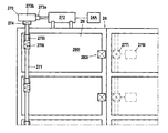
FIG. 1 schematically depicts the electronic locker system according to at least one embodiment of the invention;
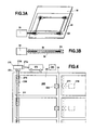
FIG. 2 is a perspective view of a compartment of an electronic locker unit in accordance with at least one embodiment of the invention;
FIG. 3A and FIG. 3B are schematic top and side views of weighing means associated with the compartment of FIG. 2; and
FIG. 4 schematically illustrates in broad outline the door closure device according to at least one embodiment of the invention.
DETAILED DESCRIPTION OF PREFERRED EMBODIMENT
In a preferred embodiment of the invention represented on FIG. 1, a secure locker system 2 comprises a communication network 10 linking at least a sender computer 20, a managing distribution centre 22, at least an electronic locker unit 24 and at least a recipient computer 26. The secure locker system is generally controlled by computer means (e.g., controller, processor) 24B associated with nontransitory computer- or processor readable media that stores information (e.g., database) 24A interfacing with electronics and mechanical structures to operate the electronic locker unit through all its input and output modes.
The electronic locker unit typically comprises a series of available compartments 28 i of different sizes and a set 30 of monitor, scanner and keyboard or touchscreen. Each compartment comprises an automatic door and an indicator 29 i, for example a display or luminous sign, a light, a speaker or a buzzer. The bottom of the electronic locker unit is preferably assigned to heavy or bulky shipments. The luminous (e.g., flashing light) or audio (e.g., beep) indication is based on predefined preferences such as the closest position available to the delivery agent, and preferably at the bottom of the electronic locker unit when the shipment is determined as bulky or heavy.
FIG. 2 illustrates a compartment for depositing a shipment such as a parcel or package 40. For tracking purposes, the parcel bears a standard identifier 42 of any kind such as a machine-readable symbol (e.g., barcode) and/or a wireless transponder (e.g., RFID tag). Each compartment comprises at least a weighing device (e.g., scale, load cell) 50. In a particular embodiment, each compartment can also comprise a presence detector 60 to detect or verify the presence or absence of the shipment. This presence detector 60 can be for instance take the form of one or more of an ultrasound emitter and sensor, infrared emitter and sensor or image acquisition device or sensor (e.g., CCD array). With this weight or presence detector located inside the compartment it is possible to know at any time whether the compartment is empty or not. As illustrated on FIGS. 3A and 3B, each weighing device comprises preferably a series of thin force sensors 52 i linked together to a circuit board 54, attached to a lower base 56, and located under an upper bearing plate 58.
For securely controlling the retrieval of shipments on at least an electronic locker unit 24 connected to the managing distribution centre 22 through the communication network 10, and having several lockable compartments 28 i, the following actions are executed at the electronic locker unit: entering identification codes of the shipment 40 for instance manually via a keypad or wirelessly via a transponder or smartphone; opening a lockable compartment of the electronic locker unit; withdrawing the shipment from the lockable compartment; checking with the processing module 24B and a weight 50 or presence detector 60 located inside the lockable compartment whether this latter is empty; closing the compartment and logging the particular lockable compartment as being emptied and successfully locked upon validation of no weight or presence detection.
The identification code of the shipment is for example an unique identifier of the shipment, a code generated at the deposit and sent to the recipient or a personal password of the recipient.
According to at least one aspect of the invention, the closing of the compartment is performed automatically by an automatic built-in closing mechanism 270 if the compartment still remains empty after a determined adjustable timeout.
As shown on FIG. 4, the automatic built-in closing mechanism 270 comprises, for example:
-
- a common pivoting shaft 271 that is driven by a unique motor 272 and a set of intermediate gear wheels 273 a, 273 b and electromagnetic clutch 274 for controlling the doors 280 i of a series of lockable compartments 28 i pertaining to a same block of the locker unit; and
- a set of freewheel 275 i (overrunning clutch) and overload clutch 276 i (safety or slip clutch) which is mounted on the common pivoting shaft 271 as a hinge for each door 280 i of the series of lockable compartments 28 i.
Each lockable compartment 28 i presents a door 280 i that can be kept in the closed position by a conventional lock assembly 282 i with a high degree of anti-tampering protection. This lock is an automated releasable locking assembly connected to the controller 24B and comprised as well known in the art and consequently not detailed here, of a lock housing, a spring-loaded lock hook or bolt, a spring-loaded lock latch, a spring-loaded lock pawl, a lock electromagnet, and position sensors.
The electronic locker unit with its door closing device operates as follows.
At a standstill, the common pivoting shaft 271 which is not driven by the motor 272, intermediate gear wheels 273 a, 273 b and electromagnetic clutch 274, can freely rotate. In operation the freewheel 275 i can drive the associated door 280 i when the common pivoting shaft 271 rotates according to the closing direction of the door. Once the door is closed and locked, if the common pivoting shaft goes on rotating, the overload clutch 276 i (torque limiter) is going to slide assisting the common pivoting shaft 271 to continue rotating.
When the controller 24B of the electric locker apparatus unlocks the door 28 i, the springs associated with bolt or hook, latch, pawl and electromagnet of lock 282 i cooperate for automatically open the door with a forward thrust. In this door configuration, the common pivoting shaft 271 rotates freely as the electromagnetic clutch 274 is inactivated. The freewheel 275 i drives the rotating common pivoting shaft while the other freewheels of the relevant series of lockable compartments behave as simple bearings. The unlocked door 280 i therefore opens under the spring forward thrust.
When the user or delivery agent intends to close the door, he/she has simply to push it to the locking position. The freewheel 275 i is then in the bearing mode for providing an effortless closing move.
When the user poorly closes the door of the lockable compartment or simply forgets to do it in spite of a prompt message and/or flashing sign highlighted and/or beep emitted for example through the indicator 29 i, it is still possible to secure the electronic locker unit with the automatic closing operation after a determined adjustable timeout, adjustable for example from thirty seconds to one minute. Thus, when at least one door 280 i remains open after retrieval of a parcel, the controller 24B starts the motor 272 that activates the electromagnetic clutch 274 and drives the common pivoting shaft 271. This shaft then rotates in the direction of closure for closing the at least one door 280 i through the associated freewheel 275 i which is in the blocking direction. The at least one open door which is controlled by the shaft is therefore driven to its final locking position defined by the automated releasable locking assembly 282 i. When several doors are open the rotation of the common pivoting shaft 271 simultaneously closes all these open doors. The rotation of the unique motor 272 is stopped by the controller 24B when the last open door is closed (i.e., the door having the largest opening).
On the other hand, the freewheel 275 i associated with a door 280 i already closed is also driven by the common pivoting shaft 271 but its associated overload clutch 276 i enables the rotation of the shaft without any move of the door, which remains closed. As soon as the at least one open door 280 i is closed and locked, the motor 272 stops and the electromagnetic clutch 274 is disconnected from the common pivoting shaft 271 which returns to its free rotation mode.
In the embodiment described above, the automatic built-in closing mechanism 27 comprises an arrangement of a motorized shaft with a clutch of any type (e.g., electromagnetic, gear, friction, plate, ratchet, cone), freewheels and overload clutches. However, those skilled in the art will recognize from the teaching herein that another closing arrangement may comprise a set made of a motor 278 i and a clutch 277 i of any type (e.g., electromagnetic, gear, friction, plate, ratchet, cone) associated with each door 280 i. In another not illustrated embodiment the unique motor 272 could also drive several common pivoting shafts with a set of a shared endless belt or rack and pinion (not described here), intermediate gear wheels and electromagnetic clutches.
The various embodiments described above can be combined to provide further embodiments. All of the commonly assigned US patent application publications, US patent applications, foreign patents, foreign patent applications and non-patent publications referred to in this specification and/or listed in the Application Data Sheet, including but not limited to European Patent Application No. 15306840.8, filed Nov. 19, 2015 are incorporated herein by reference, in their entirety.