US10113747B2 - Systems and methods for control of combustion dynamics in combustion system - Google Patents
Systems and methods for control of combustion dynamics in combustion system Download PDFInfo
- Publication number
- US10113747B2 US10113747B2 US14/687,866 US201514687866A US10113747B2 US 10113747 B2 US10113747 B2 US 10113747B2 US 201514687866 A US201514687866 A US 201514687866A US 10113747 B2 US10113747 B2 US 10113747B2
- Authority
- US
- United States
- Prior art keywords
- fuel
- orifice
- combustor
- conduit
- geometry
- Prior art date
- Legal status (The legal status is an assumption and is not a legal conclusion. Google has not performed a legal analysis and makes no representation as to the accuracy of the status listed.)
- Active, expires
Links
Images


Classifications
-
- F—MECHANICAL ENGINEERING; LIGHTING; HEATING; WEAPONS; BLASTING
- F23—COMBUSTION APPARATUS; COMBUSTION PROCESSES
- F23R—GENERATING COMBUSTION PRODUCTS OF HIGH PRESSURE OR HIGH VELOCITY, e.g. GAS-TURBINE COMBUSTION CHAMBERS
- F23R3/00—Continuous combustion chambers using liquid or gaseous fuel
- F23R3/28—Continuous combustion chambers using liquid or gaseous fuel characterised by the fuel supply
- F23R3/36—Supply of different fuels
-
- F—MECHANICAL ENGINEERING; LIGHTING; HEATING; WEAPONS; BLASTING
- F23—COMBUSTION APPARATUS; COMBUSTION PROCESSES
- F23R—GENERATING COMBUSTION PRODUCTS OF HIGH PRESSURE OR HIGH VELOCITY, e.g. GAS-TURBINE COMBUSTION CHAMBERS
- F23R3/00—Continuous combustion chambers using liquid or gaseous fuel
- F23R3/28—Continuous combustion chambers using liquid or gaseous fuel characterised by the fuel supply
-
- F—MECHANICAL ENGINEERING; LIGHTING; HEATING; WEAPONS; BLASTING
- F02—COMBUSTION ENGINES; HOT-GAS OR COMBUSTION-PRODUCT ENGINE PLANTS
- F02C—GAS-TURBINE PLANTS; AIR INTAKES FOR JET-PROPULSION PLANTS; CONTROLLING FUEL SUPPLY IN AIR-BREATHING JET-PROPULSION PLANTS
- F02C3/00—Gas-turbine plants characterised by the use of combustion products as the working fluid
- F02C3/14—Gas-turbine plants characterised by the use of combustion products as the working fluid characterised by the arrangement of the combustion chamber in the plant
-
- F—MECHANICAL ENGINEERING; LIGHTING; HEATING; WEAPONS; BLASTING
- F23—COMBUSTION APPARATUS; COMBUSTION PROCESSES
- F23N—REGULATING OR CONTROLLING COMBUSTION
- F23N5/00—Systems for controlling combustion
- F23N5/24—Preventing development of abnormal or undesired conditions, i.e. safety arrangements
- F23N5/247—Preventing development of abnormal or undesired conditions, i.e. safety arrangements using mechanical means
-
- F—MECHANICAL ENGINEERING; LIGHTING; HEATING; WEAPONS; BLASTING
- F23—COMBUSTION APPARATUS; COMBUSTION PROCESSES
- F23R—GENERATING COMBUSTION PRODUCTS OF HIGH PRESSURE OR HIGH VELOCITY, e.g. GAS-TURBINE COMBUSTION CHAMBERS
- F23R3/00—Continuous combustion chambers using liquid or gaseous fuel
- F23R3/02—Continuous combustion chambers using liquid or gaseous fuel characterised by the air-flow or gas-flow configuration
- F23R3/16—Continuous combustion chambers using liquid or gaseous fuel characterised by the air-flow or gas-flow configuration with devices inside the flame tube or the combustion chamber to influence the air or gas flow
- F23R3/18—Flame stabilising means, e.g. flame holders for after-burners of jet-propulsion plants
- F23R3/20—Flame stabilising means, e.g. flame holders for after-burners of jet-propulsion plants incorporating fuel injection means
-
- F—MECHANICAL ENGINEERING; LIGHTING; HEATING; WEAPONS; BLASTING
- F23—COMBUSTION APPARATUS; COMBUSTION PROCESSES
- F23R—GENERATING COMBUSTION PRODUCTS OF HIGH PRESSURE OR HIGH VELOCITY, e.g. GAS-TURBINE COMBUSTION CHAMBERS
- F23R3/00—Continuous combustion chambers using liquid or gaseous fuel
- F23R3/28—Continuous combustion chambers using liquid or gaseous fuel characterised by the fuel supply
- F23R3/34—Feeding into different combustion zones
-
- F—MECHANICAL ENGINEERING; LIGHTING; HEATING; WEAPONS; BLASTING
- F23—COMBUSTION APPARATUS; COMBUSTION PROCESSES
- F23R—GENERATING COMBUSTION PRODUCTS OF HIGH PRESSURE OR HIGH VELOCITY, e.g. GAS-TURBINE COMBUSTION CHAMBERS
- F23R3/00—Continuous combustion chambers using liquid or gaseous fuel
- F23R3/42—Continuous combustion chambers using liquid or gaseous fuel characterised by the arrangement or form of the flame tubes or combustion chambers
- F23R3/44—Combustion chambers comprising a single tubular flame tube within a tubular casing
-
- F—MECHANICAL ENGINEERING; LIGHTING; HEATING; WEAPONS; BLASTING
- F05—INDEXING SCHEMES RELATING TO ENGINES OR PUMPS IN VARIOUS SUBCLASSES OF CLASSES F01-F04
- F05D—INDEXING SCHEME FOR ASPECTS RELATING TO NON-POSITIVE-DISPLACEMENT MACHINES OR ENGINES, GAS-TURBINES OR JET-PROPULSION PLANTS
- F05D2240/00—Components
- F05D2240/35—Combustors or associated equipment
-
- F—MECHANICAL ENGINEERING; LIGHTING; HEATING; WEAPONS; BLASTING
- F05—INDEXING SCHEMES RELATING TO ENGINES OR PUMPS IN VARIOUS SUBCLASSES OF CLASSES F01-F04
- F05D—INDEXING SCHEME FOR ASPECTS RELATING TO NON-POSITIVE-DISPLACEMENT MACHINES OR ENGINES, GAS-TURBINES OR JET-PROPULSION PLANTS
- F05D2260/00—Function
- F05D2260/96—Preventing, counteracting or reducing vibration or noise
- F05D2260/964—Preventing, counteracting or reducing vibration or noise counteracting thermoacoustic noise
-
- F—MECHANICAL ENGINEERING; LIGHTING; HEATING; WEAPONS; BLASTING
- F23—COMBUSTION APPARATUS; COMBUSTION PROCESSES
- F23R—GENERATING COMBUSTION PRODUCTS OF HIGH PRESSURE OR HIGH VELOCITY, e.g. GAS-TURBINE COMBUSTION CHAMBERS
- F23R2900/00—Special features of, or arrangements for continuous combustion chambers; Combustion processes therefor
- F23R2900/00014—Reducing thermo-acoustic vibrations by passive means, e.g. by Helmholtz resonators
Definitions
- the subject matter disclosed herein relates generally to gas turbine systems, and more particularly, to systems and methods for reducing combustion dynamics, and more specifically, for reducing modal coupling of combustion dynamics within a gas turbine engine.
- Gas turbine systems generally include a gas turbine engine having a compressor section, a combustor section, and a turbine section.
- the combustor section may include one or more combustors (e.g., combustion cans), each combustor having a primary combustion system and a secondary combustion system (e.g., late lean injection (LLI) system) downstream from the primary combustion system.
- combustors e.g., combustion cans
- each combustor having a primary combustion system and a secondary combustion system (e.g., late lean injection (LLI) system) downstream from the primary combustion system.
- LLI late lean injection
- a fuel and/or air mixture may be routed into the primary and secondary combustion systems through fuel nozzles, and each combustion system may be configured to combust the mixture of the fuel and air to generate hot combustion gases that drive one or more turbine stages in the turbine section.
- the generation of the hot combustion gases can create a variety of combustion dynamics, which occur when the combustor acoustic oscillations interact with the flame dynamics (also known as the oscillating component of the heat release), to result in a self-sustaining pressure oscillation in the combustor.
- Combustion dynamics can occur at multiple discrete frequencies or across a range of frequencies, and can travel both upstream and downstream relative to the respective combustor.
- the pressure waves may travel downstream into the turbine section, e.g., through one or more turbine stages, or upstream into the fuel system.
- Certain components of the turbine system can potentially respond to the combustion dynamics, particularly if the combustion dynamics generated by the individual combustors exhibit an in-phase and coherent relationship with each other, and have frequencies at or near the natural or resonant frequencies of the components.
- combustion dynamics refers to the strength of the linear relationship between two dynamic signals, and is strongly influenced by the degree of frequency overlap between them.
- coherence is a measure of the modal coupling, or combustor-to-combustor acoustic interaction, exhibited by the combustion system.
- a system in a first embodiment, includes a gas turbine engine.
- the gas turbine engine includes a first combustor having a first fuel injector and a second combustor having a second fuel injector.
- the gas turbine engine further includes a first fuel conduit extending from a first orifice to a first fuel outlet of the first fuel injector.
- the first fuel conduit has a first acoustic volume between the first orifice and the first fuel outlet.
- the gas turbine engine further includes a second fuel conduit extending from a second orifice to a second fuel outlet of the second fuel injector.
- the second fuel conduit has a second acoustic volume between the second orifice and the second fuel outlet, and the first acoustic volume and the second acoustic volume are different from one another.
- a system in a second embodiment, includes a first combustor of a gas turbine system.
- the first combustor includes a first fuel injector having a first fuel outlet and a second fuel injector having a second fuel outlet.
- the first combustor further includes the first fuel conduit extending from a first orifice to the first fuel outlet of the first fuel injector.
- the first fuel conduit has a first conduit geometry between the first orifice and the first fuel outlet and the first orifice has a first orifice geometry.
- the first combustor further includes a second fuel conduit extending from a second orifice to the second fuel outlet of the second fuel injector.
- the second fuel conduit has a second conduit geometry between the second orifice and the second fuel outlet and the second orifice has a second orifice geometry.
- the first conduit geometry and the second conduit geometry are different from one another, or the first orifice geometry and the second orifice geometry are different from one another, or a combination thereof.
- a system in a third embodiment, includes a first fuel conduit extending from a first orifice to a first fuel outlet of a first fuel injector of a gas turbine engine.
- the first fuel conduit has a first conduit geometry between the first orifice and the first fuel outlet, and the first orifice has a first orifice geometry.
- the system further includes a second fuel conduit extending from a second orifice to a second fuel outlet of a second fuel injector of the gas turbine engine.
- the second fuel conduit has a second conduit geometry between the second orifice and the second fuel outlet.
- the second orifice has a second orifice geometry different from the first orifice geometry, or the second conduit geometry is different from the first conduit geometry.
- FIG. 1 is a schematic of an embodiment of a gas turbine system having a plurality of combustors, where each combustor is equipped with a late lean injection (LLI) fuel circuit;
- LLI late lean injection
- FIG. 2 is a schematic of an embodiment of one of the combustors of FIG. 1 , including one or more fuel lines within the LLI fuel circuit, where the position of a pre-orifice within each fuel line varies from one fuel line to another to help control combustion dynamics and/or modal coupling of combustion dynamics to reduce the possibility of unwanted vibratory responses in downstream components;
- FIG. 3 is a cross-sectional schematic of an embodiment of a cross-sectional view of the combustor of FIG. 2 , taken along line 3 - 3 , illustrating the one or more fuel lines configured to route a secondary fuel from the pre-orifice to a post-orifice;
- FIG. 4 is a schematic of an embodiment of the gas turbine system of FIG. 1 , illustrating a plurality of combustors each having one or more fuel supply systems;
- FIG. 5 is a schematic of an embodiment of two fuel supply systems coupled to a combustor of FIG. 4 ;
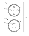
- FIG. 6 is a schematic of an embodiment of pre-orifices (e.g., a first pre-orifice and a second pre-orifice) of the two fuel supply systems of FIG. 5 ;
- pre-orifices e.g., a first pre-orifice and a second pre-orifice
- FIG. 7 is a schematic of an embodiment of a first fuel supply system and a second fuel supply system coupled to a first combustor of FIG. 4 and a third fuel supply system and a fourth fuel supply system coupled to a second combustor of FIG. 4 ;
- FIG. 8 is a schematic of an embodiment of exemplary pre-orifices, as may be associated with the first fuel supply system and the third fuel supply system of FIG. 7 .
- a gas turbine combustor (or combustor assembly) may generate combustion dynamics due to the combustion process, characteristics of intake fluid flows (e.g., fuel, oxidant, diluent, etc.) into the combustor, and various other factors.
- the combustion dynamics may be characterized as pressure fluctuations, pulsations, oscillations, and/or waves at certain frequencies.
- the fluid flow characteristics may include velocity, pressure, fluctuations in velocity and/or pressure, variations in flow paths (e.g., turns, shapes, interruptions, etc.), or any combination thereof.
- the combustion dynamics can potentially cause vibratory responses and/or resonant behavior in various components upstream and/or downstream from the combustor, as well as the combustors themselves.
- the combustion dynamics e.g., at certain frequencies, ranges of frequencies, amplitudes, combustor-to-combustor phases, etc.
- the combustion dynamics can travel both upstream and downstream in the gas turbine system. If the gas turbine combustors, upstream components, and/or downstream components have natural or resonant frequencies that are driven by these pressure fluctuations (i.e. combustion dynamics), then the pressure fluctuations can potentially cause vibration, stress, fatigue, etc.
- the components may include combustor liners, combustor flow sleeves, combustor caps, fuel nozzles, turbine nozzles, turbine blades, turbine shrouds, turbine wheels, bearings, fuel supply assemblies, or any combination thereof.
- the downstream components are of specific interest, as they are more sensitive to combustion tones that are in-phase and coherent. Thus, reducing coherence, altering phase and/or reducing the amplitudes of the combustion dynamics specifically reduces the possibility of unwanted vibrations in downstream components.
- One way to reduce the coherence of the combustion dynamics among the combustors is to alter the frequency relationship between two or more combustors, diminishing any combustor-to-combustor coupling.
- modal coupling of combustion dynamics is reduced, which, in turn, reduces the ability of the combustor tone to cause a vibratory response in downstream components.
- An alternate method of reducing modal coupling is to reduce the constructive interference of the fuel nozzles within the same combustor, by introduction of a phase delay between the fuel nozzles, reducing the amplitudes in each combustor, and potentially preventing or reducing combustor-to-combustor coupling.
- introducing a phase lag between the combustors, or otherwise altering the phase relationship between two or more combustors may also help to prevent or reduce unwanted vibrations in the gas turbine system.
- the disclosed embodiments may vary the physical characteristics of a pre-orifice within a fuel line of a fuel supply assembly (e.g., late lean injection (LLI) fuel circuit) to modify the fuel system acoustic impedance, which may lead to combustion dynamics frequencies in one or more combustors that are different, phase shifted, smeared or spread out over a greater frequency range, or any combination thereof, relative to any resonant frequencies of the components in the gas turbine system.
- a gas turbine system may include one or more combustor assemblies (e.g., combustor cans, combustors, etc.), and each combustor may be configured with a primary combustion zone and a secondary combustion zone.
- the secondary combustion zone may include an LLI fuel circuit configured to route a secondary fuel into a secondary combustion zone for combustion.
- each LLI fuel circuit includes one or more fuel lines extending along either the liner or the flow sleeve of the combustor, and each fuel line is configured to provide a secondary fuel to one or more fuel injectors that route the secondary fuel into the secondary combustion zone.
- each of the one or more LLI fuel lines may include one or more pre-orifices through which the fuel flows in the LLI fuel circuit prior to arriving at the LLI fuel nozzles, where the fuel is injected into the combustor through one or more post-orifices.
- the fuel system acoustic impedance of the fuel nozzles is defined by the geometry of the pre-orifice, the geometry of the post-orifice and the volume between the pre and post-orifice. Accordingly, varying the position of the pre-orifice within the LLI fuel circuit adjusts the volume between the pre and post orifice, to adjust the fuel system acoustic impedance of one or more fuel nozzles. In addition, altering the size, shape and/or number of holes in the pre-orifice may also alter the fuel system acoustic impedance of one or more fuel nozzles.
- the physical characteristics (e.g., position, sizing, shape, location, effective area, etc.) of the pre-orifice of each fuel line within the LLI fuel circuit of a single combustor may be different from the physical characteristics of the pre-orifice of another fuel line within the same LLI fuel circuit.
- the location of the pre-orifice along the LLI fuel line may be shifted, so that it is closer or further away from the post-orifice, thus changing the acoustic volume between the pre and post orifices, thereby altering the fuel system impedance.
- the location of the pre-orifice relative to the post-orifice may be shifted relative to other fuel lines of the same combustor, thus changing the acoustic volume between the pre and post orifices and thereby altering the fuel system impedance.
- the physical characteristics of the pre-orifices of the one or more fuel lines within a single combustor may be different from the physical characteristics of the pre-orifices of one or more fuel lines within another (e.g., adjacent, alternating) combustor within the gas turbine system.
- the location of the pre-orifice relative to the post-orifice along the LLI fuel lines of a first combustor may be shifted when compared to the location of the pre-orifice relative to the post-orifice of another combustor (e.g., an adjacent combustor), thereby changing the acoustic volume between the pre and post orifices and thus altering the fuel system impedance between different combustors within the gas turbine system.
- another combustor e.g., an adjacent combustor
- the magnitude and phase of the fuel system impedance for the fuel nozzle will be changed, which affects the fluctuating component of the heat release, and therefore the combustion dynamics of the combustor. Varying the fuel system impedance between two or more fuel lines within a combustor by varying the physical characteristics of two or more pre-orifices results in different fuel system acoustic impedance magnitudes and phases for the different fuel nozzles.
- the difference in the phase of the fuel system impedance between the fuel nozzles results in destructive interference of the heat release fluctuations associated with each of the fuel nozzles, reducing the amplitude of the combustion dynamics, and potentially smearing the frequency content of the combustion dynamics across a broader frequency range.
- the physical characteristics of the pre-orifice (e.g., location, size, position, shape, effective area, etc.) of each fuel line within a particular combustor may be the same, but may be varied compared to the pre-orifices of fuel lines within other combustors within the system. Varying the physical characteristics of the pre-orifices among the fuel lines of various combustors may vary the fuel system acoustic impedance and therefore, combustion dynamics, from combustor to combustor in a manner to reduce the combustion dynamics amplitudes, alter the combustion dynamics frequency, alter the phase of the combustion dynamics, and/or reduce modal coupling of the combustion dynamics among the plurality of gas turbine combustors.
- the physical characteristics of the pre-orifice may be varied within a particular combustor, as well as among one or more combustors of the system in order to reduce dynamic amplitudes as well as coherence within and/or among the combustors of the system.
- the physical characteristics of the pre-orifices among the combustors may be varied according to various patterns or groupings, as further explained below. Indeed, such variations may help reduce the amplitudes of the combustion dynamics and/or reduce the possibility of modal coupling of the combustors, particularly at frequencies that are aligned with resonant frequencies of the components of the gas turbine system.
- FIG. 1 is a schematic of an embodiment of a gas turbine system 10 having a plurality of combustors 12 and a fuel supply circuit 14 , such as an LLI fuel circuit 14 .
- each combustor 12 may be associated with a fuel circuit 14 that routes a liquid and/or gas fuel into the combustors 12 .
- the fuel circuit 14 may be configured to route a liquid and/or gas secondary fuel 16 (e.g., secondary fuel 16 , second fuel 16 ) to one or more fuel supply systems 18 of the combustor 12 .
- Each fuel supply system 18 of the combustor 12 includes a pre-orifice 20 disposed along a fuel conduit 22 (as illustrated in FIG.
- the secondary fuel 16 may be provided to the combustor 12 from the fuel circuit 14 . From the fuel circuit 14 , the fuel flows through the pre-orifice 20 in the fuel conduit 22 , and may be then routed through the secondary fuel nozzle 64 via one or more post-orifices 24 .
- varying the geometries of the pre-orifices 20 as described above may adjust the fuel system acoustic impedance of one or more of the secondary nozzles 64 , thereby leading to a shift in combustion dynamics frequency and/or greater variations in the frequency content of the resulting combustion dynamics, and/or reduced amplitudes of the combustion dynamics.
- the gas turbine system 10 includes the one or more combustors 12 having the fuel line systems 18 , a compressor 26 , and a turbine 28 .
- the combustors 12 include primary fuel nozzles 30 which route a primary fuel 32 (e.g., liquid fuel and/or a gas fuel, a first fuel, etc.) into the combustors 12 for combustion within the primary combustion zone.
- the combustors 12 include secondary fuel nozzles 64 (as illustrated in FIG. 2 ) which route a secondary fuel 16 into the combustors 12 for combustion within the secondary combustion zone.
- each combustor 12 is associated with the LLI fuel circuit 14 configured to provide the secondary fuel 16 to the one or more secondary fuel nozzles 64 via the one or more fuel conduits 22 .
- the combustors 12 ignite and combust an air-fuel mixture, and then the hot combustion gases 34 are passed into the turbine 28 .
- the turbine 28 includes turbine blades that are coupled to a shaft 36 , which is also coupled to several other components throughout the system 10 . As the combustion gases 34 pass through the turbine blades in the turbine 28 , the turbine 28 is driven into rotation, which causes the shaft 36 to rotate. Eventually, the combustion gases 34 exit the turbine system 10 via an exhaust outlet 38 . Further, the shaft 36 may be coupled to a load 40 , which is powered via rotation of the shaft 36 .
- the load 40 may be any suitable device that may generate power via the rotational output of the turbine system 10 , such as a power generation plant or an external mechanical load.
- the load 40 may include an electrical generator, a propeller of an airplane, and so forth.
- compressor blades are included as components of the compressor 26 .
- the blades within the compressor 26 are coupled to the shaft 36 , and will rotate as the shaft 36 is driven to rotate by the turbine 28 , as described above.
- the rotation of the blades within the compressor 26 compresses air 43 from an air intake 42 into pressurized air 44 .
- the pressurized air 44 is then fed into the primary fuel nozzles 30 of the combustors 12 .
- the primary fuel nozzles 30 mix the pressurized air 44 and fuel to produce a suitable mixture ratio for combustion (e.g., a combustion that causes the fuel to more completely burn) so as not to waste fuel or cause excess emissions.
- the physical characteristics (e.g., position, size, location, shape, effective area, etc.) of the pre-orifice 20 may vary between different fuel conduits 22 of the same combustor 12 (as shown in FIGS. 5 and 6 ), and/or may vary between different fuel conduits 22 of different combustors 12 within the same gas turbine system 10 (as shown in FIGS. 7 and 8 ).
- changing the physical characteristics of the pre-orifice 20 and/or the volume between the pre-orifice and the post-orifice 24 between different fuel conduits 22 of the same combustor 12 may help vary the fuel system acoustic impedance, and thereby help reduce unwanted vibratory responses within the combustor and/or in downstream components of the system 10 .
- changing the physical characteristics of the pre-orifice 20 and/or the volume between the pre-orifice and the post-orifice 24 between fuel conduits 22 of different combustors 12 may help vary fuel system acoustic impedances, thereby helping to reduce amplitudes and/or coherence of the combustion dynamics, and/or alter the phase of the combustion dynamics.
- changes in the physical characteristics of the pre-orifice 20 for a specific fuel nozzle may change the effective area and/or the pressure ratio for that fuel nozzle, which in turn may result in variations of the mass flow of the secondary fuel 16 entering the combustor 12 .
- the shape of the pre-orifice 20 e.g., round, oval, square, polygonal, etc.
- the shape of the pre-orifice 20 may be varied between and/or among different combustors 12 to vary the effective area and/or the pressure ratio of the pre-orifice 20 which would vary the mass flow of secondary fuel 16 entering the combustor 12 .
- shifting the location of the pre-orifice 20 relative to the post-orifice 24 may increase or decrease the acoustic volume between the pre-orifice 20 and the post-orifice 24 , thereby resulting in a phase delay between one or more secondary fuel nozzles 64 , and causing destructive interference of the equivalence ratio fluctuations generated by the fuel nozzles 64 .
- changing the physical characteristics may result in variations between the heat release of the LLI injectors within the combustor, thereby increasing the amount of temporal variation in the dynamic frequency content in the flame region, and/or increasing the destructive interference of the dynamic frequency content in the flame region, which may result in reducing the amplitude of the combustor tones and/or the coherence of the combustion dynamics.
- the size and/or shape of the pre-orifice 20 may vary between different fuel conduits 22 of the same combustor 12 (as shown in FIGS. 5 and 6 ), and/or may vary between different fuel conduits 22 of different combustors 12 within the same gas turbine system 10 (as shown in FIGS. 7 and 8 ). Further, while variations on the pre-orifice 20 are described, it should be noted that changes in the physical characteristics of the post-orifice 24 (e.g., size, shape, location, position, effective area, etc.) may also help reduce the amplitudes of the combustion dynamics within the system 10 .
- varying the physical characteristics of the fuel conduit 22 e.g., length, width, circumference, diameter, effective area, etc.
- varying the physical characteristics of the fuel conduit 22 e.g., length, width, circumference, diameter, effective area, etc.
- varying the physical characteristics of the fuel conduit 22 may help reduce unwanted vibratory responses within the gas turbine system 10 .
- FIG. 2 is a schematic view of an embodiment of one of the combustors 12 depicted in FIG. 1 , where the combustor 12 includes the fuel supply system 18 (e.g., a first fuel supply system 17 , a second fuel supply system 19 , etc.) having the pre-orifice 20 and the post-orifice 24 disposed along the fuel conduit 22 .
- the pre-orifice 20 may be disposed anywhere along the fuel conduit 22 , as illustrated in FIG. 2 .
- the physical characteristics (e.g., location, size, shape, dimensions, position) of the components of the fuel supply system 18 may be varied between different fuel supply systems 18 of the combustor 12 .
- the position of the pre-orifice 20 relative to the post-orifice 24 (and thus intermediate distance and volume) of the first fuel supply system 17 may be different than the position of the pre-orifice 20 (and thus intermediate distance and volume) relative to the post-orifice 24 of the second fuel supply system 19 , as described in detail below.
- Such variations may vary the fuel system acoustic impedance of the associated secondary fuel nozzles 64 leading to combustion dynamics frequencies that are different and/or phase-shifted between the fuel nozzles 64 and/or between combustors 12 , thereby reducing unwanted vibratory responses in the gas turbine system 10 .
- maximum destructive interference between the fuel nozzles 64 occurs when the phase delay between the fuel nozzles 64 is approximately 180 degrees.
- the combustor 12 includes a head end 50 having an end cover 52 , a combustor cap assembly 54 , and a primary combustion zone 56 .
- the end cover 52 and the combustor cap assembly 54 may be configured to support the primary fuel nozzles 30 in the head end 50 .
- the primary fuel nozzles 30 route the primary fuel 32 to the primary combustion zone 56 .
- the combustor 12 includes an outer wall (e.g., flow sleeve 68 ) disposed circumferentially about an inner wall (e.g., combustion liner 66 ).
- the inner wall may also include a transition piece 69 , which generally converges towards a first stage of the turbine 28 .
- An impingement sleeve 67 is disposed circumferentially about the transition piece 69 .
- the primary fuel nozzles 30 receive the pressurized air 44 from the annulus 58 (e.g., between transition piece 69 and impingement sleeve 67 and between liner 66 and flow sleeve 68 ) of the combustor 12 and combine the pressurized air 44 with the primary fuel 32 to form an air/fuel mixture that is ignited and combusted in the primary combustion zone 56 to form combustion gases (e.g., exhaust).
- combustion gases e.g., exhaust
- the combustion gases flow in a direction 60 to a secondary combustion zone 62 .
- the LLI fuel circuit 14 provides the secondary fuel 16 which flows through the pre-orifice 20 in the fuel conduit 22 to the post-orifice 24 .
- the post-orifice 24 in the secondary fuel nozzles 64 receive the secondary fuel 16 from the fuel conduit 22 , and route the secondary fuel 16 into the secondary combustion zone 62 to the stream of combustion gases.
- the secondary fuel nozzles 64 may receive the pressurized air 44 from the annulus 58 of the combustor 12 and combine the pressurized air 44 with the secondary fuel 16 to form an air/fuel mixture that is ignited and combusted in the secondary combustion zone 62 to form the combustion gases.
- the pressurized air 44 flows through the annulus 58 between a transition piece 69 and an impingement sleeve 67 , and then between a liner 66 and a flow sleeve 68 of the combustor 12 to reach the head end 50 .
- the combustion gases flow in the direction 60 through the transition piece 69 of the combustor 12 , and pass into the turbine 28 , as noted above.
- combustion dynamics e.g., generation of hot combustion gases
- combustion dynamics within the primary combustion zone 56 and the secondary combustion zone 62 may lead to unwanted vibratory responses within the combustor 12 .
- varying the physical characteristics of the pre-orifice within and/or among the combustors 12 may help reduce vibratory responses in the gas turbine system 10 , and minimize vibrational stress, wearing, performance degradation, or other undesirable impacts to the components of the gas turbine system 10 (e.g., turbine blades, turbine shrouds, turbine nozzles, exhaust components, combustor transition piece, combustor liner, etc.).
- the position of the pre-orifice 20 relative to the post-orifice 24 may be varied between the fuel supply systems 18 of the combustor 12 , such that the pre-orifice 20 is shifted along the fuel conduit 22 to be closer to or further away from the post-orifice 24 and the secondary fuel nozzles 64 .
- a first distance 72 between the pre-orifice 20 and the post-orifice 24 of the first fuel supply system 17 may be different (e.g., longer, shorter, greater, smaller, etc.) than a second distance 74 between the pre-orifice 20 and the post-orifice 24 of the second fuel supply system 19 .
- the distances may vary or may be configured to vary based on the location where the pre-orifice 20 is disposed along the fuel conduit 22 .
- varying the distance 72 , 74 between the pre-orifice 20 and the post-orifice 24 may be done by increasing or decreasing the length of the fuel conduit 22 upstream and downstream of the pre-orifice via one or more sections of flanged tubing.
- the length of the fuel conduits 22 may be the same between the fuel supply systems 18 , but the location of the pre-orifices 20 disposed along the fuel conduit 22 may vary between the fuel supply systems 28 .
- varying the distance (e.g., the first distance 72 and the second distance 74 of the pre-orifice 20 relative to the post-orifice 24 ) between the fuel supply systems 18 may result in phase delays between the fuel supply systems 18 , leading to destructive interference of the heat release fluctuations of the fuel nozzles 64 associated with each fuel supply system 18 , thereby reducing the amplitude of the combustor tones and possibly the coherence of the combustion dynamics.
- physical characteristics e.g., position, location, size, shape, dimensions, effective area, etc.
- physical characteristics e.g., position, location, size, shape, dimensions, effective area, etc.
- the size and/or effective area of the pre-orifice 20 or the post-orifice 24 may vary between the fuel supply systems 18 .
- the pre-orifice 20 and the post-orifice 24 may be an array or pattern of holes.
- the size, the shape, the pattern and/or arrangement of the pre-orifice 20 holes and the post-orifice 24 holes may vary between different fuel conduits 22 of the combustor 12 .
- the pre-orifice 20 and/or the post-orifice 24 may vary among the plurality of combustors 12 (e.g., 2, 3, 4, 5, 6, 7, 8, 9, 10, or more combustors 12 ) with different diameters, shapes, sizes, etc.
- the physical characteristics of the fuel conduit 22 may also vary between different fuel conduits 22 of the combustor 12 .
- the disclosed embodiments may also vary the diameter of the fuel conduit 22 , and so forth.
- one or more physical characteristics of the disclosed embodiments also may vary each component within the fuel supply system 18 between different fuel supply systems 18 of the combustor 12 , such that the combustion dynamics at each secondary fuel nozzle 64 are different (in terms of phase and/or frequency) to help reduce unwanted vibratory responses within the gas turbine system 10 .
- the dynamic amplitudes as well as coherence may be reduced between different combustors 12 of the system 10 by varying the physical characteristics of the pre-orifices among the combustors 12 , as further described with respect to FIG. 4 .
- the position of the pre-orifice 22 relative to the post-orifice 24 may be the same among the fuel supply systems 18 of a single combustor 12
- the position of the pre-orifice 22 relative to the post-orifice 24 may be varied between fuel supply systems 18 of different combustors 12 within the system 10 .
- the physical characteristics (e.g., size, position, shape, location, dimensions, effective area, etc.) of the components of the fuel supply system 18 may vary between different combustors 12 of the system 10 .
- the physical characteristics of the components of the fuel supply system 28 may vary between fuel lines 18 of the same combustor 12 , as well as between fuel lines 18 of different combustors 12 .
- FIG. 3 is a cross-sectional view of an embodiment of the combustor 12 depicted in FIG. 2 , illustrating one or more fuel supply systems 18 each receiving the secondary fuel 16 .
- the secondary fuel 16 is routed through the pre-orifice 20 , through the fuel conduit 22 , and then through the post-orifice 24 , of the secondary fuel nozzles 64 (as illustrated in FIG. 2 ).
- the fuel conduits 22 composed of one or more sections of flanged tubing, extend along the outside of the flow sleeve 68 of the combustor 12 , as illustrated in FIG. 2 , such that the fuel conduits 22 route the secondary fuel 16 from the pre-orifice 20 to the one or more secondary fuel nozzles 64 . While the illustrated embodiment depicts the fuel conduits 22 with alternating large and small diameters, as further explained below, it should be noted that in other embodiments, the fuel conduits 22 may have any sized diameters.
- the physical characteristics of the components of each fuel supply system 18 within the combustor 12 may vary, such that the size, shape, dimensions, configuration, position, location, and so forth, are different between the fuel supply systems 18 of a single combustor 12 and/or between adjacent combustors 12 .
- the size of the pre-orifice 20 and the fuel conduit 22 is different for each adjacent fuel supply system 18 .
- a first diameter 78 of the fuel conduit 22 of the first fuel supply system 17 is greater than a second diameter 80 of the fuel conduit 22 of the second fuel supply system 19 .
- any combination and/or pattern of fuel supply systems 18 may have variations in the physical characteristics of the components of the fuel supply systems 18 . Further, there may be one or more physical characteristics variations between any two fuel supply systems 18 .
- the illustrated embodiment depicts fuel conduits 22 that alternate between the first diameter 78 and the second diameter 80 . In other embodiments, the diameter size of the fuel conduits 22 may alternate between 2, 3, 4, 5, 6, 7, 8, 9, 10 or more different sizes, shapes, etc.
- FIG. 4 is a schematic of an embodiment of the gas turbine system 10 of FIG. 1 , depicting a plurality of combustors 12 each having one or more fuel supply systems 18 .
- each fuel supply system 18 includes various components such as the pre-orifice 20 , the fuel conduit 22 , and the post-orifice 24 , and the physical characteristics (e.g., size, position, dimensions, location, shape, geometric characteristics, etc.) of one or more components of the fuel supply system 18 may vary within and/or between the one or more combustors 12 of the system 10 .
- variations within the components of the fuel supply systems 18 of a single combustor 12 and/or between the components of fuel supply systems 18 of one or more combustors 12 result in changes to the fuel system acoustic impedance for one or more fuel nozzles 64 , thereby leading to a shift in combustion dynamics frequency and/or greater variations in the frequency content of the resulting combustion dynamics, and/or reduced amplitudes of the combustion dynamics, and/or differences in phase of the combustion dynamics between two or more combustors 12 .
- the illustrated embodiment depicts the variations of the fuel supply systems 18 within the combustor 12 and/or between combustors 12 .
- the gas turbine system 10 includes four combustors 12 coupled to the turbine 28 .
- the gas turbine system 10 includes any number of combustors 12 (e.g., 2, 3, 4, 5, 6, 7, 8, 9, 10, 11, 12, 13, 14, 15, 16, or more combustors).
- each combustor 12 includes the fuel circuit 14 configured to provide the secondary fuel 16 to the pre-orifice 20 positioned in the fuel conduit 22 near the head 50 of the combustor 12 . Further, the secondary fuel 16 is routed through the pre-orifice 20 , through the fuel conduit 22 , and through the post-orifice 24 .
- the post-orifice 24 is configured to route the secondary fuel 16 from the secondary fuel nozzle 64 , into the secondary combustion zone 62 .
- combustors 12 ignite and combust the air-fuel mixture (e.g., the secondary fuel 16 and/or compressed air 44 ), and then the hot combustion gases 34 are passed into the turbine 28 .
- the combustion gases 34 pass through the turbine blades in the turbine 28 , various combustion dynamics may produce unwanted vibratory responses.
- the components of the fuel supply system 18 within the combustor 12 have variability among other components of the fuel supply system 18 within the same combustor 12 .
- the first distance 72 (and thereby the acoustic volume) between the pre-orifice 20 and the post-orifice 24 of the first fuel supply system 17 is greater than a second distance 74 (and thereby the acoustic volume) between the pre-orifice 20 and the post-orifice 24 of the second fuel supply system 19 .
- the pre-orifice 20 is shifted along the fuel conduit 22 so that it is closer or further away from the post-orifice 24 .
- varying the distance between the pre-orifice 20 and the post-orifice 24 varies the acoustic volume between the pre-orifice 20 and the post orifice 24 , and may be done by increasing or decreasing the length (and/or diameter) of one or more sections of tubing (e.g. flanged tubing), making up the fuel conduit 22 .
- the pre-orifice 20 can be contained between the flanges (e.g. sandwich plate), or embedded as part of one of the sections of tubing.
- varying the acoustic volume among different fuel supply systems 18 within the same combustor (e.g., the first combustor 75 ) may help to vary the fuel system impedance between the combustors 12 .
- the combustor 12 may have variability among other fuel supply system 18 components, such as the size and/or shape and/or effective areas of the pre-orifice 20 or the post-orifice 24 , the length of the fuel conduit 22 , the diameter of the fuel conduit 22 , the volume of the fuel conduit 22 , the construction material of the components of the fuel supply systems 18 , and so forth.
- the components of the fuel supply system 18 within the combustor 12 may have variability compared to the components of the fuel supply systems 18 among other combustors 12 within the system 10 (as shown in FIGS. 4, 7, and 8 .
- the physical characteristics of the components (e.g., the pre-orifice 20 , the fuel conduit 22 , the post-orifice 24 ) of the fuel supply systems 18 of the second combustor 77 may be substantially similar, in some embodiments, the physical characteristics of the components of the fuel supply systems 18 of the second combustor 77 may be different from the physical characteristics of the fuel supply systems 18 of the first combustor 75 (e.g., the first fuel supply system 17 and/or the second fuel supply system 19 ), and the physical characteristics of the components of the fuel supply system 18 of the third combustor 79 may be different from the physical characteristics of the fuel supply systems 18 of the first combustor 75 and/or the second combustor 77 as in FIGS.
- the distance of the pre-orifice 20 relative to the post-orifice 24 of the second combustor 77 may be different between one or more fuel supply systems 18 of the second combustor 77 .
- the position of the pre-orifice 20 along the fuel conduit 22 relative to the post-orifice 24 may be different between the fuel supply systems 18 of the second combustor 77 .
- the pre-orifice 20 may be disposed anywhere along the fuel conduit 22 , such that the distance between the pre-orifice 20 and the post-orifice 24 along the fuel conduit 22 may be different between fuel supply systems 18 despite having a substantially similar length fuel conduit 22 , as illustrated in the second combustor 77 . Further, the position of the pre-orifice 20 along the fuel conduit 22 relative to the post-orifice 24 (e.g., the distance between the pre-orifice 20 and the post-orifice 24 ) within the second combustor 77 is different than the first distance 72 and/or the second distance 74 within the first combustor 75 .
- the combustion dynamics and the acoustic fuel system impedance of the first combustor 75 relative to the second combustor 77 are different, thereby helping to reduce combustion dynamic amplitudes and/or possibly modal coupling of the combustion dynamics between the two combustors 12 , and/or alter the phase delay between the two combustors 12 .
- the first diameter 78 of a third fuel supply system 21 of a third combustor 79 is larger than the second diameter 80 of a fourth fuel supply system 23 of the same third combustor 79 .
- the first distance 72 of the third fuel supply system 21 is greater than the second distance 74 of the fourth fuel supply system 23 .
- the shape or physical configuration of the fuel supply systems 18 may vary within and/or between the combustors 12 . For example, in a fourth combustor 81 shown in FIG.
- the shape of the fuel conduit 22 within the fuel supply system 25 is curved convexly towards the exit 70 of the fourth combustor 81 .
- the shape of the fuel conduit 22 may include one or more angles (e.g., jagged shape), waves, rough edges, and so forth, such that the one or more tubing sections of the fuel conduit 22 is shaped differently than adjacent fuel conduits 22 within or between the combustors 12 .
- a fuel supply system 27 of the fourth combustor 81 includes a fuel conduit 22 in a wave form.
- the fuel conduits 22 may include protrusions 82 (e.g., waves, rough edges, angles, and so forth) on an inner surface 84 of the fuel conduit 22 that provides variations in the fuel flow of the secondary fuel 16 .
- the protrusions 82 may be formed from the same material as the fuel conduit 22 . As noted above, such variations of the physical characteristics between various components of the fuel supply systems 18 help to reduce the amplitudes of the combustor tones and/or the coherence of the combustion dynamics.
- FIG. 5 is a schematic of an embodiment of the third fuel supply system 21 and the fourth fuel supply system 23 of the third combustor 79 , where the third combustor 79 is illustrated in FIG. 4 .
- the illustrated embodiment depicts physical variations between the third fuel supply system 21 and the fourth fuel supply system 23 , such as variations in distance between the pre-orifice 20 and the post-orifice 24 and variations in diameter of the fuel conduit 22 .
- the first distance 72 between the pre-orifice 20 and the post-orifice 24 of the third fuel supply system 21 is greater than the second distance 74 between the pre-orifice 20 and the post-orifice 24 of the fourth fuel supply system 23 .
- first diameter 78 of the fuel conduit 22 of the third fuel supply system 21 is greater than the second diameter 80 of the fuel conduit 22 of the fourth fuel supply system 23 .
- a first acoustic volume 83 within the third fuel supply system 21 may be greater than a second acoustic volume 85 within the fourth fuel supply system 23 .
- the first acoustic volume 83 within a particular fuel supply system 18 may be different than the second acoustic volume 85 within another (e.g., adjacent) fuel supply system 18 .
- the width of the pre-orifice 20 may vary between different fuel supply systems 18 .
- a first width 86 (or diameter, cross-sectional area, shape, etc.) of the pre-orifice 20 in the third fuel supply system 21 may be greater than a second width 88 (or diameter, cross-sectional area, shape, etc.) of the pre-orifice 20 in the fourth fuel supply system 23 .
- a third width 90 (or diameter, cross-sectional area, shape, etc.) of the post-orifice 24 of the third fuel supply system 21 may be greater than a fourth width 92 (or diameter, cross-sectional area, shape, etc.) of the post-orifice 24 of the fourth fuel supply system 23 .
- the width of the pre-orifice 20 e.g., the first width 86 and/or the second width 88
- the width of the post-orifice 24 e.g., the third width 90 and/or the fourth width 92
- the fuel supply systems 18 e.g., between the fuel supply systems 21 and 23 .
- the pre-orifices 20 and/or the post-orifices 24 may have physical characteristics (e.g., shape, dimensions, holes, thickness, material, arrangement, pattern, hole shape, hole size, etc.) that are different within and/or between combustors 12 .
- a first pre-orifice 94 of the third fuel supply system 21 may be different than a second pre-orifice 96 of the fourth fuel supply system 23 , as explained further with respect to FIG. 6 .
- FIG. 6 is a schematic of an embodiment of the pre-orifices 20 of the fuel supply systems 18 .
- the pre-orifice 94 of the third fuel supply system 21 may have physical characteristics that vary from the second pre-orifice 96 of the fourth fuel supply system 23 .
- the pre-orifices 94 and 96 have differences in hole shapes and patterns, which may change the effective area and/or the pressure ratio of the mass flow of the secondary fuel 16 through the pre-orifices 94 and 96 .
- the pre-orifice 94 may include five circular holes arranged in an annular pattern around a central hole 100 .
- the pre-orifice 96 may include five triangular holes 102 arranged in an annular pattern around a central square 104 .
- any number of holes e.g., 1, 2, 3, 4, 5, 6, 7, 8, 9, 10, etc.
- any shape or pattern symmetrical, spirals, random, waves, checkered, etc.
- variations between the fuel supply systems 18 in different combustors may exist, instead of, or in addition to, differences between the fuel supply systems 18 of each combustor.
- the pre-orifice 20 has a first thickness 106 and multiple orifice holes, each having a width 116 (or diameter, cross-sectional area, shape, etc.); the fuel conduit 22 has a first diameter 126 ; the post-orifice 24 defines a first width 136 ; and a first acoustic volume 123 is defined over the distance 72 between the pre-orifice 20 and the post-orifice 24 .
- the pre-orifice 20 has a second thickness 108 and an orifice hole having a width 118 (or diameter, cross-sectional area, shape, etc.); the fuel conduit 22 has a second diameter 128 ; the post-orifice 24 defines a second width 138 ; and a second acoustic volume 133 is defined over the distance 74 between the pre-orifice 20 and the post-orifice 24 .
- the pre-orifice 20 has a third thickness 112 and an orifice hole having a width 86 (or diameter, cross-sectional area, shape, etc.); the fuel conduit 22 has a third diameter 78 ; the post-orifice 24 defines a third width 90 ; and a third acoustic volume 83 is defined over the distance 72 between the pre-orifice 20 and the post-orifice 24 .
- the pre-orifice 20 has a fourth thickness 114 and an orifice hole having a width 88 (or diameter, cross-sectional area, shape, etc.); the fuel conduit 22 has a fourth diameter 80 ; the post-orifice 24 defines a fourth width 92 ; and a fourth acoustic volume 85 is defined over the distance 74 between the pre-orifice 20 and the post-orifice 24 .
- the first fuel supply system 17 of the first combustor 75 has components that are different from the third fuel supply system 21 of the third combustor 79 (e.g., in number of orifices, width/size of pre-orifice, thickness of pre-orifice, diameter of fuel conduit, and/or width of post-orifice), even though the distance 72 between the pre-orifice 20 and the post-orifice 24 is the same.
- the second fuel supply system 19 of the first combustor 75 has components that are different from the fourth fuel supply system 23 of the third combustor 79 (e.g., in number of orifices, width/size of pre-orifice, thickness of pre-orifice, diameter of fuel conduit, and/or width of post-orifice), even though the distance 74 between the pre-orifice 20 and the post-orifice 24 is the same.
- the differences in the number of orifices and the width/size of the pre-orifices is shown schematically in FIG. 8 .
- Technical effects of the invention include reducing unwanted vibratory responses associated with combustion dynamics within or among combustors 12 of the gas turbine system 10 by varying the physical characteristics of the pre-orifice 20 within the one or more fuel supply systems 18 of the combustor 12 to adjust the fuel system acoustic impedance (magnitude and phase) within the system 10 .
- the position of the pre-orifice 20 may be shifted along the fuel conduit 22 , so that it is closer or further away from the post-orifice 24 , thereby changing the acoustic volume between the pre-orifice 20 and the post-orifice 24 .
- the physical characteristics of other components of the fuel supply systems 18 may be varied within or among the combustors 12 .
Landscapes
- Engineering & Computer Science (AREA)
- Chemical & Material Sciences (AREA)
- Combustion & Propulsion (AREA)
- Mechanical Engineering (AREA)
- General Engineering & Computer Science (AREA)
Priority Applications (5)
| Application Number | Priority Date | Filing Date | Title |
|---|---|---|---|
| US14/687,866 US10113747B2 (en) | 2015-04-15 | 2015-04-15 | Systems and methods for control of combustion dynamics in combustion system |
| JP2016079264A JP6774208B2 (ja) | 2015-04-15 | 2016-04-12 | 燃焼システム内の燃焼ダイナミックスの制御のためのシステムおよび方法 |
| GB1606510.4A GB2539082B (en) | 2015-04-15 | 2016-04-14 | Systems and methods for control of combustion dynamics in combustion system |
| CN201610459086.3A CN106196173B (zh) | 2015-04-15 | 2016-04-15 | 用于控制燃烧系统中的燃烧动态的系统和方法 |
| DE102016106984.1A DE102016106984A1 (de) | 2015-04-15 | 2016-04-15 | Systeme und Verfahren zur Steuerung der Verbrennungsdynamik in einem Verbrennungssystem |
Applications Claiming Priority (1)
| Application Number | Priority Date | Filing Date | Title |
|---|---|---|---|
| US14/687,866 US10113747B2 (en) | 2015-04-15 | 2015-04-15 | Systems and methods for control of combustion dynamics in combustion system |
Publications (2)
| Publication Number | Publication Date |
|---|---|
| US20160305337A1 US20160305337A1 (en) | 2016-10-20 |
| US10113747B2 true US10113747B2 (en) | 2018-10-30 |
Family
ID=57043852
Family Applications (1)
| Application Number | Title | Priority Date | Filing Date |
|---|---|---|---|
| US14/687,866 Active 2035-12-16 US10113747B2 (en) | 2015-04-15 | 2015-04-15 | Systems and methods for control of combustion dynamics in combustion system |
Country Status (5)
| Country | Link |
|---|---|
| US (1) | US10113747B2 (de) |
| JP (1) | JP6774208B2 (de) |
| CN (1) | CN106196173B (de) |
| DE (1) | DE102016106984A1 (de) |
| GB (1) | GB2539082B (de) |
Cited By (3)
| Publication number | Priority date | Publication date | Assignee | Title |
|---|---|---|---|---|
| US11891949B1 (en) | 2022-12-30 | 2024-02-06 | Ge Infrastructure Technology Llc | System and method having multi-fluid injectors for isothermal expansion in turbine stage of gas turbine engine |
| US11971170B1 (en) | 2022-12-30 | 2024-04-30 | Ge Infrastructure Technology Llc | System and method having flame stabilizers for isothermal expansion in turbine stage of gas turbine engine |
| US12037951B1 (en) | 2022-12-30 | 2024-07-16 | Ge Infrastructure Technology Llc | System and method having load control for isothermal expansion in turbine stage of gas turbine engine |
Families Citing this family (5)
| Publication number | Priority date | Publication date | Assignee | Title |
|---|---|---|---|---|
| US9845956B2 (en) * | 2014-04-09 | 2017-12-19 | General Electric Company | System and method for control of combustion dynamics in combustion system |
| DE102017212616A1 (de) * | 2017-07-21 | 2019-01-24 | Rolls-Royce Deutschland Ltd & Co Kg | Düsenbaugruppe für eine Brennkammer eines Triebwerks |
| US11408347B2 (en) | 2019-07-22 | 2022-08-09 | Hamilton Sundstrand Corporation | Fuel systems |
| CN111473362B (zh) * | 2020-04-14 | 2021-11-16 | 中国科学院工程热物理研究所 | 一种燃气轮机燃烧室预混喷嘴 |
| EP4019840B1 (de) * | 2020-12-24 | 2024-04-03 | Ansaldo Energia Switzerland AG | Brennkammereinheit für eine gasturbinenanordnung |
Citations (76)
| Publication number | Priority date | Publication date | Assignee | Title |
|---|---|---|---|---|
| US2072826A (en) | 1935-06-05 | 1937-03-02 | Hartford Empire Co | Article transferring mechanism |
| GB881935A (en) | 1959-09-28 | 1961-11-08 | Gen Electric | Fuel injector for a combustion chamber |
| US4044553A (en) | 1976-08-16 | 1977-08-30 | General Motors Corporation | Variable geometry swirler |
| US4620414A (en) | 1983-07-27 | 1986-11-04 | Dieter Christ | Gas turbine engine |
| US4677822A (en) | 1985-02-22 | 1987-07-07 | Hitachi, Ltd. | Gas turbine combustor |
| US4724670A (en) | 1983-01-07 | 1988-02-16 | Josie M. Greer, Administratrix | Turbine engine |
| US4901694A (en) | 1988-11-14 | 1990-02-20 | Masami Sakita | Rotary engine |
| US5159807A (en) | 1990-05-03 | 1992-11-03 | Societe Nationale D'etude Et De Construction De Motors D'aviation "S.N.E.C.M.A." | Control system for oxidizer intake diaphragms |
| US5211004A (en) | 1992-05-27 | 1993-05-18 | General Electric Company | Apparatus for reducing fuel/air concentration oscillations in gas turbine combustors |
| US5319931A (en) | 1992-12-30 | 1994-06-14 | General Electric Company | Fuel trim method for a multiple chamber gas turbine combustion system |
| US5345758A (en) | 1993-04-14 | 1994-09-13 | Adroit Systems, Inc. | Rotary valve multiple combustor pulse detonation engine |
| US5575144A (en) | 1994-11-28 | 1996-11-19 | General Electric Company | System and method for actively controlling pressure pulses in a gas turbine engine combustor |
| US5657631A (en) | 1995-03-13 | 1997-08-19 | B.B.A. Research & Development, Inc. | Injector for turbine engines |
| US5809769A (en) | 1996-11-06 | 1998-09-22 | The United States Of America As Represented By The United States Department Of Energy | Combustor oscillation attenuation via the control of fuel-supply line dynamics |
| US5943866A (en) | 1994-10-03 | 1999-08-31 | General Electric Company | Dynamically uncoupled low NOx combustor having multiple premixers with axial staging |
| US6016658A (en) | 1997-05-13 | 2000-01-25 | Capstone Turbine Corporation | Low emissions combustion system for a gas turbine engine |
| US20030144787A1 (en) | 2002-01-29 | 2003-07-31 | Davis Lewis Berkley | Performance enhanced control of dln gas turbines |
| US6625569B2 (en) | 2001-03-08 | 2003-09-23 | California Institute Of Technology | Real-time spatio-temporal coherence estimation for autonomous mode identification and invariance tracking |
| US20040083738A1 (en) | 2002-10-31 | 2004-05-06 | Mcmanus Keith | Acoustic impedance-matched fuel nozzle device and tunable fuel injection resonator assembly |
| EP1605205A2 (de) | 2004-05-28 | 2005-12-14 | General Electronic Company | Verfahren und Vorrichtung zur Vorhersage und/oder Vermeidung des Flammenverlöschens in einem Gasturbinentriebwerk |
| US20060041368A1 (en) | 2004-08-18 | 2006-02-23 | General Electric Company | Systems, Methods and Computer Program Products for Remote Monitoring of Turbine Combustion Dynamics |
| US20060042261A1 (en) | 2004-08-31 | 2006-03-02 | Taware Avinash V | Methods and apparatus for gas turbine engine lean blowout avoidance |
| US20060107666A1 (en) | 2004-11-24 | 2006-05-25 | General Electric Company | Method and apparatus for automatically actuating fuel trim valves in a gas |
| US20060254279A1 (en) | 2005-05-10 | 2006-11-16 | General Electric Company | Method of tuning individual combustion chambers in a turbine based on a combustion chamber stratification index |
| US20070180831A1 (en) | 2006-02-09 | 2007-08-09 | Siemens Power Generation, Inc. | Fuel flow tuning for a stage of a gas turbine engine |
| US20070199328A1 (en) | 2004-11-04 | 2007-08-30 | General Electric Company | System for identification of hot and cold chambers in a gas turbine combustor |
| US7320222B2 (en) | 2002-03-07 | 2008-01-22 | Siemens Aktiengesellschaft | Burner, method for operating a burner and gas turbine |
| US7331182B2 (en) | 2002-01-16 | 2008-02-19 | Alstom Technology Ltd | Combustion chamber for a gas turbine |
| US20080264033A1 (en) * | 2007-04-27 | 2008-10-30 | Benjamin Paul Lacy | METHODS AND SYSTEMS TO FACILITATE REDUCING NOx EMISSIONS IN COMBUSTION SYSTEMS |
| US20090005952A1 (en) | 2007-06-26 | 2009-01-01 | General Electric Company | Systems and Methods for Using a Combustion Dynamics Tuning Algorithm with a Multi-Can Combustor |
| US20090005951A1 (en) | 2007-06-26 | 2009-01-01 | General Electric Company | Systems and Methods for Using a Combustion Dynamics Tuning Algorithm with a Multi-Can Combustor |
| EP2031192A2 (de) | 2007-08-28 | 2009-03-04 | General Electric Company | Verfahren und System zur Erkennung von Verbrennungsausblasungen einer Gasturbine mithilfe einer kraftstoffnormalisierten Leistungsreaktion |
| US7503177B2 (en) | 2006-03-17 | 2009-03-17 | Siemens Energy, Inc. | Combustion dynamics monitoring |
| US7523614B2 (en) | 2006-02-27 | 2009-04-28 | Mitsubishi Heavy Industries, Ltd. | Combustor |
| US7578130B1 (en) | 2008-05-20 | 2009-08-25 | General Electric Company | Methods and systems for combustion dynamics reduction |
| US20090320483A1 (en) | 2008-06-26 | 2009-12-31 | General Electric Company | Variable Orifice Plug for Turbine Fuel Nozzle |
| US7693147B2 (en) | 2003-04-04 | 2010-04-06 | General Electric Company | Method and apparatus for remotely monitoring gas turbine combustion dynamics |
| US7739999B2 (en) | 2005-11-23 | 2010-06-22 | Gm Global Technology Operations, Inc. | Method and apparatus to control combustion in a multi-cylinder homogeneous charge compression-ignition engine |
| US20100170254A1 (en) * | 2009-01-07 | 2010-07-08 | General Electric Company | Late lean injection fuel staging configurations |
| US20100192578A1 (en) | 2009-01-30 | 2010-08-05 | General Electric Company | System and method for suppressing combustion instability in a turbomachine |
| US20100232930A1 (en) | 2009-03-16 | 2010-09-16 | Terry Lynn Gregory | Gas turbine engine |
| US20100236214A1 (en) | 2009-03-19 | 2010-09-23 | General Electric Company | Rotary air valve firing patterns for resonance detuning |
| US20100313568A1 (en) | 2009-06-16 | 2010-12-16 | General Electric Company | Resonator assembly for mitigating dynamics in gas turbines |
| US20110048022A1 (en) | 2009-08-29 | 2011-03-03 | General Electric Company | System and method for combustion dynamics control of gas turbine |
| US20110048021A1 (en) | 2009-08-31 | 2011-03-03 | General Electric Company | Acoustically stiffened gas turbine combustor supply |
| US20110072826A1 (en) | 2009-09-25 | 2011-03-31 | General Electric Company | Can to can modal decoupling using can-level fuel splits |
| US20110162370A1 (en) | 2010-01-04 | 2011-07-07 | General Electric Company | FUEL SYSTEM ACOUSTIC FEATURE TO MITIGATE COMBUSTION DYNAMICS FOR MULTI-NOZZLE DRY LOW Nox COMBUSTION SYSTEM AND METHOD |
| US20110179795A1 (en) | 2009-07-08 | 2011-07-28 | General Electric Company | Injector with integrated resonator |
| US20110308654A1 (en) | 2010-06-16 | 2011-12-22 | Mirko Bothien | Damper arrangement and method for designing same |
| US20120006029A1 (en) | 2010-07-08 | 2012-01-12 | Bilbao Juan E Portillo | Air biasing system in a gas turbine combustor |
| US8112216B2 (en) | 2009-01-07 | 2012-02-07 | General Electric Company | Late lean injection with adjustable air splits |
| US8113000B2 (en) | 2008-09-15 | 2012-02-14 | Siemens Energy, Inc. | Flashback resistant pre-mixer assembly |
| JP2012102733A (ja) | 2010-11-09 | 2012-05-31 | General Electric Co <Ge> | 燃料噴射位置における燃料流量変動の音響制御/相殺による燃焼動態制御のためのシステム及び方法 |
| US20120131923A1 (en) | 2010-11-30 | 2012-05-31 | General Electric Company | System and method for premixer wake and vortex filling for enhanced flame-holding resistance |
| US20120144832A1 (en) | 2010-12-10 | 2012-06-14 | General Electric Company | Passive air-fuel mixing prechamber |
| US20120180487A1 (en) * | 2011-01-19 | 2012-07-19 | General Electric Company | System for flow control in multi-tube fuel nozzle |
| US20130000312A1 (en) | 2011-06-30 | 2013-01-03 | General Electric Company | Turbomachine combustor assembly including a vortex modification system |
| US20130014514A1 (en) | 2011-07-14 | 2013-01-17 | Bryan Wesley Romig | Systems and methods for bulk temperature variation reduction of a gas turbine through can-to-can fuel temperature modulation |
| US20140053258A1 (en) | 2012-08-16 | 2014-02-20 | Hon Hai Precision Industry Co., Ltd. | Handheld device and method for unlocking the handheld device |
| US20140053528A1 (en) | 2012-08-21 | 2014-02-27 | General Electric Company | System and method for reducing combustion dynamics |
| US20140060063A1 (en) | 2012-09-06 | 2014-03-06 | General Electric Company | Systems and Methods For Suppressing Combustion Driven Pressure Fluctuations With a Premix Combustor Having Multiple Premix Times |
| US20140109587A1 (en) | 2012-08-21 | 2014-04-24 | General Electric Company | System and method for reducing modal coupling of combustion dynamics |
| US20140137561A1 (en) | 2012-11-19 | 2014-05-22 | General Electric Company | System and method for reducing modal coupling of combustion dynamics |
| US20140238026A1 (en) | 2013-02-27 | 2014-08-28 | General Electric Company | Fuel nozzle for reducing modal coupling of combustion dynamics |
| US20140238033A1 (en) | 2013-02-26 | 2014-08-28 | General Electric Company | Systems and Methods to Control Combustion Dynamic Frequencies |
| US20140238041A1 (en) | 2013-02-27 | 2014-08-28 | General Electric Company | Combustor can temperature control system |
| US20140260299A1 (en) | 2013-03-12 | 2014-09-18 | General Electric Company | Fuel-air mixing system for gas turbine system |
| US20140338341A1 (en) | 2012-06-22 | 2014-11-20 | Solar Turbines Incorporated | Liquid fuel turbine engine for reduced oscillations |
| US8966909B2 (en) | 2012-08-21 | 2015-03-03 | General Electric Company | System for reducing combustion dynamics |
| US9027349B2 (en) | 2011-01-27 | 2015-05-12 | Mitsubishi Hitachi Power Systems, Ltd. | Gas turbine gaseous fuel injection system |
| US20150219337A1 (en) | 2014-02-03 | 2015-08-06 | General Electric Company | System and method for reducing modal coupling of combustion dynamics |
| US20150260407A1 (en) | 2014-03-12 | 2015-09-17 | General Electric Company | System and method for control of combustion dynamics in combustion system |
| US20150285508A1 (en) | 2013-11-22 | 2015-10-08 | James Olson | Stoking and rearranging combustible matter of a fire |
| US20150292744A1 (en) | 2014-04-09 | 2015-10-15 | General Electric Company | System and method for control of combustion dynamics in combustion system |
| US20160169520A1 (en) | 2014-12-11 | 2016-06-16 | General Electric Company | Injector apparatus with reheat combustor and turbomachine |
| US9845732B2 (en) * | 2014-05-28 | 2017-12-19 | General Electric Company | Systems and methods for variation of injectors for coherence reduction in combustion system |
Family Cites Families (2)
| Publication number | Priority date | Publication date | Assignee | Title |
|---|---|---|---|---|
| US8701418B2 (en) * | 2009-01-07 | 2014-04-22 | General Electric Company | Late lean injection for fuel flexibility |
| US9546601B2 (en) * | 2012-11-20 | 2017-01-17 | General Electric Company | Clocked combustor can array |
-
2015
- 2015-04-15 US US14/687,866 patent/US10113747B2/en active Active
-
2016
- 2016-04-12 JP JP2016079264A patent/JP6774208B2/ja active Active
- 2016-04-14 GB GB1606510.4A patent/GB2539082B/en not_active Expired - Fee Related
- 2016-04-15 DE DE102016106984.1A patent/DE102016106984A1/de active Pending
- 2016-04-15 CN CN201610459086.3A patent/CN106196173B/zh active Active
Patent Citations (93)
| Publication number | Priority date | Publication date | Assignee | Title |
|---|---|---|---|---|
| US2072826A (en) | 1935-06-05 | 1937-03-02 | Hartford Empire Co | Article transferring mechanism |
| GB881935A (en) | 1959-09-28 | 1961-11-08 | Gen Electric | Fuel injector for a combustion chamber |
| US4044553A (en) | 1976-08-16 | 1977-08-30 | General Motors Corporation | Variable geometry swirler |
| US4724670A (en) | 1983-01-07 | 1988-02-16 | Josie M. Greer, Administratrix | Turbine engine |
| US4620414A (en) | 1983-07-27 | 1986-11-04 | Dieter Christ | Gas turbine engine |
| US4677822A (en) | 1985-02-22 | 1987-07-07 | Hitachi, Ltd. | Gas turbine combustor |
| US4901694A (en) | 1988-11-14 | 1990-02-20 | Masami Sakita | Rotary engine |
| US5159807A (en) | 1990-05-03 | 1992-11-03 | Societe Nationale D'etude Et De Construction De Motors D'aviation "S.N.E.C.M.A." | Control system for oxidizer intake diaphragms |
| US5211004A (en) | 1992-05-27 | 1993-05-18 | General Electric Company | Apparatus for reducing fuel/air concentration oscillations in gas turbine combustors |
| US5319931A (en) | 1992-12-30 | 1994-06-14 | General Electric Company | Fuel trim method for a multiple chamber gas turbine combustion system |
| US5345758A (en) | 1993-04-14 | 1994-09-13 | Adroit Systems, Inc. | Rotary valve multiple combustor pulse detonation engine |
| US5943866A (en) | 1994-10-03 | 1999-08-31 | General Electric Company | Dynamically uncoupled low NOx combustor having multiple premixers with axial staging |
| US6164055A (en) | 1994-10-03 | 2000-12-26 | General Electric Company | Dynamically uncoupled low nox combustor with axial fuel staging in premixers |
| US5575144A (en) | 1994-11-28 | 1996-11-19 | General Electric Company | System and method for actively controlling pressure pulses in a gas turbine engine combustor |
| US5657631A (en) | 1995-03-13 | 1997-08-19 | B.B.A. Research & Development, Inc. | Injector for turbine engines |
| US5809769A (en) | 1996-11-06 | 1998-09-22 | The United States Of America As Represented By The United States Department Of Energy | Combustor oscillation attenuation via the control of fuel-supply line dynamics |
| US6016658A (en) | 1997-05-13 | 2000-01-25 | Capstone Turbine Corporation | Low emissions combustion system for a gas turbine engine |
| US6625569B2 (en) | 2001-03-08 | 2003-09-23 | California Institute Of Technology | Real-time spatio-temporal coherence estimation for autonomous mode identification and invariance tracking |
| US7331182B2 (en) | 2002-01-16 | 2008-02-19 | Alstom Technology Ltd | Combustion chamber for a gas turbine |
| US20030144787A1 (en) | 2002-01-29 | 2003-07-31 | Davis Lewis Berkley | Performance enhanced control of dln gas turbines |
| US7320222B2 (en) | 2002-03-07 | 2008-01-22 | Siemens Aktiengesellschaft | Burner, method for operating a burner and gas turbine |
| US6820431B2 (en) | 2002-10-31 | 2004-11-23 | General Electric Company | Acoustic impedance-matched fuel nozzle device and tunable fuel injection resonator assembly |
| US20040083738A1 (en) | 2002-10-31 | 2004-05-06 | Mcmanus Keith | Acoustic impedance-matched fuel nozzle device and tunable fuel injection resonator assembly |
| US7693147B2 (en) | 2003-04-04 | 2010-04-06 | General Electric Company | Method and apparatus for remotely monitoring gas turbine combustion dynamics |
| US20050278108A1 (en) | 2004-05-28 | 2005-12-15 | Norman Bruce G | Methods and apparatus for predicting and/or for avoiding lean blow-outs |
| EP1605205A2 (de) | 2004-05-28 | 2005-12-14 | General Electronic Company | Verfahren und Vorrichtung zur Vorhersage und/oder Vermeidung des Flammenverlöschens in einem Gasturbinentriebwerk |
| US7337057B2 (en) | 2004-05-28 | 2008-02-26 | General Electric Company | Methods and apparatus for predicting and/or for avoiding lean blow-outs |
| US20060041368A1 (en) | 2004-08-18 | 2006-02-23 | General Electric Company | Systems, Methods and Computer Program Products for Remote Monitoring of Turbine Combustion Dynamics |
| US20060042261A1 (en) | 2004-08-31 | 2006-03-02 | Taware Avinash V | Methods and apparatus for gas turbine engine lean blowout avoidance |
| US7743599B2 (en) | 2004-08-31 | 2010-06-29 | General Electric Company | System and apparatus for gas turbine engine lean blowout avoidance |
| US7278266B2 (en) | 2004-08-31 | 2007-10-09 | General Electric Company | Methods and apparatus for gas turbine engine lean blowout avoidance |
| US20080010966A1 (en) | 2004-08-31 | 2008-01-17 | Taware Avinash V | System and apparatus for gas turbine engine lean blowout avoidance |
| EP1632718A2 (de) | 2004-08-31 | 2006-03-08 | General Electric Company | Verfahren und Vorrichtung zur Vermeidung des Ausblasen der Flamme in einer Gasturbine |
| US20070199328A1 (en) | 2004-11-04 | 2007-08-30 | General Electric Company | System for identification of hot and cold chambers in a gas turbine combustor |
| US20060107666A1 (en) | 2004-11-24 | 2006-05-25 | General Electric Company | Method and apparatus for automatically actuating fuel trim valves in a gas |
| US20060254279A1 (en) | 2005-05-10 | 2006-11-16 | General Electric Company | Method of tuning individual combustion chambers in a turbine based on a combustion chamber stratification index |
| US7451601B2 (en) | 2005-05-10 | 2008-11-18 | General Electric Company | Method of tuning individual combustion chambers in a turbine based on a combustion chamber stratification index |
| US7739999B2 (en) | 2005-11-23 | 2010-06-22 | Gm Global Technology Operations, Inc. | Method and apparatus to control combustion in a multi-cylinder homogeneous charge compression-ignition engine |
| US20070180831A1 (en) | 2006-02-09 | 2007-08-09 | Siemens Power Generation, Inc. | Fuel flow tuning for a stage of a gas turbine engine |
| US7805922B2 (en) | 2006-02-09 | 2010-10-05 | Siemens Energy, Inc. | Fuel flow tuning for a stage of a gas turbine engine |
| US7523614B2 (en) | 2006-02-27 | 2009-04-28 | Mitsubishi Heavy Industries, Ltd. | Combustor |
| US7503177B2 (en) | 2006-03-17 | 2009-03-17 | Siemens Energy, Inc. | Combustion dynamics monitoring |
| US7886545B2 (en) | 2007-04-27 | 2011-02-15 | General Electric Company | Methods and systems to facilitate reducing NOx emissions in combustion systems |
| US20080264033A1 (en) * | 2007-04-27 | 2008-10-30 | Benjamin Paul Lacy | METHODS AND SYSTEMS TO FACILITATE REDUCING NOx EMISSIONS IN COMBUSTION SYSTEMS |
| US7620461B2 (en) | 2007-06-26 | 2009-11-17 | General Electric Company | Systems and methods for using a combustion dynamics tuning algorithm with a multi-can combustor |
| US7908072B2 (en) | 2007-06-26 | 2011-03-15 | General Electric Company | Systems and methods for using a combustion dynamics tuning algorithm with a multi-can combustor |
| US20090005951A1 (en) | 2007-06-26 | 2009-01-01 | General Electric Company | Systems and Methods for Using a Combustion Dynamics Tuning Algorithm with a Multi-Can Combustor |
| US20090005952A1 (en) | 2007-06-26 | 2009-01-01 | General Electric Company | Systems and Methods for Using a Combustion Dynamics Tuning Algorithm with a Multi-Can Combustor |
| US7997083B2 (en) | 2007-08-28 | 2011-08-16 | General Electric Company | Method and system for detection of gas turbine combustion blowouts utilizing fuel normalized power response |
| US20090063003A1 (en) | 2007-08-28 | 2009-03-05 | General Electric Company | Method And System For Detection Of Gas Turbine Combustion Blowouts Utilizing Fuel Normalized Power Response |
| EP2031192A2 (de) | 2007-08-28 | 2009-03-04 | General Electric Company | Verfahren und System zur Erkennung von Verbrennungsausblasungen einer Gasturbine mithilfe einer kraftstoffnormalisierten Leistungsreaktion |
| JP2009281720A (ja) | 2008-05-20 | 2009-12-03 | General Electric Co <Ge> | 燃焼ダイナミックスを低減する方法及びシステム |
| US7578130B1 (en) | 2008-05-20 | 2009-08-25 | General Electric Company | Methods and systems for combustion dynamics reduction |
| US20090320483A1 (en) | 2008-06-26 | 2009-12-31 | General Electric Company | Variable Orifice Plug for Turbine Fuel Nozzle |
| US8113000B2 (en) | 2008-09-15 | 2012-02-14 | Siemens Energy, Inc. | Flashback resistant pre-mixer assembly |
| US8112216B2 (en) | 2009-01-07 | 2012-02-07 | General Electric Company | Late lean injection with adjustable air splits |
| US20100170254A1 (en) * | 2009-01-07 | 2010-07-08 | General Electric Company | Late lean injection fuel staging configurations |
| US20100192578A1 (en) | 2009-01-30 | 2010-08-05 | General Electric Company | System and method for suppressing combustion instability in a turbomachine |
| US20100232930A1 (en) | 2009-03-16 | 2010-09-16 | Terry Lynn Gregory | Gas turbine engine |
| US20100236214A1 (en) | 2009-03-19 | 2010-09-23 | General Electric Company | Rotary air valve firing patterns for resonance detuning |
| US20100313568A1 (en) | 2009-06-16 | 2010-12-16 | General Electric Company | Resonator assembly for mitigating dynamics in gas turbines |
| US20110179795A1 (en) | 2009-07-08 | 2011-07-28 | General Electric Company | Injector with integrated resonator |
| US20110048022A1 (en) | 2009-08-29 | 2011-03-03 | General Electric Company | System and method for combustion dynamics control of gas turbine |
| US20110048021A1 (en) | 2009-08-31 | 2011-03-03 | General Electric Company | Acoustically stiffened gas turbine combustor supply |
| US20110072826A1 (en) | 2009-09-25 | 2011-03-31 | General Electric Company | Can to can modal decoupling using can-level fuel splits |
| US8322140B2 (en) | 2010-01-04 | 2012-12-04 | General Electric Company | Fuel system acoustic feature to mitigate combustion dynamics for multi-nozzle dry low NOx combustion system and method |
| US20110162370A1 (en) | 2010-01-04 | 2011-07-07 | General Electric Company | FUEL SYSTEM ACOUSTIC FEATURE TO MITIGATE COMBUSTION DYNAMICS FOR MULTI-NOZZLE DRY LOW Nox COMBUSTION SYSTEM AND METHOD |
| US20110308654A1 (en) | 2010-06-16 | 2011-12-22 | Mirko Bothien | Damper arrangement and method for designing same |
| US20120006029A1 (en) | 2010-07-08 | 2012-01-12 | Bilbao Juan E Portillo | Air biasing system in a gas turbine combustor |
| JP2012102733A (ja) | 2010-11-09 | 2012-05-31 | General Electric Co <Ge> | 燃料噴射位置における燃料流量変動の音響制御/相殺による燃焼動態制御のためのシステム及び方法 |
| US20120131923A1 (en) | 2010-11-30 | 2012-05-31 | General Electric Company | System and method for premixer wake and vortex filling for enhanced flame-holding resistance |
| US20120144832A1 (en) | 2010-12-10 | 2012-06-14 | General Electric Company | Passive air-fuel mixing prechamber |
| US20120180487A1 (en) * | 2011-01-19 | 2012-07-19 | General Electric Company | System for flow control in multi-tube fuel nozzle |
| US9027349B2 (en) | 2011-01-27 | 2015-05-12 | Mitsubishi Hitachi Power Systems, Ltd. | Gas turbine gaseous fuel injection system |
| US20130000312A1 (en) | 2011-06-30 | 2013-01-03 | General Electric Company | Turbomachine combustor assembly including a vortex modification system |
| US20130014514A1 (en) | 2011-07-14 | 2013-01-17 | Bryan Wesley Romig | Systems and methods for bulk temperature variation reduction of a gas turbine through can-to-can fuel temperature modulation |
| US20140338341A1 (en) | 2012-06-22 | 2014-11-20 | Solar Turbines Incorporated | Liquid fuel turbine engine for reduced oscillations |
| US20140053258A1 (en) | 2012-08-16 | 2014-02-20 | Hon Hai Precision Industry Co., Ltd. | Handheld device and method for unlocking the handheld device |
| US20140053528A1 (en) | 2012-08-21 | 2014-02-27 | General Electric Company | System and method for reducing combustion dynamics |
| US20140109587A1 (en) | 2012-08-21 | 2014-04-24 | General Electric Company | System and method for reducing modal coupling of combustion dynamics |
| US8966909B2 (en) | 2012-08-21 | 2015-03-03 | General Electric Company | System for reducing combustion dynamics |
| US20140060063A1 (en) | 2012-09-06 | 2014-03-06 | General Electric Company | Systems and Methods For Suppressing Combustion Driven Pressure Fluctuations With a Premix Combustor Having Multiple Premix Times |
| US20140137561A1 (en) | 2012-11-19 | 2014-05-22 | General Electric Company | System and method for reducing modal coupling of combustion dynamics |
| US20140238033A1 (en) | 2013-02-26 | 2014-08-28 | General Electric Company | Systems and Methods to Control Combustion Dynamic Frequencies |
| US20140238041A1 (en) | 2013-02-27 | 2014-08-28 | General Electric Company | Combustor can temperature control system |
| US20140238026A1 (en) | 2013-02-27 | 2014-08-28 | General Electric Company | Fuel nozzle for reducing modal coupling of combustion dynamics |
| US20140260299A1 (en) | 2013-03-12 | 2014-09-18 | General Electric Company | Fuel-air mixing system for gas turbine system |
| US20150285508A1 (en) | 2013-11-22 | 2015-10-08 | James Olson | Stoking and rearranging combustible matter of a fire |
| US20150219337A1 (en) | 2014-02-03 | 2015-08-06 | General Electric Company | System and method for reducing modal coupling of combustion dynamics |
| US20150260407A1 (en) | 2014-03-12 | 2015-09-17 | General Electric Company | System and method for control of combustion dynamics in combustion system |
| US20150292744A1 (en) | 2014-04-09 | 2015-10-15 | General Electric Company | System and method for control of combustion dynamics in combustion system |
| US9845732B2 (en) * | 2014-05-28 | 2017-12-19 | General Electric Company | Systems and methods for variation of injectors for coherence reduction in combustion system |
| US20160169520A1 (en) | 2014-12-11 | 2016-06-16 | General Electric Company | Injector apparatus with reheat combustor and turbomachine |
Non-Patent Citations (22)
| Title |
|---|
| Burner Basics, Oct. 17, 2013, Purdue, https://engineering.purdue.edu/˜propulsi/propulsion/jets/basics/burner.html. * |
| GB Office Action dated Aug. 29, 2017, in connection with the corresponding GB Application No. 1606510.4. |
| GB Search and Examination Report issued in connection with corresponding GB Application No. 1606510.4 dated Sep. 29, 2016. |
| Richards, Geo et al., "Effect of Fuel System Impedance Mismatch on Combustion Dynamics," ASME Turbo Expo 2005: Power for Land, Sea, and Air, vol. 2, Paper No. GT2005-68386, Reno, Nevada, Jun. 6-9, 2005, 11 pgs. |
| Spoor et al., "Mode-locking of acoustic resonators and its application to vibration cancellation in acoustic heat engines," Condensed Matter and Thermal Physics Group, Los Alamos National Laboratory, Los Alamos, New Mexico, Feb. 10, 1999, 10 pgs. |
| U.S. Appl. No. 14/048,252, filed Oct. 8, 2013, Crothers et al. |
| U.S. Appl. No. 14/154,925, filed Jan. 14, 2014, Aphale et al. |
| U.S. Appl. No. 14/170,702, filed Feb. 3, 2014, Day et al. |
| U.S. Appl. No. 14/170,710, filed Feb. 3, 2014, Carnell Jr. et al. |
| U.S. Appl. No. 14/170,716, filed Feb. 3, 2014, Crothers et al. |
| U.S. Appl. No. 14/170,729, filed Feb. 3, 2014, Crothers et al. |
| U.S. Appl. No. 14/170,738, filed Feb. 3, 2014, Crothers et al. |
| U.S. Appl. No. 14/171,001, filed Feb. 3, 2014, Crothers et al. |
| U.S. Appl. No. 14/192,687, filed Feb. 27, 2014, Crothers et al. |
| U.S. Appl. No. 14/207,041, filed Mar. 12, 2014, Crothers et al. |
| U.S. Appl. No. 14/248,194, filed Apr. 8, 2014, Stevenson et al. |
| U.S. Appl. No. 14/249,158, filed Apr. 9, 2014, Ziminsky et al. |
| U.S. Appl. No. 14/276,700, filed May 13, 2014, Crothers et al. |
| U.S. Appl. No. 14/288,875, filed May 28, 2014, Crothers et al. |
| U.S. Appl. No. 14/288,974, filed May 28, 2014, Crothers et al. |
| U.S. Appl. No. 14/316,616, filed Jun. 26, 2014, Crothers et al. |
| U.S. Appl. No. 14/659,399, filed Mar. 16, 2015, DiCintio et al. |
Cited By (6)
| Publication number | Priority date | Publication date | Assignee | Title |
|---|---|---|---|---|
| US11891949B1 (en) | 2022-12-30 | 2024-02-06 | Ge Infrastructure Technology Llc | System and method having multi-fluid injectors for isothermal expansion in turbine stage of gas turbine engine |
| US11971170B1 (en) | 2022-12-30 | 2024-04-30 | Ge Infrastructure Technology Llc | System and method having flame stabilizers for isothermal expansion in turbine stage of gas turbine engine |
| US12037951B1 (en) | 2022-12-30 | 2024-07-16 | Ge Infrastructure Technology Llc | System and method having load control for isothermal expansion in turbine stage of gas turbine engine |
| US12228072B2 (en) | 2022-12-30 | 2025-02-18 | Ge Infrastructure Technology Llc | System and method having multi-fluid injectors for isothermal expansion in turbine stage of gas turbine engine |
| US12247739B2 (en) | 2022-12-30 | 2025-03-11 | Ge Infrastructure Technology Llc | System and method having flame stabilizers for isothermal expansion in turbine stage of gas turbine engine |
| US12339001B2 (en) | 2022-12-30 | 2025-06-24 | Ge Infrastructure Technology Llc | System and method having flame stabilizers for isothermal expansion in turbine stage of gas turbine engine |
Also Published As
| Publication number | Publication date |
|---|---|
| JP6774208B2 (ja) | 2020-10-21 |
| US20160305337A1 (en) | 2016-10-20 |
| JP2016205808A (ja) | 2016-12-08 |
| CN106196173A (zh) | 2016-12-07 |
| CN106196173B (zh) | 2020-03-24 |
| DE102016106984A1 (de) | 2016-10-20 |
| GB2539082A (en) | 2016-12-07 |
| GB2539082B (en) | 2020-01-22 |
Similar Documents
| Publication | Publication Date | Title |
|---|---|---|
| US10113747B2 (en) | Systems and methods for control of combustion dynamics in combustion system | |
| US9709278B2 (en) | System and method for control of combustion dynamics in combustion system | |
| US20160273449A1 (en) | Systems and methods for control of combustion dynamics in combustion system | |
| US9217373B2 (en) | Fuel nozzle for reducing modal coupling of combustion dynamics | |
| US9347669B2 (en) | Variable length combustor dome extension for improved operability | |
| US8966909B2 (en) | System for reducing combustion dynamics | |
| US9032704B2 (en) | System for reducing combustion dynamics | |
| CN105135477B (zh) | 改变喷射器以减小燃烧系统中的相干性的系统和方法 | |
| US9709279B2 (en) | System and method for control of combustion dynamics in combustion system | |
| JP6631999B2 (ja) | 燃焼器ドームダンパシステム | |
| US20150219336A1 (en) | Systems and methods for reducing modal coupling of combustion dynamics | |
| US20140245746A1 (en) | Combustion arrangement and method of reducing pressure fluctuations of a combustion arrangement | |
| US9644846B2 (en) | Systems and methods for control of combustion dynamics and modal coupling in gas turbine engine | |
| US9845956B2 (en) | System and method for control of combustion dynamics in combustion system | |
| US20150330636A1 (en) | System and method for control of combustion dynamics in combustion system | |
| US20150345794A1 (en) | Systems and methods for coherence reduction in combustion system | |
| US20140345287A1 (en) | Method and system for combustion control between multiple combustors of gas turbine engine | |
| CN107923619B (zh) | 用于燃烧涡轮发动机的装置 |
Legal Events
| Date | Code | Title | Description |
|---|---|---|---|
| AS | Assignment |
Owner name: GENERAL ELECTRIC COMPANY, NEW YORK Free format text: ASSIGNMENT OF ASSIGNORS INTEREST;ASSIGNORS:CROTHERS, SARAH LORI;KARIM, HASAN;HALL, JOEL MEADOR;SIGNING DATES FROM 20150402 TO 20150410;REEL/FRAME:039273/0442 |
|
| STCF | Information on status: patent grant |
Free format text: PATENTED CASE |
|
| MAFP | Maintenance fee payment |
Free format text: PAYMENT OF MAINTENANCE FEE, 4TH YEAR, LARGE ENTITY (ORIGINAL EVENT CODE: M1551); ENTITY STATUS OF PATENT OWNER: LARGE ENTITY Year of fee payment: 4 |
|
| AS | Assignment |
Owner name: GE INFRASTRUCTURE TECHNOLOGY LLC, SOUTH CAROLINA Free format text: ASSIGNMENT OF ASSIGNORS INTEREST;ASSIGNOR:GENERAL ELECTRIC COMPANY;REEL/FRAME:065727/0001 Effective date: 20231110 Owner name: GE INFRASTRUCTURE TECHNOLOGY LLC, SOUTH CAROLINA Free format text: ASSIGNMENT OF ASSIGNOR'S INTEREST;ASSIGNOR:GENERAL ELECTRIC COMPANY;REEL/FRAME:065727/0001 Effective date: 20231110 |
|
| MAFP | Maintenance fee payment |
Free format text: PAYMENT OF MAINTENANCE FEE, 8TH YEAR, LARGE ENTITY (ORIGINAL EVENT CODE: M1552); ENTITY STATUS OF PATENT OWNER: LARGE ENTITY Year of fee payment: 8 |