US10084200B2 - Electrode assembly with improved stability and method of manufacturing the same - Google Patents
Electrode assembly with improved stability and method of manufacturing the same Download PDFInfo
- Publication number
- US10084200B2 US10084200B2 US14/468,786 US201414468786A US10084200B2 US 10084200 B2 US10084200 B2 US 10084200B2 US 201414468786 A US201414468786 A US 201414468786A US 10084200 B2 US10084200 B2 US 10084200B2
- Authority
- US
- United States
- Prior art keywords
- separator
- electrode
- radical
- unit
- cell stack
- Prior art date
- Legal status (The legal status is an assumption and is not a legal conclusion. Google has not performed a legal analysis and makes no representation as to the accuracy of the status listed.)
- Active, expires
Links
Images


Classifications
-
- H—ELECTRICITY
- H01—ELECTRIC ELEMENTS
- H01M—PROCESSES OR MEANS, e.g. BATTERIES, FOR THE DIRECT CONVERSION OF CHEMICAL ENERGY INTO ELECTRICAL ENERGY
- H01M10/00—Secondary cells; Manufacture thereof
- H01M10/04—Construction or manufacture in general
- H01M10/0413—Large-sized flat cells or batteries for motive or stationary systems with plate-like electrodes
-
- H—ELECTRICITY
- H01—ELECTRIC ELEMENTS
- H01M—PROCESSES OR MEANS, e.g. BATTERIES, FOR THE DIRECT CONVERSION OF CHEMICAL ENERGY INTO ELECTRICAL ENERGY
- H01M10/00—Secondary cells; Manufacture thereof
- H01M10/04—Construction or manufacture in general
- H01M10/0463—Cells or batteries with horizontal or inclined electrodes
-
- H—ELECTRICITY
- H01—ELECTRIC ELEMENTS
- H01M—PROCESSES OR MEANS, e.g. BATTERIES, FOR THE DIRECT CONVERSION OF CHEMICAL ENERGY INTO ELECTRICAL ENERGY
- H01M10/00—Secondary cells; Manufacture thereof
- H01M10/04—Construction or manufacture in general
- H01M10/0472—Vertically superposed cells with vertically disposed plates
-
- H—ELECTRICITY
- H01—ELECTRIC ELEMENTS
- H01M—PROCESSES OR MEANS, e.g. BATTERIES, FOR THE DIRECT CONVERSION OF CHEMICAL ENERGY INTO ELECTRICAL ENERGY
- H01M10/00—Secondary cells; Manufacture thereof
- H01M10/05—Accumulators with non-aqueous electrolyte
- H01M10/058—Construction or manufacture
- H01M10/0585—Construction or manufacture of accumulators having only flat construction elements, i.e. flat positive electrodes, flat negative electrodes and flat separators
-
- H—ELECTRICITY
- H01—ELECTRIC ELEMENTS
- H01M—PROCESSES OR MEANS, e.g. BATTERIES, FOR THE DIRECT CONVERSION OF CHEMICAL ENERGY INTO ELECTRICAL ENERGY
- H01M10/00—Secondary cells; Manufacture thereof
- H01M10/04—Construction or manufacture in general
- H01M10/0459—Cells or batteries with folded separator between plate-like electrodes
-
- H—ELECTRICITY
- H01—ELECTRIC ELEMENTS
- H01M—PROCESSES OR MEANS, e.g. BATTERIES, FOR THE DIRECT CONVERSION OF CHEMICAL ENERGY INTO ELECTRICAL ENERGY
- H01M10/00—Secondary cells; Manufacture thereof
- H01M10/05—Accumulators with non-aqueous electrolyte
- H01M10/052—Li-accumulators
-
- H—ELECTRICITY
- H01—ELECTRIC ELEMENTS
- H01M—PROCESSES OR MEANS, e.g. BATTERIES, FOR THE DIRECT CONVERSION OF CHEMICAL ENERGY INTO ELECTRICAL ENERGY
- H01M2220/00—Batteries for particular applications
- H01M2220/20—Batteries in motive systems, e.g. vehicle, ship, plane
-
- Y—GENERAL TAGGING OF NEW TECHNOLOGICAL DEVELOPMENTS; GENERAL TAGGING OF CROSS-SECTIONAL TECHNOLOGIES SPANNING OVER SEVERAL SECTIONS OF THE IPC; TECHNICAL SUBJECTS COVERED BY FORMER USPC CROSS-REFERENCE ART COLLECTIONS [XRACs] AND DIGESTS
- Y02—TECHNOLOGIES OR APPLICATIONS FOR MITIGATION OR ADAPTATION AGAINST CLIMATE CHANGE
- Y02E—REDUCTION OF GREENHOUSE GAS [GHG] EMISSIONS, RELATED TO ENERGY GENERATION, TRANSMISSION OR DISTRIBUTION
- Y02E60/00—Enabling technologies; Technologies with a potential or indirect contribution to GHG emissions mitigation
- Y02E60/10—Energy storage using batteries
-
- Y02E60/122—
-
- Y—GENERAL TAGGING OF NEW TECHNOLOGICAL DEVELOPMENTS; GENERAL TAGGING OF CROSS-SECTIONAL TECHNOLOGIES SPANNING OVER SEVERAL SECTIONS OF THE IPC; TECHNICAL SUBJECTS COVERED BY FORMER USPC CROSS-REFERENCE ART COLLECTIONS [XRACs] AND DIGESTS
- Y02—TECHNOLOGIES OR APPLICATIONS FOR MITIGATION OR ADAPTATION AGAINST CLIMATE CHANGE
- Y02P—CLIMATE CHANGE MITIGATION TECHNOLOGIES IN THE PRODUCTION OR PROCESSING OF GOODS
- Y02P70/00—Climate change mitigation technologies in the production process for final industrial or consumer products
- Y02P70/50—Manufacturing or production processes characterised by the final manufactured product
-
- Y02P70/54—
-
- Y—GENERAL TAGGING OF NEW TECHNOLOGICAL DEVELOPMENTS; GENERAL TAGGING OF CROSS-SECTIONAL TECHNOLOGIES SPANNING OVER SEVERAL SECTIONS OF THE IPC; TECHNICAL SUBJECTS COVERED BY FORMER USPC CROSS-REFERENCE ART COLLECTIONS [XRACs] AND DIGESTS
- Y10—TECHNICAL SUBJECTS COVERED BY FORMER USPC
- Y10T—TECHNICAL SUBJECTS COVERED BY FORMER US CLASSIFICATION
- Y10T29/00—Metal working
- Y10T29/49—Method of mechanical manufacture
- Y10T29/49002—Electrical device making
- Y10T29/49108—Electric battery cell making
Definitions
- the present invention relates to an electrode assembly with improved stability and a method of manufacturing the same, and more particularly, to an electrode assembly with improved stability capable of decreasing shrinkage ratio of a separator and a method of manufacturing the same.
- Secondary batteries receive attention as a power source of an electric vehicle (EV), a hybrid electric vehicle (HEV), a parallel hybrid electric vehicle (PHEV), etc., suggested as a means for solving the air pollution of a common gasoline vehicle, a diesel vehicle, etc. using fossil fuel.
- a medium and large size device such as a vehicle, high power and high capacity are necessary, and a medium and large size battery module in which a plurality of battery cells are electrically connected is used.
- the medium and large size battery module is preferably manufactured to have a small size and light weight
- a prismatic type battery, a pouch type battery, etc. having high stacking degree and light weight with respect to capacity have been mainly manufactured as the battery cell of the medium and large size battery module.
- an electrode assembly is classified according to the structure of the electrode assembly having a cathode/separator/anode structure, and typically is classified into a jelly-roll type (roll type) electrode assembly having a rolled structure of long sheet type cathodes and anodes with a long sheet type separator disposed therebetween, and a stack-type (laminated type) electrode assembly obtained by stacking a plurality of cathodes and anodes cut into a certain size with a separator therebetween in sequence.
- the structure of the electrode assembly includes a stack-type structure and a stack/folding type structure.
- the stack type structure is widely known in the art, and the explanation thereon will be omitted in the present disclosure.
- Detailed description of an electrode assembly having the stack/folding type structure is disclosed in Korean Patent Application Publication Nos. 2001-0082058, 2001-0082059 and 2001-0082060 filed by the present Applicant.
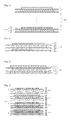
- a plurality of radical units 1 a , 1 b , 2 , 3 and 4 , including a cathode, a separator and an anode stacked in sequence are overlapped, and in each of overlapped parts, a separator sheet 5 is interposed.
- the separator sheet 5 has a length for wrapping the radical units and is disposed at the overlapped parts of the radical units while wrapping each of the radical units from the radical unit 1 a to the outermost radical unit 4 continuously.
- the terminal part of the separator sheet 5 is finished by heat welding, by attaching using an adhesive tape 6 , or the like.
- the stack/folding type electrode assembly is manufactured by arranging the radical units 1 a , 1 b , 2 , 3 and 4 on the separator sheet 5 having a long length and rolling the separator sheet 5 from one terminal part thereof one by one.
- temperature gradient may be generated between the radical units 1 a , 1 b and 2 positioned in the center portion and the radical units 3 and 4 positioned at the outer portion, thereby generating different heat emitting efficiencies.
- lifetime may decrease after use for a long time.
- a separator provided in a radical unit is mainly formed by using a polymer material, and has shrinking properties by heat.
- An overcharge test and a hot box test are performed with respect to an electrode assembly or a secondary battery including the same to evaluate stability.
- some bad electrode assemblies or secondary batteries including the same may ignite. The ignition may be generated because of the shrinkage of the separator due to heat and the short generated through the contact of a cathode and an anode.
- a separator having a larger size than an electrode may be applied in an electrode assembly.
- the edge parts of a separator are not attached to an electrode, and a series of manufacturing processes of a secondary battery is conducted without conducting specific treatment with respect to the edge parts of the separator.
- a series of manufacturing processes of a secondary battery is conducted without conducting specific treatment with respect to the edge parts of the separator.
- specific treatment with respect to the edge parts of the separator is not conducted in an electrode assembly of a stack type structure, there also is a high risk of generating short as in the electrode assembly of a stack/folding type structure 1 .
- the separator is necessary to have a quite large size when compared to the electrodes to definitely prevent the generation of short between the cathode and the anode. In this case, the volume of the secondary battery may increase.
- the production cost of a secondary battery may increase.
- An aspect of the present disclosure for solving the above-described defects provides an electrode assembly having decreased risk of inner short and improved stability even though using a separator having the same as or a somewhat smaller size of that of a common separator, and a method of manufacturing the same.
- Another aspect of the present invention is to provide an electrode assembly having decreased unit production cost and having improved stability, and a manufacturing method thereof.
- a further aspect of the present invention is to provide an electrode assembly with improved stability and a manufacturing method thereof by which the electrode assembly may be manufactured only using one kind of bi-cells.
- an electrode assembly with improved stability including a cell stack part having (a) a structure in which one kind of radical unit is repeatedly disposed, the one kind of radical unit having a same number of electrodes and separators which are alternately disposed and integrally combined, or (b) a structure in which at least two kinds of radical units are disposed in a predetermined order, the two kinds of radical units having a same number of electrodes and separators which are alternately disposed and integrally combined.
- the one kind of radical unit of (a) has a four-layered structure in which a first electrode, a first separator, a second electrode and a second separator are sequentially stacked together or a repeating structure in which the four-layered structure is repeatedly stacked, and each of the at least two kinds of radical units of (b) are stacked by ones in the predetermined order to form the four-layered structure or the repeating structure in which the four-layered structure is repeatedly stacked.
- the separator has a larger size than the electrode to expose an edge part of the separator to the outside of the electrode and the separator.
- the edge parts of the separators included in one radical unit are attached to each other to form a sealing part, or the edge parts of the separators included in the cell stack part are attached to each other to form the sealing part.
- a method of manufacturing an electrode assembly with improved stability including a step of forming one kind of a radical unit having an alternately stacked structure of a same number of electrodes and separators, or at least two kinds of radical units having an alternately stacked structure of a same number of electrodes and separators (S 10 ); a step of forming a sealing part by facing edge parts of the separators included in one radical unit and applying heat and pressure (S 20 ); and a step of forming a cell stack part by repeatedly stacking the one kind of the radical units after performing steps S 10 and S 20 , or by stacking the at least two kinds of the radical units after performing steps S 10 and S 20 in a predetermined order (S 22 ).
- the one kind of radical unit has a four-layered structure in which a first electrode, a first separator, a second electrode and a second separator are sequentially stacked together or a repeating structure in which the four-layered structure is repeatedly stacked, and each of the at least two kinds of radical units are stacked by ones in the predetermined order to form the four-layered structure or the repeating structure in which the four-layered structure is repeatedly stacked.
- a method of manufacturing an electrode assembly with improved stability including a step of forming one kind of a radical unit having an alternately stacked structure of a same number of electrodes and separators, or at least two kinds of radical units having an alternately stacked structure of a same number of electrodes and separators (S 10 ); a step of forming a cell stack part by repeatedly stacking the one kind of the radical units, or by stacking the at least two kinds of the radical units in a predetermined order (S 14 ); and a step of forming a sealing part by facing edge parts of the separators included in the cell stack part and applying heat and pressure (S 30 ).
- the one kind of radical unit has a four-layered structure in which a first electrode, a first separator, a second electrode and a second separator are sequentially stacked together or a repeating structure in which the four-layered structure is repeatedly stacked, and each of the at least two kinds of radical units are stacked by ones in the predetermined order to form the four-layered structure or the repeating structure in which the four-layered structure is repeatedly stacked.
- an electrode assembly having decreased risk of inner short and improved stability even though using a separator having the same as or a somewhat smaller size of that of a common separator, and a method of manufacturing the same, may be provided.
- an electrode assembly having decreased production cost and having improved stability and a method of manufacturing the same, may be provided.
- an electrode assembly having improved stability and a method of manufacturing the same by which the electrode assembly may be manufactured only using one kind of bi-cells, may be provided.
- FIG. 1 is a cross-sectional view conceptually illustrating a folding type structure of a common electrode assembly
- FIG. 2 is a side view illustrating a first structure of a radical unit according to the present disclosure
- FIG. 3 is a side view illustrating a second structure of a radical unit according to the present disclosure
- FIG. 4 is a side view illustrating a cell stack part formed by stacking the radical units of FIG. 2 ;
- FIG. 5 is a side view illustrating a third structure of a radical unit according to the present disclosure.
- FIG. 6 is a side view illustrating a fourth structure of a radical unit according to the present disclosure.
- FIG. 7 is a side view illustrating a cell stack part formed by stacking the radical units of FIG. 5 and the radical units of FIG. 6 ;
- FIG. 8 is a process diagram illustrating a manufacturing process of a radical unit according to the present disclosure.
- FIG. 9 is a perspective view illustrating a cell stack part formed by stacking radical units having different sizes
- FIG. 10 is a side view illustrating the cell stack part of FIG. 9 ;
- FIG. 11 is a perspective view illustrating a cell stack part formed by stacking radical units having different geometric shapes
- FIG. 12 is a side view illustrating a first structure of a cell stack part including a radical unit and a first auxiliary unit according to the present disclosure
- FIG. 13 is a side view illustrating a second structure of a cell stack part including a radical unit and a first auxiliary unit according to the present disclosure
- FIG. 14 is a side view illustrating a third structure of a cell stack part including a radical unit and a second auxiliary unit according to the present disclosure
- FIG. 15 is a side view illustrating a fourth structure of a cell stack part including a radical unit and a second auxiliary unit according to the present disclosure
- FIG. 16 is a side view illustrating a fifth structure of a cell stack part including a radical unit and a first auxiliary unit according to the present disclosure
- FIG. 17 is a side view illustrating a sixth structure of a cell stack part including a radical unit and a first auxiliary unit according to the present disclosure
- FIG. 18 is a side view illustrating a seventh structure of a cell stack part including a radical unit and a second auxiliary unit according to the present disclosure
- FIG. 19 is a side view illustrating an eighth structure of a cell stack part including a radical unit and a second auxiliary unit according to the present disclosure
- FIG. 20 is a side view illustrating a ninth structure of a cell stack part including a radical unit and a first auxiliary unit according to the present disclosure
- FIG. 21 is a side view illustrating a tenth structure of a cell stack part including a radical unit, a first auxiliary unit, and a second auxiliary unit according to the present disclosure
- FIG. 22 is a side view illustrating an eleventh structure of a cell stack part including a radical unit and a second auxiliary unit according to the present disclosure
- FIG. 23 is a cross-sectional view illustrating a stacked state of a separator on the first structure of the radical unit in FIG. 2 ;
- FIG. 24 is a cross-sectional view illustrating a stacked state of a separator on an uppermost electrode after stacking the first structure of the radical unit in FIG. 2 twice;
- FIG. 25 is a cross-sectional view illustrating a cell stack part including a sealing part by attaching edge parts of the separators in FIG. 23 ;
- FIG. 26 is a cross-sectional view illustrating a cell stack part including a sealing part by attaching edge parts of the separators in FIG. 23 .
- An electrode assembly includes a cell stack part having a structure obtained by stacking radical units repeatedly or in a predetermined order, or having a structure obtained by further stacking an auxiliary unit on the cell stack part.
- a sealing part may be formed by attaching the edge parts of separators having a larger size than electrodes by the radical unit, or a sealing part may be formed by attaching the edge parts of all separators present in the cell stack part having a structure obtained by stacking radical units repeatedly or in a predetermined order at the same time.
- the structure of the radical unit and the auxiliary unit possibly stacked on the radical unit, and the structure of the cell stack part having a plurality of stacked radical units may be attained diversely. Therefore, these structures will be explained first, and the formation of the sealing part in the radical unit or the formation of the sealing part in the cell stack part at the same time will be subsequently explained.
- the cell stack part has a structure obtained by repeatedly disposing one kind of radical units or a structure obtained by disposing at least two kinds of radical units in a predetermined order, for example, alternately. This will be described below in more detail.
- a radical unit is formed by alternately disposing electrodes and separators.
- the same number of electrodes and separators are disposed.
- a radical unit 110 a may be formed by stacking two electrodes 111 and 113 and two separators 112 and 114 .
- a cathode and an anode may naturally face each other through the separator.
- an electrode 111 is positioned at one end part of the radical unit (see electrode 111 in FIGS. 2 and 2 ) and a separator 114 is positioned at the other end part of the radical unit (see separator 114 in FIGS. 2 and 2 ).
- the electrode assembly according to the present disclosure is basically characterized in that the cell stack part or electrode assembly is formed by only stacking the radical units. That is, the present disclosure has a basic characteristic in that the cell stack part is formed by repeatedly stacking one kind of radical unit or by stacking at least two kinds of radical units in a predetermined order. To realize the above-described characteristic, the radical unit may have the following structure.
- the radical unit may be formed by stacking a first electrode, a first separator, a second electrode, and a second separator in sequence.
- a first electrode 111 , a first separator 112 , a second electrode 113 , and a second separator 114 may be stacked in sequence from an upper side to a lower side, as illustrated in FIG. 2 , or from the lower side to the upper side, as illustrated in FIG. 3 , to form radical units 110 a and 110 b .
- the radical unit having the above-described structure may be referred to as a first radical unit.
- the first electrode 111 and the second electrode 113 may be opposite types of electrodes.
- the second electrode 113 may be an anode.
- a cell stack part 100 a may be formed by only repeatedly stacking the one kind of radical units 110 a , as illustrated in FIG. 4 .
- the radical unit may have an eight-layered structure or twelve-layered structure in addition to a four-layered structure. That is, the radical unit may have a repeating structure in which the four-layered structure is repeatedly disposed.
- the radical unit may be formed by stacking the first electrode 111 , the first separator 112 , the second electrode 113 , the second separator 114 , the first electrode 111 , the first separator 112 , the second electrode 113 , and the second separator 114 in sequence.
- the radical unit may be formed by stacking the first electrode 111 , the first separator 112 , the second electrode 113 , the second separator 114 , the first electrode 111 , and the first separator 112 in sequence, or by stacking the second electrode 113 , the second separator 114 , the first electrode 111 , the first separator 112 , the second electrode 113 , and the second separator 114 in sequence.
- the radical unit having the former structure may be referred to as a second radical unit and the radical unit having the latter structure may be referred to as a third radical unit.
- the second radical unit 100 c may be formed by stacking the first electrode 111 , the first separator 112 , the second electrode 113 , the second separator 114 , the first electrode 111 , and the first separator 112 in sequence from the upper side to the lower side, as illustrated in FIG. 5 .
- the third radical structure 110 d may be formed by stacking the second electrode 113 , the second separator 114 , the first electrode 111 , the first separator 112 , the second electrode 113 , and the second separator 114 in sequence from the upper side to the lower side, as illustrated in FIG. 6 . As noted above, the stacking may be conducted in sequence from the lower side to the upper side.
- the cell stack part 100 b may be formed by stacking only the second and third radical units, as illustrated in FIG. 7 .
- the cell stack part may be formed by stacking the radical units in a predetermined order, for example, the first radical unit, the second radical unit, the third radical unit, the first radical unit again, the second radical unit, and the third radical unit.
- the one kind of radical unit in the present disclosure has a four-layered structure in which a first electrode, a first separator, a second electrode and a second separator are sequentially stacked, or has a repeating structure in which the four-layered structure is repeatedly stacked.
- at least two kinds of radical units in the present disclosure are stacked only by ones in a predetermined order to form the four-layered structure or the repeating structure in which the four-layered structure is repeatedly disposed.
- the first radical unit forms a four-layered structure by itself
- the second radical unit and the third radical unit form a twelve-layered structure by stacking one of each, that is, two radical units in total.
- the cell stack part or electrode assembly may be formed only by stacking, that is, by repeatedly stacking one kind of radical unit or by stacking at least two kinds of radical units in a predetermined order.
- the cell stack part of the present disclosure may be formed by stacking the radical units one by one. That is, the cell stack part may be manufactured by forming the radical units and then stacking the radical units repeatedly or in a predetermined order. As described above, the cell stack part of the present disclosure may be formed by only stacking the radical units. Therefore, the radical units of the present disclosure may be very accurately aligned. When the radical unit is accurately aligned, the electrode and the separator may also be accurately aligned in the cell stack part. In addition, the cell stack part or electrode assembly may be improved in productivity. This is done because the manufacturing process is very simple.
- a manufacturing process of the first radical unit will be exemplarily described with reference to FIG. 8 .
- a first electrode material 121 , a first separator material 122 , a second electrode material 123 and a second separator material 124 are prepared.
- the first separator material 122 and the second separator material 124 may be the same.
- the first electrode material 121 is cut into a certain size through a cutter C1
- the second electrode material 123 is cut into a certain size through a cutter C2.
- the first electrode material 121 is stacked on the first separator material 122
- the second electrode material 123 is stacked on the second separator material 124 .
- the electrode materials and the separator materials are attached to each other through laminators L1 and L2.
- a radical unit in which the electrodes and the separators are integrally combined may be formed.
- the combining method may be diverse.
- the laminators L1 and L2 may apply pressure to the materials or apply pressure and heat to the materials to attach the materials to each other. Because of the attachment, the stacking of the radical units may be more easily performed while manufacturing the cell stack part. Also, the alignment of the radical units may be also easily accomplished because of the attachment.
- the first separator material 122 and the second separator material 124 are cut into a certain size through a cutter C3 to manufacture the radical unit 110 a.
- the electrode may be attached to the adjacent separator in the radical unit.
- the separator may be attached to the adjacent electrode.
- the electrode may be stably fixed to the separator.
- the electrode has a size less than that of the separator.
- an adhesive may be applied to the separator.
- the adhesive it is necessary to apply the adhesive over an adhesion surface of the separator in a mesh or dot shape. This is because if the adhesive is closely applied to the entire adhesion surface, reactive ions such as lithium ions may not pass through the separator. Thus, when the adhesive is used, it is difficult to allow the overall surface of the electrode to closely attach to the adjacent separator.
- the separator may include a porous separator base material such as a polyolefin-based separator base material and a porous coating layer that is generally applied to one side or both sides of the separator base material.
- the coating layer may be formed of a mixture of inorganic particles and a binder polymer that binds and fixes the inorganic particles to each other.
- the inorganic particles may improve thermal stability of the separator. That is, the inorganic particles may prevent the separator from being contracted at a high temperature.
- the binder polymer may fix the inorganic particles to improve mechanical stability of the separator.
- the binder polymer may attach the electrode to the separator. Since the binder polymer is generally distributed in the coating layer, the electrode may closely adhere to the entire adhesion surface of the separator, unlike the foregoing adhesive. Thus, when the separator is used as described above, the electrode may be more stably fixed to the separator. To enhance the adhesion, the above-described laminators may be used.
- the inorganic particles may have a densely packed structure to form interstitial volumes between the inorganic particles over the overall coating layer.
- a pore structure may be formed in the coating layer by the interstitial volumes that are defined by the inorganic particles. Due to the pore structure, even though the coating layer is formed on the separator, the lithium ions may smoothly pass through the separator.
- the interstitial volume defined by the inorganic particles may be blocked by the binder polymer according to a position thereof.
- the densely packed structure may be explained as a structure in which gravels are contained in a glass bottle.
- the inorganic particles form the densely packed structure
- the interstitial volumes between the inorganic particles are not locally formed in the coating layer, but generally formed in the coating layer.
- the pore formed by the interstitial volume also increases in size. Due the above-described densely packed structure, the lithium ions may smoothly pass through the separator over the entire surface of the separator.
- the radical units may also adhere to each other in the cell stack part. For example, if the adhesive or the above-described coating layer is applied to a bottom surface of the second separator 114 in FIG. 2 , the other radical unit may adhere to the bottom surface of the second separator 114 .
- the adhesive strength between the electrode and the separator in the radical unit may be greater than that between the radical units in the cell stack part. It is understood, that the adhesive strength between the radical units may not be provided. In this case, when the electrode assembly or the cell stack part is disassembled, the electrode assembly may be separated into the radical units due to a difference in the adhesive strength.
- the adhesive strength may be expressed as delamination strength.
- the adhesive strength between the electrode and the separator may be expressed as a force required for separating the electrode from the separator.
- the radical unit may not be bonded to the adjacent radical unit in the cell stack part, or may be bonded to the adjacent radical unit in the cell stack part by means of a bonding strength differing from a bonding strength between the electrode and the separator.
- the separator when the separator includes the above-described coating layer, it is not preferable to perform ultrasonic welding on the separator.
- the separator has a size greater than that of the electrode.
- the separator may adhere to the horn due to the coating layer having the adhesive strength. As a result, the welding apparatus may be broken down.
- radical units having the same size have been explained.
- the radical units may have different sizes.
- cell stack parts having various shapes may be manufactured.
- the size of the radical unit is explained with reference to the size of the separator, because, typically, the separator is larger than the electrode.
- a plurality of radical units is prepared and may be classified into at least two groups having different sizes (see reference numerals 1101 a , 1102 a and 1103 a in FIG. 10 ).
- a cell stack part 100 c having a structure of a plurality of steps may be formed.
- FIGS. 9 and 10 illustrate an embodiment in which the cell stack part includes three steps obtained by stacking the radical units 1101 a , 1102 a and 1103 a classified into three groups, in which the radical units having the same size are stacked together, is illustrated.
- the radical units included in one group may form two or more steps.
- the radical unit has a structure of the first radical unit, that is, the above-described four-layered structure or the repeating structure in which the four-layered structure is repeatedly stacked.
- the radical units are considered to be included in one kind of radical unit even though the radical units have the same stacked structures but have different sizes.
- the same number of cathodes and the anodes are stacked in one step. Also, it is preferable that opposite electrodes face each other through a separator between one step and another step.
- the second and third radical units two kinds of the radical units are necessary for forming one step.
- the radical unit has the four-layered structure or the repeating structure in which the four-layered structure is repeatedly stacked, number of kinds of radical units may decrease even though a plurality of the steps is formed.
- the one step may have at least a twelve-layered structure.
- the first radical unit only one kind of radical unit is necessary to be stacked to form one step.
- one step may have at least a four-layered structure.
- the radical units may have not only different sizes but also different geometric shapes.
- the radical units may have different sizes and different edge shapes, and may or may not have a through hole as illustrated in FIG. 11 .
- a plurality of radical units classified into three groups may form three steps by stacking the radical units having the same geometric shapes.
- the radical units may be classified into at least two groups (each of the groups has different geometric shape).
- the radical unit may preferably have the four-layered structure or the repeating structure in which the four-layered structures are repeatedly stacked, that is, the structure of the first radical unit. (Herein, the radical units are considered to be included in one kind of radical unit even though the radical units have the same stacked structure but have different geometric shapes.)
- the cell stack part may further include at least one among a first auxiliary unit and a second auxiliary unit.
- the first auxiliary unit will be described below.
- an electrode is positioned at one end of the radical unit, and a separator is positioned at the other end of the radical unit.
- the electrode may be positioned at the uppermost portion or at the lowermost portion of the cell stack part (see reference numeral 116 in FIG. 12 , and this electrode may be referred to as a terminal electrode 116 ).
- the first auxiliary unit is additionally stacked on the terminal electrode.
- the first auxiliary unit 130 a may be formed by stacking outward from the terminal electrode 116 , a separator 114 , an anode 113 , a separator 112 , and a cathode 111 in sequence, as illustrated in FIG. 12 .
- the terminal electrode 116 is an anode
- the first auxiliary unit 130 b may be formed by stacking outward from the terminal electrode 116 , the separator 114 , and the cathode 113 in sequence, as illustrated in FIG. 13 .
- a cathode may be positioned at the outermost portion of a terminal electrode through the first auxiliary units 130 a and 130 b , as illustrated in FIGS. 12 and 13 .
- an active material layer is preferably coated on only one side facing the radical unit (one side facing downward in FIG. 12 ) among both sides of the current collector.
- the active material layer is not positioned at the outermost portion of the cell stack part. Thus, waste of the active material layer may be prevented.
- the cathode emits, for example, lithium ions, when the cathode is positioned at the outermost portion, the capacity of a battery may be improved.
- the second auxiliary unit performs the same function as the first auxiliary unit, which will be described below in more detail.
- an electrode is positioned at one end of the radical unit, and a separator is positioned at the other end of the radical unit.
- the separator may be positioned at the uppermost portion or at the lowermost portion of the cell stack part (see reference numeral 117 in FIG. 14 , and this separator may be referred to as a terminal separator 117 ).
- the second auxiliary unit is additionally stacked on the terminal separator.
- the second auxiliary unit 140 a when the electrode 113 contacting the terminal separator 117 is a cathode in the radical unit, the second auxiliary unit 140 a may be formed by stacking from the terminal separator 117 , an anode 111 , a separator 112 , and a cathode 113 in sequence, as illustrated in FIG. 14 .
- the second auxiliary unit 140 b when the electrode 113 contacting the terminal separator 117 is an anode in the radical unit, the second auxiliary unit 140 b may be formed as the cathode 111 , as illustrated in FIG. 15 .
- a cathode may be positioned at the outermost portion of a terminal separator through the second auxiliary units 140 a and 140 b , as illustrated in FIGS. 14 and 15 .
- an active material layer is preferably coated on only one side facing the radical unit (one side facing upward in FIG. 14 ) among both sides of the current collector, as similar to the cathode of the first auxiliary unit.
- the first auxiliary unit and the second auxiliary unit may have different structures from those described above.
- the first auxiliary unit will be described below.
- the terminal electrode 116 is a cathode as illustrated in FIG. 16
- the first auxiliary unit 130 c may be formed by stacking from the terminal electrode 116 , a separator 114 , and an anode 113 in sequence.
- the terminal electrode 116 is an anode as illustrated in FIG. 17
- the first auxiliary unit 130 d may be formed by stacking from the terminal electrode 116 , a separator 114 , a cathode 113 , a separator 112 , and an anode 111 in sequence.
- an anode may be positioned at the outermost portion of the terminal electrode through the first auxiliary units 130 c and 130 d , as illustrated in FIGS. 16 and 17 .
- the second auxiliary unit 140 c when the electrode 113 contacting the terminal separator 117 is a cathode in the radical unit, the second auxiliary unit 140 c may be formed as an anode 111 .
- the second auxiliary unit 140 d when the electrode 113 contacting the terminal separator 117 is an anode in the radical unit, the second auxiliary unit 140 d may be formed by stacking from the terminal separator 117 , the cathode 111 , the separator 112 , and the anode 113 in sequence. In the cell stack parts 100 j and 100 k , an anode may be positioned at the outermost portion of the terminal separator through the second auxiliary units 140 c and 140 d , as illustrated in FIGS. 18 and 19 .
- an anode may make a reaction with an aluminum layer of a battery case (for example, a pouch-type case) due to potential difference.
- the anode is preferably insulated from the battery case by means of a separator.
- the first and second auxiliary units in FIGS. 16 to 19 may further include a separator at the outer portion of the anode.
- the first auxiliary unit 130 e in FIG. 20 may further include a separator 112 at the outermost portion thereof when compared to the first auxiliary unit 130 c in FIG. 16 .
- the auxiliary unit includes the separator, the alignment of the auxiliary units in the radical unit may be easily performed.
- a cell stack part 100 m may be formed as illustrated in FIG. 21 .
- a radical unit 110 b may be formed by stacking from the lower portion to the upper portion, a first electrode 111 , a first separator 112 , a second electrode 113 , and a second separator 114 in sequence.
- the first electrode 111 may be a cathode
- the second electrode 113 may be an anode.
- a first auxiliary unit 130 f may be formed by stacking from the terminal electrode 116 , the separator 114 , the anode 113 , the separator 112 and the cathode 111 in sequence.
- the cathode 111 of the first auxiliary unit 130 f only one side of a current collector facing the radical unit 110 b among both sides of the current collector may be coated with an active material layer.
- a second auxiliary unit 140 e may be formed by stacking from the terminal separator 117 , the cathode 111 (the first cathode), the separator 112 , the anode 113 , the separator 114 , and the cathode 118 (the second cathode) in sequence.
- the cathode 118 (the second cathode) of the second auxiliary unit 140 e positioned at the outermost portion only one side of a current collector facing the radical unit 110 b among both sides of the current collector may be coated with an active material layer.
- a cell stack part 100 n may be formed as illustrated in FIG. 22 .
- a radical unit 110 e may be formed by stacking from the upper portion to the lower portion, a first electrode 111 , a first separator 112 , a second electrode 113 , and a second separator 114 in sequence.
- the first electrode 111 may be an anode
- the second electrode 113 may be a cathode.
- a second auxiliary unit 140 f may be formed by stacking from the terminal separator 117 , the anode 111 , the separator 112 , the cathode 113 , the separator 114 , and the anode 119 in sequence.
- the structure of the radical unit, the structure of the auxiliary unit that may be stacked on the radical unit, and the structure of the cell stack part having the plurality of stacked radical units have been explained.
- the manufacturing of the cell stack part (electrode assembly) by forming a sealing part A at the radical unit itself or by forming a sealing part A at the cell stack part at the same time will be explained referring to the first radical unit illustrated in FIG. 2 for convenience.
- the electrode assembly may correspond to the cell stack part itself or the cell stack part wrapped in a tape for fixing.
- the electrode assembly according to the present disclosure is provided with a cell stack part having a repeatedly stacked structure of one kind of the radical units including the same number of alternately stacked electrodes and separators, or having a stacked structure of two or more kinds of the radical units including the same number of alternately stacked electrodes and separators in a predetermined order.
- FIG. 23 is a cross-sectional view illustrating a stacked state of a separator on a first structure of the radical unit in FIG. 2
- FIG. 24 is a cross-sectional view illustrating a stacked state of a separator on an uppermost electrode after stacking a first structure of the radical unit in FIG. 2 twice.
- a separator S is additionally stacked on the uppermost electrode of the cell stack part, and the top surface of the uppermost electrode and the bottom surface of the lowermost electrode are covered with separators.
- the separators S may be additionally stacked on the lowermost electrodes of the cell stack parts.
- FIGS. 23 and 24 The edge portions of adjacent separators in FIGS. 23 and 24 are placed to meet each other, and heat and pressure are applied to attach the edge parts of the separators, thereby forming sealing parts A illustrated in FIGS. 25 and 26 .
- the sealing part A may be formed by attaching the edge parts of the separators included in one radical unit during manufacturing the electrode assembly.
- the sealing part A may be formed by stacking the radical units (of course, the auxiliary unit may be stacked together) to form the cell stack part and then, attaching the edge parts of all of the separators included in the cell stack parts together.
- a step of manufacturing one kind of radical units having an alternately stacked structure of the same number of electrodes and separators or two, or more kinds of radical units having an alternately stacked structure of the same number of electrodes and separators is conducted (S 10 ).
- a step of manufacturing a cell stack part is conducted by repeatedly stacking one kind of the radical units after performing Step S 10 and Step S 20 , or by stacking two or more kinds of the radical units after performing Step S 10 and Step S 20 in order (S 22 ).
- a cell stack part (an electrode assembly) having a stacked structure of the radical units may be manufactured.
- Step S 10 is performed first as in the above embodiment, and a step of manufacturing a cell stack part by repeatedly stacking one kind of the radical units or by stacking two or more kinds of the radical units in order is performed (S 14 ). Then, the edge parts of separators included in the cell stack part are placed to meet each other, and heat and pressure are applied to form a sealing part A (S 30 ).
- a cell stack part is manufactured first by stacking the radical units without forming the sealing part A from the edge parts of the separators provided in the radical units, and then, the sealing part A is formed by using the edge parts of all the separators included in the cell stack part at the same time.
- a cell stack part including the separators at both of the uppermost and the lowermost parts may be manufactured.
- the heat and the pressure applied to the edge parts of adjacent separators to form the sealing part A in Step S 20 and Step S 30 are preferably and respectively 50° C. to 100° C. and 10 gf/cm 2 to 20 gf/cm 2 .
- the formation of a satisfactory sealing part A may be performed by only applying the heat and the pressure to the edge parts of the adjacent separators for 3 to 5 seconds in Step S 20 or Step S 30 .
- the time necessary for the manufacture of electrode assembly may not significantly increase due to the forming steps (S 20 and S 30 ) of the sealing part A.
- a pressure of about 100 Kgf/cm 2 is necessary to attach the cathode and the anode, on the contrary, the above described pressure of 10 gf/cm 2 to 20 gf/cm 2 applied to the edge parts of the separators for the formation of the sealing part A is sufficient.
- the sealing part A may be formed by applying significantly less pressure than that applied to attach the cathode and the anode to the separator.
- the shrinkage ratio of the separator was found to decrease when the edge parts of the separator were overlapped when compared to that of the separator when the edge parts of the separators were not overlapped and separately stacked between the cathodes and the anodes.
- the decreasing effect of the shrinkage ratio due to the overlapping and the decreasing effect of the shrinkage ratio due to the attachment of the separators are combined, and the shrinkage ratio of the separators may be markedly decreased.
- an electrode assembly having improved stability when considering the common electrode assembly may be manufactured even though a separator having the same size or somewhat smaller size than the common technology is used.
- the volume of a secondary battery may decrease.
Landscapes
- Engineering & Computer Science (AREA)
- Manufacturing & Machinery (AREA)
- Chemical & Material Sciences (AREA)
- Chemical Kinetics & Catalysis (AREA)
- Electrochemistry (AREA)
- General Chemical & Material Sciences (AREA)
- Secondary Cells (AREA)
- Cell Separators (AREA)
- Battery Electrode And Active Subsutance (AREA)
Priority Applications (2)
| Application Number | Priority Date | Filing Date | Title |
|---|---|---|---|
| US15/972,983 US10811722B2 (en) | 2013-02-15 | 2018-05-07 | Electrode assembly with improved stability and method of manufacturing the same |
| US16/999,811 US11171353B2 (en) | 2013-02-15 | 2020-08-21 | Electrode assembly with improved stability and method of manufacturing the same |
Applications Claiming Priority (5)
| Application Number | Priority Date | Filing Date | Title |
|---|---|---|---|
| KR10-2013-0016512 | 2013-02-15 | ||
| KR20130016512 | 2013-02-15 | ||
| KR10-2014-0017701 | 2014-02-17 | ||
| KR1020140017701A KR101595644B1 (ko) | 2013-02-15 | 2014-02-17 | 안전성이 향상된 전극 조립체 및 그 제조방법 |
| PCT/KR2014/001268 WO2014126432A1 (ko) | 2013-02-15 | 2014-02-17 | 안전성이 향상된 전극 조립체 및 그 제조방법 |
Related Parent Applications (1)
| Application Number | Title | Priority Date | Filing Date |
|---|---|---|---|
| PCT/KR2014/001268 Continuation WO2014126432A1 (ko) | 2013-02-15 | 2014-02-17 | 안전성이 향상된 전극 조립체 및 그 제조방법 |
Related Child Applications (1)
| Application Number | Title | Priority Date | Filing Date |
|---|---|---|---|
| US15/972,983 Continuation US10811722B2 (en) | 2013-02-15 | 2018-05-07 | Electrode assembly with improved stability and method of manufacturing the same |
Publications (2)
| Publication Number | Publication Date |
|---|---|
| US20140363727A1 US20140363727A1 (en) | 2014-12-11 |
| US10084200B2 true US10084200B2 (en) | 2018-09-25 |
Family
ID=51747585
Family Applications (3)
| Application Number | Title | Priority Date | Filing Date |
|---|---|---|---|
| US14/468,786 Active 2035-06-02 US10084200B2 (en) | 2013-02-15 | 2014-08-26 | Electrode assembly with improved stability and method of manufacturing the same |
| US15/972,983 Active 2034-06-17 US10811722B2 (en) | 2013-02-15 | 2018-05-07 | Electrode assembly with improved stability and method of manufacturing the same |
| US16/999,811 Active US11171353B2 (en) | 2013-02-15 | 2020-08-21 | Electrode assembly with improved stability and method of manufacturing the same |
Family Applications After (2)
| Application Number | Title | Priority Date | Filing Date |
|---|---|---|---|
| US15/972,983 Active 2034-06-17 US10811722B2 (en) | 2013-02-15 | 2018-05-07 | Electrode assembly with improved stability and method of manufacturing the same |
| US16/999,811 Active US11171353B2 (en) | 2013-02-15 | 2020-08-21 | Electrode assembly with improved stability and method of manufacturing the same |
Country Status (7)
| Country | Link |
|---|---|
| US (3) | US10084200B2 (ja) |
| EP (1) | EP2958179B1 (ja) |
| JP (1) | JP6232069B2 (ja) |
| KR (1) | KR101595644B1 (ja) |
| CN (1) | CN104854752B (ja) |
| TW (1) | TWI520405B (ja) |
| WO (1) | WO2014126432A1 (ja) |
Cited By (1)
| Publication number | Priority date | Publication date | Assignee | Title |
|---|---|---|---|---|
| US11518156B2 (en) * | 2019-01-14 | 2022-12-06 | Toyota Jidosha Kabushiki Kaisha | Laminated body pressing apparatus, pressed strip-shaped laminated body manufacturing method, laminated electrode body manufacturing method, and battery manufacturing method |
Families Citing this family (25)
| Publication number | Priority date | Publication date | Assignee | Title |
|---|---|---|---|---|
| KR101561735B1 (ko) * | 2013-09-25 | 2015-10-19 | 주식회사 엘지화학 | 전극조립체 제조방법 |
| KR101619604B1 (ko) | 2013-09-26 | 2016-05-10 | 주식회사 엘지화학 | 전극조립체 및 이차전지의 제조방법 |
| KR101609424B1 (ko) * | 2013-09-26 | 2016-04-05 | 주식회사 엘지화학 | 전극조립체의 제조방법 |
| KR101826142B1 (ko) * | 2015-08-27 | 2018-02-07 | 삼성에스디아이 주식회사 | 전극 조립체 및 그 제조 방법과 이차 전지 |
| KR102050023B1 (ko) * | 2015-09-07 | 2019-11-28 | 주식회사 엘지화학 | 전극조립체의 제조방법, 그 전극조립체 및 이를 포함하는 이차전지 |
| KR102261176B1 (ko) * | 2015-11-26 | 2021-06-07 | 주식회사 엘지에너지솔루션 | 이차전지의 제조방법 |
| DE102016218495A1 (de) * | 2016-09-27 | 2018-03-29 | Robert Bosch Gmbh | Verfahren zur Herstellung eines Elektrodenstapels für eine Batteriezelle und Batteriezelle |
| DE102016218496A1 (de) | 2016-09-27 | 2018-03-29 | Robert Bosch Gmbh | Verfahren zur Herstellung einer Elektrodeneinheit für eine Batteriezelle und Elektrodeneinheit |
| JP6787241B2 (ja) | 2017-04-28 | 2020-11-18 | トヨタ自動車株式会社 | 電極積層体及び電池の製造方法 |
| CN107482163A (zh) * | 2017-07-11 | 2017-12-15 | 多氟多(焦作)新能源科技有限公司 | 一种电极组件单元、电极组件的制造方法及电池单体 |
| EP3454404B1 (en) * | 2017-09-12 | 2021-06-23 | Robert Bosch GmbH | Method for joining an electrode stack |
| DE102017216138A1 (de) | 2017-09-13 | 2019-03-14 | Robert Bosch Gmbh | Verfahren zur Herstellung eines Elektrodenstapels für eine Batteriezelle und Batteriezelle |
| KR101837724B1 (ko) * | 2017-11-15 | 2018-03-12 | 이소라 | 적층식 이차전지 제조방법 |
| EP3486989A1 (en) * | 2017-11-15 | 2019-05-22 | Lee, Sora | Manufacturing method for laminated secondary battery |
| KR102254264B1 (ko) * | 2018-02-01 | 2021-05-21 | 주식회사 엘지에너지솔루션 | 전극조립체 및 이의 제조 방법 |
| JP7037992B2 (ja) * | 2018-04-09 | 2022-03-17 | 日産自動車株式会社 | 電池の製造方法 |
| DE102018215070A1 (de) | 2018-09-05 | 2020-03-05 | Gs Yuasa International Ltd. | Verfahren zur Bildung eines Elektrodenstapels |
| KR102314631B1 (ko) * | 2018-09-19 | 2021-10-20 | 주식회사 엘지에너지솔루션 | 전극조립체 |
| CN109888360B (zh) * | 2019-01-26 | 2021-08-27 | 温在东 | 叠片电芯结构及适于其分体式叠片、贴胶的生产方法 |
| KR20200113822A (ko) * | 2019-03-26 | 2020-10-07 | 주식회사 엘지화학 | 전극조립체 및 그 전극조립체 제조용 라미네이션 장치 및 그 전극조립체의 제조 방법 |
| CN110277590B (zh) * | 2019-06-28 | 2022-04-12 | 蜂巢能源科技有限公司 | 用于电芯制造的叠片方法和电芯极组制造装备 |
| CN110265731A (zh) * | 2019-07-15 | 2019-09-20 | 东莞市超鸿自动化设备有限公司 | 摇摆式切叠一体机 |
| KR20210064831A (ko) * | 2019-11-26 | 2021-06-03 | 주식회사 엘지화학 | 전극조립체 및 그 제조방법 |
| FR3109673B1 (fr) * | 2020-04-22 | 2022-08-12 | Pellenc Energy | Composant à reliefs de rétention de matière active pour accumulateur d’énergie électrique, accumulateur d’énergie électrique utilisant le composant et procédé de fabrication |
| WO2022224596A1 (ja) * | 2021-04-23 | 2022-10-27 | 株式会社村田製作所 | 非水電解質二次電池 |
Citations (27)
| Publication number | Priority date | Publication date | Assignee | Title |
|---|---|---|---|---|
| JP2001028275A (ja) | 1999-06-25 | 2001-01-30 | Mitsubishi Chemicals Corp | 立体自由形状バッテリー装置 |
| JP2001167743A (ja) | 1999-12-09 | 2001-06-22 | Sharp Corp | 二次電池及びそれを用いた電子機器 |
| KR20010082059A (ko) | 2000-02-08 | 2001-08-29 | 성재갑 | 중첩 전기화학 셀 및 그의 제조 방법 |
| KR20010082058A (ko) | 2000-02-08 | 2001-08-29 | 성재갑 | 중첩 전기 화학 셀 |
| KR20010082060A (ko) | 2000-02-08 | 2001-08-29 | 성재갑 | 다중 중첩 전기화학 셀 및 그의 제조방법 |
| JP2002208442A (ja) | 2001-01-11 | 2002-07-26 | Tdk Corp | 電気化学デバイス |
| TW499767B (en) | 2000-02-23 | 2002-08-21 | Sony Corp | Electrode and battery, and methods of producing the same |
| US20060046149A1 (en) | 2004-09-02 | 2006-03-02 | Yong Hyun H | Organic/inorganic composite porous film and electrochemical device prepared thereby |
| US20060115718A1 (en) | 2004-11-30 | 2006-06-01 | Delphi Technologies, Inc. | Lithium ion polymer multi-cell and method of making |
| US20070154790A1 (en) * | 2006-01-04 | 2007-07-05 | Lg Chem, Ltd. | Battery assembly employed with separator of sealed top portion and secondary battery comprising the same |
| US20070254199A1 (en) | 2006-05-01 | 2007-11-01 | Hsi-Ming Shu | Assembly method for assembling plate-type membrane electrode assembly layer and the structure thereof |
| WO2008002024A1 (en) | 2006-06-26 | 2008-01-03 | Lg Chem, Ltd. | Electrode plate for battery cell and process of preparing the same |
| KR20080005629A (ko) | 2006-07-10 | 2008-01-15 | 주식회사 엘지화학 | 향상된 안전성의 스택/폴딩형 전극조립체 및 이를 포함하는전기화학 셀 |
| US20080044689A1 (en) | 2006-08-18 | 2008-02-21 | Hsi-Ming Shu | Pallet-type membrane electrode assembly layer structure |
| JP2009540523A (ja) | 2006-06-13 | 2009-11-19 | エルジー・ケム・リミテッド | 2種以上の動作電圧を提供する積層型二次電池 |
| US20100003590A1 (en) * | 2007-07-25 | 2010-01-07 | Lg Chem, Ltd. | Electrochemical device and its manufacturing method |
| KR20100046091A (ko) | 2008-10-17 | 2010-05-06 | 주식회사 케이티 | 데이터 서비스 제공 제어 방법 및 장치 |
| US20110052964A1 (en) | 2007-12-14 | 2011-03-03 | Lg Chem, Ltd. | Stack/folding-typed electrode assembly and method for preparation of the same |
| KR20110037781A (ko) | 2009-10-07 | 2011-04-13 | 에스케이이노베이션 주식회사 | 전지용 전극조립체 및 그 제조방법 |
| US20110135996A1 (en) | 2009-12-07 | 2011-06-09 | Changbum Ahn | Electrode assembly block and method of manufacturing the same, and secondary battery and method of manufacturing the same |
| EP2337107A1 (en) | 2009-12-17 | 2011-06-22 | Samsung SDI Co., Ltd. | Rechargeable battery |
| US20110195298A1 (en) | 2008-09-08 | 2011-08-11 | Nec Energy Devices, Ltd. | Stacked secondary battery |
| US20110244304A1 (en) * | 2010-03-30 | 2011-10-06 | Sanyo Electric Co., Ltd. | Stack type battery |
| KR20110112241A (ko) | 2010-04-06 | 2011-10-12 | 주식회사 엘지화학 | 스택 타입 셀, 개선된 바이-셀, 이들을 이용한 이차 전지용 전극 조립체 및 그 제조 방법 |
| US20120135299A1 (en) * | 2010-10-19 | 2012-05-31 | Yo-Han Kwon | Cable-type secondary battery |
| US20120189894A1 (en) * | 2011-01-26 | 2012-07-26 | Samsung Sdi Co., Ltd. | Electrode assembly and secondary battery including the same |
| US20130236766A1 (en) | 2010-11-01 | 2013-09-12 | Amogreentech Co., Ltd. | Heat-resistant separator, electrode assembly and secondary battery using the same, and method for manufacturing secondary battery |
Family Cites Families (5)
| Publication number | Priority date | Publication date | Assignee | Title |
|---|---|---|---|---|
| JP2000516708A (ja) * | 1996-08-08 | 2000-12-12 | ウィリアム・マーシュ・ライス・ユニバーシティ | ナノチューブ組立体から作製された巨視的操作可能なナノ規模の装置 |
| KR100440934B1 (ko) | 2002-02-06 | 2004-07-21 | 삼성에스디아이 주식회사 | 이차전지 |
| CN102341948B (zh) * | 2009-03-05 | 2014-04-16 | 日产自动车株式会社 | 双极型二次电池及其生产方法 |
| KR101024927B1 (ko) | 2009-07-30 | 2011-03-31 | 노바테크인더스트리 주식회사 | 에칭 공정에서의 세정 방법 |
| US9318733B2 (en) * | 2012-12-27 | 2016-04-19 | Lg Chem, Ltd. | Electrode assembly of stair-like structure |
-
2014
- 2014-02-17 CN CN201480003373.2A patent/CN104854752B/zh active Active
- 2014-02-17 EP EP14751378.2A patent/EP2958179B1/en active Active
- 2014-02-17 WO PCT/KR2014/001268 patent/WO2014126432A1/ko active Application Filing
- 2014-02-17 KR KR1020140017701A patent/KR101595644B1/ko active IP Right Grant
- 2014-02-17 JP JP2015529706A patent/JP6232069B2/ja active Active
- 2014-02-17 TW TW103105168A patent/TWI520405B/zh active
- 2014-08-26 US US14/468,786 patent/US10084200B2/en active Active
-
2018
- 2018-05-07 US US15/972,983 patent/US10811722B2/en active Active
-
2020
- 2020-08-21 US US16/999,811 patent/US11171353B2/en active Active
Patent Citations (48)
| Publication number | Priority date | Publication date | Assignee | Title |
|---|---|---|---|---|
| JP2001028275A (ja) | 1999-06-25 | 2001-01-30 | Mitsubishi Chemicals Corp | 立体自由形状バッテリー装置 |
| JP2001167743A (ja) | 1999-12-09 | 2001-06-22 | Sharp Corp | 二次電池及びそれを用いた電子機器 |
| US20010005561A1 (en) | 1999-12-09 | 2001-06-28 | Kazuo Yamada | Secondary battery and electronic instrument using it |
| US20020160257A1 (en) * | 2000-02-08 | 2002-10-31 | Hyang-Mok Lee | Stacked electrochemical cell and method for preparing the same |
| US20030013012A1 (en) | 2000-02-08 | 2003-01-16 | Soon-Ho Ahn | Stacked electrochemical cell |
| KR20010082060A (ko) | 2000-02-08 | 2001-08-29 | 성재갑 | 다중 중첩 전기화학 셀 및 그의 제조방법 |
| KR20010082059A (ko) | 2000-02-08 | 2001-08-29 | 성재갑 | 중첩 전기화학 셀 및 그의 제조 방법 |
| KR20010082058A (ko) | 2000-02-08 | 2001-08-29 | 성재갑 | 중첩 전기 화학 셀 |
| JP2003523060A (ja) | 2000-02-08 | 2003-07-29 | エルジー・ケミカル・カンパニー・リミテッド | 重畳電気化学セル |
| US20020160258A1 (en) | 2000-02-08 | 2002-10-31 | Hyang-Mok Lee | Multiply stacked electrochemical cell and method for preparing the same |
| TW499767B (en) | 2000-02-23 | 2002-08-21 | Sony Corp | Electrode and battery, and methods of producing the same |
| US7384705B2 (en) | 2000-02-23 | 2008-06-10 | Sony Corporation | Electrode and battery, and methods of producing the same |
| JP2002208442A (ja) | 2001-01-11 | 2002-07-26 | Tdk Corp | 電気化学デバイス |
| US20110281172A1 (en) | 2004-02-09 | 2011-11-17 | Lg Chem, Ltd. | Organic/inorganic composite porous film and electrochemical device prepared thereby |
| US20060046149A1 (en) | 2004-09-02 | 2006-03-02 | Yong Hyun H | Organic/inorganic composite porous film and electrochemical device prepared thereby |
| WO2006025662A1 (en) | 2004-09-02 | 2006-03-09 | Lg Chem, Ltd. | Organic/inorganic composite porous film and electrochemical device prepared thereby |
| US20130183570A1 (en) | 2004-09-02 | 2013-07-18 | Lg Chem, Ltd. | Organic/inorganic composite porous film and electrochemical device prepared thereby |
| US20060115718A1 (en) | 2004-11-30 | 2006-06-01 | Delphi Technologies, Inc. | Lithium ion polymer multi-cell and method of making |
| US20070154790A1 (en) * | 2006-01-04 | 2007-07-05 | Lg Chem, Ltd. | Battery assembly employed with separator of sealed top portion and secondary battery comprising the same |
| TW200743245A (en) | 2006-05-01 | 2007-11-16 | Antig Tech Co Ltd | Assembly method used in the assembly of flat-plate type membrane electrode assembled layer and its structure |
| US20070254199A1 (en) | 2006-05-01 | 2007-11-01 | Hsi-Ming Shu | Assembly method for assembling plate-type membrane electrode assembly layer and the structure thereof |
| JP2009540523A (ja) | 2006-06-13 | 2009-11-19 | エルジー・ケム・リミテッド | 2種以上の動作電圧を提供する積層型二次電池 |
| US20100190081A1 (en) | 2006-06-13 | 2010-07-29 | Hey Woong Park | Stacking-typed secondary battery providing two or more operation voltages |
| US20120121964A1 (en) | 2006-06-13 | 2012-05-17 | Lg Chem, Ltd. | Stacking-type secondary battery providing two or more operation voltages |
| WO2008002024A1 (en) | 2006-06-26 | 2008-01-03 | Lg Chem, Ltd. | Electrode plate for battery cell and process of preparing the same |
| TWI344234B (en) | 2006-06-26 | 2011-06-21 | Lg Chemical Ltd | Electrode plate for battery cell and process of preparing the same |
| KR20080005629A (ko) | 2006-07-10 | 2008-01-15 | 주식회사 엘지화학 | 향상된 안전성의 스택/폴딩형 전극조립체 및 이를 포함하는전기화학 셀 |
| US20080044689A1 (en) | 2006-08-18 | 2008-02-21 | Hsi-Ming Shu | Pallet-type membrane electrode assembly layer structure |
| TW200812138A (en) | 2006-08-18 | 2008-03-01 | Antig Technology Corp | Flat type membrane electrode layer structure |
| US20100003590A1 (en) * | 2007-07-25 | 2010-01-07 | Lg Chem, Ltd. | Electrochemical device and its manufacturing method |
| US20110052964A1 (en) | 2007-12-14 | 2011-03-03 | Lg Chem, Ltd. | Stack/folding-typed electrode assembly and method for preparation of the same |
| US20110195298A1 (en) | 2008-09-08 | 2011-08-11 | Nec Energy Devices, Ltd. | Stacked secondary battery |
| CN102210053A (zh) | 2008-09-08 | 2011-10-05 | Nec能源元器件株式会社 | 堆叠的蓄电池 |
| KR20100046091A (ko) | 2008-10-17 | 2010-05-06 | 주식회사 케이티 | 데이터 서비스 제공 제어 방법 및 장치 |
| KR20110037781A (ko) | 2009-10-07 | 2011-04-13 | 에스케이이노베이션 주식회사 | 전지용 전극조립체 및 그 제조방법 |
| US20120196167A1 (en) | 2009-10-07 | 2012-08-02 | Sk Innovation Co., Ltd. | Electrode assembly for a battery and method for manufacturing same |
| US20110135996A1 (en) | 2009-12-07 | 2011-06-09 | Changbum Ahn | Electrode assembly block and method of manufacturing the same, and secondary battery and method of manufacturing the same |
| EP2337107A1 (en) | 2009-12-17 | 2011-06-22 | Samsung SDI Co., Ltd. | Rechargeable battery |
| US20110151307A1 (en) | 2009-12-17 | 2011-06-23 | Samsung Sdi Co., Ltd. | Rechargeable battery |
| JP2011129523A (ja) | 2009-12-17 | 2011-06-30 | Samsung Sdi Co Ltd | 2次電池 |
| US20110244304A1 (en) * | 2010-03-30 | 2011-10-06 | Sanyo Electric Co., Ltd. | Stack type battery |
| EP2557626A2 (en) | 2010-04-06 | 2013-02-13 | LG Chem, Ltd. | Stack-type cell, enhanced bi-cell, electrode assembly for secondary battery using same, and manufacturing method therefor |
| US20120225345A1 (en) | 2010-04-06 | 2012-09-06 | Soo-Young Kim | Stack-type cell or bi-cell, electrode assembly for secondary battery using the same, and manufacturing method thereof |
| KR20110112241A (ko) | 2010-04-06 | 2011-10-12 | 주식회사 엘지화학 | 스택 타입 셀, 개선된 바이-셀, 이들을 이용한 이차 전지용 전극 조립체 및 그 제조 방법 |
| US20140134472A1 (en) | 2010-04-06 | 2014-05-15 | Lg Chem, Ltd. | Stack-type cell or bi-cell, electrode assembly for secondary battery using the same, and manufacturing method thereof |
| US20120135299A1 (en) * | 2010-10-19 | 2012-05-31 | Yo-Han Kwon | Cable-type secondary battery |
| US20130236766A1 (en) | 2010-11-01 | 2013-09-12 | Amogreentech Co., Ltd. | Heat-resistant separator, electrode assembly and secondary battery using the same, and method for manufacturing secondary battery |
| US20120189894A1 (en) * | 2011-01-26 | 2012-07-26 | Samsung Sdi Co., Ltd. | Electrode assembly and secondary battery including the same |
Non-Patent Citations (4)
| Title |
|---|
| Extended European Search Report, dated Aug. 9, 2016, for corresponding European Application No. 14751378.2. |
| Machine translation of KR 10-2003-0066960, Aug. 14, 2003, Kpion. * |
| Original publication of KR 10-2003-0066960, Aug. 14, 2003, K-pion. * |
| Partial Supplementary European Search Report, dated Mar. 8, 2016, for corresponding European Application No. 14751378.2. |
Cited By (1)
| Publication number | Priority date | Publication date | Assignee | Title |
|---|---|---|---|---|
| US11518156B2 (en) * | 2019-01-14 | 2022-12-06 | Toyota Jidosha Kabushiki Kaisha | Laminated body pressing apparatus, pressed strip-shaped laminated body manufacturing method, laminated electrode body manufacturing method, and battery manufacturing method |
Also Published As
| Publication number | Publication date |
|---|---|
| TW201501387A (zh) | 2015-01-01 |
| EP2958179A1 (en) | 2015-12-23 |
| TWI520405B (zh) | 2016-02-01 |
| US10811722B2 (en) | 2020-10-20 |
| US20140363727A1 (en) | 2014-12-11 |
| JP6232069B2 (ja) | 2017-11-15 |
| US20200381763A1 (en) | 2020-12-03 |
| EP2958179A4 (en) | 2016-09-07 |
| KR20140103086A (ko) | 2014-08-25 |
| KR101595644B1 (ko) | 2016-02-26 |
| US11171353B2 (en) | 2021-11-09 |
| JP2015531155A (ja) | 2015-10-29 |
| US20180254504A1 (en) | 2018-09-06 |
| CN104854752B (zh) | 2018-07-06 |
| CN104854752A (zh) | 2015-08-19 |
| EP2958179B1 (en) | 2017-06-21 |
| WO2014126432A1 (ko) | 2014-08-21 |
Similar Documents
| Publication | Publication Date | Title |
|---|---|---|
| US11171353B2 (en) | Electrode assembly with improved stability and method of manufacturing the same | |
| US10283806B1 (en) | Manufacturing method for laminated secondary battery | |
| JP6247232B2 (ja) | 電極組立体の製造方法及びこれにより製造される電極組立体を含む電気化学素子 | |
| KR101575984B1 (ko) | 전극탭 접합성이 우수한 전극 조립체, 이를 포함하는 전지셀, 디바이스 및 이의 제조방법 | |
| US10971751B2 (en) | Electrode assembly | |
| KR101609424B1 (ko) | 전극조립체의 제조방법 | |
| US10615392B2 (en) | Electrode assembly and polymer secondary battery cell including the same | |
| KR101598666B1 (ko) | 테이프를 이용한 전극조립체의 고정방법 | |
| KR20130135017A (ko) | 단차를 갖는 전극 조립체 및 이를 포함하는 전지셀, 전지팩 및 디바이스 | |
| KR101624386B1 (ko) | 테이프를 이용한 전극조립체의 고정방법 | |
| US10090553B2 (en) | Electrode assembly and method of manufacturing the same | |
| CN109792072A (zh) | 用于制造用于电池组电池的电极单元的方法和电极单元 | |
| KR101112450B1 (ko) | 밀봉성이 향상된 이차전지 | |
| KR101387137B1 (ko) | 전극 조립체 및 이를 포함하는 이차 전지 | |
| KR101154883B1 (ko) | 향상된 전해액 함침성의 전극조립체를 제조하는 방법 | |
| JP2021039833A (ja) | 蓄電素子及び蓄電素子の製造方法 |
Legal Events
| Date | Code | Title | Description |
|---|---|---|---|
| AS | Assignment |
Owner name: LG CHEM, LTD., KOREA, REPUBLIC OF Free format text: ASSIGNMENT OF ASSIGNORS INTEREST;ASSIGNORS:KO, MYUNG HOON;PARK, JI WON;BAN, JIN HO;AND OTHERS;REEL/FRAME:033723/0953 Effective date: 20140826 |
|
| STCF | Information on status: patent grant |
Free format text: PATENTED CASE |
|
| AS | Assignment |
Owner name: LG ENERGY SOLUTION, LTD., KOREA, REPUBLIC OF Free format text: ASSIGNMENT OF ASSIGNORS INTEREST;ASSIGNOR:LG CHEM, LTD.;REEL/FRAME:058295/0068 Effective date: 20211027 |
|
| MAFP | Maintenance fee payment |
Free format text: PAYMENT OF MAINTENANCE FEE, 4TH YEAR, LARGE ENTITY (ORIGINAL EVENT CODE: M1551); ENTITY STATUS OF PATENT OWNER: LARGE ENTITY Year of fee payment: 4 |