US10076869B2 - Electrostatic 3-D printer using leveling material and mechanical planer - Google Patents
Electrostatic 3-D printer using leveling material and mechanical planer Download PDFInfo
- Publication number
- US10076869B2 US10076869B2 US15/175,476 US201615175476A US10076869B2 US 10076869 B2 US10076869 B2 US 10076869B2 US 201615175476 A US201615175476 A US 201615175476A US 10076869 B2 US10076869 B2 US 10076869B2
- Authority
- US
- United States
- Prior art keywords
- platen
- leveling
- build
- flat surface
- intermediate transfer
- Prior art date
- Legal status (The legal status is an assumption and is not a legal conclusion. Google has not performed a legal analysis and makes no representation as to the accuracy of the status listed.)
- Active, expires
Links
Images


Classifications
-
- G—PHYSICS
- G03—PHOTOGRAPHY; CINEMATOGRAPHY; ANALOGOUS TECHNIQUES USING WAVES OTHER THAN OPTICAL WAVES; ELECTROGRAPHY; HOLOGRAPHY
- G03G—ELECTROGRAPHY; ELECTROPHOTOGRAPHY; MAGNETOGRAPHY
- G03G15/00—Apparatus for electrographic processes using a charge pattern
- G03G15/14—Apparatus for electrographic processes using a charge pattern for transferring a pattern to a second base
- G03G15/16—Apparatus for electrographic processes using a charge pattern for transferring a pattern to a second base of a toner pattern, e.g. a powder pattern, e.g. magnetic transfer
- G03G15/1605—Apparatus for electrographic processes using a charge pattern for transferring a pattern to a second base of a toner pattern, e.g. a powder pattern, e.g. magnetic transfer using at least one intermediate support
-
- B—PERFORMING OPERATIONS; TRANSPORTING
- B33—ADDITIVE MANUFACTURING TECHNOLOGY
- B33Y—ADDITIVE MANUFACTURING, i.e. MANUFACTURING OF THREE-DIMENSIONAL [3-D] OBJECTS BY ADDITIVE DEPOSITION, ADDITIVE AGGLOMERATION OR ADDITIVE LAYERING, e.g. BY 3-D PRINTING, STEREOLITHOGRAPHY OR SELECTIVE LASER SINTERING
- B33Y30/00—Apparatus for additive manufacturing; Details thereof or accessories therefor
-
- B—PERFORMING OPERATIONS; TRANSPORTING
- B22—CASTING; POWDER METALLURGY
- B22F—WORKING METALLIC POWDER; MANUFACTURE OF ARTICLES FROM METALLIC POWDER; MAKING METALLIC POWDER; APPARATUS OR DEVICES SPECIALLY ADAPTED FOR METALLIC POWDER
- B22F10/00—Additive manufacturing of workpieces or articles from metallic powder
- B22F10/20—Direct sintering or melting
- B22F10/28—Powder bed fusion, e.g. selective laser melting [SLM] or electron beam melting [EBM]
-
- B—PERFORMING OPERATIONS; TRANSPORTING
- B22—CASTING; POWDER METALLURGY
- B22F—WORKING METALLIC POWDER; MANUFACTURE OF ARTICLES FROM METALLIC POWDER; MAKING METALLIC POWDER; APPARATUS OR DEVICES SPECIALLY ADAPTED FOR METALLIC POWDER
- B22F12/00—Apparatus or devices specially adapted for additive manufacturing; Auxiliary means for additive manufacturing; Combinations of additive manufacturing apparatus or devices with other processing apparatus or devices
- B22F12/60—Planarisation devices; Compression devices
- B22F12/63—Rollers
-
- B—PERFORMING OPERATIONS; TRANSPORTING
- B22—CASTING; POWDER METALLURGY
- B22F—WORKING METALLIC POWDER; MANUFACTURE OF ARTICLES FROM METALLIC POWDER; MAKING METALLIC POWDER; APPARATUS OR DEVICES SPECIALLY ADAPTED FOR METALLIC POWDER
- B22F12/00—Apparatus or devices specially adapted for additive manufacturing; Auxiliary means for additive manufacturing; Combinations of additive manufacturing apparatus or devices with other processing apparatus or devices
- B22F12/60—Planarisation devices; Compression devices
- B22F12/67—Blades
-
- B—PERFORMING OPERATIONS; TRANSPORTING
- B22—CASTING; POWDER METALLURGY
- B22F—WORKING METALLIC POWDER; MANUFACTURE OF ARTICLES FROM METALLIC POWDER; MAKING METALLIC POWDER; APPARATUS OR DEVICES SPECIALLY ADAPTED FOR METALLIC POWDER
- B22F12/00—Apparatus or devices specially adapted for additive manufacturing; Auxiliary means for additive manufacturing; Combinations of additive manufacturing apparatus or devices with other processing apparatus or devices
- B22F12/80—Plants, production lines or modules
- B22F12/82—Combination of additive manufacturing apparatus or devices with other processing apparatus or devices
- B22F12/86—Serial processing with multiple devices grouped
-
- B—PERFORMING OPERATIONS; TRANSPORTING
- B29—WORKING OF PLASTICS; WORKING OF SUBSTANCES IN A PLASTIC STATE IN GENERAL
- B29C—SHAPING OR JOINING OF PLASTICS; SHAPING OF MATERIAL IN A PLASTIC STATE, NOT OTHERWISE PROVIDED FOR; AFTER-TREATMENT OF THE SHAPED PRODUCTS, e.g. REPAIRING
- B29C64/00—Additive manufacturing, i.e. manufacturing of three-dimensional [3D] objects by additive deposition, additive agglomeration or additive layering, e.g. by 3D printing, stereolithography or selective laser sintering
- B29C64/10—Processes of additive manufacturing
- B29C64/106—Processes of additive manufacturing using only liquids or viscous materials, e.g. depositing a continuous bead of viscous material
-
- B—PERFORMING OPERATIONS; TRANSPORTING
- B29—WORKING OF PLASTICS; WORKING OF SUBSTANCES IN A PLASTIC STATE IN GENERAL
- B29C—SHAPING OR JOINING OF PLASTICS; SHAPING OF MATERIAL IN A PLASTIC STATE, NOT OTHERWISE PROVIDED FOR; AFTER-TREATMENT OF THE SHAPED PRODUCTS, e.g. REPAIRING
- B29C64/00—Additive manufacturing, i.e. manufacturing of three-dimensional [3D] objects by additive deposition, additive agglomeration or additive layering, e.g. by 3D printing, stereolithography or selective laser sintering
- B29C64/10—Processes of additive manufacturing
- B29C64/188—Processes of additive manufacturing involving additional operations performed on the added layers, e.g. smoothing, grinding or thickness control
-
- B—PERFORMING OPERATIONS; TRANSPORTING
- B29—WORKING OF PLASTICS; WORKING OF SUBSTANCES IN A PLASTIC STATE IN GENERAL
- B29C—SHAPING OR JOINING OF PLASTICS; SHAPING OF MATERIAL IN A PLASTIC STATE, NOT OTHERWISE PROVIDED FOR; AFTER-TREATMENT OF THE SHAPED PRODUCTS, e.g. REPAIRING
- B29C64/00—Additive manufacturing, i.e. manufacturing of three-dimensional [3D] objects by additive deposition, additive agglomeration or additive layering, e.g. by 3D printing, stereolithography or selective laser sintering
- B29C64/20—Apparatus for additive manufacturing; Details thereof or accessories therefor
- B29C64/205—Means for applying layers
- B29C64/214—Doctor blades
-
- B—PERFORMING OPERATIONS; TRANSPORTING
- B29—WORKING OF PLASTICS; WORKING OF SUBSTANCES IN A PLASTIC STATE IN GENERAL
- B29C—SHAPING OR JOINING OF PLASTICS; SHAPING OF MATERIAL IN A PLASTIC STATE, NOT OTHERWISE PROVIDED FOR; AFTER-TREATMENT OF THE SHAPED PRODUCTS, e.g. REPAIRING
- B29C64/00—Additive manufacturing, i.e. manufacturing of three-dimensional [3D] objects by additive deposition, additive agglomeration or additive layering, e.g. by 3D printing, stereolithography or selective laser sintering
- B29C64/40—Structures for supporting 3D objects during manufacture and intended to be sacrificed after completion thereof
-
- B—PERFORMING OPERATIONS; TRANSPORTING
- B33—ADDITIVE MANUFACTURING TECHNOLOGY
- B33Y—ADDITIVE MANUFACTURING, i.e. MANUFACTURING OF THREE-DIMENSIONAL [3-D] OBJECTS BY ADDITIVE DEPOSITION, ADDITIVE AGGLOMERATION OR ADDITIVE LAYERING, e.g. BY 3-D PRINTING, STEREOLITHOGRAPHY OR SELECTIVE LASER SINTERING
- B33Y10/00—Processes of additive manufacturing
-
- G—PHYSICS
- G03—PHOTOGRAPHY; CINEMATOGRAPHY; ANALOGOUS TECHNIQUES USING WAVES OTHER THAN OPTICAL WAVES; ELECTROGRAPHY; HOLOGRAPHY
- G03G—ELECTROGRAPHY; ELECTROPHOTOGRAPHY; MAGNETOGRAPHY
- G03G15/00—Apparatus for electrographic processes using a charge pattern
- G03G15/14—Apparatus for electrographic processes using a charge pattern for transferring a pattern to a second base
- G03G15/16—Apparatus for electrographic processes using a charge pattern for transferring a pattern to a second base of a toner pattern, e.g. a powder pattern, e.g. magnetic transfer
- G03G15/1625—Apparatus for electrographic processes using a charge pattern for transferring a pattern to a second base of a toner pattern, e.g. a powder pattern, e.g. magnetic transfer on a base other than paper
-
- G—PHYSICS
- G03—PHOTOGRAPHY; CINEMATOGRAPHY; ANALOGOUS TECHNIQUES USING WAVES OTHER THAN OPTICAL WAVES; ELECTROGRAPHY; HOLOGRAPHY
- G03G—ELECTROGRAPHY; ELECTROPHOTOGRAPHY; MAGNETOGRAPHY
- G03G15/00—Apparatus for electrographic processes using a charge pattern
- G03G15/14—Apparatus for electrographic processes using a charge pattern for transferring a pattern to a second base
- G03G15/16—Apparatus for electrographic processes using a charge pattern for transferring a pattern to a second base of a toner pattern, e.g. a powder pattern, e.g. magnetic transfer
- G03G15/163—Apparatus for electrographic processes using a charge pattern for transferring a pattern to a second base of a toner pattern, e.g. a powder pattern, e.g. magnetic transfer using the force produced by an electrostatic transfer field formed between the second base and the electrographic recording member, e.g. transfer through an air gap
-
- G—PHYSICS
- G03—PHOTOGRAPHY; CINEMATOGRAPHY; ANALOGOUS TECHNIQUES USING WAVES OTHER THAN OPTICAL WAVES; ELECTROGRAPHY; HOLOGRAPHY
- G03G—ELECTROGRAPHY; ELECTROPHOTOGRAPHY; MAGNETOGRAPHY
- G03G15/00—Apparatus for electrographic processes using a charge pattern
- G03G15/22—Apparatus for electrographic processes using a charge pattern involving the combination of more than one step according to groups G03G13/02 - G03G13/20
- G03G15/221—Machines other than electrographic copiers, e.g. electrophotographic cameras, electrostatic typewriters
- G03G15/224—Machines for forming tactile or three dimensional images by electrographic means, e.g. braille, 3d printing
-
- G—PHYSICS
- G03—PHOTOGRAPHY; CINEMATOGRAPHY; ANALOGOUS TECHNIQUES USING WAVES OTHER THAN OPTICAL WAVES; ELECTROGRAPHY; HOLOGRAPHY
- G03G—ELECTROGRAPHY; ELECTROPHOTOGRAPHY; MAGNETOGRAPHY
- G03G15/00—Apparatus for electrographic processes using a charge pattern
- G03G15/22—Apparatus for electrographic processes using a charge pattern involving the combination of more than one step according to groups G03G13/02 - G03G13/20
- G03G15/225—Apparatus for electrographic processes using a charge pattern involving the combination of more than one step according to groups G03G13/02 - G03G13/20 using contact-printing
-
- B—PERFORMING OPERATIONS; TRANSPORTING
- B22—CASTING; POWDER METALLURGY
- B22F—WORKING METALLIC POWDER; MANUFACTURE OF ARTICLES FROM METALLIC POWDER; MAKING METALLIC POWDER; APPARATUS OR DEVICES SPECIALLY ADAPTED FOR METALLIC POWDER
- B22F10/00—Additive manufacturing of workpieces or articles from metallic powder
- B22F10/60—Treatment of workpieces or articles after build-up
- B22F10/62—Treatment of workpieces or articles after build-up by chemical means
-
- B—PERFORMING OPERATIONS; TRANSPORTING
- B22—CASTING; POWDER METALLURGY
- B22F—WORKING METALLIC POWDER; MANUFACTURE OF ARTICLES FROM METALLIC POWDER; MAKING METALLIC POWDER; APPARATUS OR DEVICES SPECIALLY ADAPTED FOR METALLIC POWDER
- B22F12/00—Apparatus or devices specially adapted for additive manufacturing; Auxiliary means for additive manufacturing; Combinations of additive manufacturing apparatus or devices with other processing apparatus or devices
- B22F12/10—Auxiliary heating means
- B22F12/17—Auxiliary heating means to heat the build chamber or platform
-
- B—PERFORMING OPERATIONS; TRANSPORTING
- B22—CASTING; POWDER METALLURGY
- B22F—WORKING METALLIC POWDER; MANUFACTURE OF ARTICLES FROM METALLIC POWDER; MAKING METALLIC POWDER; APPARATUS OR DEVICES SPECIALLY ADAPTED FOR METALLIC POWDER
- B22F12/00—Apparatus or devices specially adapted for additive manufacturing; Auxiliary means for additive manufacturing; Combinations of additive manufacturing apparatus or devices with other processing apparatus or devices
- B22F12/20—Cooling means
-
- B—PERFORMING OPERATIONS; TRANSPORTING
- B22—CASTING; POWDER METALLURGY
- B22F—WORKING METALLIC POWDER; MANUFACTURE OF ARTICLES FROM METALLIC POWDER; MAKING METALLIC POWDER; APPARATUS OR DEVICES SPECIALLY ADAPTED FOR METALLIC POWDER
- B22F12/00—Apparatus or devices specially adapted for additive manufacturing; Auxiliary means for additive manufacturing; Combinations of additive manufacturing apparatus or devices with other processing apparatus or devices
- B22F12/30—Platforms or substrates
- B22F12/33—Platforms or substrates translatory in the deposition plane
-
- B—PERFORMING OPERATIONS; TRANSPORTING
- B22—CASTING; POWDER METALLURGY
- B22F—WORKING METALLIC POWDER; MANUFACTURE OF ARTICLES FROM METALLIC POWDER; MAKING METALLIC POWDER; APPARATUS OR DEVICES SPECIALLY ADAPTED FOR METALLIC POWDER
- B22F12/00—Apparatus or devices specially adapted for additive manufacturing; Auxiliary means for additive manufacturing; Combinations of additive manufacturing apparatus or devices with other processing apparatus or devices
- B22F12/50—Means for feeding of material, e.g. heads
- B22F12/52—Hoppers
-
- B—PERFORMING OPERATIONS; TRANSPORTING
- B22—CASTING; POWDER METALLURGY
- B22F—WORKING METALLIC POWDER; MANUFACTURE OF ARTICLES FROM METALLIC POWDER; MAKING METALLIC POWDER; APPARATUS OR DEVICES SPECIALLY ADAPTED FOR METALLIC POWDER
- B22F12/00—Apparatus or devices specially adapted for additive manufacturing; Auxiliary means for additive manufacturing; Combinations of additive manufacturing apparatus or devices with other processing apparatus or devices
- B22F12/50—Means for feeding of material, e.g. heads
- B22F12/55—Two or more means for feeding material
-
- B—PERFORMING OPERATIONS; TRANSPORTING
- B29—WORKING OF PLASTICS; WORKING OF SUBSTANCES IN A PLASTIC STATE IN GENERAL
- B29C—SHAPING OR JOINING OF PLASTICS; SHAPING OF MATERIAL IN A PLASTIC STATE, NOT OTHERWISE PROVIDED FOR; AFTER-TREATMENT OF THE SHAPED PRODUCTS, e.g. REPAIRING
- B29C64/00—Additive manufacturing, i.e. manufacturing of three-dimensional [3D] objects by additive deposition, additive agglomeration or additive layering, e.g. by 3D printing, stereolithography or selective laser sintering
- B29C64/20—Apparatus for additive manufacturing; Details thereof or accessories therefor
- B29C64/205—Means for applying layers
- B29C64/223—Foils or films, e.g. for transferring layers of building material from one working station to another
-
- B—PERFORMING OPERATIONS; TRANSPORTING
- B29—WORKING OF PLASTICS; WORKING OF SUBSTANCES IN A PLASTIC STATE IN GENERAL
- B29C—SHAPING OR JOINING OF PLASTICS; SHAPING OF MATERIAL IN A PLASTIC STATE, NOT OTHERWISE PROVIDED FOR; AFTER-TREATMENT OF THE SHAPED PRODUCTS, e.g. REPAIRING
- B29C64/00—Additive manufacturing, i.e. manufacturing of three-dimensional [3D] objects by additive deposition, additive agglomeration or additive layering, e.g. by 3D printing, stereolithography or selective laser sintering
- B29C64/30—Auxiliary operations or equipment
- B29C64/386—Data acquisition or data processing for additive manufacturing
- B29C64/393—Data acquisition or data processing for additive manufacturing for controlling or regulating additive manufacturing processes
-
- B—PERFORMING OPERATIONS; TRANSPORTING
- B29—WORKING OF PLASTICS; WORKING OF SUBSTANCES IN A PLASTIC STATE IN GENERAL
- B29K—INDEXING SCHEME ASSOCIATED WITH SUBCLASSES B29B, B29C OR B29D, RELATING TO MOULDING MATERIALS OR TO MATERIALS FOR MOULDS, REINFORCEMENTS, FILLERS OR PREFORMED PARTS, e.g. INSERTS
- B29K2105/00—Condition, form or state of moulded material or of the material to be shaped
- B29K2105/25—Solid
- B29K2105/251—Particles, powder or granules
-
- B—PERFORMING OPERATIONS; TRANSPORTING
- B29—WORKING OF PLASTICS; WORKING OF SUBSTANCES IN A PLASTIC STATE IN GENERAL
- B29K—INDEXING SCHEME ASSOCIATED WITH SUBCLASSES B29B, B29C OR B29D, RELATING TO MOULDING MATERIALS OR TO MATERIALS FOR MOULDS, REINFORCEMENTS, FILLERS OR PREFORMED PARTS, e.g. INSERTS
- B29K2995/00—Properties of moulding materials, reinforcements, fillers, preformed parts or moulds
- B29K2995/0003—Properties of moulding materials, reinforcements, fillers, preformed parts or moulds having particular electrical or magnetic properties, e.g. piezoelectric
- B29K2995/001—Electrostatic
-
- B—PERFORMING OPERATIONS; TRANSPORTING
- B33—ADDITIVE MANUFACTURING TECHNOLOGY
- B33Y—ADDITIVE MANUFACTURING, i.e. MANUFACTURING OF THREE-DIMENSIONAL [3-D] OBJECTS BY ADDITIVE DEPOSITION, ADDITIVE AGGLOMERATION OR ADDITIVE LAYERING, e.g. BY 3-D PRINTING, STEREOLITHOGRAPHY OR SELECTIVE LASER SINTERING
- B33Y50/00—Data acquisition or data processing for additive manufacturing
- B33Y50/02—Data acquisition or data processing for additive manufacturing for controlling or regulating additive manufacturing processes
-
- Y—GENERAL TAGGING OF NEW TECHNOLOGICAL DEVELOPMENTS; GENERAL TAGGING OF CROSS-SECTIONAL TECHNOLOGIES SPANNING OVER SEVERAL SECTIONS OF THE IPC; TECHNICAL SUBJECTS COVERED BY FORMER USPC CROSS-REFERENCE ART COLLECTIONS [XRACs] AND DIGESTS
- Y02—TECHNOLOGIES OR APPLICATIONS FOR MITIGATION OR ADAPTATION AGAINST CLIMATE CHANGE
- Y02P—CLIMATE CHANGE MITIGATION TECHNOLOGIES IN THE PRODUCTION OR PROCESSING OF GOODS
- Y02P10/00—Technologies related to metal processing
- Y02P10/25—Process efficiency
Definitions
- Systems and methods herein generally relate to three-dimensional (3-D) printing processes that use electrostatic printing processes.
- Three-dimensional printing can produce objects using, for example, ink-jet printers.
- a platen moves relative to an ink-jet to form a layer of build and support material on the platen, and each layer is hardened using a UV light source. These steps are repeated layer-by-layer.
- Support materials generally comprise acid-, base- or water-soluble polymers, which can be selectively rinsed from the build material after 3-D printing is complete.
- electrostatic (electro-photographic) process is a well-known means of generating two-dimensional digital images, which transfer materials onto an intermediate surface (such as a photoreceptor belt or drum). Advancements in the way an electro-photographic image is transferred can leverage the speed, efficiency, and digital nature of printing systems.
- Exemplary three-dimensional (3-D) printers include, among other components, an intermediate transfer surface, such as a drum or intermediate transfer belt (ITB), and build and support material development stations positioned to transfer (e.g., electrostatically or mechanically) build and support material to the ITB.
- the build and support material development stations transfer layers of the build and support materials to the ITB.
- a transfuse station is adjacent the ITB, and a platen having a flat surface is positioned to repeatedly contact the ITB.
- the platen moves relative to the ITB, and the ITB transfers a layer of the build and support materials to the flat surface of the platen each time the platen contacts one of the layers on the ITB at the transfuse station to successively form a freestanding stack of the layers on the flat surface of the platen.
- a fusing station is positioned to apply heat and pressure to the freestanding stack to fuse the layers together
- a curing station is positioned to apply heat and ultraviolet light to the freestanding stack (e.g., to crosslink polymers in the build material).
- a dispenser e.g., a sprayer, a hopper, a chute, etc.
- a mechanical planer that is also separate from the ITB, is positioned to contact and level the leveling material on the freestanding stack so as to make the top of the leveling material parallel to the flat surface of the platen.
- the mechanical planer reduces the thickness of the leveling material on the freestanding stack.
- the mechanical planer comprises an elongated structure (e.g., a blade, a roller, counter-rotating rollers, etc.) that moves relative to the platen in a direction parallel to the flat surface of the platen.
- the platen moves to the fusing station after the mechanical planer levels the leveling material to fuse the leveling material to the freestanding stack.
- the leveling material is selected to join relatively more readily with the build material, and join relatively less readily with the support material. In other words, the build material attracts the leveling material, while the support material repels the leveling material.
- the leveling material will be fused with the build material, but will only remain in disperse areas of the support material. Those disperse portions of the leveling material will be removed when the support material is removed from the build material, while the portions of the leveling material that fuse with the build material will remain in the final structure with the build material.
- FIGS. 1-12 are schematic cross-section diagrams partially illustrating printing devices herein;
- FIG. 13A-15B are expanded schematic diagrams illustrating devices herein;
- FIG. 16 is schematic cross-section diagrams partially illustrating printing devices herein;
- FIG. 17 is an expanded schematic diagrams illustrating devices herein;
- FIGS. 18-26 are schematic cross-section diagrams partially illustrating printing devices herein;
- FIG. 27 is a schematic diagram illustrating a printing device herein
- FIG. 28 is a schematic diagram partially illustrating a printing device herein.
- FIG. 29 is a schematic diagram illustrating a development device herein.
- electrostatic printing process are well-known means of generating two-dimensional (2-D) digital images, and the methods and devices herein use such processing for the production of 3-D items (for 3-D printing).
- the thickness uniformity and surface characteristics of each layer should be controlled to produce a well formed, accurate final 3-D part.
- the devices herein perform a leveling process to ensure the dimensional accuracy of the final part, as well as, the part-to-part repeatability.
- the devices herein use a leveling powder material and corresponding leveling process for improving part uniformity in a 3-D printing architecture using electrophotography.
- the particle size distribution of build and support material should be tight and stable, to ensure uniform layer thickness.
- larger size particles create voids and non-uniformity in each layer that must be dealt with in the transfuse assembly.
- Small errors in each individual layer accumulate to larger dimensional errors after thousands of layers are fused together. For example, just a 1% error of each layer (e.g., using layers around 10 um thick) to build a part 10 cm tall, would introduce the error as large as 1 mm.
- a third powder material (leveling powder), different from the build and support material, is applied to the top of a partially built/fused part, and then a removal device (e.g., by a blade or roll) at a precise height.
- a mechanical device e.g., a mechanical planer
- the leveling powder is then fused to become part of the structure (both the build and support materials) ready for the subsequent 3-D building process.
- a typical sequence of steps includes developing/creating a powder layer using powders of build and support material.
- Build materials and support materials can be developed using two or more separate stations to form a uniform layer on a photoconductor or on an intermediate surface.
- the powder layer is then transfused to a partially build part (or a substrate if it were the first layer). Such processes are repeated, as necessary, to reach a desired thickness such that the surface unevenness is not excessive.
- the devices herein apply a thick layer of leveling powder.
- the leveling powder does not need to be charged, it can be applied in many ways, such as spray, hopper, and etc. Then, the leveling powder layer is leveled using a mechanical device, such as a blade, a roll, a pair of count-rotating rolls and etc. Finally, the leveling powder is fused to the remainder of the stack. This corrects any unevenness of the top build surface, and the 3-D build process can continue with good part precision.
- Processing is then performed to remove the support material, and the leveling material within the support material.
- a solvent-based process can be employed to remove the support material.
- the leveling powder material is selected to be compatible with the build material, when molten. This is to ensure the part strength.
- the base material for the leveling powder can be same as the build material.
- the leveling material is selected to prevent the leveling material from forming a film or large clusters in the support material. From a material design standpoint, the leveling material is incompatible with the support material, when molten, and so that the leveling material does not form a thin film.
- a contact angle (per the Young equation) less than 90° indicates that wetting of the surface is favorable, and the fluid will spread over a large area on the surface; while contact angles greater than 90° generally means that wetting of the surface is unfavorable, so the fluid will minimize its contact with the surface and form a compact liquid droplet.
- Leveling powders are selected to have high contact angles (e.g., greater than 60°, 75°, 90°, etc.) to the support material to cause the leveling material to have high surface tension on the support material, to form droplets on the support material, and to not join with the support material (and the inverse is true with respect to the leveling material and the build material).
- high contact angles e.g., greater than 60°, 75°, 90°, etc.
- the particle size of the leveling powder is selected to be optimized for performance, and can be significantly different from that of the build/support materials. More specifically, the particle size of the leveling material is selected with respect to the anticipated unevenness and leveling gap. The particle size of the leveling powder is selected so that only a small number of leveling powder particle layers (e.g., 1-3 layers) will fill the leveling gap.
- the materials can be selected so that the gap between the leveling device surface and the peak of the build surface is less than one full layer (one particle diameter). In this situation, only the surface that is significantly lower than the peak of the build surface will receive the leveling material. This process will use the least amount leveling material and will have the least concern on the potential impact on the support removal. Thus, larger particle sized leveling materials will use less leveling material; however, smaller particle sized leveling will ensure better leveling precision.
- exemplary three-dimensional (3-D) printers herein include, among other components, an intermediate transfer surface, such as an intermediate transfer belt 110 (ITB) supported on rollers 112 , a first printing component (e.g., development device 116 ), and a second printing component (e.g., development device 114 ).
- the first printing component 116 is positioned to electrostatically transfer (by way of charge difference between the belt (produced by charge generator 128 , for example) and the material being transferred) a first material 104 , the build material, such as a (potentially dry) powder polymer-wax material (e.g., charged 3-D toner) to the ITB 110 .
- the build material such as a (potentially dry) powder polymer-wax material (e.g., charged 3-D toner)
- the second printing component 114 (which can also be, for example, a photoreceptor) is also positioned to electrostatically transfer a second material 105 (e.g., the support material, again such as a powder polymer-wax material (e.g., charged 3-D toner)) to a location of the ITB 110 where the first material 104 is located on the ITB 110 .
- a second material 105 e.g., the support material, again such as a powder polymer-wax material (e.g., charged 3-D toner)
- the support material 105 dissolves in solvents that do not affect the build material 104 , to allow the printed 3-D structure 104 to be separated from the support material 105 after the full 3-D item is complete.
- the combination of the build material 104 and the support material 105 is shown as element 102 , and is sometimes referred to as a “developed layer.”
- the developed layer 102 of the build material 104 and the support material 105 is on a discrete area of the ITB 110 and is in a pattern corresponding to the components of the 3-D structure in that layer (and its associated support elements), where the 3-D structure is being built, developed layer 102 by developed layer 102 .
- a platen 118 (which can be a surface or belt) is adjacent the ITB 110 . Patterned layers 102 of build and support material are transferred from the development devices 114 , 116 to the intermediate transfer belt 110 , and eventually to the platen 118 at a transfuse station 130 .
- the transfuse station 130 is adjacent the ITB 110 .
- the transfuse station 130 includes a roller 112 , on one side of the ITB 110 , supporting the ITB 110 .
- the transfuse station 130 is positioned to receive the layers 102 as the ITB 110 moves to the transfuse station 130 . More specifically, the build material development station 116 the support material development station 114 , and the transfuse station 130 are positioned relative to the ITB 110 such that a layer 102 on the ITB 110 , when the ITB 110 is moving in a process direction, first passes the build material and support material development stations 114 , 116 , and then passes the transfuse station 130 .
- such structures can include a transfuse heater 120 , a fusing station 126 , a curing station 124 , and a cooling station 140 .
- the fusing station 126 applies pressure and/or heat to fuse the most recently transfused layer 102 to the platen 118 or the layers present on the platen 118 .
- the curing station 124 is positioned to apply light (e.g. UV light) using a light source and/or heat using a heater to cure the layers.
- the cooling station 140 blows potentially cooled air on the layer that has just been fused and cured.
- the structure can also include a support material removal station 148 .
- FIG. 1 also illustrates a dispenser 142 (e.g., a sprayer, a hopper, a chute, etc.) that is separate from the ITB 110 and is positioned to deposit a leveling material on the top layer on the freestanding stack on the platen 118 .
- a mechanical planer 144 is also separate from the ITB 110 and is positioned to contact and level the leveling material on the freestanding stack so as to make the top of the leveling material parallel to the flat surface of the platen 118 .
- the mechanical planer 144 reduces the thickness of the leveling material on the freestanding stack.
- the mechanical planer 144 comprises an elongated structure (e.g., a blade, a roller, counter-rotating rollers, etc.) and there is relative movement between the mechanical planer 144 and the platen 118 in a direction parallel to the flat surface of the platen 118 .
- an elongated structure e.g., a blade, a roller, counter-rotating rollers, etc.
- the platen 118 moves (using motors, gears, pulleys, cables, guides, etc. (all generally illustrated by item 118 )) toward the ITB 110 to have the platen 118 make contact with the ITB 110 .
- the developed layer 102 and ITB 110 can optionally be locally heated by heater 120 to further help bring the developed layer 102 to a “tacky” state prior to transfuse.
- the developed layer 102 can be heated to a temperature higher than the glass transition temperature (Tg) but short of the melt or fuse temperature (Tm) of the support material, to allow the support material (and potentially the build material) to become tacky.
- the platen 118 can also optionally be heated by heater 120 to approximately the same temperature, and then be contacted synchronously with the tacky layer 102 as it translates through the ITB-platen nip (the transfuse nip 130 ). Thereby, the ITB 110 transfers one of the developed layer 102 of the build material 104 and the support material 105 to the platen 118 each time the platen 118 contacts the ITB 110 , to successively form developed layers 102 of the build material 104 and the support material 105 on the platen 118 .
- each of the developed layers 102 has a leading edge 134 oriented toward the processing direction in which the ITB 110 is moving (represented by arrows next to the ITB 110 ) and a trailing edge 136 opposite the leading edge 134 .
- the leading edge 134 of the developed layer 102 within the transfuse nip 130 begins to be transferred to a corresponding location of the platen 118 .
- the platen 118 moves to contact the developed layer 102 on the ITB 110 at a location where the leading edge 134 of the developed layer 102 is at the lowest location of the roller of the transfuse nip 130 .
- the trailing edge 136 of the developed layer 102 has not yet reached the transfuse nip 130 and has not, therefore, yet been transferred to the platen 118 .
- the platen 118 moves synchronously with the ITB 110 (moves at the same speed and the same direction as the ITB 110 ) either by moving or rotating the platen vacuum belt, to allow the developed layers 102 to transfer cleanly to the platen 118 , without smearing.
- the trailing edge 136 of the developed layer 102 is the only portion that has not yet reached the transfuse nip 130 and has not, therefore, been transferred to the platen 118 .
- the fusing station 126 can be a non-contact (e.g., infrared (IR)) heater, or a pressure heater, such as a fuser roller that heats and presses the layer(s) 102 .
- IR infrared
- the platen 118 moves synchronously as the roller rotates, heating and pressing to fuse the developed layer 102 to the platen 118 .
- This synchronous movement between the platen 118 and the ITB 110 (and heated roller 126 ) causes the pattern of support and builds materials ( 102 ) that are printed by the development devices 116 , 114 to be transferred precisely from the ITB 110 and fused to the other layers 102 on the platen 118 , without distortion or smearing.
- the platen moves to the curing station 124 which applies light and/or heat to the 3-D structure to bond the developed layers 102 in the freestanding stack 106 to one another on the platen 118 .
- the selective use of heaters, lights, and other components in the bonding station 124 will vary depending upon the chemical makeup of the developed layers 102 .
- the build material 104 and the support material 105 can be UV curable toners. Therefore, as shown in FIG. 5 , in one example the fusing station 124 can fuse such materials 102 by heating the materials 102 to a temperature between their glass transition temperature and their melting temperature, and then applying UV light to cross-link the polymers within the materials 102 , thereby creating a rigid structure.
- the cooling station 140 (or even a cooling pause in processing) can be used to cool the layers 102 on the platen 118 between layer 102 transfers.
- the cooling station can blow air (potentially cooled and dehumidified air) on the layer 102 on the platen 118 , as shown in FIG. 6 .
- the platen 118 can move to the fusing station 126 , curing station 124 , and cooling station 140 after each time the ITB 110 transfers each of the developed layers 102 to the platen 118 to independently fuse, cure, and cool each of the developed layers 102 .
- the platen 118 may only move to the fusing station 126 , curing station 124 , and cooling station 140 after a specific number (e.g., 2, 3, 4, etc.) of the developed layers 102 have been placed on the platen 118 to allow multiple developed layers 102 to be simultaneously fused, cured, and cooled.
- the platen 118 can return to the transfuse nip 130 to receive the next layer 102 from the ITB 110 , or the platen can move to the dispenser 142 and the mechanical planer 144 (that are discussed in greater detail below).
- the processing in FIGS. 2-6 is repeated to fuse multiple developed layers 102 into a stack 106 , as shown in FIG. 7 .
- the stack 106 of the developed layers 102 grows, additional developed layers 102 are formed on top of the stack 106 , as shown in FIG. 7 , and such additional developed layers 102 are pressure heated by the fusing station 126 ( FIG. 8 ), cured by the curing station 124 ( FIG. 9 ), and cooled by the cooling station 140 ( FIG. 10 ).
- the processing shown in FIGS. 11 and 12 can be performed for each layer that is transfused onto the platen 118 , or can be performed after a specific number of layers 102 have been transferred to the platen 118 (e.g., 10, 50, 200, 1000, layers, etc.).
- the dispenser 142 (again, that can be a sprayer, a hopper, a chute, electrostatic device, etc.) that is separate from the ITB 110 deposits a leveling material 108 on the top layer 102 within the freestanding stack 106 on the platen 118 .
- a mechanical planer 144 is also separate from the ITB 110 and makes contact and levels the leveling material 108 on the freestanding stack 106 so as to make the top of the leveling material 108 parallel to the flat surface of the platen 118 .
- FIG. 13A illustrates that the dispenser 142 deposits the leveling material 108 on the top of the freestanding stack 106 .
- the dispenser 142 can spray, gravity feed, electrostatically transfer, etc., the leveling material 108 to the top of the freestanding stack 106 .
- FIG. 13A shows that the freestanding stack 106 is made up of one or more layers 102 , each of which can include the build material 104 and the support material 105 . Note also that at least the top layer in the stack 106 is not parallel to the top 119 of the platen 118 in FIG. 13A .
- FIGS. 13A and 13B illustrates that the mechanical planer 144 can be a blade or other projection.
- FIG. 13B illustrates that the mechanical planer 144 removes a portion of the leveling material 108 based on relative movement between the mechanical planer 144 and the platen 118 so as to make the top 109 of the leveling material 108 parallel to the top 119 of the platen 118 .
- FIG. 13B illustrates that the platen 118 can move past the mechanical planer 144 (which can be in a fixed position). Alternatively, the mechanical planer 144 can move past the platen 118 to cause relative movement between the mechanical planer 144 and the platen 118 in a direction parallel to the flat surface 119 of the platen 118 .
- FIG. 14 illustrates the freestanding stack 106 after additional layers 102 have been deposited over the leveling material 108 .
- the leveling material 108 allows additional layers 102 to be transfused on to a surface 109 that is parallel to the top 119 of the platen 118 to grow the entire 3-D structure being printed using layers 102 that are parallel to the top 119 of the platen 118 .
- the mechanical planer 144 can be an elongated structure (e.g., a blade); or as shown in FIG. 15A , the mechanical planer 144 can be a roller; or counter-rotating rollers as shown, FIG. 15B ; etc.
- the platen 118 moves to the fusing station 126 after the mechanical planer 144 levels the leveling material 108 to fuse the leveling material 108 to the freestanding stack 106 .
- the leveling material 108 is selected to join relatively more readily with the build material 104 , and join relatively less readily with the support material 105 . In other words, the build material 104 attracts the leveling material 108 , while the support material 105 repels the leveling material 108 .
- the leveling material 108 will be fused with the build material 104 , but will only remain in disperse areas of the support material 105 . Those disperse portions of the leveling material 108 (contacting the support material 105 ) will be removed when the support material 105 is removed from the build material 104 , while the portions of the leveling material 108 that fuse with the build material 104 will remain in the final structure with the build material 104 .
- FIG. 18 illustrates an overlay showing portions of support material 105 and build material 104 within the accumulation of the freestanding stack 106 . Such may or may not be visible, and is only illustrated to show one exemplary way in which such build and support materials may be arranged.
- the 3-D structure of the freestanding stack 106 can be output to allow manual removal of the support material 105 using external heated bath; or processing can proceed as shown in FIG. 19-21 . More specifically, in FIG. 19 , the support material removal station 148 is positioned to receive the now bonded 3-D freestanding stack 106 on the platen 118 . The support material removal station 148 applies a solvent 156 that dissolves the support material 105 without affecting the build material 104 . Again, as noted above, the solvent utilized will depend upon the chemical makeup of the build material 104 and the support material 105 .
- FIG. 20 illustrates the processing where about half of the support material 105 remains, and a portion of the build material 104 protrudes from the remaining stack of support material 105 .
- FIG. 21 illustrates processing after the support material removal station 148 has applied sufficient solvent 156 to dissolve all the support material 105 , leaving only the build material 104 remaining, which leave a completed 3-D structure made of only the build material 104 .
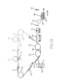
- FIGS. 22-24 illustrate an alternative 3-D electrostatic printing structure herein that includes a planar transfuse station 138 in place of the transfuse nip 130 shown in FIG. 1 .
- the planar transfuse station 138 is a planar portion of the ITB 110 that is between rollers 112 and is parallel to the platen 118 .
- FIG. 22 with this structure, when the platen 118 moves to contact the planar transfuse station 138 , all of the developed layer 102 is transferred simultaneously to the platen 118 or partially formed stack 106 , avoiding the rolling transfuses process shown in FIGS. 2 and 3 .
- FIG. 23 illustrates that the dispenser 142 dispenses leveling material 108
- FIG. 24 illustrates that the mechanical planer levels the leveling material 108 to keep the layers 102 within the stack 106 parallel with the upper surface 119 of the platen 118 , as discussed above.
- a drum 158 could be used in place of the ITB 110 , with all other components operating as described herein.
- the drum 158 could be an intermediate transfer surface receiving material from development stations 114 , 116 , as described above, or could be a photoreceptor and operate as the photoreceptor 256 described below operates, by maintaining a latent image of charge and receiving materials from development devices 254 .
- the dispenser 142 dispenses leveling material 108 and, as shown in FIG. 26 , the mechanical planer levels the leveling material 108 to keep the layers 102 within the stack 106 parallel with the upper surface 119 of the platen 118 , as discussed above.
- FIG. 27 illustrates many components of 3-D printer structures 204 herein.
- the 3-D printing device 204 includes a controller/tangible processor 224 and a communications port (input/output) 214 operatively connected to the tangible processor 224 and to a computerized network external to the printing device 204 .
- the printing device 204 can include at least one accessory functional component, such as a graphical user interface (GUI) assembly 212 .
- GUI graphical user interface
- the input/output device 214 is used for communications to and from the 3-D printing device 204 and comprises a wired device or wireless device (of any form, whether currently known or developed in the future).
- the tangible processor 224 controls the various actions of the printing device 204 .
- a non-transitory, tangible, computer storage medium device 210 (which can be optical, magnetic, capacitor based, etc., and is different from a transitory signal) is readable by the tangible processor 224 and stores instructions that the tangible processor 224 executes to allow the computerized device to perform its various functions, such as those described herein.
- a body housing has one or more functional components that operate on power supplied from an alternating current (AC) source 220 by the power supply 218 .
- the power supply 218 can comprise a common power conversion unit, power storage element (e.g., a battery, etc), etc.
- the 3-D printing device 204 includes at least one marking device (printing engine(s)) 240 that deposits successive layers of build and support material on a platen as described above, and are operatively connected to a specialized image processor 224 (that is different than a general purpose computer because it is specialized for processing image data). Also, the printing device 204 can include at least one accessory functional component (such as a scanner 232 ) that also operates on the power supplied from the external power source 220 (through the power supply 218 ).
- a marking device printing engine(s)
- a specialized image processor 224 that is different than a general purpose computer because it is specialized for processing image data.
- the printing device 204 can include at least one accessory functional component (such as a scanner 232 ) that also operates on the power supplied from the external power source 220 (through the power supply 218 ).
- the one or more printing engines 240 are intended to illustrate any marking device that applies build and support materials (toner, etc.) whether currently known or developed in the future and can include, for example, devices that use an intermediate transfer belt 110 (as shown in FIG. 28 ).
- each of the printing engine(s) 240 shown in FIG. 27 can utilize one or more potentially different (e.g., different color, different material, etc.) build material development stations 116 , one or more potentially different (e.g., different color, different material, etc.) support material development stations 114 , etc.
- the development stations 114 , 116 can be any form of development station, whether currently known or developed in the future, such as individual electrostatic marking stations, individual inkjet stations, individual dry ink stations, etc.
- Each of the development stations 114 , 116 transfers a pattern of material to the same location of the intermediate transfer belt 110 in sequence during a single belt rotation (potentially independently of a condition of the intermediate transfer belt 110 ) thereby, reducing the number of passes the intermediate transfer belt 110 must make before a full and complete image is transferred to the intermediate transfer belt 110 .
- FIG. 28 illustrates five development stations adjacent or in contact with a rotating belt ( 110 ), as would be understood by those ordinarily skilled in the art, such devices could use any number of marking stations (e.g., 2, 3, 5, 8, 11, etc.).
- Each of the individual electrostatic development stations 114 , 116 includes its own charging station 258 that creates a uniform charge on an internal photoreceptor 256 , an internal exposure device 260 that patterns the uniform charge into a latent image of charge, and an internal development device 254 that transfers build or support material to the photoreceptor 256 in a pattern matching the charge latent image.
- the pattern of build or support material is then drawn from the photoreceptor 256 to the intermediate transfer belt 110 by way of an opposite charge of the intermediate transfer belt 110 relative to the charge of the build or support material, that is usually created by a charge generator 128 on the opposite side of the intermediate transfer belt 110 .
- an additive manufacturing system for printing a 3-D part using electrophotography includes a photoconductor component having a surface, and a development station, where the development station is configured to developed layers of a material on the surface of the photoconductor component.
- the system also includes a transfer medium configured to receive the developed layers from the surface of the rotatable photoconductor component, and a platen configured to receive the developed layers from the transfer component in a layer-by-layer manner to print the 3-D part from at least a portion of the received layers.
- UV curable toners As disclosed in U.S. Pat. No. 7,250,238 it is known to provide a UV curable toner composition, as are methods of utilizing the UV curable toner compositions in printing processes.
- U.S. Pat. No. 7,250,238 discloses various toner emulsion aggregation processes that permit the generation of toners that in embodiments can be cured, that is by the exposure to UV radiation, such as UV light of has about 100 nm to about 400 nm.
- UV radiation such as UV light of has about 100 nm to about 400 nm.
- the toner compositions produced can be utilized in various printing applications such as temperature sensitive packaging and the production of foil seals.
- 7,250,238 embodiments relate to a UV curable toner composition comprised of an optional colorant, an optional wax, a polymer generated from styrene, and acrylate selected from the group consisting of butyl acrylate, carboxyethyl acrylate, and a UV light curable acrylate oligomer. Additionally, these aspects relate to a toner composition comprised of a colorant such as a pigment, an optional wax, and a polymer generated from a UV curable cycloaliphatic epoxide.
- U.S. Pat. No. 7,250,238 discloses a method of forming a UV curable toner composition
- a method of forming a UV curable toner composition comprising mixing a latex containing a polymer formed from styrene, butyl acrylate, a carboxymethyl acrylate, and a UV curable acrylate with a colorant and wax; adding flocculant to this mixture to optionally induce aggregation and form toner precursor particles dispersed in a second mixture; heating the toner precursor particles to a temperature equal to or higher than the glass transition temperature (Tg) of the polymer to form toner particles; optionally washing the toner particles; and optionally drying the toner particles.
- Tg glass transition temperature
- Computerized devices that include chip-based central processing units (CPU's), input/output devices (including graphic user interfaces (GUI), memories, comparators, tangible processors, etc.) are well-known and readily available devices produced by manufacturers such as Dell Computers, Round Rock Tex., USA and Apple Computer Co., Cupertino Calif., USA.
- Such computerized devices commonly include input/output devices, power supplies, tangible processors, electronic storage memories, wiring, etc., the details of which are omitted herefrom to allow the reader to focus on the salient aspects of the systems and methods described herein.
- printers, copiers, scanners and other similar peripheral equipment are available from Xerox Corporation, Norwalk, Conn., USA and the details of such devices are not discussed herein for purposes of brevity and reader focus.
- printer or printing device encompasses any apparatus, such as a digital copier, bookmaking machine, facsimile machine, multi-function machine, etc., which performs a print outputting function for any purpose.
- the details of printers, printing engines, etc. are well-known and are not described in detail herein to keep this disclosure focused on the salient features presented.
- the systems and methods herein can encompass systems and methods that print in color, monochrome, or handle color or monochrome image data. All foregoing systems and methods are specifically applicable to electrostatographic and/or xerographic machines and/or processes.
- the term fixing means the drying, hardening, polymerization, crosslinking, binding, or addition reaction or other reaction of the coating.
- terms such as “right”, “left”, “vertical”, “horizontal”, “top”, “bottom”, “upper”, “lower”, “under”, “below”, “underlying”, “over”, “overlying”, “parallel”, “perpendicular”, etc., used herein are understood to be relative locations as they are oriented and illustrated in the drawings (unless otherwise indicated). Terms such as “touching”, “on”, “in direct contact”, “abutting”, “directly adjacent to”, etc., mean that at least one element physically contacts another element (without other elements separating the described elements).
- the terms automated or automatically mean that once a process is started (by a machine or a user), one or more machines perform the process without further input from any user.
- the same identification numeral identifies the same or similar item.
Landscapes
- Engineering & Computer Science (AREA)
- Chemical & Material Sciences (AREA)
- Materials Engineering (AREA)
- Manufacturing & Machinery (AREA)
- Physics & Mathematics (AREA)
- General Physics & Mathematics (AREA)
- Mechanical Engineering (AREA)
- Optics & Photonics (AREA)
- Plasma & Fusion (AREA)
Priority Applications (5)
| Application Number | Priority Date | Filing Date | Title |
|---|---|---|---|
| US15/175,476 US10076869B2 (en) | 2016-06-07 | 2016-06-07 | Electrostatic 3-D printer using leveling material and mechanical planer |
| CN201710354765.9A CN107471637B (zh) | 2016-06-07 | 2017-05-18 | 使用整平材料和机械刨机的静电3-d打印机 |
| KR1020170061488A KR102159480B1 (ko) | 2016-06-07 | 2017-05-18 | 레벨링 재료 및 기계식 플래너를 이용하는 정전식 3-d 프린터 |
| JP2017099495A JP6796551B2 (ja) | 2016-06-07 | 2017-05-19 | 平坦化材料及び機械的プレーナーを使用した静電気式3dプリンタ |
| EP17174395.8A EP3255504B1 (en) | 2016-06-07 | 2017-06-02 | Electrostatic 3-d printer system using leveling material and mechanical planer |
Applications Claiming Priority (1)
| Application Number | Priority Date | Filing Date | Title |
|---|---|---|---|
| US15/175,476 US10076869B2 (en) | 2016-06-07 | 2016-06-07 | Electrostatic 3-D printer using leveling material and mechanical planer |
Publications (2)
| Publication Number | Publication Date |
|---|---|
| US20170348908A1 US20170348908A1 (en) | 2017-12-07 |
| US10076869B2 true US10076869B2 (en) | 2018-09-18 |
Family
ID=59009601
Family Applications (1)
| Application Number | Title | Priority Date | Filing Date |
|---|---|---|---|
| US15/175,476 Active 2036-08-11 US10076869B2 (en) | 2016-06-07 | 2016-06-07 | Electrostatic 3-D printer using leveling material and mechanical planer |
Country Status (5)
| Country | Link |
|---|---|
| US (1) | US10076869B2 (enExample) |
| EP (1) | EP3255504B1 (enExample) |
| JP (1) | JP6796551B2 (enExample) |
| KR (1) | KR102159480B1 (enExample) |
| CN (1) | CN107471637B (enExample) |
Cited By (5)
| Publication number | Priority date | Publication date | Assignee | Title |
|---|---|---|---|---|
| WO2021247154A1 (en) * | 2020-06-03 | 2021-12-09 | Sakuu Corporation | Jetted material printer with pressure-assisted fluid extraction |
| US11273608B2 (en) * | 2018-06-07 | 2022-03-15 | Sakuu Corporation | Multi-material three-dimensional printer |
| US11453162B2 (en) * | 2016-10-11 | 2022-09-27 | Xerox Corporation | System for finishing the surface of three-dimensional (3D) objects formed by additive manufacturing systems |
| WO2025057054A1 (en) * | 2023-09-11 | 2025-03-20 | Landa Labs (2012) Ltd | Method and apparatus for 3d printing |
| US12275187B2 (en) | 2020-06-03 | 2025-04-15 | Sakuu Corporation | 3D printer with pressure-assisted fluid extraction |
Families Citing this family (7)
| Publication number | Priority date | Publication date | Assignee | Title |
|---|---|---|---|---|
| US12046575B2 (en) | 2019-05-01 | 2024-07-23 | Io Tech Group Ltd. | Method to electrically connect chip with top connectors using 3D printing |
| US11446750B2 (en) | 2020-02-03 | 2022-09-20 | Io Tech Group Ltd. | Systems for printing solder paste and other viscous materials at high resolution |
| US11622451B2 (en) | 2020-02-26 | 2023-04-04 | Io Tech Group Ltd. | Systems and methods for solder paste printing on components |
| US11497124B2 (en) | 2020-06-09 | 2022-11-08 | Io Tech Group Ltd. | Methods for printing conformal materials on component edges at high resolution |
| US11691332B2 (en) | 2020-08-05 | 2023-07-04 | Io Tech Group Ltd. | Systems and methods for 3D printing with vacuum assisted laser printing machine |
| WO2023192591A1 (en) * | 2022-03-31 | 2023-10-05 | Evolve Additive Solutions, Inc. | Additive manufacturing materials and methods with improved color |
| US12005640B2 (en) * | 2022-06-03 | 2024-06-11 | Sakuu Corporation | Method and system of using gradual drying in multi-material 3D printing |
Citations (19)
| Publication number | Priority date | Publication date | Assignee | Title |
|---|---|---|---|---|
| US6066285A (en) | 1997-12-12 | 2000-05-23 | University Of Florida | Solid freeform fabrication using power deposition |
| US6775504B2 (en) | 2002-12-16 | 2004-08-10 | Xerox Corporation | Developer member adapted for depositing developer material on an imaging surface |
| US7250238B2 (en) | 2003-12-23 | 2007-07-31 | Xerox Corporation | Toners and processes thereof |
| US7270408B2 (en) | 2005-01-14 | 2007-09-18 | Xerox Corporation | Low level cure transfuse assist for printing with radiation curable ink |
| US20100121476A1 (en) | 2007-04-01 | 2010-05-13 | Kritchman Eliahu M | Method and system for three-dimensional fabrication |
| US7851549B2 (en) | 2007-12-13 | 2010-12-14 | Xerox Corporation | Curable polyester latex made by phase inversion emulsification |
| US20120276233A1 (en) | 2008-12-04 | 2012-11-01 | Objet Ltd. | Preparation of building material for solid freeform fabrication |
| WO2013044047A1 (en) | 2011-09-23 | 2013-03-28 | Stratasys, Inc. | Layer transfusion for additive manufacturing |
| US8470231B1 (en) | 2009-06-01 | 2013-06-25 | Stratasys Ltd. | Three-dimensional printing process for producing a self-destructible temporary structure |
| US8488994B2 (en) | 2011-09-23 | 2013-07-16 | Stratasys, Inc. | Electrophotography-based additive manufacturing system with transfer-medium service loops |
| US20130186558A1 (en) | 2011-09-23 | 2013-07-25 | Stratasys, Inc. | Layer transfusion with heat capacitor belt for additive manufacturing |
| US20140134334A1 (en) | 2012-11-09 | 2014-05-15 | Evonik Industries Ag | Multicolour extrusion-based 3d print process |
| US20150024169A1 (en) * | 2013-07-17 | 2015-01-22 | Stratasys, Inc. | Method for Printing 3D Parts and Support Structures with Electrophotography-Based Additive Manufacturing |
| US9017589B2 (en) | 2002-12-03 | 2015-04-28 | Stratasys Ltd. | Method for printing of three-dimensional objects |
| US20150142159A1 (en) | 2013-11-18 | 2015-05-21 | Kai-Jui Chang | Color or multi-material three-dimensional (3d) printing |
| US20150145174A1 (en) | 2013-11-22 | 2015-05-28 | Stratasys, Inc. | Magnetic platen assembly for additive manufacturing system |
| US20150266241A1 (en) * | 2014-03-18 | 2015-09-24 | Stratasys, Inc. | Electrophotography-Based Additive Manufacturing with Solvent-Assisted Planarization |
| US9193110B2 (en) | 2012-11-09 | 2015-11-24 | Evonik Industries Ag | Use and production of coated filaments for extrusion-based 3D printing processes |
| US20170299973A1 (en) * | 2016-04-18 | 2017-10-19 | Stratasys, Inc. | Electrophotography-based additive manufacturing with part molding |
Family Cites Families (5)
| Publication number | Priority date | Publication date | Assignee | Title |
|---|---|---|---|---|
| US6206672B1 (en) * | 1994-03-31 | 2001-03-27 | Edward P. Grenda | Apparatus of fabricating 3 dimensional objects by means of electrophotography, ionography or a similar process |
| JP2008225417A (ja) * | 2007-03-16 | 2008-09-25 | Fujitsu Ltd | 構造体の製造方法 |
| US8879957B2 (en) * | 2011-09-23 | 2014-11-04 | Stratasys, Inc. | Electrophotography-based additive manufacturing system with reciprocating operation |
| US10702453B2 (en) * | 2012-11-14 | 2020-07-07 | Xerox Corporation | Method and system for printing personalized medication |
| WO2017010457A1 (ja) * | 2015-07-14 | 2017-01-19 | 株式会社ミマキエンジニアリング | 造形装置及び造形方法 |
-
2016
- 2016-06-07 US US15/175,476 patent/US10076869B2/en active Active
-
2017
- 2017-05-18 CN CN201710354765.9A patent/CN107471637B/zh not_active Expired - Fee Related
- 2017-05-18 KR KR1020170061488A patent/KR102159480B1/ko not_active Expired - Fee Related
- 2017-05-19 JP JP2017099495A patent/JP6796551B2/ja not_active Expired - Fee Related
- 2017-06-02 EP EP17174395.8A patent/EP3255504B1/en active Active
Patent Citations (20)
| Publication number | Priority date | Publication date | Assignee | Title |
|---|---|---|---|---|
| US6066285A (en) | 1997-12-12 | 2000-05-23 | University Of Florida | Solid freeform fabrication using power deposition |
| US9017589B2 (en) | 2002-12-03 | 2015-04-28 | Stratasys Ltd. | Method for printing of three-dimensional objects |
| US6775504B2 (en) | 2002-12-16 | 2004-08-10 | Xerox Corporation | Developer member adapted for depositing developer material on an imaging surface |
| US7250238B2 (en) | 2003-12-23 | 2007-07-31 | Xerox Corporation | Toners and processes thereof |
| US7270408B2 (en) | 2005-01-14 | 2007-09-18 | Xerox Corporation | Low level cure transfuse assist for printing with radiation curable ink |
| US20100121476A1 (en) | 2007-04-01 | 2010-05-13 | Kritchman Eliahu M | Method and system for three-dimensional fabrication |
| US8784723B2 (en) | 2007-04-01 | 2014-07-22 | Stratasys Ltd. | Method and system for three-dimensional fabrication |
| US7851549B2 (en) | 2007-12-13 | 2010-12-14 | Xerox Corporation | Curable polyester latex made by phase inversion emulsification |
| US20120276233A1 (en) | 2008-12-04 | 2012-11-01 | Objet Ltd. | Preparation of building material for solid freeform fabrication |
| US8470231B1 (en) | 2009-06-01 | 2013-06-25 | Stratasys Ltd. | Three-dimensional printing process for producing a self-destructible temporary structure |
| US20130186558A1 (en) | 2011-09-23 | 2013-07-25 | Stratasys, Inc. | Layer transfusion with heat capacitor belt for additive manufacturing |
| US8488994B2 (en) | 2011-09-23 | 2013-07-16 | Stratasys, Inc. | Electrophotography-based additive manufacturing system with transfer-medium service loops |
| WO2013044047A1 (en) | 2011-09-23 | 2013-03-28 | Stratasys, Inc. | Layer transfusion for additive manufacturing |
| US20140134334A1 (en) | 2012-11-09 | 2014-05-15 | Evonik Industries Ag | Multicolour extrusion-based 3d print process |
| US9193110B2 (en) | 2012-11-09 | 2015-11-24 | Evonik Industries Ag | Use and production of coated filaments for extrusion-based 3D printing processes |
| US20150024169A1 (en) * | 2013-07-17 | 2015-01-22 | Stratasys, Inc. | Method for Printing 3D Parts and Support Structures with Electrophotography-Based Additive Manufacturing |
| US20150142159A1 (en) | 2013-11-18 | 2015-05-21 | Kai-Jui Chang | Color or multi-material three-dimensional (3d) printing |
| US20150145174A1 (en) | 2013-11-22 | 2015-05-28 | Stratasys, Inc. | Magnetic platen assembly for additive manufacturing system |
| US20150266241A1 (en) * | 2014-03-18 | 2015-09-24 | Stratasys, Inc. | Electrophotography-Based Additive Manufacturing with Solvent-Assisted Planarization |
| US20170299973A1 (en) * | 2016-04-18 | 2017-10-19 | Stratasys, Inc. | Electrophotography-based additive manufacturing with part molding |
Non-Patent Citations (1)
| Title |
|---|
| European Application No. 17174395.8, European Search Report dated Oct. 26, 2017, pp. 1-9. |
Cited By (9)
| Publication number | Priority date | Publication date | Assignee | Title |
|---|---|---|---|---|
| US11453162B2 (en) * | 2016-10-11 | 2022-09-27 | Xerox Corporation | System for finishing the surface of three-dimensional (3D) objects formed by additive manufacturing systems |
| US11273608B2 (en) * | 2018-06-07 | 2022-03-15 | Sakuu Corporation | Multi-material three-dimensional printer |
| US11504913B2 (en) * | 2018-06-07 | 2022-11-22 | Sakuu Corporation | Multi-material three-dimensional printer |
| WO2021247154A1 (en) * | 2020-06-03 | 2021-12-09 | Sakuu Corporation | Jetted material printer with pressure-assisted fluid extraction |
| US11260581B2 (en) | 2020-06-03 | 2022-03-01 | Sakuu Corporation | Jetted material printer with pressure-assisted fluid extraction |
| US11298875B2 (en) | 2020-06-03 | 2022-04-12 | Sakuu Corporation | Jetted material printer with pressure-assisted fluid extraction |
| CN115666904A (zh) * | 2020-06-03 | 2023-01-31 | 萨库公司 | 具有压力辅助流体提取的喷射材料打印机 |
| US12275187B2 (en) | 2020-06-03 | 2025-04-15 | Sakuu Corporation | 3D printer with pressure-assisted fluid extraction |
| WO2025057054A1 (en) * | 2023-09-11 | 2025-03-20 | Landa Labs (2012) Ltd | Method and apparatus for 3d printing |
Also Published As
| Publication number | Publication date |
|---|---|
| JP6796551B2 (ja) | 2020-12-09 |
| KR20170138342A (ko) | 2017-12-15 |
| US20170348908A1 (en) | 2017-12-07 |
| CN107471637A (zh) | 2017-12-15 |
| KR102159480B1 (ko) | 2020-09-25 |
| EP3255504A1 (en) | 2017-12-13 |
| EP3255504B1 (en) | 2019-09-04 |
| JP2017217904A (ja) | 2017-12-14 |
| CN107471637B (zh) | 2020-05-05 |
Similar Documents
| Publication | Publication Date | Title |
|---|---|---|
| US10076869B2 (en) | Electrostatic 3-D printer using leveling material and mechanical planer | |
| US11130282B2 (en) | Electrostatic 3-D development apparatus using cold fusing | |
| US10137634B2 (en) | Hybrid electrostatic 3-D printer using laser fusing | |
| US10195787B2 (en) | Electrostatic 3-D development apparatus using different melting point materials | |
| EP3231579B1 (en) | Electro-photographic 3-d printing using dissolvable paper | |
| US10086558B2 (en) | 3-D electrostatic printer using track bound platens and registration system | |
| US10040250B2 (en) | Electro-photographic 3-D printing using collapsible substrate | |
| US10350828B2 (en) | 3-D printing using intermediate transfer belt and curable polymers | |
| EP3243657B1 (en) | Electrostatic 3-d printer using addressable uv crosslinking | |
| US10279577B2 (en) | Electrostatic 3-D printer having rotating magnetic cores within developer rolls | |
| US10201930B2 (en) | Acoustic transfude 3-D printing | |
| US10213958B2 (en) | Electrostatic 3-D printing system having acoustic transfer and corotron |
Legal Events
| Date | Code | Title | Description |
|---|---|---|---|
| AS | Assignment |
Owner name: XEROX CORPORATION, CONNECTICUT Free format text: ASSIGNMENT OF ASSIGNORS INTEREST;ASSIGNORS:LIU, CHU-HENG;MCCONVILLE, PAUL J.;NOWAK, WILLIAM J.;AND OTHERS;SIGNING DATES FROM 20160427 TO 20160429;REEL/FRAME:038830/0827 |
|
| STCF | Information on status: patent grant |
Free format text: PATENTED CASE |
|
| MAFP | Maintenance fee payment |
Free format text: PAYMENT OF MAINTENANCE FEE, 4TH YEAR, LARGE ENTITY (ORIGINAL EVENT CODE: M1551); ENTITY STATUS OF PATENT OWNER: LARGE ENTITY Year of fee payment: 4 |
|
| AS | Assignment |
Owner name: CITIBANK, N.A., AS AGENT, DELAWARE Free format text: SECURITY INTEREST;ASSIGNOR:XEROX CORPORATION;REEL/FRAME:062740/0214 Effective date: 20221107 |
|
| AS | Assignment |
Owner name: XEROX CORPORATION, CONNECTICUT Free format text: RELEASE OF SECURITY INTEREST IN PATENTS AT R/F 062740/0214;ASSIGNOR:CITIBANK, N.A., AS AGENT;REEL/FRAME:063694/0122 Effective date: 20230517 |
|
| AS | Assignment |
Owner name: CITIBANK, N.A., AS COLLATERAL AGENT, NEW YORK Free format text: SECURITY INTEREST;ASSIGNOR:XEROX CORPORATION;REEL/FRAME:064760/0389 Effective date: 20230621 |
|
| AS | Assignment |
Owner name: JEFFERIES FINANCE LLC, AS COLLATERAL AGENT, NEW YORK Free format text: SECURITY INTEREST;ASSIGNOR:XEROX CORPORATION;REEL/FRAME:065628/0019 Effective date: 20231117 |
|
| AS | Assignment |
Owner name: XEROX CORPORATION, CONNECTICUT Free format text: TERMINATION AND RELEASE OF SECURITY INTEREST IN PATENTS RECORDED AT RF 064760/0389;ASSIGNOR:CITIBANK, N.A., AS COLLATERAL AGENT;REEL/FRAME:068261/0001 Effective date: 20240206 Owner name: CITIBANK, N.A., AS COLLATERAL AGENT, NEW YORK Free format text: SECURITY INTEREST;ASSIGNOR:XEROX CORPORATION;REEL/FRAME:066741/0001 Effective date: 20240206 |
|
| AS | Assignment |
Owner name: U.S. BANK TRUST COMPANY, NATIONAL ASSOCIATION, AS COLLATERAL AGENT, CONNECTICUT Free format text: FIRST LIEN NOTES PATENT SECURITY AGREEMENT;ASSIGNOR:XEROX CORPORATION;REEL/FRAME:070824/0001 Effective date: 20250411 |
|
| AS | Assignment |
Owner name: U.S. BANK TRUST COMPANY, NATIONAL ASSOCIATION, AS COLLATERAL AGENT, CONNECTICUT Free format text: SECOND LIEN NOTES PATENT SECURITY AGREEMENT;ASSIGNOR:XEROX CORPORATION;REEL/FRAME:071785/0550 Effective date: 20250701 |