US10070017B2 - Controlling synchronization between devices in a network - Google Patents
Controlling synchronization between devices in a network Download PDFInfo
- Publication number
- US10070017B2 US10070017B2 US14/390,803 US201314390803A US10070017B2 US 10070017 B2 US10070017 B2 US 10070017B2 US 201314390803 A US201314390803 A US 201314390803A US 10070017 B2 US10070017 B2 US 10070017B2
- Authority
- US
- United States
- Prior art keywords
- synchronization
- image data
- synchronization timing
- transmission
- network
- Prior art date
- Legal status (The legal status is an assumption and is not a legal conclusion. Google has not performed a legal analysis and makes no representation as to the accuracy of the status listed.)
- Active
Links
Images


Classifications
-
- H—ELECTRICITY
- H04—ELECTRIC COMMUNICATION TECHNIQUE
- H04N—PICTORIAL COMMUNICATION, e.g. TELEVISION
- H04N5/00—Details of television systems
- H04N5/04—Synchronising
- H04N5/06—Generation of synchronising signals
- H04N5/067—Arrangements or circuits at the transmitter end
-
- H—ELECTRICITY
- H04—ELECTRIC COMMUNICATION TECHNIQUE
- H04N—PICTORIAL COMMUNICATION, e.g. TELEVISION
- H04N21/00—Selective content distribution, e.g. interactive television or video on demand [VOD]
- H04N21/40—Client devices specifically adapted for the reception of or interaction with content, e.g. set-top-box [STB]; Operations thereof
- H04N21/41—Structure of client; Structure of client peripherals
- H04N21/4104—Peripherals receiving signals from specially adapted client devices
- H04N21/4126—The peripheral being portable, e.g. PDAs or mobile phones
-
- H—ELECTRICITY
- H04—ELECTRIC COMMUNICATION TECHNIQUE
- H04J—MULTIPLEX COMMUNICATION
- H04J3/00—Time-division multiplex systems
- H04J3/02—Details
- H04J3/06—Synchronising arrangements
- H04J3/0635—Clock or time synchronisation in a network
- H04J3/0685—Clock or time synchronisation in a node; Intranode synchronisation
-
- H—ELECTRICITY
- H04—ELECTRIC COMMUNICATION TECHNIQUE
- H04L—TRANSMISSION OF DIGITAL INFORMATION, e.g. TELEGRAPHIC COMMUNICATION
- H04L1/00—Arrangements for detecting or preventing errors in the information received
-
- H—ELECTRICITY
- H04—ELECTRIC COMMUNICATION TECHNIQUE
- H04N—PICTORIAL COMMUNICATION, e.g. TELEVISION
- H04N19/00—Methods or arrangements for coding, decoding, compressing or decompressing digital video signals
- H04N19/60—Methods or arrangements for coding, decoding, compressing or decompressing digital video signals using transform coding
- H04N19/61—Methods or arrangements for coding, decoding, compressing or decompressing digital video signals using transform coding in combination with predictive coding
Definitions
- the present technique relates to an information processing apparatus, a method, and a program, and more particularly, to an information processing apparatus, a method, and a program allowing for easily controlling video synchronization in image data transmission.
- the transmission of motion picture data requires timeliness (so-called real-time property). For example, when an image captured and obtained by an image-capturing device at a transmission source is displayed immediately (in so-called real-time manner) on an image display apparatus at a transmission destination, displaying of a motion picture may be corrupted if there is too much delay in encoding, transmission, decoding, and the like of image data. In such case, in order to ensure displaying of motion picture, it is required to manage the delay time in transmission of image data (including processing related to transmission such as encoding and decoding).
- Patent Document 1 JP 2007-311948 A
- Patent Document 2 JP 2009-278545 A
- Patent Document 3 JP 2008-028541 A
- Patent Document 4 Japanese Patent No. 3617087
- Patent Document 5 JP 2002-152162 A
- Patent Document 6 JP 2004-304809 A
- Ethernet registered trademark
- NGN Next Generation Network
- wireless network the bandwidth may become unstable, and the delay time is greatly affected.
- the network configuration is considered to change depending on circumstances such as disconnection of some of the circuits, and connection of a new circuit.
- the system configuration is highly flexible, so that a communication apparatus can be easily removed from the system, and a new communication apparatus can be easily added to the system.
- the present technique is made in view of such circumstances, and it is an object of the present technique to more easily control video synchronization in image data transmission.
- an information processing apparatus including a synchronization cancellation unit configured to cancel synchronization between synchronization timing of a network to which image data are transmitted and synchronization timing of the image data, on the basis of a delay time of image data transmission, an adjusting unit configured to adjust synchronization timing of the image data of which synchronization with the synchronization timing of the network is cancelled by the synchronization cancellation unit, and a synchronization connection unit configured to synchronize the synchronization timing of the image data, which is adjusted by the adjusting unit, with the synchronization timing of the network.
- the adjusting unit may advance the synchronization timing of the image data by a time equivalent to the delay time.
- the adjusting unit may initialize the encoding processing of the image data in the state where the synchronization between the synchronization timing of the image data and the synchronization timing of the network is cancelled by the synchronization cancellation unit.
- the adjusting unit may cause the encoding processing of the image data to be continued upon reducing a blank period of a frame of the image data so that the blank period is shorter than usual in the state where the synchronization between the synchronization timing of the image data and the synchronization timing of the network is cancelled by the synchronization cancellation unit.
- the information processing apparatus may further include a network synchronization acquisition unit configured to obtain the synchronization timing of the network with the other party in communication in the state where the synchronization between the synchronization timing of the image data and the synchronization timing of the network is cancelled by the synchronization cancellation unit.
- a network synchronization acquisition unit configured to obtain the synchronization timing of the network with the other party in communication in the state where the synchronization between the synchronization timing of the image data and the synchronization timing of the network is cancelled by the synchronization cancellation unit.
- the information processing apparatus may further include a measuring unit configured to measure the delay time, and the synchronization cancellation unit may cancel the synchronization between the synchronization timing of the network to which the image data are transmitted and the synchronization timing of the image data, on the basis of the delay time measured by the measuring unit.
- the measuring unit may determine a transmission source in accordance with a synchronization control topology and a network setting, and may measure the delay period using image data transmitted from the transmission source.
- the information processing apparatus may further include a transmission unit configured to transmit the image data in accordance with the synchronization timing of the image data synchronized with the synchronization timing of the network by the synchronization connection unit.
- an information processing method for an information processing apparatus wherein the information processing apparatus cancels synchronization between synchronization timing of a network to which image data are transmitted and synchronization timing of the image data, on the basis of a delay time of image data transmission, and the information processing apparatus adjusts synchronization timing of the image data of which synchronization with the synchronization timing of the network is cancelled, and the information processing apparatus synchronizes the synchronization timing of the image data, which is adjusted, with the synchronization timing of the network.
- a program for causing a computer to function as a synchronization cancellation unit configured to cancel synchronization between synchronization timing of a network to which image data are transmitted and synchronization timing of the image data, on the basis of a delay time of image data transmission, an adjusting unit configured to adjust synchronization timing of the image data of which synchronization with the synchronization timing of the network is cancelled by the synchronization cancellation unit, and a synchronization connection unit configured to synchronize the synchronization timing of the image data, which is adjusted by the adjusting unit, with the synchronization timing of the network.
- an information processing apparatus in a system including a first video transmission sequence having a video synchronization acquisition function and a second video transmission sequence, and the information processing apparatus includes a synchronization cancellation unit configured to cancel synchronization between synchronization timing of a network to which image data are transmitted and synchronization timing of the image data, on the basis of a delay time of image data transmission according to the first video transmission sequence, an adjusting unit configured to adjust synchronization timing of the image data of which synchronization with the synchronization timing of the network is cancelled by the synchronization cancellation unit, a synchronization connection unit configured to synchronize the synchronization timing of the image data, which is adjusted by the adjusting unit, with the synchronization timing of the network, and a control unit configured to operate the second video transmission sequence different from the first video transmission sequence, using synchronization timing generated from the first video transmission sequence.
- the adjusting unit may advance the synchronization timing of the image data by a time equivalent to the delay time.
- the adjusting unit may initialize the encoding processing of the image data in the state where the synchronization between the synchronization timing of the image data and the synchronization timing of the network is cancelled by the synchronization cancellation unit.
- the adjusting unit may cause the encoding processing of the image data to be continued upon reducing a blank period of a frame of the image data so that the blank period is shorter than usual in the state where the synchronization between the synchronization timing of the image data and the synchronization timing of the network is cancelled by the synchronization cancellation unit.
- the information processing apparatus may further include a network synchronization acquisition unit configured to obtain the synchronization timing of the network with the other party in communication in the state where the synchronization between the synchronization timing of the image data and the synchronization timing of the network is cancelled by the synchronization cancellation unit.
- a network synchronization acquisition unit configured to obtain the synchronization timing of the network with the other party in communication in the state where the synchronization between the synchronization timing of the image data and the synchronization timing of the network is cancelled by the synchronization cancellation unit.
- the information processing apparatus may further include a measuring unit configured to measure the delay time, and the synchronization cancellation unit may cancel the synchronization between the synchronization timing of the network to which the image data are transmitted and the synchronization timing of the image data, on the basis of the delay time measured by the measuring unit.
- the measuring unit may determine a transmission source for the first video transmission sequence in accordance with a synchronization control topology and a network setting, and may measure the delay period using image data transmitted from the transmission source.
- the information processing apparatus may further include a transmission unit configured to transmit the image data in accordance with the synchronization timing of the image data synchronized with the synchronization timing of the network by the synchronization connection unit.
- an information processing method for an information processing apparatus in a system including a first video transmission sequence having a video synchronization acquisition function and a second video transmission sequence, wherein the information processing apparatus cancels synchronization between synchronization timing of a network to which image data are transmitted and synchronization timing of the image data, on the basis of a delay time of image data transmission according to the first video transmission sequence, and the information processing apparatus adjusts synchronization timing of the image data of which synchronization with the synchronization timing of the network is cancelled, and the information processing apparatus synchronizes the synchronization timing of the image data, which is adjusted, with the synchronization timing of the network, and the information processing apparatus operates the second video transmission sequence different from the first video transmission sequence, using synchronization timing generated from the first video transmission sequence.
- a program for a computer in a system including a first video transmission sequence having a video synchronization acquisition function and a second video transmission sequence, wherein the program causes the computer to function as a synchronization cancellation unit configured to cancel synchronization between synchronization timing of a network to which image data are transmitted and synchronization timing of the image data, on the basis of a delay time of image data transmission according to the first video transmission sequence, an adjusting unit configured to adjust synchronization timing of the image data of which synchronization with the synchronization timing of the network is cancelled by the synchronization cancellation unit, a synchronization connection unit configured to synchronize the synchronization timing of the image data, which is adjusted by the adjusting unit, with the synchronization timing of the network, and a control unit configured to operate the second video transmission sequence different from the first video transmission sequence, using synchronization timing generated from the first video transmission sequence.
- synchronization between synchronization timing of a network to which image data are transmitted and synchronization timing of the image data is cancelled on the basis of a delay time of image data transmission, and synchronization timing of the image data of which synchronization with the synchronization timing of the network is cancelled is adjusted, and the synchronization timing of the image data, which is adjusted, is synchronized with the synchronization timing of the network.
- synchronization between synchronization timing of a network to which image data are transmitted and synchronization timing of the image data is cancelled on the basis of a delay time of image data transmission according to the first video transmission sequence, and synchronization timing of the image data of which synchronization with the synchronization timing of the network is cancelled by the synchronization cancellation unit is adjusted, and the synchronization timing of the image data, which is adjusted, is synchronized with the synchronization timing of the network, and the second video transmission sequence different from the first video transmission sequence is caused to operate using synchronization timing generated from the first video transmission sequence.
- information can be processed.
- video synchronization in image data transmission can be controlled more easily.
- FIG. 1 is a block diagram illustrating an example of a main configuration of an image transmission system.
- FIG. 2 is a figure illustrating an example of a system timing configuration.
- FIG. 3 is a block diagram illustrating an example of a main configuration of the image transmission system.
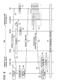
- FIG. 4 is a figure illustrating an example of the system timing configuration.
- FIG. 5 is a figure for illustrating the details of the system timing.
- FIG. 6 is a figure for explaining an example of a flow of processing associated with image data transmission/reception.
- FIG. 7 is a figure continued from FIG. 6 for explaining the example of the flow of processing associated with the image data transmission/reception.
- FIG. 8 is a figure for explaining another example of a flow of processing associated with the image data transmission/reception.
- FIG. 9 is a figure continuous to FIG. 8 for explaining another example of a flow of processing associated with the image data transmission/reception.
- FIG. 10 is a flowchart for explaining an example of flow of initial synchronization processing.
- FIG. 11 is a flowchart for explaining an example of flow of re-synchronization processing.
- FIG. 12 is a flowchart continued from FIG. 11 for explaining an example of a flow of re-synchronization processing.
- FIG. 13 is a flowchart for explaining another example of a flow of initial synchronization processing.
- FIG. 15 is a flowchart continued from FIG. 14 for explaining another example of a flow of re-synchronization processing.
- FIG. 16 is a figure for explaining an example of system configuration change.
- FIGS. 17A to 17C are figures for explaining another example of a system configuration change.
- FIG. 18 is a flowchart for explaining an example of flow of determination processing.
- FIGS. 19A and 19B are figures illustrating an example of a delay ratio in data transmission.
- FIGS. 20A and 20B are figures illustrating a typical example of configuration of an image transmission system to which the present technique is applied, and illustrating an example of a delay ratio thereof.
- FIG. 21 is a figure illustrating a typical example of configuration of the image processing system to which the present technique is applied.
- FIG. 22 is a block diagram illustrating a typical example of configuration of an image-capturing device.
- FIG. 23 is a figure illustrating an example of an FEC block.
- FIG. 24 is a figure for explaining an example of configuration of a packet.
- FIG. 25 is a flowchart for explaining an example of a flow of transmission processing.
- FIG. 26 is a flowchart for explaining an example of a flow of reception processing.
- FIG. 27 is a block diagram illustrating a typical example of configuration of a coding unit.
- FIG. 28 is a block diagram illustrating a typical example of configuration of a wavelet transformation unit.
- FIG. 29 is a figure illustrating a typical example of configuration of a sub band of a transformation coefficient.
- FIG. 30 is a figure illustrating an example of line blocks.
- FIG. 31 is a block diagram illustrating a typical example of configuration of a decoding unit.
- FIG. 32 is a flowchart for explaining an example of a flow of encoding processing.
- FIG. 33 is a flowchart for explaining an example of a flow of decoding processing.
- FIG. 34 is a block diagram illustrating a typical example of configuration of a computer.
- Embodiments for carrying out the present disclosure (hereinafter referred to as embodiments) will be hereinafter explained. The explanation will be made in the following order.
- FIG. 1 is a block diagram illustrating an example of a main configuration of an image transmission system.
- An image transmission system 10 as shown in FIG. 1 includes a transmission apparatus 11 and a reception apparatus 12 , and is a system for transmitting encoded data, which are obtained by encoding image data, from the transmission apparatus 11 to the reception apparatus 12 .
- FIG. 1 shows a configuration of synchronization of the transmission apparatus 11 and the reception apparatus 12 .
- the transmission apparatus 11 includes an image time management unit 21 and a network transmission time management unit 22 .
- the reception apparatus 12 includes an image time management unit 31 and a network transmission time management unit 32 .
- the image time management unit 21 and the image time management unit 31 manage synchronization of image display such as vertical synchronization and horizontal synchronization of image data.
- the network transmission time management unit 22 and the network transmission time management unit 32 perform synchronization control of a network circuit, and synchronization control of transmission of image data.
- one of the network transmission time management unit 22 and the network transmission time management unit 32 becomes STAY
- the other of the network transmission time management unit 22 and the network transmission time management unit 32 becomes Follower.
- the unit serving as STAY predominantly performs the synchronization control.
- the follower follows the STAY's synchronization control.
- FIG. 2 is a figure illustrating an example of a system timing configuration of the image transmission system 10 of FIG. 1 .
- the synchronization management of the video transmission and the network circuit are done by the network transmission time management unit 22 and the network transmission time management unit 32 , and therefore, the direction of control in the synchronization management of video transmission and the direction of control in the synchronization management of the network circuit are limited to the same direction as each other as shown in the example of FIG. 2 .
- the transmission apparatus 11 is STAY, and the reception apparatus 12 is the Follower
- the transmission apparatus 11 is also STAY and the reception apparatus 12 is also Follower in the synchronization management of the network circuit (“network” in the table of FIG. 2 ).
- a method for performing the synchronization management of the video transmission completely separately from the synchronization management of the network circuit may be considered. But in such case, it has been difficult to maintain synchronization between the time management of the video transmission and the time management of the network circuit, and it may has been difficult to perform data transmission with a shorter delay.
- the synchronization control of the video transmission is performed separately from the synchronization management of the network circuit, and further, the synchronization control of the video transmission and the synchronization management of the network circuit can be controlled to be in cooperation (synchronization connection) or independent (synchronization cancellation).
- FIG. 3 is a block diagram illustrating an example of a main configuration of an image transmission system.
- the image transmission system 100 as shown in FIG. 3 is a communication system to which the present technique is applied.
- the image transmission system 100 includes a transmission apparatus 101 and a reception apparatus 102 , and is a system for transmitting encoded data, which are obtained by encoding image data, from the transmission apparatus 101 to the reception apparatus 102 .
- FIG. 3 shows a configuration of synchronization of the transmission apparatus 101 and the reception apparatus 102 .
- the transmission apparatus 101 includes an image time management unit 111 , a transmission time management unit 112 , and a network transmission time management unit 113 .
- the reception apparatus 102 includes an image time management unit 121 , a transmission time management unit 122 , and a network transmission time management unit 123 .
- the image time management unit 111 and the image time management unit 121 manage the synchronization timing of the image such as vertical synchronization and horizontal synchronization of image data.
- the transmission time management unit 112 and the transmission time management unit 122 manage synchronization timing for transmission of image data and manage synchronization timing for processing of encoding and decoding of image data (for compression).
- the network transmission time management unit 113 and the network transmission time management unit 123 performs the synchronization control of the network circuit.
- the synchronization timing for compression is controlled to perform the encoding processing and the decoding processing so as to more greatly reduce the amount of delay of the entire data transmission including various kinds of amounts of delay as shown in FIG. 5 .
- the management of the synchronization timing of the transmission is done on the basis of the synchronization information about the network circuit. Further, the management of the synchronization timing of the image is performed with the same accuracy of time as the management of the synchronization timing of the transmission. As described above, the management of the synchronization timing of the image and the management of the synchronization timing of the transmission are performed by processing units different from each other. However, when the synchronization timing is set, the synchronization timing continues to operate with the same phase.
- the management of the synchronization timing of the transmission may be associated with the management of the synchronization timing of the network circuit, or the association thereof may be cancelled. For example, only the synchronization timing of the transmission can be changed. This change may be made slowly, or may be made instantly. It should be noted that the “transmission” of the synchronization timing of the transmission includes not only transmission of video (image data) but also transmission of sound (sound data).
- the transmission time management unit 112 and the transmission time management unit 122 separate the synchronization timing of the transmission and the synchronization timing of the network circuit are separated from each other, and the association therebetween is cancelled. Accordingly, the synchronization timing of the transmission runs freely. At this occasion, the synchronization timing of the image and the synchronization timing of the transmission may still be the same phase.
- the transmission time management unit 112 and the transmission time management unit 122 associate the synchronization timing of the transmission with the synchronization timing of the network circuit.
- the transmission time management unit 112 and the transmission time management unit 122 exchange the synchronization information with the network transmission time management unit 113 and the network transmission time management unit 123 , and associate the synchronization timing of the transmission with the synchronization timing of the network circuit.
- the synchronization timing of the network circuit and the synchronization timing of the transmission can be easily separated from each other and can be easily associated with each other. Therefore, for example, the synchronization control unit of the network circuit can operate normally regardless of whether it is at the transmission side or at the reception side.
- the transmission time management unit 122 (STA 2 ) of the reception apparatus 102 is STAY (Stay) and the transmission time management unit 112 (STA 1 ) of the transmission apparatus 101 is Follower (Timing Follower) in the video transmission synchronization (Video synchronization)
- the STAY of the synchronization (network) of the network circuit may be either STA 1 or STA 2 .
- a camera and a CCU are connected by a composite cable called an optical fiber cable, a triax cable, or a multi-cable, but when a generally-available circuit such as Ethernet (registered trademark), NGN (Next Generation Network), and wireless network is supported, the generally-available circuit is extremely cheaper than dedicated circuits and satellite links, and therefore, the live broadcast system can be structured at a low cost.
- a generally-available circuit such as Ethernet (registered trademark), NGN (Next Generation Network), and wireless network
- the video synchronization can be controlled, and an activation sequence can be structured with a simple configuration.
- GenLock of cameras can be made via an asynchronous network, and therefore, even when simultaneous live broadcast is made using multiple relay control stations and multiple cameras, high quality camera images can be transmitted with a shorter delay using the same activation sequence.
- initial synchronization processing which is synchronization processing that is performed when the data transmission is started
- re-synchronization processing which is synchronization processing that is performed during the data transmission. How the processing is performed will be shown in FIGS. 6 to 9 .
- FIGS. 6 to 7 show a case where the network management unit which is STAY of the synchronization management of the network circuit is at the side of the reception apparatus, and the network reception unit which is Follower is at the side of the transmission apparatus.
- STAY of the synchronization management for the transmission is at the side of the reception apparatus which receives images
- Follower is at the side of the transmission apparatus which transmits images. More specifically, in the synchronization management of the network circuit and the synchronization management for the transmission, the directions of STAY and Follower are the same as each other. The details of FIGS. 6 and 7 will be explained later.
- FIGS. 8 and 9 show a case where the network management unit which is STAY of the synchronization management of the network circuit is at the side of the transmission apparatus, and the network reception unit which is Follower is at the side of the reception apparatus.
- STAY of the synchronization management for the transmission is at the side of the reception apparatus that receives images
- Follower is at the side of the transmission apparatus that transmits images. More specifically, in the synchronization management of the network circuit and the synchronization management for the transmission, the directions of STAY and Follower are opposite to each other. The details of FIGS. 8 and 9 will be explained later.
- STAY of the synchronization management of the network circuit may be at the side of the transmission, or may be at the side of the reception.
- step S 101 the transmission apparatus 101 obtains the time synchronization of the network circuit on the basis of the management of the network transmission time management unit 113 (processing 152 to processing 158 in the case of FIG. 6 , and processing 201 to processing 207 , processing 209 in the case of FIG. 8 ). Techniques such as GPS and IEEE1588 are available in order to achieve this function.
- step S 102 the transmission apparatus 101 starts image input.
- the timing of this processing may be any given timing.
- the initial value which is set in step S 103 is determined.
- step S 103 the transmission apparatus 101 initializes the image compression encoder. It should be noted that the setting value of the initialization may be determined regardless of presence/absence of this processing.
- step S 104 the transmission apparatus 101 starts compression of image data received.
- step S 105 the transmission apparatus 101 starts video transmission on the basis of the management of the transmission time management unit 112 , and transmits encoded data, which are obtained by encoding image data, to the reception apparatus 102 via a network including a generally-available circuit (processing 160 in the case of FIG. 6 , and processing 211 in the case of FIG. 8 ).
- step S 106 the transmission time management unit 112 sets a delay offset amount which is found in advance. For example, the value which has been set in advance is saved (processing 151 in the case of FIG. 6 , and processing 208 in the case of FIG. 8 ), and the saved value is reset (processing 168 in the case of FIG. 6 , and processing 220 in the case of FIG. 8 ). With this processing, the transmission apparatus 101 can reduce the time it takes to perform the initial synchronization.
- the processing in step S 106 is not limited to the order of sequence as shown in FIG. 10 . For example, the processing may be performed before the position of step S 106 of FIG. 10 .
- step S 107 the transmission time management unit 112 waits until receiving the notification of the measurement result of the delay offset amount from the reception apparatus 102 .
- the processing in step S 108 is subsequently performed.
- step S 108 in accordance with the control of the transmission time management unit 112 , the transmission apparatus 101 once stops the input video in order to change the timing of VSYNC and HSYNC which are timing signals of the video, and release synchronization between the video synchronization and the network synchronization (processing 165 in the case of FIG. 6 , and processing 216 in the case of FIG. 8 ).
- the video compression encoder may not receive video data known in advance, and therefore, the video compression encoder may not temporarily operate normally. For this reason, a function may be provided to allow for timing of VSYNC and HSYNC with a frequency shift as much as what the video compression encoder can tolerate.
- step S 109 the transmission time management unit 112 for changing the synchronization acquisition position (SYNC position) (processing 166 in the case of FIG. 6 , and processing 217 in the case of FIG. 8 ).
- the transmission time management unit 112 resets the video input timing by the transmission time management unit 112 on the basis of the amount of offset delay notified by the reception apparatus 102 in step S 110 (processing 192 in the case of FIG. 6 , and processing 242 in the case of FIG. 8 ). It should be noted that the network synchronization is maintained during this period.
- step S 111 the transmission apparatus 101 resumes the video input with the amount of delay based on the measurement result, and synchronizes the video synchronization and the network synchronization.
- the transmission apparatus 101 terminates the correction processing of the video synchronization, and indicates the state in which the environment for starting the video transmission is ready.
- a function is provided to be capable of handling disrupted video data or change in the interval of VSYNC, HSYNC, then, it is not necessary to reset.
- step S 112 the transmission apparatus 101 starts the video transmission (processing 174 in the case of FIG. 7 , and processing 234 in the case of FIG. 9 ).
- step S 113 the transmission apparatus 101 controlled by the transmission time management unit 112 corrects the amount of offset delay by a very small level, and copes with the change in the very small level. More specifically, in this processing, the transmission apparatus 101 performs operation for correcting the offset amount so as to satisfy the specification of standard specification video input/output interfaces such as HD-SDI, 3D-SDI, HDMI (registered trademark), and Display Port (processing 177 , processing 180 , and processing 181 (which is processing 194 ) in the case of FIG. 7 , and processing 237 to processing 239 (which is processing 243 ) in the case of FIG. 9 ).
- standard specification video input/output interfaces such as HD-SDI, 3D-SDI, HDMI (registered trademark), and Display Port
- step S 114 the transmission apparatus 101 checks whether or not the transmission apparatus 101 receives a command of the amount of offset delay from the reception apparatus 102 .
- the processing in step S 113 is performed again, and processing subsequent thereto is repeated.
- the initial operation processing is terminated.
- the transmission apparatus 101 slightly corrects the transmission time management according to the command given by the reception apparatus 102 in order to correct a very small deviation of synchronization between the transmission and the reception even during the video transmission.
- step S 131 the transmission apparatus 101 obtains a re-synchronization request from the reception apparatus 102 .
- the synchronization of the network circuit has been finished.
- step S 132 the transmission apparatus 101 determines whether the current synchronization relationship is different from synchronization relationship after the network circuit topology is changed, and it is necessary to re-synchronize the video transmission or not. When the re-synchronization is not necessary, the re-synchronization processing is terminated.
- step S 133 When the re-synchronization is necessary, the processing in step S 133 is subsequently performed.
- step S 133 the transmission apparatus 101 controlled by the transmission time management unit 112 re-synchronizes the video transmission to solve the state in which the current synchronization of the video transmission is not correct (Error state).
- step S 134 the transmission apparatus 101 determines whether to initialize the entire system.
- the processing in step S 141 of FIG. 12 is subsequently performed.
- step S 135 is subsequently performed.
- step S 135 the transmission apparatus 101 controlled by the network transmission time management unit 113 determines whether to re-activate the network circuit or not.
- the processing in step S 136 is subsequently performed.
- step S 136 the transmission apparatus 101 controlled by the network transmission time management unit 113 initializes the synchronization information about the network circuit.
- the processing in step S 142 of FIG. 12 is subsequently performed.
- step S 137 is subsequently performed.
- step S 137 the transmission apparatus 101 controlled by the transmission time management unit 112 initializes the synchronization timing of the video transmission. More specifically, the encoding processing of the image data is initialized. When the processing in step S 137 is finished, the processing in step S 143 of FIG. 12 is subsequently performed. Instead of initializing the encoding processing of the image data, the blank period of a frame of image data may be configured to be shorter than the normal, and the encoding processing of the image data may be continued.
- step S 141 to step S 152 of FIG. 12 is executed in the same manner as each processing in step S 103 to step S 114 of FIG. 10 .
- step S 152 the offset and the amount of network delay are determined to be the same, the processing in FIG. 11 is performed again, and the re-synchronization processing is terminated.
- the transmission apparatus 101 achieves each processing in FIG. 6 to FIG. 9 .
- the reception apparatus 102 performs each processing in step S 201 to step S 203 in the same manner as each processing in step S 101 to step S 103 of FIG. 10 .
- the network circuit acquires synchronization as the result of the processing in step S 201 , so that the time management controlling the network circuit notifies the same temporal timing as the transmission with regard to the transmission time management unit 112 (processing 162 in the case of FIG. 6 , and processing 213 in the case of FIG. 8 ).
- the time management at the transmission side is advance by the amount of offset delay which is set by the transmission side.
- step S 204 the reception apparatus 102 receives a packet transmitted from the transmission apparatus 101 , and starts processing for correcting the network circuit error.
- the amount of delay of the network circuit between the transmission and the reception is still being measured, and therefore, in order to avoid video disruption, video decoding is not started.
- the amount of delay of each processing is reduced as much as possible, and therefore, if the video is displayed even though there is an uncertain factor such as the amount of delay of the network circuit, the video is likely to be disrupted.
- step S 205 the reception apparatus 102 starts reception of video data at a time determined by the processing in step S 204 . However, in this state, the video is still not displayed.
- step S 206 the reception apparatus 102 compares the difference between the time stamp value added to a packet of video data received and the time stamp value possessed by the reception apparatus 102 .
- the time stamp value is such that the time stamp is operated at a time level obtained temporarily in step S 204 , and immediately before the video data are transmitted as packets, the time stamp is added.
- Step S 207 is a step for causing the reception apparatus 102 to perform statistics processing of the difference information, and by calculating the amount of delay between the transmission and the reception, how much amount the transmission side is offset is obtained (processing 163 (processing 191 ) in the case of FIG. 6 , and processing 214 (processing 241 ) in the case of FIG. 8 ).
- step S 208 the reception apparatus 102 determines whether the offset amount is problematic as the entire system. When the offset amount is not problematic, the processing in step S 209 is subsequently performed.
- step S 209 the reception apparatus 102 writes the amount of offset delay, which is calculated for subsequent activation, to the nonvolatile memory.
- the processing in step S 209 is finished, the processing in step S 205 is performed again.
- step S 208 when the amount of offset delay is determined not to be problematic, the processing in step S 210 is subsequently performed.
- the reception apparatus 102 obtains the synchronization for the video transmission (processing 172 in the case of FIG. 7 , and processing 232 in the case of FIG. 9 ).
- step S 211 the reception apparatus 102 has such system setting that the video is not disrupted even when it is displayed, and therefore, the display of the video is turned on (processing 173 in the case of FIG. 7 , and processing 233 in the case of FIG. 9 ).
- step S 212 the reception apparatus 102 starts the video reception (processing 174 in the case of FIG. 7 , and processing 234 in the case of FIG. 9 ).
- step S 212 When the processing in step S 212 is finished, the initial synchronization processing is terminated.
- the reception apparatus 102 When the re-synchronization processing is started, the reception apparatus 102 performs the same processing as step S 206 of FIG. 13 in step S 231 , and monitors to determine whether the synchronization timing is the same as that of the initial synchronization.
- step S 232 the reception apparatus 102 determines whether the re-synchronization is necessary or not. When the reception apparatus 102 determines that the reception apparatus 102 does not need to perform the re-synchronization, the processing in step S 231 is performed again.
- step S 232 when the reception apparatus 102 determines that the reception apparatus 102 needs to perform the re-synchronization, the processing in step S 233 is subsequently performed.
- step S 233 to step S 237 is executed in the same manner as each processing in step S 133 to step S 137 of FIG. 11 .
- the processing in step S 241 of FIG. 15 is subsequently performed.
- the processing in step S 242 of FIG. 15 is subsequently performed.
- the processing in step S 243 of FIG. 15 is subsequently performed.
- step S 241 to step S 250 of FIG. 15 is performed in the same manner as each processing in step S 203 to step S 212 of FIG. 13 .
- the reception apparatus 102 achieves each processing in FIGS. 6 to 9 .
- the transmission apparatus 101 and the reception apparatus 102 can easily perform the synchronization control in the same manner regardless of whether STAY of the synchronization management of the network circuit and STAY of the synchronization management for the transmission are the same or are different.
- FIG. 16 is a figure for explaining an example of system configuration change.
- a system for transmitting video from a communication apparatus STA 1 to a communication apparatus STA 2 For example, in a star-type network environment as shown in FIG. 16 , a system for transmitting video from a communication apparatus STA 1 to a communication apparatus STA 2 .
- images are transmitted between the communication apparatus STA 1 and the communication apparatus STA 2 , and suppose that, during the image transfer, a new communication apparatus STA 3 and a new communication apparatus STA 4 are connected to the system.
- the network management unit is the communication apparatus STA 1 when the service starts in the star-type topology (Case 1 ).
- the star-type topology (Case 1 ).
- exchange of image transmission procedure between STA 1 and STA 2 is as shown in FIGS. 8 and 9 .
- the transmission apparatus 101 and the reception apparatus 102 of the image transmission system 100 find the change of the topology, and can easily change the transfer processing procedure in accordance with the network management unit to be changed.
- the network management unit is not limited to the present embodiment.
- the network management unit of each link may be changed in response to not only the change of the topology but also network load, topology, and network traffic that changes every moment.
- FIGS. 17A to 17C are figures for explaining another example of a system configuration change.
- a system for transmitting video from STA 1 to STA 2 will be considered.
- STA 1 is selected as the network management unit (STA) between STA 1 and STA 3
- STA 1 is selected as the network management unit (STA) between STA 1 and STA 4
- STA 3 is selected as the network management unit (STA) between STA 3 and STA 4
- STA 3 is selected as the network management unit (STA) between STA 3 and STA 2
- STA 4 is selected as the network management unit (STA) between STA 4 and STA 2 .
- the transmission path from STA 1 to STA 2 may be Case 1 or Case 2 .
- Network path selection method includes Proactive method and Reactive method, but in the present embodiment, using the Proactive method, first, the path selection is set as Case 1 . It should be noted that the path selection and the time management of the network management unit are considered to be different from each other.
- the exchange of the image transmission procedure between STA 3 and STA 4 is as shown in FIGS. 8 and 9 .
- the path selection is done according to the Proactive method, and this time, suppose that Case 2 is selected.
- the image transfer procedure according to FIG. 17 is performed.
- the transfer processing procedure can be changed according to the selected transmission path even in the same topology.
- the network management unit is not limited to the present embodiment.
- the network management unit of each link may be changed in response to not only the change of the topology but also network load, topology, and network traffic that changes every moment.
- the Proactive method has been explained as an example of network path selection method.
- the network path selection method may be Reactive method. Still alternatively, both of them may be used.
- a determination as to the synchronization control of the network circuit may be made as to whether the unit in question is configured to be STAY or follower.
- the transmission apparatus 101 finds the other party in communication, which is connected to the network in step S 301 .
- the transmission apparatus 101 exchanges information about the network management with the other party in communication.
- the transmission apparatus 101 determines whether the transmission apparatus 101 is to be STAY or not in the synchronization of the network circuit in step S 303 .
- the processing in step S 304 is subsequently performed.
- step S 304 the transmission apparatus 101 sets the network synchronization to STAY.
- the determination processing is terminated.
- step S 303 when the transmission apparatus 101 determines that the transmission apparatus 101 is not to be STAY, the processing in step S 305 is subsequently performed.
- step S 305 the transmission apparatus 101 sets the network synchronization to Follower.
- the determination processing is terminated.
- the transmission apparatus 101 can flexibly configure the setting of STAY (Follower) in accordance with the change of the system configuration.
- the processing is executed by the reception apparatus 102 , basically the same processing as the processing performed where the transmission apparatus 101 executes the processing. More specifically, like the transmission apparatus 101 , the reception apparatus 102 can also flexibly configure the setting of STAY (Follower) in accordance with the change of the system configuration.
- the synchronization control explained above may be applied to any system as long as it is a system for transmitting image data.
- this can also be applied to a system for performing delay control of FEC processing so as to more greatly reduce the amount of delay as explained below.
- the amount of data is reduced by encoding (compression) processing at the transmission side and the reduced data are transmitted to the network, and then the reception side performs decoding (extraction) processing on the encoded reception data to reproduce the data.
- MPEG Motion Picture Experts Group
- IP Internet Protocol
- the MPEG stream is received using a communication terminal such as a PC (Personal Computer), a PDA (Personal Digital Assistants), and a cellular phone, and the MPEG stream is displayed on the screen of each terminal.
- PC Personal Computer
- PDA Personal Digital Assistants
- applications such as video-on-demand, distribution of live video, or video conference and video phone which are mainly for the purpose of distribution of image data may be used in an environment in which all the data from the transmission side do not reach the reception side due to jitter of the network and an environment in which image data are received by terminals of which performances are different from each other, and it is necessary to take such environments into consideration.
- image data transmitted from a single transmission source may be received and displayed by a reception terminal having a low-resolution display and having a low-performance CPU (Central Processing Unit) such as a cellular phone.
- the image data may also be received and displayed by a reception terminal having a high-resolution monitor and having a high-performance processor such as a desk top PC.
- a reception terminal having a low-resolution display and having a low-performance CPU Central Processing Unit
- the image data may also be received and displayed by a reception terminal having a high-resolution monitor and having a high-performance processor such as a desk top PC.
- the hierarchically encoded image data selectively holds encoded data for a reception terminal having a high-resolution display and encoded data for a reception terminal having a low resolution display, and in the hierarchically encoded image data, the image size and the image quality can be changed as necessary by the reception side.
- Examples of compression/extraction methods capable of hierarchical encoding include video stream based on MPEG 4 and JPEG (Joint Photographic Experts Group) 2000.
- FGS Full Granularity Scalability
- This hierarchical encoding technique is said to enable distribution to be done ranging from a low bit rate to a high bit rate in a scalable manner.
- a packet can be generated on the basis of spatial resolution by making use of wavelet transformation, or a packet can be generated in a hierarchical manner on the basis of an image quality.
- a hierarchical data can be saved in file format based on Motion JPEG 2000 (Part 3 ) specification capable of handling not only still pictures but also motion pictures.
- DCT discrete cosine transform
- UDP User Datagram Protocol
- RTP Real-time Transport Protocol
- the data format stored in an RTP packet is in accordance with each format defined for application, which is, more specifically, encoding method.
- the communication network uses communication methods such as wireless LAN or wired LAN, optical fiber communication, xDSL, power line communication, or coaxial line.
- the speeds of these communication methods are increasing year by year, but the image contents transmitted over the communication methods are also becoming higher image quality.
- coding delay encoding delay+decoding delay
- JPEG 2000 method JPEG 2000 method which is mainly used today is two pictures or more, and in this case, sufficient timeliness (real-time property) is hardly ensured in the image data distribution.
- the advantage of the line-based codec is not only a shorter delay but also ability to achieve high speed processing and reduction of hardware scale because less information is treated in a unit of image compression.
- Patent Document 1 describes a communication apparatus that performs complementing processing of missing data appropriately for each line block of communication data based on line-based codec.
- Patent Document 2 describes an information processing apparatus for reducing delay and improving the efficiency of processing when line-based codec is used.
- Patent Document 3 describes a transmission apparatus that suppresses degradation of the image quality by transmitting a low frequency component of image data that have been subjected to line-based wavelet transformation.
- the image data include a large amount of data. Therefore, when the image data are transmitted via a generally-available circuit such as Ethernet (registered trademark), NGN (Next Generation Network), or wireless network, the increase in the amount of delay may spoil the timeliness (real-time property) of the image data transmission.
- Ethernet registered trademark
- NGN Next Generation Network
- wireless network the increase in the amount of delay may spoil the timeliness (real-time property) of the image data transmission.
- a camera system that performs live broadcast and the like is required to have timeliness of the data transmission.
- the amount of data is high. Therefore, in the data transmission via the generally-available circuit, the timeliness may be corrupted with a still higher degree of possibility.
- FIGS. 19A and 19B illustrate a delay ratio of data transmission in a system described in the Patent Document 2.
- the amount of buffer delay is shared by the transmission side and the reception side.
- the line-based codec allows for greatly less time that can be used for calculation as compared with the picture-based codec. Therefore, the transmission buffer waiting time+the reception buffer waiting time are configured to be constant, and difficult image data are encoded, the ratio of the waiting time of the transmission/reception buffer is changed, and the control is performed so that the buffer waiting time used for the transmission is increased, and the waiting time of the reception buffer is reduced by the amount corresponding to the amount of increase.
- Case 1 to Case 3 show an example of delay ratio in a case where classification is done in accordance with the amount of memory accumulation of video data.
- Case 1 shows a delay ratio in a case where the amount of memory accumulation (the amount of transmission data) is the highest.
- Case 3 shows a delay ratio in a case where the amount of memory accumulation (the amount of transmission data) is the lowest.
- the packet correction function includes two kinds which are an inner code for performing bit error correction and an outer code used for block correction and loss recovery function.
- the outer code is used in the explanation. With the outer code, processing is often performed in units of packets or in units of certain blocks.
- the outer code includes, for example, Reed-Solomon code, LDPC (Low Density Parity Check) code, hamming code, BCH (Bose-Chaudhuri-Hocquenghem) code, Raptor code, and LT (Luby Transform) code (trademark), and the like.
- LDPC Low Density Parity Check
- BCH Bose-Chaudhuri-Hocquenghem
- Raptor code Raptor code
- LT Luby Transform
- the amount of delay and the amount of data possessed by the codec will be considered.
- the transmission side transmits the encoded data with a delay of a predetermined period of time within a range of very short amount of delay.
- the encoded data are transmitted substantially without any delay. More specifically, at the transmission side, the encoded data which are to be transmitted are held in the buffer for a time based on the amount of transmission data (transmission buffer waiting time).
- the reception side needs to have sufficient data when the data are decoded. For this reason, to be prepared for a high amount of data in a subsequent precinct is high, the decoding start time is controlled so that the transmission buffer waiting time+the reception buffer waiting time becomes constant. More specifically, at the reception side, the received encoded data are stored in a buffer for a time based on the transmission buffer waiting time (reception buffer waiting time).
- FIG. 19B operation in a case where FEC (Forward Error Correction) which is a block code is adapted is described as an embodiment.
- FEC Forward Error Correction
- the block code processing is performed on every number of blocks determined in advance, and therefore, it is common for the reception side to wait until the reception side receives the data for that block.
- the reception side receives encoded data for certain blocks (or packets), and thereafter, Error Correction processing is performed upon receiving the parities. Therefore, necessarily, the reception side needs to wait for the same period of time as the error correction parity insertion time period at the transmission side.
- the transmission buffer waiting time occurs as described above. More specifically, the higher the amount of transmission data is, the more likely the data for the required blocks are obtained. For this reason, at the transmission side, the FEC processing time decreases, the lower the amount of transmission data is, the longer the FEC processing time tends to be. For example, in FIG. 19B , the FEC processing waiting time of Case 1 is likely to be shorter than the processing time of Case 3 .
- the total system delay is as follows: the total system delay in Case 1 is 12, the total system delay in Case 2 is 15, and the total system delay in Case 3 is 18. More specifically, when the amount of transmission data decreases, the amount of delay in the entire system may increase.
- the FEC processing waiting time is appropriately controlled at the transmission side, thus suppressing the increase in the delay time as described above.
- FIGS. 20A and 20B are a typical example of configuration of an image transmission system to which the present technique is applied, and is a figure illustrating an example of the delay ratio thereof.
- An image transmission system 1100 as shown in FIG. 20A is an image processing system to which the present technique is applied, and includes a transmission apparatus 1101 , and a reception apparatus 1102 .
- the image transmission system 1100 is a system for transmitting encoded data, which are obtained by encoding image data, from the transmission apparatus 1101 to the reception apparatus 1102 via any given network including a generally-available circuit.
- the transmission apparatus 1101 is an image processing apparatus to which the present technique is applied.
- the transmission apparatus 1101 transmits the received encoded data to the reception apparatus 1102 .
- the transmission apparatus 1101 includes an image transmission buffer 1111 and an error correction block length generation unit 1112 .
- the image transmission buffer 1111 accumulates the encoded data which are input from a processing unit (not shown) in a previous stage which encodes image data, and provides the encoded data to the error correction block length generation unit 1112 with predetermined timing.
- the time when the encoded data are accumulated is a transmission buffer waiting time (transmission buffer delay).
- the error correction block length generation unit 1112 adds parities to the provided encoded data, and transmits the encoded data to the reception apparatus 1102 .
- the processing time of this error correction block length generation unit 1112 is the error correction parity insertion time period.
- the reception apparatus 1102 is the image processing apparatus to which the present technique is applied.
- the reception apparatus 1102 receives the encoded data which have been transmitted from the transmission apparatus 1101 .
- the reception apparatus 1102 includes an error correction waiting buffer 1121 and an image reception buffer 1122 .
- the error correction waiting buffer 1121 holds the received encoded data until the error correction waiting buffer 1121 receives the encoded data for the unit for the error correction processing, which is a predetermined packet (block) and the parity therefor. When sufficient data are obtained, the error correction waiting buffer 1121 performs the error correction processing, and provides the encoded data, which have been corrected, to the image reception buffer 1122 .
- the time for which the encoded data are held is the error correction delay.
- the image reception buffer 1122 holds the provided encoded data until a predetermined point in time when the decoding processing is started, and when the predetermined point in time arrives, the image reception buffer 1122 provides the encoded data, which are held therein, to a processing unit (not shown) in a later stage which performs the decoding processing.
- the time for which the encoded data are held is the reception buffer waiting time (reception buffer delay).
- the delay time of the entire system is configured such that the summation of the transmission buffer waiting time (Encode) and the reception buffer waiting time (Decode) becomes 10.
- the reception buffer waiting time (Decode) can be estimated from the transmission buffer waiting time (Encode). More specifically, the transmission apparatus 1101 can estimate the reception buffer waiting time (Decode) of the reception apparatus 1102 .
- the FEC reception delay time (FEC Rx) When the FEC reception delay time (FEC Rx) is set within the range of the reception buffer waiting time (Decode), the FEC reception delay time (FEC Rx) can be included in the reception buffer waiting time (Decode) instead of providing the FEC reception delay time (FEC Rx) in addition to the reception buffer waiting time (Decode) which causes additional waiting. More specifically, the error correction waiting buffer 1121 makes use of the waiting time required by the image reception buffer 1122 to perform the FEC processing, so that the FEC reception delay time (FEC Rx) can be included in the reception buffer waiting time (Decode), which can reduce the amount of delay of the entire system.
- this FEC reception delay time (FEC Rx) is determined by the block length which is set by the error correction block length generation unit 1112 . More specifically, the transmission apparatus 1101 can set the FEC reception delay time (FEC Rx).
- the error correction block length generation unit 1112 of the transmission apparatus 1101 determines the block length of the FEC block on the basis of the transmission buffer waiting time (Encode) of the image transmission buffer 1111 , thus controlling the FEC reception delay time (FEC Rx) so that it is not more than the reception buffer waiting time (Decode).
- the error correction block length generation unit 1112 sets the block length so that the FEC reception delay time (FEC Rx) is as short as possible.
- (2) of the Case 1 is the delay time due to the FEC, but the time in the parentheses does not cause delay in reality.
- the transmission side inserts only the parity, and therefore, this does not cause any actual delay, and the decoding starts upon the FEC is kept waiting for the ratio “2” at the reception side, and therefore, the reception buffer waiting time is delayed by “2”.
- the FEC reception processing cannot be finished within the FEC reception delay time (FEC Rx).
- the case where the ratio of the transmission buffer waiting time (Encode) is 10 is the state in which the amount of encoded data is beyond the bandwidth of the transmission path, which causes waiting at the transmission side. More specifically, this means that the amount of transmission data is too much, and the transmission processing delay for the block coding (which is the reception processing delay) is expected to be extremely small. Therefore, in this case, even when the FEC reception delay time (FEC Rx) is added, the summation of the transmission buffer waiting time (Encode) and the reception buffer waiting time (Decode) slightly increases, and this hardly affects the delay amount of the entire system.
- the error correction block length generation unit 1112 sets the block length so that the FEC reception delay time (FEC Rx) is equal to or less than five.
- the error correction block length generation unit 1112 sets the block length so that the FEC reception delay time (FEC Rx) is equal to or less than 10.
- the FEC reception delay time (FEC Rx) and the reception buffer waiting time (Decode) are configured commonly, and therefore the image transmission system 1100 can reduce the delay time of the entire system.
- control can be performed by the transmission apparatus 1101 by itself. In other words, it is not necessary to exchange information with the reception apparatus 1102 in order to achieve this control. Moreover, no special control is required by the reception apparatus 1102 . More specifically, the transmission apparatus 1101 can easily reduce the delay time of the entire system.
- the transmission buffer waiting time (Encode) varies according to the type of the image
- the FEC block length (FEC reception delay time (FEC Rx)) may be determined on the basis of the longest transmission buffer waiting time (Encode) among the range of the variations (more specifically, this is the case where the reception buffer waiting time (Decode) is the shortest).
- the transmission apparatus 1101 when the transmission apparatus 1101 is caused to execute the management of the synchronization timing in the same manner as the transmission apparatus 101 of the image transmission system. 100 explained above, the video synchronization in the image data transmission can be controlled more easily and the delay time can be suppressed more easily.
- the reception apparatus 1102 More specifically, when the reception apparatus 1102 is caused to execute the management of the synchronization timing in the same manner as the reception apparatus 102 of the image transmission system 100 explained above, the video synchronization in the image data transmission can be controlled more easily and the delay time can be suppressed more easily.
- the present technique explained above is not limited to the system having the configuration as shown in FIGS. 20A and 20 B, and can also be applied to any given system that performs image data transmission which requires timeliness. Therefore, the configuration and the purpose of the system are not particularly limited.
- the present technique may also be applied to a camera system for live sports broadcast and live event broadcast.
- image data captured and taken by multiple cameras are transmitted according to the control of the camera control unit (CCU).
- CCU camera control unit
- FIG. 21 is a figure illustrating a typical example of configuration of an image processing system to which the present technique is applied.
- An image processing system 1200 as shown in FIG. 21 is a camera system to which the present technique is applied.
- the image processing system 1200 includes an image-capturing device 1201 - 1 to an image-capturing device 1201 - 3 , and a CCU 1202 .
- the image-capturing device 1201 - 1 to the image-capturing device 1201 - 3 can communicate with the CCU 1202 via a network 1210 which is a generally-available circuit, and for example, the image-capturing device 1201 - 1 to the image-capturing device 1201 - 3 can exchange encoded data of images and sounds, and exchange control data.
- the image-capturing device 1201 - 1 to image-capturing device 1201 - 3 When it is not necessary to explain the image-capturing device 1201 - 1 to image-capturing device 1201 - 3 in such a manner that the image-capturing device 1201 - 1 to image-capturing device 1201 - 3 are distinguished from each other, the image-capturing device 1201 - 1 to image-capturing device 1201 - 3 will be simply referred to as an image-capturing device 1201 . In FIG. 21 , three image-capturing devices 1201 are provided. However, the image processing system 1200 may have any number of image-capturing devices 1201 .
- encoded data of images and sounds obtained by the image-capturing device 1201 - 1 according to the control of the CCU 1202 are transmitted via the network 1210 to the CCU 1202 .
- the encoded data are, for example, decoded by the CCU 1202 , and are, for example, transmitted as image data and sound data to an information processing apparatus in a later stage, not shown, such as an editing apparatus and a relay apparatus.
- the image-capturing device 1201 has a monitor (display unit), a speaker, and the like with which a user (who is a photographer) of the image-capturing device 1201 checks captured images and broadcast images, and can decode the encoded data transmitted from the CCU 1202 , display images on the monitor, and output sound from the speaker.
- a monitor display unit
- a speaker and the like with which a user (who is a photographer) of the image-capturing device 1201 checks captured images and broadcast images, and can decode the encoded data transmitted from the CCU 1202 , display images on the monitor, and output sound from the speaker.
- the CCU 1202 can return the encoded data which has been transmitted from the image-capturing device 1201 - 1 (arrow 1221 ) back to the image-capturing device 1201 - 1 (arrow 1222 ), and can transmit the encoded data to other image-capturing devices 1201 such as the image-capturing device 1201 - 2 and the image-capturing device 1201 - 3 (arrow 1223 , and arrow 1224 ).
- timeliness is required so as not to corrupt motion picture display and sound output. Since the delay time of the entire data transmission can be reduced by applying the present technique explained in the first embodiment, the corruption of the motion picture display and the sound output can be suppressed.
- FIG. 22 is a block diagram illustrating a typical example of configuration of the image-capturing device 1201 of FIG. 21 .
- the image-capturing device 1201 includes an image-capturing unit 1301 , a transmission unit 1302 , a reception unit 1303 , and a display unit 1304 .
- the image-capturing unit 1301 captures an image of a subject, and generates image data and sound data.
- the image-capturing unit 1301 provides the image data and the sound data thus generated to the transmission unit 1302 .
- the transmission unit 1302 obtains and encodes the image data (video signal input) and the sound data (sound signal input) provided from the image-capturing unit 1301 .
- the transmission unit 1302 transmits the generated encoded data to the CCU 1302 and the like.
- the reception unit 1303 receives the encoded data of images and sounds transmitted from the CCU 1202 and the like, decodes the received encoded data, extracts image data and sound data, and provides the image data and the sound data to the display unit 1304 .
- the display unit 1304 has a monitor for displaying an image and a speaker for outputting sound.
- the display unit 1304 displays, on a monitor, the image of the image data (video signal output) provided from the reception unit 1303 .
- the display unit 1304 outputs, from the speaker, the sound of the sound data (sound signal output) provided from the reception unit 1303 .
- the transmission unit 1302 includes a video coding unit 1401 , a packet generation unit 1402 , awaiting time analysis unit 1403 , an audio coding unit 1404 , a packet generation unit 1405 , and a waiting time analysis unit 1406 .
- the transmission unit 1302 includes a multiplexing unit 1407 , an FEC parity generation unit 1408 , an RTP packet generation unit 1409 , and an FEC block length control unit 1450 .
- the transmission unit 1302 includes a non-synchronization transmission path interface (I/F) 1501 , a circuit control synchronization timing adjusting unit 1510 , and a timestamp generation unit 1511 .
- I/F non-synchronization transmission path interface
- a clock generation unit 1512 and a synchronization signal generating unit 1513 are not included in the transmission unit 1302 .
- the non-synchronization transmission path interface (I/F) 1501 and the circuit control synchronization timing adjusting unit 1510 share the reception unit 1303 .
- the video coding unit 1401 encodes the video signal which is output from the image-capturing unit 1301 , and provides the video signal to the packet generation unit 1402 .
- the packet generation unit 1402 adds an image header to the provided encoded data to make it into a packet.
- the packet generation unit 1402 adds a timestamp (video control layer synchronization timestamp) synchronized with a medium to the packet of the encoded data.
- the packet generation unit 1402 provides the packet of the encoded data to the waiting time analysis unit 1403 .
- the waiting time analysis unit 1403 determines how long the packet of the video data is stored in the transmission buffer of the video coding unit 1401 , on the basis of the video control layer synchronization timestamp attached to the packet. Then, the waiting time analysis unit 1403 estimates the reception buffer waiting time (Decode) on the basis of the determination result. The waiting time analysis unit 1403 provides the estimated reception buffer waiting time (Decode) to the FEC block length control unit 1450 , and provides the other data to the multiplexing unit 1407 .
- the audio coding unit 1404 encodes the audio signal which is output from the image-capturing unit 1301 , and provides the audio signal to the packet generation unit 1405 .
- the packet generation unit 1405 adds a sound header to the provided encoded data to make it into a packet.
- the packet generation unit 1405 also adds a timestamp (video control layer synchronization timestamp) synchronized with the medium to the packet of the encoded data.
- the packet generation unit 1405 provides the packet of the encoded data to the waiting time analysis unit 1406 .
- the waiting time analysis unit 1406 determines how long the packet of the sound data is stored in the transmission buffer of the audio coding unit 1404 , on the basis of the video control layer synchronization timestamp attached to the packet. Then, the waiting time analysis unit 1406 estimates the reception buffer waiting time (Decode) on the basis of the determination result. The waiting time analysis unit 1406 provides the estimated reception buffer waiting time (Decode) to the FEC block length control unit 1450 , and provides the other data to the multiplexing unit 1407 .
- the multiplexing unit 1407 multiplexes the packet of the video data and the packet of the sound data to make them into a single stream.
- the FEC block length control unit 1450 sets the FEC reception delay time (FEC Rx) so that it is shorter than the reception buffer waiting time (Decode) provided by the waiting time analysis unit 1403 and the waiting time analysis unit 1406 . Then, the FEC block length control unit 1450 sets the FEC block length so as to achieve such FEC reception delay time (FEC Rx).
- the FEC block length control unit 1450 provides the FEC parity generation unit 1408 with information indicating the FEC block length which has been set.
- the FEC parity generation unit 1408 When the FEC parity generation unit 1408 obtains the encoded data made into the packets provided from the multiplexing unit 1407 for the FEC block length which has been set by the FEC block length control unit 1450 , the FEC parity generation unit 1408 inserts parities. With the FEC block, the data can be corrected only after the parity has been received, and therefore, the FEC decoding unit waits for the block length determined in advance (until the parity data have been received), and then performs calculation.
- FIG. 23 illustrates a conceptual diagram of FEC data transmission.
- the FEC parity generation unit 1408 transmits data for the block length which is set by the FEC block length control unit 1450 .
- the FEC parity generation unit 1408 inserts parities.
- two parities are generated for four pieces of data corresponding to the application data.
- the FEC decoding unit starts receiving the data 1 first, and then, the FEC decoding unit performs the FEC decoding processing only after the FEC decoding unit has received all the data and the parities including the parity 2 , and therefore, it is necessary to wait for a time required to receive the block length.
- the FEC parity generation unit 1408 When the FEC parity generation unit 1408 inserts the parity, the FEC parity generation unit 1408 provides the data to the RTP packet generation unit 1409 .
- the RTP packet generation unit 1409 generates an RTP packet.
- the timestamp generation unit 1511 generates a circuit control layer synchronization timestamp in accordance with the control of the circuit control synchronization timing adjusting unit 1510 .
- the RTP packet generation unit 1409 adds the circuit control layer synchronization timestamp to the RTP packet.
- the RTP packet generation unit 1409 provides the generated RTP packet to the non-synchronization transmission path interface (I/F) 1501 .
- I/F non-synchronization transmission path interface
- the non-synchronization transmission path interface 1501 adds an UDP header and an IP header to the RTP packet, thus generating an IP packet.
- the non-synchronization transmission path interface 1501 outputs the generated IP packet to the outside of the image-capturing device 1201 , and transmits the generated IP packet to the CCU 1202 .
- the reception unit 1303 includes a non-synchronization transmission path interface (I/F) 1501 , a circuit control synchronization timing adjusting unit 1510 , a clock generation unit 1512 , and a synchronization signal generating unit 1513 .
- the reception unit 1303 includes an RTP packet decoding unit 1601 , a timestamp decoding unit 1602 , a demultiplexing unit 1603 , an FEC decoding unit 1604 , a depacketizer 1605 , and a video decoding unit 1606 . Further, the reception unit 1303 includes an FEC decoding unit 1607 , a depacketizer 1608 , and an audio decoding unit 1609 .
- the timestamp generation unit 1511 is not included in the reception unit 1303 .
- the non-synchronization transmission path interface (I/F) 1501 and the circuit control synchronization timing adjusting unit 1510 are shared with the transmission unit 1302 . It is to be understood that the transmission unit 1302 and the reception unit 1303 may not share these processing units, and each of the transmission unit 1302 and the reception unit 1303 may have the non-synchronization transmission path interface (I/F) 1501 and the circuit control synchronization timing adjusting unit 1510 .
- the return video data packet, the audio data packet, and the command data packet transmitted from the CCU 1202 are received via the non-synchronization transmission path interface (I/F) 1501 , and the RTP packet decoding unit 1601 checks the IP header and the RTP header therein. Subsequently, the RTP header including the video data and the sound data is provided to the timestamp decoding unit 1602 , and only the circuit control layer synchronization timestamp added after the RTP header is transmitted to the clock generation unit 1512 .
- I/F non-synchronization transmission path interface
- the demultiplexing unit 1603 demultiplexes the image data and the sound data.
- the FEC decoding unit 1604 performs the FEC decoding processing on the packet of the image data.
- the FEC decoding unit 1604 uses the parities added by the FEC parity generation unit 1408 to restore incorrect packet or lost packet.
- the timestamp is used by the camera to generate a clock and a synchronization signal.
- the depacketizer 1605 depacketizes the packet of image data which have been FEC-decoded.
- the video decoding unit 1606 decodes the encoded data of the image data obtained by depacketizing the packet, and provides the data to the display unit 1304 as a video signal output.
- the FEC decoding unit 1607 performs the FEC decoding processing on the packet of the sound data.
- the FEC decoding unit 1607 uses the parities added by the FEC parity generation unit 1408 to restore incorrect packet or lost packet.
- the timestamp is used by the camera to generate a clock and a synchronization signal.
- the depacketizer 1608 depacketizes the packet of the sound data which have been FEC-decoded.
- the audio decoding unit 1609 decodes the encoded data of the sound data obtained by depacketizing the packet, and provides the data to the display unit 1304 as a sound signal output.
- FIG. 24 is a figure for explaining an example of configuration of a packet.
- FIG. 24 shows an internal configuration of a single IP packet in such a manner that it is divided into four levels of FIG. 24 .
- the IP packet is constituted by an IP header and IP data.
- the IP header includes, for example, control information about control of a communication path based on the IP protocol such as a destination IP address.
- the IP data is constituted by UDP header and UDP data.
- the UDP is a protocol for a transport layer of the OSI reference model which is generally used for distribution of motion picture or sound data where real-time property is regarded as important.
- the UDP header includes, for example, a destination port number which is application identification information.
- the UDP data are further constituted by an RTP header and RTP data.
- the RTP header includes, for example, control information for guaranteeing the real-time property of a data stream such as a sequence number.
- a circuit control layer synchronization timestamp is prepared as sub-information of the RTP header, so that the delay and the amount of jitter of the circuit environment can be found from the time information.
- the RTP data are constituted by the header of the image data (hereinafter referred to as image header) and encoded data which is an image main body compressed based on line-based codec.
- a video control layer synchronization timestamp is prepared as sub-information of the image header, so that this provides information about the block length which is to be determined by the FEC block length control unit 1450 and information with which synchronization-achieved timing can be determined with a high degree of accuracy.
- the image header may include, for example, a picture number, a line block number (a line number when encoding is done in unit of a single line), sub-band number, and the like. It should be noted that the image header may be configured to be further divided into a picture header given for each picture and a line block header given for each line block.
- the CCU 1202 also has the same configurations as the transmission unit 1302 and the reception unit 1303 .
- a packet transmitted by the transmission unit 1302 of the image-capturing device 1201 passes through the network 1210 , and the packet is received by the reception unit 1303 of the CCU 1202 .
- a packet transmitted from the transmission unit 1302 of the CCU 1202 passes through the network 1210 , and the packet is received by the reception unit 1303 of the image-capturing device 1201 .
- the transmission unit 1302 corresponds to the transmission apparatus 1101 according to the first embodiment
- the reception unit 1303 corresponds to the reception apparatus 1102 according to the first embodiment.
- the video coding unit 1401 and the packet generation unit 1402 correspond to the image transmission buffer 1111
- the waiting time analysis unit 1403 , the FEC block length control unit 1450 , and the FEC parity generation unit 1408 correspond to the error correction block length generation unit 1112 .
- the FEC decoding unit 1604 corresponds to the error correction waiting buffer 1121
- the depacketizer 1605 and the video decoding unit 1606 correspond to the image reception buffer 1122 .
- the FEC block length control unit 1450 sets the FEC block length so that the FEC reception delay time (FEC Rx) of the FEC decoding unit 1604 is less than the reception buffer waiting time (Decode) of the video decoding unit 1606 .
- This setting enables the transmission unit 1302 to easily reduce the delay time that occurs in the transmission of the image data.
- the video coding unit 1401 encodes a video signal in step S 1001 .
- the audio coding unit 1404 encodes the sound signal.
- step S 1002 the packet generation unit 1402 packetizes the encoded data obtained by encoding the video signal.
- the packet generation unit 1405 packetizes the encoded data obtained by encoding the sound signal.
- step S 1003 the packet generation unit 1402 adds the video control layer synchronization timestamp.
- step S 1004 the waiting time analysis unit 1403 derives the waiting time for the packet of the video signal.
- the waiting time analysis unit 1406 also derives the waiting time for the packet of the sound signal.
- step S 1005 the FEC block length control unit 1450 sets the FEC block length on the basis of the waiting time calculated in step S 1004 .
- step S 1006 multiplexing unit 1407 multiplexes the packet of the video signal and the packet of the audio signal, and converts the packet of the video signal and the packet of the audio signal into a single stream.
- step S 1007 the FEC parity generation unit 1408 generates parities on the basis of the FEC block length.
- step S 1008 the RTP packet generation unit 1409 generates an RTP packet.
- step S 1009 the RTP packet generation unit 1409 adds a circuit control layer synchronization timestamp.
- step S 1010 the non-synchronization transmission path interface (I/F) 1501 of the transmission unit 1302 generates an IP packet.
- step S 1011 the non-synchronization transmission path interface (I/F) 1501 of the transmission unit 1302 transmits the IP packet.
- step S 1011 When the processing in step S 1011 is finished, the transmission processing is finished.
- the transmission unit 1302 can suppress the delay time of the entire transmission of the image data.
- the non-synchronization transmission path interface (I/F) 1501 of the reception unit 1303 decodes the IP packet and extracts the RTP packet in step S 1101 .
- step S 1102 the RTP packet decoding unit 1601 decodes the RTP packet.
- step S 1103 the timestamp decoding unit 1602 extracts the circuit control layer synchronization timestamp.
- step S 1104 the clock generation unit 1512 generates a clock on the basis of the circuit control layer synchronization timestamp extracted.
- step S 1105 the synchronization signal generating unit 1513 generates the synchronization signal on the basis of the generated clock.
- step S 1106 the demultiplexing unit 1603 demultiplexes the packet of the video signal and the packet of the sound signal which are made into the single stream.
- step S 1107 the FEC decoding unit 1604 performs the error correction decoding on the packet of the video signal which is demultiplexed from the sound signal.
- the FEC decoding unit 1607 performs the error correction decoding on the packet of the sound signal demultiplexed from the video signal.
- step S 1108 the depacketizer 1605 extracts the video control layer synchronization timestamp from the packet of the video signal.
- step S 1109 the depacketizer 1605 depacketizes the packet of the video signal.
- the depacketizer 1608 depacketizes the packet of the sound signal.
- step S 1110 the video decoding unit 1606 decodes the encoded data of the video signal in accordance with the video control layer synchronization timestamp.
- the audio decoding unit 1609 decodes the encoded data of the sound signal in accordance with the video control layer synchronization timestamp.
- step S 1110 When the processing in step S 1110 is finished, the reception processing is finished.
- the reception unit 1303 can suppress the delay time of the entire transmission of the image data.
- the image-capturing device 1201 and the CCU 1202 can suppress corruption of the timeliness of the motion picture data transmission.
- the image-capturing device 1201 and the CCU 1202 of the camera system such as the image processing system 1200 as shown in FIG. 21 are caused to execute the management of the synchronization timing in the same manner as the transmission apparatus 101 and the reception apparatus 102 of the image transmission system 100 explained above, the video synchronization in the image data transmission can be controlled more easily and the delay time can be suppressed more easily.
- the communication environment such as the network configuration may change with a high degree of possibility depending on the situation. Therefore, when the present technique is applied, more flexible synchronization control can be realized, and the delay time can be suppressed more easily.
- image data can be transmitted bidirectionally between the image-capturing device 1201 and the CCU 1202 .
- the image processing system 1200 includes a first video transmission sequence and a second video sequence in a direction opposite thereto.
- the second video transmission sequence in the opposite direction may be operated using the synchronization timing made from the first video transmission sequence.
- the synchronization timing that is determined in any given video transmission sequence is used for another video transmission sequence, so that the synchronization of multiple video transmission sequences can be managed more easily.
- the method for encoding image data may be any method.
- it may be line-based codec in which a picture may be divided into multiple line blocks, and encoding is done for each of the line blocks.
- FIG. 27 is a block diagram illustrating a typical example of configuration of a coding unit.
- the coding unit 2100 includes the functions of a wavelet transformation unit 2101 , an intermediate calculation buffer unit 2102 , a coefficient sorting buffer unit 2103 , a coefficient sorting unit 2104 , and an entropy coding unit 2105 .
- the image data which are input into the coding unit 2100 are temporarily accumulated in the intermediate calculation buffer unit 2102 via the wavelet transformation unit 2101 .
- the wavelet transformation unit 2101 applies the wavelet transformation on the image data accumulated in the intermediate calculation buffer unit 2102 . More specifically, the wavelet transformation unit 2101 reads image data from the intermediate calculation buffer unit 2102 , and applies filter processing using an analysis filter to generate coefficient data of a low-frequency component and a high-frequency component, and stores the generated coefficient data to the intermediate calculation buffer unit 2102 .
- the wavelet transformation unit 2101 includes a horizontal analysis filter and a vertical analysis filter, and the analysis filter processing is performed in both of the screen horizontal direction and the screen vertical direction of the image data group.
- the wavelet transformation unit 2101 reads the coefficient data of the low-frequency component stored in the intermediate calculation buffer unit 2102 again, and applies the filter processing based on the analysis filter to the read coefficient data, thus further generating data of coefficients of the high-frequency component and the low-frequency component.
- the generated coefficient data are stored in the intermediate calculation buffer unit 2102 .
- the wavelet transformation unit 2101 repeats this processing, and when the decomposition level attains a predetermined level, the wavelet transformation unit 2101 reads the coefficient data from the intermediate calculation buffer unit 2102 , and writes the read coefficient data into the coefficient sorting buffer unit 2103 .
- the coefficient sorting unit 2104 reads the coefficient data, which are written to the coefficient sorting buffer unit 2103 , according to a predetermined order, and provides the coefficient data to the entropy coding unit 2105 .
- the entropy coding unit 2105 quantizes the provided coefficient data according to a predetermined method. For example, the entropy coding unit 2105 encodes the quantized coefficient data according to a predetermined entropy encoding method such as Huffman coding and arithmetic coding.
- the entropy coding unit 2105 outputs the generated encoded data to the outside of the coding unit 2100 .
- FIG. 28 is a block diagram illustrating a typical example of configuration of a wavelet transformation unit 2101 .
- the wavelet transformation unit 2101 performs wavelet transformation in the horizontal direction every time scanning one line of the base band signal of the original image, and performs wavelet transformation in the vertical direction every time reading a certain number of lines.
- the wavelet transformation unit 2101 as shown in FIG. 28 executes octave segmentation, which is the most commonly used wavelet transformation, over three hierarchical levels (three levels), thus generating hierarchical encoded image data.
- the wavelet transformation unit 2101 includes a circuit unit 2210 in level 1 , a circuit unit 2220 in level 2 , and a circuit unit 2230 in level 3 .
- the circuit unit 2210 in level 1 includes a low-pass filter 2211 , a downsampler 2212 , a high-pass filter 2213 , and a downsampler 2214 .
- the circuit unit 2220 in level 2 includes a low-pass filter 2221 , a downsampler 2222 , a high-pass filter 2223 , and a downsampler 2224 .
- the circuit unit 2230 in level 3 includes a low-pass filter 2231 , a downsampler 2232 , a high-pass filter 2233 , and a downsampler 2234 .
- the input image signal is split into bands by the low-pass filter 2211 (transfer function H 0 (z)) and the high-pass filter 2213 (transfer function H 1 (z)) of the circuit unit 2210 in level 1 .
- the low-frequency component (1L component) and the high-frequency component (1H component) obtained from band-splitting are interleaved by the corresponding downsampler 2212 and downsampler 2214 , respectively, so that the resolutions become half.
- the signal of the low-frequency component (1L component) interleaved by the downsampler 2212 is further split into bands by the low-pass filter 2221 (transfer function H 0 (z)) and the high-pass filter 2223 (transfer function H 1 (z)) of the circuit unit 2220 in level 2 .
- the low-frequency component (2L component) and the high-frequency component (2H component) obtained from band-splitting are interleaved by the corresponding downsampler 2222 and downsampler 2224 , respectively, so that the resolutions become half.
- the signal of the low-frequency component (2L component) interleaved by the downsampler 2222 is further split into bands by the low-pass filter 2231 (transfer function H 0 (z)) and the high-pass filter 2233 (transfer function H 1 (z)) of the circuit unit 2230 in level 3 .
- the low-frequency component (3L component) and the high-frequency component (3H component) obtained from band-splitting are interleaved by the corresponding downsampler 2232 and downsampler 2234 , respectively, so that the resolutions become half.
- band components are generated in order, which are made by band-dividing the low-frequency component in a hierarchical manner into the predetermined level.
- the result obtained by band-dividing into level 3 is generated, which includes the high-frequency component (1H component) interleaved by the downsampler 2214 , the high-frequency component (2H component) interleaved by the downsampler 2224 , the high-frequency component (3H component) interleaved by the downsampler 2234 , and the low-frequency component (3L component) interleaved by the downsampler 2232 .
- FIG. 29 is a figure illustrating band components obtained as a result of band-dividing a two-dimensional image into level 3 .
- LL means that both of the horizontal/vertical components are L
- LH means that the horizontal component is H and the vertical component is L.
- the component 1LL is band-divided again, so that sub-images 2LL, 2HL, 2LH, 2HH are obtained.
- the component 2LL is band-divided again, so that sub-images 3LL, 3HL, 3LH, 3HH are obtained.
- FIG. 30 is a schematic diagram illustrating transformation processing performed by line-based wavelet transformation in a conceptual manner.
- the wavelet transformation in the vertical direction is done on every eight lines of the base band.
- encoded data are generated in such a manner that one line is generated for a sub image of the lowest-frequency 3LL, and each line is generated for the sub-band 3H of the subsequent level (the sub-images 3HL, 3LH, 3HH). Further, encoded data are generated in such a manner that two lines are each generated for the sub-band 2H of the subsequent level (the sub-images 2HL, 2LH, 2HH), and further four lines are each generated for the highest-frequency 1H (the sub-images 1HL, 1LH, 1HH).
- a set of lines in each sub-band will be referred to as a precinct.
- the precinct in the line-based wavelet transformation is a form of a line block which is a set of lines serving as a coding unit of the line-based wavelet transformation.
- the coding unit has a general meaning indicating a set of lines serving as a unit of code processing, and is not limited to the line-based wavelet transformation explained above. More specifically, for example, the coding unit may be a unit of code processing in already-available hierarchical encoding such as JPEG 2000 and MPEG 4.
- a precinct which has eight lines in the base band signal 2301 as shown at the left side of FIG. 30 (shaded portion in the drawing) is configured as four lines of each of 1HL, 1LH, and 1HH (shaded portions in the drawing) in 1H of the signal 2302 which has been transformed by the line-based wavelet transformation, two lines of each of 2HL, 2LH, and 2HH (shaded portions in the drawing) in 2H, and one line of each of 3LL, 3HL, 3HL, and 3HH (shaded portions in the drawing) as shown at the right side of FIG. 30 .
- line-based wavelet transformation processing processing can be performed upon decomposing a single picture into finer granularity like the tiling of JPEG 2000, and this can reduce the delay during transmission and reception of image data.
- the line-based wavelet transformation makes division based on wavelet coefficients instead of dividing a single base band signal, and therefore, in addition, the line-based wavelet transformation has such feature that the image quality degradation such as block noise does not occur at a tile border.
- the image-capturing device 1201 can achieve data transmission with a still shorter delay.
- the encoding method of the video coding unit 1401 may be any method, and the encoding method of the video coding unit 1401 is not limited to the line-based wavelet transformation.
- the encoding method of the video coding unit 1401 may be any encoding method such as already-available hierarchical encoding such as JPEG 2000 and MPEG 4.
- FIG. 31 is a block diagram illustrating an example of configuration of a decoding unit to which the present invention is applied.
- a decoding unit 2500 as shown in FIG. 31 decodes encoded data encoded by the coding unit 2100 to restore image data.
- the decoding unit 2500 includes an entropy decoding unit 2501 , a coefficient buffer unit 2502 , and a wavelet inverse-transformation unit 2503 .
- the entropy decoding unit 2501 decodes the provided encoded data in accordance with a decoding method corresponding to the encoding method used by the entropy coding unit 2105 , and obtains coefficient data.
- the coefficient data are stored in the coefficient buffer unit 2502 .
- the wavelet inverse-transformation unit 2503 uses the coefficient data stored in the coefficient buffer unit 2502 to perform composition filter processing based on a composition filter (wavelet inverse-transformation) to store the result of the composition filter processing in the coefficient buffer unit 2502 again.
- the wavelet inverse-transformation unit 2503 repeats this processing in accordance with the decomposition level, and when the wavelet inverse-transformation unit 2503 obtains decoded image data (output image data), the wavelet inverse-transformation unit 2503 outputs the decoded image data (output image data) to the outside.
- the image-capturing device 1201 can achieve data transmission with a still shorter delay.
- the encoding method of the video decoding unit 1606 may be any method, and the encoding method of the video decoding unit 1606 is not limited to this line-based wavelet transformation.
- the encoding method of the video decoding unit 1606 may be any encoding method such as already-available hierarchical encoding such as JPEG 2000 and MPEG 4.
- the wavelet transformation unit 2101 uses the intermediate calculation buffer unit 2102 and the coefficient sorting buffer unit 2103 to perform the wavelet transformation while inputting lines in step S 2001 .
- step S 2002 the wavelet transformation unit 2101 determines whether processing for one line block has been done or not.
- processing in step S 2001 is performed back again.
- step S 2001 and step S 2002 are repeatedly executed, and when all the lines in the line block are determined to have been processed in step S 2002 , processing in step S 2003 is subsequently performed.
- step S 2003 the coefficient sorting unit 2104 reads the coefficient data stored in the coefficient sorting buffer unit 2103 in a predetermined order, thus sorting the coefficient data.
- step S 2104 the entropy coding unit 2105 performs entropy encoding on the coefficient data in the order in which the coefficient data are read in step S 2003 .
- step S 2104 When the processing in step S 2104 is finished, the encoding processing is finished.
- the coding unit 2100 can encode image data with a still shorter delay.
- the entropy decoding unit 2501 When the decoding processing is started, the entropy decoding unit 2501 performs entropy decoding of the provided encoded data in step S 2101 .
- step S 2102 the coefficient buffer unit 2502 holds coefficient data obtained by decoding in step S 2101 .
- step S 2103 the wavelet inverse-transformation unit 2503 reads the coefficient data accumulated in the coefficient buffer unit 2502 in step S 2102 in response to a request given from the outside or with predetermined timing.
- the wavelet inverse-transformation unit 2503 performs wavelet inverse-transformation on the read coefficient data, thus generating image data.
- step S 2103 When the processing in step S 2103 is finished, and the decoding processing is finished.
- the decoding unit 2500 can decode image data with a still shorter delay.
- the synchronization time management becomes easy, and therefore, the control of the delay time also becomes easier. More specifically, the effects thereof increase when the present technique explained in the first embodiment is applied to the system that is required to have data transmission with a shorter delay as explained in the present embodiment.
- the reception memory unit may reserve a storage area corresponding to a line block number and a sub-band number obtained from an image header, and may store image data decomposed into frequency components in units of sub-bands of line blocks.
- dummy data may be inserted after the sub-band in the line block, and ordinary decoding may be resumed from the subsequent line block.
- the above-described series of processing may be executed by hardware or executed by software.
- programs constituting the software are installed to a computer.
- examples of computers include a computer incorporated into dedicated hardware and a general-purpose computer capable of executing various kinds of functions by installing various kinds of programs.
- FIG. 34 is a block diagram illustrating an example of configuration of hardware of a computer executing the above series of processing using a program.
- the computer 3100 as shown in FIG. 34 is configured such that a CPU (Central Processing Unit) 3101 , a ROM (Read Only Memory) 3102 , and a RAM (Random. Access Memory) 3103 are connected with each other via a bus 3104 .
- a CPU Central Processing Unit
- ROM Read Only Memory
- RAM Random. Access Memory
- the bus 3104 is also connected to an input/output interface 3110 .
- the input/output interface 3110 is connected with an input unit 3111 , an output unit 3112 , a storage unit 3113 , a communication unit 3114 , and a drive 3115 .
- the input unit 3111 is constituted by, for example, a keyboard, a mouse, a microphone, a touch panel, an input terminal, and the like.
- the output unit 3112 is constituted by, for example, a display, a speaker, and an output terminal.
- the storage unit 3113 is constituted by, for example, a hard disk, a RAM disk, a nonvolatile memory.
- the communication unit 3114 is constituted by, for example, a network interface.
- the drive 3115 drives a removable medium 3121 such as a magnetic disk, an optical disk, a magneto-optical disk, or a semiconductor memory.
- the CPU 3101 loads a program stored in the storage unit 3113 to a RAM 3103 via the input/output interface 3110 and the bus 3104 , and executes the program, thus performing the series of processing explained above.
- the RAM 3103 stores, as necessary, data which are required when the CPU 3101 executes various kinds of processing.
- the programs executed by the computer may be applied as being recorded to the removable medium 3121 serving as, for example, a package medium.
- the programs can be provided via wired or wireless transmission media such as local area network, the Internet, digital satellite broadcast.
- the programs can be installed to the storage unit 3113 via the input/output interface 3110 by loading the removable medium 3121 to the drive 3115 .
- the programs can be installed to the storage unit 3113 by receiving the programs with the communication unit 3114 via wired or wireless transmission media.
- the programs may be installed to the ROM 3102 or the storage unit 3113 in advance.
- the program executed by the computer may be a program with which processing is performed in time sequence according to the order explained in this specification, or may be a program with which processing is performed in parallel or with necessary timing, e.g., upon call.
- steps describing the program recorded in the recording medium include processing performed in time sequence according to the described order.
- the steps may not be necessarily performed in time sequence, and the steps include processing executed in parallel or individually.
- the system means a set of multiple constituent elements (such as apparatuses, modules (components), and the like), and it does not matter whether all of the constituent elements are in the same housing or not.
- apparatuses that are housed in different housings and are connected to each other via a network constitute a system, and a single apparatus having modules housed in a single housing is also a system.
- a configuration explained as a device (or a processing unit) in the above explanation may be divided, and structured as multiple devices (or processing units).
- a configuration explained as multiple devices (or processing units) in the above explanation may be combined, and structured as a device (or a processing unit).
- the configuration of each device (or each processing unit) may be added with any configuration other than the above. Further, when the configuration and operation of the entire system are substantially the same, apart of configuration of a certain device (or processing unit) may be included in the configuration of another device (or another processing unit).
- the present technique may be configured as a cloud computing in which a single function is processed in such a manner that it is distributed in a cooperating manner by multiple apparatuses via a network
- Each step explained in the above flowchart may be executed by a single apparatus, or may be executed by multiple apparatuses in a distributed manner.
- the multiple pieces of processing included in the step may be executed by a single apparatus, or may be executed by multiple apparatuses in a distributed manner.
- the present technique is preferable for an apparatus that outputs an image upon compressing, transmitting, receiving, and extracting a motion picture signal, a video signal, or a still picture. More specifically, the present technique can be applied to a mobile communication device, a TV conference system, a monitor camera recorder system, a medical remote diagnosis, a video compression transmission used in a broadcast station, distribution of live video, interactive communication between students and a teacher, a still picture/motion picture wireless transmission, an interactive game application, and the like.
- An information processing apparatus including:
- a synchronization cancellation unit configured to cancel synchronization between synchronization timing of a network to which image data are transmitted and synchronization timing of the image data, on the basis of a delay time of image data transmission;
- an adjusting unit configured to adjust synchronization timing of the image data of which synchronization with the synchronization timing of the network is cancelled by the synchronization cancellation unit
- a synchronization connection unit configured to synchronize the synchronization timing of the image data, which is adjusted by the adjusting unit, with the synchronization timing of the network.
- the information processing apparatus further including a network synchronization acquisition unit configured to obtain the synchronization timing of the network with the other party in communication in the state where the synchronization between the synchronization timing of the image data and the synchronization timing of the network is cancelled by the synchronization cancellation unit.
- the information processing apparatus further including a measuring unit configured to measure the delay time
- the synchronization cancellation unit cancels the synchronization between the synchronization timing of the network to which the image data are transmitted and the synchronization timing of the image data, on the basis of the delay time measured by the measuring unit.
- the measuring unit determines a transmission source in accordance with a synchronization control topology and a network setting, and measures the delay period using image data transmitted from the transmission source.
- the information processing apparatus further including a transmission unit configured to transmit the image data in accordance with the synchronization timing of the image data synchronized with the synchronization timing of the network by the synchronization connection unit.
- the information processing apparatus cancels synchronization between synchronization timing of a network to which image data are transmitted and synchronization timing of the image data, on the basis of a delay time of image data transmission,
- the information processing apparatus adjusts synchronization timing of the image data of which synchronization with the synchronization timing of the network is cancelled
- the information processing apparatus synchronizes the synchronization timing of the image data, which is adjusted, with the synchronization timing of the network.
- a synchronization cancellation unit configured to cancel synchronization between synchronization timing of a network to which image data are transmitted and synchronization timing of the image data, on the basis of a delay time of image data transmission
- an adjusting unit configured to adjust synchronization timing of the image data of which synchronization with the synchronization timing of the network is cancelled by the synchronization cancellation unit
- a synchronization connection unit configured to synchronize the synchronization timing of the image data, which is adjusted by the adjusting unit, with the synchronization timing of the network.
- An information processing apparatus in a system including a first video transmission sequence having a video synchronization acquisition function and a second video transmission sequence including:
- a synchronization cancellation unit configured to cancel synchronization between synchronization timing of a network to which image data are transmitted and synchronization timing of the image data, on the basis of a delay time of image data transmission according to the first video transmission sequence
- an adjusting unit configured to adjust synchronization timing of the image data of which synchronization with the synchronization timing of the network is cancelled by the synchronization cancellation unit;
- a synchronization connection unit configured to synchronize the synchronization timing of the image data, which is adjusted by the adjusting unit, with the synchronization timing of the network
- control unit configured to operate the second video transmission sequence different from the first video transmission sequence, using synchronization timing generated from the first video transmission sequence.
- the information processing apparatus according to any of (11) to (14) further including a network synchronization acquisition unit configured to obtain the synchronization timing of the network with the other party in communication in the state where the synchronization between the synchronization timing of the image data and the synchronization timing of the network is cancelled by the synchronization cancellation unit.
- the synchronization cancellation unit cancels the synchronization between the synchronization timing of the network to which the image data are transmitted and the synchronization timing of the image data, on the basis of the delay time measured by the measuring unit.
- the information processing apparatus according to any of (11) to (17) further including a transmission unit configured to transmit the image data in accordance with the synchronization timing of the image data synchronized with the synchronization timing of the network by the synchronization connection unit.
- An information processing method for an information processing apparatus in a system including a first video transmission sequence having a video synchronization acquisition function and a second video transmission sequence,
- the information processing apparatus cancels synchronization between synchronization timing of a network to which image data are transmitted and synchronization timing of the image data, on the basis of a delay time of image data transmission according to the first video transmission sequence,
- the information processing apparatus adjusts synchronization timing of the image data of which synchronization with the synchronization timing of the network is cancelled
- the information processing apparatus synchronizes the synchronization timing of the image data, which is adjusted, with the synchronization timing of the network, and
- the information processing apparatus operates the second video transmission sequence different from the first video transmission sequence, using synchronization timing generated from the first video transmission sequence.
- a program for a computer in a system including a first video transmission sequence having a video synchronization acquisition function and a second video transmission sequence,
- program causes the computer to function as:
- a synchronization cancellation unit configured to cancel synchronization between synchronization timing of a network to which image data are transmitted and synchronization timing of the image data, on the basis of a delay time of image data transmission according to the first video transmission sequence
- an adjusting unit configured to adjust synchronization timing of the image data of which synchronization with the synchronization timing of the network is cancelled by the synchronization cancellation unit;
- a synchronization connection unit configured to synchronize the synchronization timing of the image data, which is adjusted by the adjusting unit, with the synchronization timing of the network
- control unit configured to operate the second video transmission sequence different from the first video transmission sequence, using synchronization timing generated from the first video transmission sequence.
Landscapes
- Engineering & Computer Science (AREA)
- Multimedia (AREA)
- Signal Processing (AREA)
- Two-Way Televisions, Distribution Of Moving Picture Or The Like (AREA)
- Synchronisation In Digital Transmission Systems (AREA)
Applications Claiming Priority (3)
| Application Number | Priority Date | Filing Date | Title |
|---|---|---|---|
| JP2012092512 | 2012-04-13 | ||
| JP2012-092512 | 2012-04-13 | ||
| PCT/JP2013/060361 WO2013154025A1 (ja) | 2012-04-13 | 2013-04-04 | 情報処理装置および方法、並びに、プログラム |
Publications (2)
| Publication Number | Publication Date |
|---|---|
| US20150085190A1 US20150085190A1 (en) | 2015-03-26 |
| US10070017B2 true US10070017B2 (en) | 2018-09-04 |
Family
ID=49327593
Family Applications (1)
| Application Number | Title | Priority Date | Filing Date |
|---|---|---|---|
| US14/390,803 Active US10070017B2 (en) | 2012-04-13 | 2013-04-04 | Controlling synchronization between devices in a network |
Country Status (4)
| Country | Link |
|---|---|
| US (1) | US10070017B2 (ja) |
| JP (1) | JPWO2013154025A1 (ja) |
| CN (1) | CN104205852A (ja) |
| WO (1) | WO2013154025A1 (ja) |
Cited By (1)
| Publication number | Priority date | Publication date | Assignee | Title |
|---|---|---|---|---|
| US20230147407A1 (en) * | 2017-03-16 | 2023-05-11 | Comcast Cable Communications, Llc | Methods and systems for fault tolerant video packaging |
Families Citing this family (3)
| Publication number | Priority date | Publication date | Assignee | Title |
|---|---|---|---|---|
| CN104205851A (zh) * | 2012-04-13 | 2014-12-10 | 索尼公司 | 信息处理装置和方法以及程序 |
| JP6572539B2 (ja) * | 2014-12-17 | 2019-09-11 | 三菱電機株式会社 | 時刻同期装置及び通信ネットワーク装置 |
| US20230117444A1 (en) * | 2021-10-19 | 2023-04-20 | Microsoft Technology Licensing, Llc | Ultra-low latency streaming of real-time media |
Citations (16)
| Publication number | Priority date | Publication date | Assignee | Title |
|---|---|---|---|---|
| US6243369B1 (en) * | 1998-05-06 | 2001-06-05 | Terayon Communication Systems, Inc. | Apparatus and method for synchronizing an SCDMA upstream or any other type upstream to an MCNS downstream or any other type downstream with a different clock rate than the upstream |
| JP2002152162A (ja) | 2000-11-10 | 2002-05-24 | Sony Corp | 送信装置、受信装置およびデータ伝送方法 |
| US6438143B1 (en) * | 1997-10-07 | 2002-08-20 | Matsushita Electric Industrial Co., Ltd. | Image packet communications system |
| US6751194B1 (en) * | 1999-05-31 | 2004-06-15 | Nec Corporation | Packet multiplexer for priority control |
| JP2004194094A (ja) | 2002-12-12 | 2004-07-08 | Nec Viewtechnology Ltd | 画像配信システム,画像配信方法および画像配信プログラム |
| JP2004304809A (ja) | 2003-03-31 | 2004-10-28 | Sony United Kingdom Ltd | ビデオ同期 |
| JP2004356753A (ja) | 2003-05-27 | 2004-12-16 | Sanyo Electric Co Ltd | 画像信号処理装置 |
| JP3617087B2 (ja) | 1994-10-07 | 2005-02-02 | ソニー株式会社 | ビデオカメラ装置およびカメラコントロールユニット |
| US20050053131A1 (en) * | 2003-07-14 | 2005-03-10 | Texas Instruments Incorporated | Video encoding using parallel processors |
| US7133923B2 (en) * | 2000-12-11 | 2006-11-07 | Acme Packet, Inc. | System and method for assisting in controlling real-time transport protocol flow through multiple networks via screening |
| JP2007311948A (ja) | 2006-05-17 | 2007-11-29 | Sony Corp | 通信装置、通信方法、通信送受信装置、通信送受信方法、およびプログラム |
| JP2008028541A (ja) | 2006-07-19 | 2008-02-07 | Sony Corp | 情報処理装置および方法、プログラム、並びに記録媒体 |
| US20090147785A1 (en) * | 2006-09-29 | 2009-06-11 | Brother Kogyo Kabushiki Kaisha | Separability control device, tree-type delivery system, node device separation control method, memory medium memorizing separability control program, memory medium memorizing information process program |
| JP2009278545A (ja) | 2008-05-16 | 2009-11-26 | Sony Corp | 受信装置、受信方法、プログラム、及び通信システム |
| US20120008646A1 (en) * | 2010-07-07 | 2012-01-12 | Futurewei Technologies, Inc. | Deterministic Placement of Timestamp Packets Using a Periodic Gap |
| US20120188339A1 (en) * | 2010-07-29 | 2012-07-26 | Koichiro Tanaka | Wireless communication apparatus for transmitting information on control timing and detecting cause of transmission timing adjustment |
-
2013
- 2013-04-04 JP JP2014510135A patent/JPWO2013154025A1/ja active Pending
- 2013-04-04 US US14/390,803 patent/US10070017B2/en active Active
- 2013-04-04 WO PCT/JP2013/060361 patent/WO2013154025A1/ja active Application Filing
- 2013-04-04 CN CN201380018683.7A patent/CN104205852A/zh active Pending
Patent Citations (16)
| Publication number | Priority date | Publication date | Assignee | Title |
|---|---|---|---|---|
| JP3617087B2 (ja) | 1994-10-07 | 2005-02-02 | ソニー株式会社 | ビデオカメラ装置およびカメラコントロールユニット |
| US6438143B1 (en) * | 1997-10-07 | 2002-08-20 | Matsushita Electric Industrial Co., Ltd. | Image packet communications system |
| US6243369B1 (en) * | 1998-05-06 | 2001-06-05 | Terayon Communication Systems, Inc. | Apparatus and method for synchronizing an SCDMA upstream or any other type upstream to an MCNS downstream or any other type downstream with a different clock rate than the upstream |
| US6751194B1 (en) * | 1999-05-31 | 2004-06-15 | Nec Corporation | Packet multiplexer for priority control |
| JP2002152162A (ja) | 2000-11-10 | 2002-05-24 | Sony Corp | 送信装置、受信装置およびデータ伝送方法 |
| US7133923B2 (en) * | 2000-12-11 | 2006-11-07 | Acme Packet, Inc. | System and method for assisting in controlling real-time transport protocol flow through multiple networks via screening |
| JP2004194094A (ja) | 2002-12-12 | 2004-07-08 | Nec Viewtechnology Ltd | 画像配信システム,画像配信方法および画像配信プログラム |
| JP2004304809A (ja) | 2003-03-31 | 2004-10-28 | Sony United Kingdom Ltd | ビデオ同期 |
| JP2004356753A (ja) | 2003-05-27 | 2004-12-16 | Sanyo Electric Co Ltd | 画像信号処理装置 |
| US20050053131A1 (en) * | 2003-07-14 | 2005-03-10 | Texas Instruments Incorporated | Video encoding using parallel processors |
| JP2007311948A (ja) | 2006-05-17 | 2007-11-29 | Sony Corp | 通信装置、通信方法、通信送受信装置、通信送受信方法、およびプログラム |
| JP2008028541A (ja) | 2006-07-19 | 2008-02-07 | Sony Corp | 情報処理装置および方法、プログラム、並びに記録媒体 |
| US20090147785A1 (en) * | 2006-09-29 | 2009-06-11 | Brother Kogyo Kabushiki Kaisha | Separability control device, tree-type delivery system, node device separation control method, memory medium memorizing separability control program, memory medium memorizing information process program |
| JP2009278545A (ja) | 2008-05-16 | 2009-11-26 | Sony Corp | 受信装置、受信方法、プログラム、及び通信システム |
| US20120008646A1 (en) * | 2010-07-07 | 2012-01-12 | Futurewei Technologies, Inc. | Deterministic Placement of Timestamp Packets Using a Periodic Gap |
| US20120188339A1 (en) * | 2010-07-29 | 2012-07-26 | Koichiro Tanaka | Wireless communication apparatus for transmitting information on control timing and detecting cause of transmission timing adjustment |
Cited By (1)
| Publication number | Priority date | Publication date | Assignee | Title |
|---|---|---|---|---|
| US20230147407A1 (en) * | 2017-03-16 | 2023-05-11 | Comcast Cable Communications, Llc | Methods and systems for fault tolerant video packaging |
Also Published As
| Publication number | Publication date |
|---|---|
| US20150085190A1 (en) | 2015-03-26 |
| JPWO2013154025A1 (ja) | 2015-12-17 |
| CN104205852A (zh) | 2014-12-10 |
| WO2013154025A1 (ja) | 2013-10-17 |
Similar Documents
| Publication | Publication Date | Title |
|---|---|---|
| US11240543B2 (en) | Synchronizing playback of segmented video content across multiple video playback devices | |
| US8745432B2 (en) | Delay controller, control method, and communication system | |
| US20110249181A1 (en) | Transmitting device, receiving device, control method, and communication system | |
| US8964921B2 (en) | Information processing apparatus, method, and program | |
| US10306268B2 (en) | Information processing device and method | |
| JP5162939B2 (ja) | 情報処理装置および方法、並びにプログラム | |
| US10805615B2 (en) | Synchronizing video signals using cached key frames | |
| US20150373075A1 (en) | Multiple network transport sessions to provide context adaptive video streaming | |
| JP4525795B2 (ja) | 受信装置、受信方法、プログラム、及び通信システム | |
| US20050232290A1 (en) | Client for video stream play and method thereof | |
| US20100309984A1 (en) | Dual-mode compression of images and videos for reliable real-time transmission | |
| US10070017B2 (en) | Controlling synchronization between devices in a network | |
| JP5527603B2 (ja) | 情報処理装置および情報処理方法 | |
| US9665422B2 (en) | Information processing apparatus and method, and, program | |
| US20110305281A1 (en) | Receiver, receiving method, and communication system | |
| JP2014093584A (ja) | 送信装置、送信方法、受信装置、受信方法およびコンピュータプログラム | |
| US11409415B1 (en) | Frame interpolation for media streaming | |
| JP2006262205A (ja) | エンコーダ及びコーデック方法並びにネットワーク伝送システム | |
| JP2009182540A (ja) | 画像圧縮装置、画像圧縮誤り是正装置、それらを用いる誤り是正システムならびに誤り是正方法 |
Legal Events
| Date | Code | Title | Description |
|---|---|---|---|
| AS | Assignment |
Owner name: SONY CORPORATION, JAPAN Free format text: ASSIGNMENT OF ASSIGNORS INTEREST;ASSIGNORS:IWAMI, HIDEKI;MUNAKATA, TAMOTSU;OKAWA, HIROSHI;SIGNING DATES FROM 20140729 TO 20140821;REEL/FRAME:033918/0846 |
|
| STCF | Information on status: patent grant |
Free format text: PATENTED CASE |
|
| MAFP | Maintenance fee payment |
Free format text: PAYMENT OF MAINTENANCE FEE, 4TH YEAR, LARGE ENTITY (ORIGINAL EVENT CODE: M1551); ENTITY STATUS OF PATENT OWNER: LARGE ENTITY Year of fee payment: 4 |