US10067331B2 - Structured illumination microscope device - Google Patents
Structured illumination microscope device Download PDFInfo
- Publication number
- US10067331B2 US10067331B2 US15/093,177 US201615093177A US10067331B2 US 10067331 B2 US10067331 B2 US 10067331B2 US 201615093177 A US201615093177 A US 201615093177A US 10067331 B2 US10067331 B2 US 10067331B2
- Authority
- US
- United States
- Prior art keywords
- image
- diffraction grating
- light
- restoration
- observed
- Prior art date
- Legal status (The legal status is an assumption and is not a legal conclusion. Google has not performed a legal analysis and makes no representation as to the accuracy of the status listed.)
- Active, expires
Links
Images


Classifications
-
- G—PHYSICS
- G02—OPTICS
- G02B—OPTICAL ELEMENTS, SYSTEMS OR APPARATUS
- G02B21/00—Microscopes
- G02B21/36—Microscopes arranged for photographic purposes or projection purposes or digital imaging or video purposes including associated control and data processing arrangements
- G02B21/365—Control or image processing arrangements for digital or video microscopes
- G02B21/367—Control or image processing arrangements for digital or video microscopes providing an output produced by processing a plurality of individual source images, e.g. image tiling, montage, composite images, depth sectioning, image comparison
-
- G—PHYSICS
- G02—OPTICS
- G02B—OPTICAL ELEMENTS, SYSTEMS OR APPARATUS
- G02B21/00—Microscopes
- G02B21/0004—Microscopes specially adapted for specific applications
- G02B21/002—Scanning microscopes
- G02B21/0024—Confocal scanning microscopes (CSOMs) or confocal "macroscopes"; Accessories which are not restricted to use with CSOMs, e.g. sample holders
- G02B21/0052—Optical details of the image generation
- G02B21/0076—Optical details of the image generation arrangements using fluorescence or luminescence
-
- G—PHYSICS
- G02—OPTICS
- G02B—OPTICAL ELEMENTS, SYSTEMS OR APPARATUS
- G02B21/00—Microscopes
- G02B21/0004—Microscopes specially adapted for specific applications
- G02B21/002—Scanning microscopes
- G02B21/0024—Confocal scanning microscopes (CSOMs) or confocal "macroscopes"; Accessories which are not restricted to use with CSOMs, e.g. sample holders
- G02B21/008—Details of detection or image processing, including general computer control
-
- G—PHYSICS
- G02—OPTICS
- G02B—OPTICAL ELEMENTS, SYSTEMS OR APPARATUS
- G02B21/00—Microscopes
- G02B21/06—Means for illuminating specimens
-
- G—PHYSICS
- G02—OPTICS
- G02B—OPTICAL ELEMENTS, SYSTEMS OR APPARATUS
- G02B27/00—Optical systems or apparatus not provided for by any of the groups G02B1/00 - G02B26/00, G02B30/00
- G02B27/58—Optics for apodization or superresolution; Optical synthetic aperture systems
-
- G—PHYSICS
- G02—OPTICS
- G02B—OPTICAL ELEMENTS, SYSTEMS OR APPARATUS
- G02B5/00—Optical elements other than lenses
- G02B5/18—Diffraction gratings
- G02B5/1828—Diffraction gratings having means for producing variable diffraction
-
- H—ELECTRICITY
- H04—ELECTRIC COMMUNICATION TECHNIQUE
- H04N—PICTORIAL COMMUNICATION, e.g. TELEVISION
- H04N23/00—Cameras or camera modules comprising electronic image sensors; Control thereof
- H04N23/56—Cameras or camera modules comprising electronic image sensors; Control thereof provided with illuminating means
-
- H04N5/2256—
-
- G—PHYSICS
- G01—MEASURING; TESTING
- G01N—INVESTIGATING OR ANALYSING MATERIALS BY DETERMINING THEIR CHEMICAL OR PHYSICAL PROPERTIES
- G01N21/00—Investigating or analysing materials by the use of optical means, i.e. using sub-millimetre waves, infrared, visible or ultraviolet light
- G01N21/62—Systems in which the material investigated is excited whereby it emits light or causes a change in wavelength of the incident light
- G01N21/63—Systems in which the material investigated is excited whereby it emits light or causes a change in wavelength of the incident light optically excited
- G01N21/64—Fluorescence; Phosphorescence
- G01N21/645—Specially adapted constructive features of fluorimeters
- G01N21/6456—Spatial resolved fluorescence measurements; Imaging
- G01N21/6458—Fluorescence microscopy
-
- G—PHYSICS
- G01—MEASURING; TESTING
- G01N—INVESTIGATING OR ANALYSING MATERIALS BY DETERMINING THEIR CHEMICAL OR PHYSICAL PROPERTIES
- G01N21/00—Investigating or analysing materials by the use of optical means, i.e. using sub-millimetre waves, infrared, visible or ultraviolet light
- G01N21/62—Systems in which the material investigated is excited whereby it emits light or causes a change in wavelength of the incident light
- G01N21/63—Systems in which the material investigated is excited whereby it emits light or causes a change in wavelength of the incident light optically excited
- G01N21/64—Fluorescence; Phosphorescence
- G01N21/645—Specially adapted constructive features of fluorimeters
- G01N21/648—Specially adapted constructive features of fluorimeters using evanescent coupling or surface plasmon coupling for the excitation of fluorescence
Definitions
- the present invention relates to a structured illumination microscope device.
- Patent Literature 1 U.S. Reissue patent application Publication No. 38307
- an object to be observed is irradiated with spatially-modulated illumination light, and high spatial frequency information surpassing the resolution limit contained in the structure of the object to be observed is made to contribute to image forming in a microscope optical system.
- the spatial illumination phase is switched and calculations are performed on a plurality of modulated image data obtained under the different phases (hereinafter, referred to as “modulated image”) in order to acquire demodulated image data (hereinafter, referred to as “demodulated image” or “super-resolution image”).
- an object of the present invention is to optimize the demodulation processing required to acquire super-resolution images (demodulated images) from modulated images.
- One example of a structured illumination microscope device of the present invention includes acquisition unit that repeats a series of processing steps including controlling a combination of a wave vector and phase of fringes that spatially modulate a sample and sequentially acquiring N images related to the sample; and computing unit that performs demodulation of an image of the sample using a required M types of images from an image set of consecutive P images updated upon acquisition of L of the images on each of the image sets.
- M types of images include the following images.
- the arrangement of the N images fulfills the following conditions.
- a structured illumination microscope device of the present invention includes a diffraction grating; a projection optical system that projects light from a light source onto an object to be observed via the diffraction grating or bypassing the diffraction grating; a control unit that controls a direction and a phase of the pattern of the diffraction grating; an image-forming optical system that forms an image of the object to be observed on which the pattern of the diffraction grating is projected; an image sensor that generates an image by capturing the image formed by the image-forming optical system; and computing unit that generates a super-resolution image of the object to be observed on the basis of at least one unmodulated image generated by the image sensor and an image generated by the image sensor on the basis of patterns in at least three directions of the diffraction grating.
- the control unit performs control such that a pattern in at least one direction of the diffraction grating is radiated uniformly on the object to be observed when a plurality of the super-resolution
- a structured illumination microscope device of the present invention includes a diffraction grating; a projection optical system that projects light from a light source onto an object to be observed via the diffraction grating or bypassing the diffraction grating; a control unit that controls a direction and a phase of a pattern of the diffraction grating; an image-forming optical system that forms an image of the object to be observed on which the pattern of the diffraction grating is projected; an image sensor that generates an image by capturing the image formed by the image-forming optical system; and computing unit that generates a super-resolution image of the object to be observed on the basis of an image generated by the image sensor on the basis of patterns in at least three directions of the diffraction grating.
- control unit performs control such that a pattern in at least one direction of the diffraction grating is radiated uniformly on the object to be observed when a plurality of the super-resolution images is generated.
- a structured illumination microscope device of the present invention includes a diffraction grating; a projection optical system that projects light from a light source onto an object to be observed via the diffraction grating or bypassing the diffraction grating; a control unit that controls a direction and a phase of a pattern of the diffraction grating; an image-forming optical system that forms an image of the object to be observed on which the pattern of the diffraction grating is projected; and an image sensor that generates an image by capturing the image formed by the image-forming optical system; and computing unit that generates a super-resolution image of the object to be observed on the basis of at least one unmodulated image generated by the image sensor and an image generated by the image sensor on the basis of patterns in at least three directions of the diffraction grating.
- the control unit changes the phase of a pattern in at least one direction of the diffraction grating when a plurality of the super-resolution images is generated.
- a structured illumination microscope device of the present invention includes a diffraction grating; a projection optical system that projects light from a light source onto an object to be observed via the diffraction grating or bypassing the diffraction grating; a control unit that controls a direction and a phase of a pattern of the diffraction grating; an image-forming optical system that forms an image of the object to be observed on which the pattern of the diffraction grating is projected; and an image sensor that generates an image by capturing the image formed by the image-forming optical system; and computing unit that generates a super-resolution image of the object to be observed on the basis of an image generated by the image sensor on the basis of patterns in at least three directions of the diffraction grating.
- control unit changes the phase of a pattern in at least one direction of the diffraction grating when a plurality of the super-resolution images is generated.
- FIG. 1 illustrates the configuration of a structured illumination microscope device 1 according to Embodiment 1.
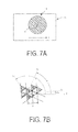
- FIGS. 2A and 2B illustrate a light beam splitter 14 .
- FIGS. 3A and 3B illustrate the function of a half-wave plate 19 of a light beam selector 18 .
- FIGS. 4A to 4C illustrate the function of a beam selection member 20 of the light beam selector 18 .
- FIG. 5 illustrates the function of the light beam selector 18 .
- FIG. 6 illustrates a rotation mechanism 18 A of the light beam selector 18 .
- FIGS. 7A and 7B illustrate the operation of a translation mechanism 15 of the light beam splitter 14 .
- FIG. 8 illustrates a beam selection member 20 ′ for a three-dimensional structured illumination microscopy (3D-SIM) mode.
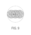
- FIG. 9 is a diagram explaining the demodulation processing of a conventional two-dimensional structured illumination microscopy (2D-SIM) mode.
- FIG. 10 is a distribution of the reciprocal of the condition number of the matrix M used in a conventional 2D-SIM.
- FIG. 11 is a diagram explaining the demodulation processing of Section 1.3.
- FIG. 13 illustrates a restorable range in a case where the number of directions of interference fringes in Section 1.3 is set to three.
- FIG. 14A illustrates a restorable region at the first step of Section 1.4 and FIG. 14B illustrates a restorable region at the second step of Section 1.4.
- FIG. 15A illustrates a restorable region at the third step of Section 1.4 and FIG. 15B illustrates a restorable region at the fourth step of Section 1.4.
- FIG. 16A is an explanatory drawing of Formula 1.27 of Section 1.4 and FIG. 16B is an explanatory drawing of a modified version of Formula 1.27.
- FIG. 17 illustrates the demodulated region according to a first example of Section 1.5.
- FIG. 18 illustrates the restored region according to a second example of Section 1.5.
- FIGS. 19A and B are explanatory drawings of Formula 1.33 in Section 1.6.
- FIG. 20 illustrates the region to be restored in Section 1.6.
- FIGS. 21A to 21D are drawings explaining in detail Formula 1.33 of Section 1.6.
- FIGS. 22A and 22B are explanatory drawings of Formula 1.63 in Section 1.9.
- FIG. 23 is a drawing illustrating the relationship between the grating pattern of three-direction interference fringes and reference vectors a 1 and a 2 of the grating.
- FIG. 24 is a drawing illustrating the interference fringe intensity distribution relationships between four modulated images.
- FIGS. 25A and 25B are drawings explaining a projection method of the three-direction interference fringes.
- FIG. 26 is a drawing explaining another projection method of the three-direction interference fringes.
- FIGS. 27A and 27B are drawings illustrating the frequency range of a demodulated image in conventional 3D-SIM.
- FIG. 27A is an xy cross-section and
- FIG. 28B is a zx cross-section.
- FIGS. 28A and 28B are drawings illustrating the frequency range of a demodulated image in Section 2.4.
- FIG. 28A is an xy cross-section and
- FIG. 28B is a zx cross-section.
- the configuration of the structured illumination microscope device will be described.
- the following description includes explanation of cases where the structured illumination microscope device is used as a total internal reflection fluorescence microscope (TIRFM).
- FIG. 1 illustrates the configuration of a structured illumination microscope device 1 .
- the structured illumination microscope device 1 includes a laser unit 100 , an optical fiber 11 , an illumination optical system 10 , an imaging optical system 30 , an image sensor 42 , a control device 43 , an image storage/processing device 44 , and an image display device 45 .
- the illumination optical system 10 is an epi-illumination optical system and illuminates a sample 2 using an objective lens 31 and a dichroic mirror 33 of the imaging optical system 30 .
- the laser unit 100 includes a first laser light source 101 , a second laser light source 102 , shutters 103 and 104 , a mirror 105 , a dichroic mirror 106 , and a lens 107 .
- the first laser light source 101 and the second laser light source 102 are both light sources that emit highly coherent laser light and emit different wavelengths of light.
- the wavelength ⁇ 1 of the first laser light source 101 is greater than the wavelength ⁇ 2 of the second laser light source 102 (that is, ⁇ 1 > ⁇ 2 ).
- the first laser light source 101 , the second laser light source 102 , and the shutters 103 and 104 are driven and controlled by the control device 43 .
- the optical fiber 11 is a polarization-maintaining single-mode fiber, for example, and guides laser light emitted from the laser unit 100 .
- the position of the output end of the optical fiber 11 can be adjusted in the optical axis O direction by a position adjusting mechanism 11 A.
- the position adjusting mechanism 11 A is driven and controlled by the control device 43 .
- the position adjusting mechanism 11 A may be a piezo element or the like, for example.
- the illumination optical system 10 includes, in order from the output end of the optical fiber 11 , a collector lens 12 , a polarizing plate 13 , a light beam splitter 14 , a condenser lens 17 , a light beam selector 18 , a lens 21 , a field diaphragm 22 , a field lens 23 , an excitation filter 24 , the dichroic mirror 33 , and the objective lens 31 .
- the polarization plane of the laser light is maintained while traveling through the optical fiber 11 , and therefore a polarizing plate 13 is not strictly required.
- including the polarizing plate 13 is effective in maintaining the quality of the polarized light in the laser light.
- the polarizing plate 13 is always necessary.
- the light beam splitter 14 includes a translation mechanism 15 and a diffractive optical element (a diffraction grating) 16 .
- the light beam selector 18 includes a half-wave plate 19 , a beam selection member 20 , and a rotation mechanism 18 A. The light beam splitter 14 and the light beam selector 18 are driven and controlled by the control device 43 .
- the imaging optical system 30 includes, in order from the sample 2 , the objective lens 31 , the dichroic mirror 33 , a barrier filter 34 , and a second objective lens 35 .
- the sample 2 is fluorescent cells (that is, cells stained using a fluorescent dye) arranged on the surface of a parallel plate glass or fluorescent living cells (that is, moving cells stained using a fluorescent dye) grown in a petri dish, for example.
- fluorescent cells that is, cells stained using a fluorescent dye
- a parallel plate glass or fluorescent living cells (that is, moving cells stained using a fluorescent dye) grown in a petri dish, for example.
- Each of these cells has both a first fluorescent region that is excited by the light of wavelength ⁇ 1 and a second fluorescent region that is excited by the light of wavelength ⁇ 2 .
- the objective lens 31 is configured as a liquid immersion (such as an oil immersion) objective lens.
- an immersion liquid (oil), not illustrated in the drawings, is filled into the gap between the objective lens 31 and the glass on which the sample 2 is arranged.
- the image sensor 42 is a two-dimensional image sensor such as a CCD or a CMOS sensor.
- the image sensor 42 is driven by the control device 43 and captures the image formed on the imaging surface 41 in order to generate an image. This image is then sent to the control device 43 and stored in the image storage/processing device 44 .
- the frame period of the image sensor 42 (that is, the period at which imaging is repeated) is determined by the limiting factor among factors such as the imaging time of the image sensor 42 (that is, the time needed to store electric charges and read out those electric charges), the time needed to switch the direction of the interference fringes, and other required times.
- the control device 43 controls the laser unit 100 , the position adjusting mechanism 11 A, the light beam splitter 14 , the light beam selector 18 , and the image sensor 42 .
- the image storage/processing device 44 processes the image sent via the control device 43 , stores the processed image in an internal memory device (not illustrated in the drawings), and outputs the processed image to the image display device 45 .
- the laser light of wavelength ⁇ 1 (first laser light) emitted from the first laser light source 101 travels past the shutter 103 to the mirror 105 , reflects off of the mirror 105 , and continues to the dichroic mirror 106 .
- the laser light of wavelength ⁇ 2 (second laser light) emitted from the second laser light source 102 travels past the shutter 104 to the dichroic mirror 106 and is combined with the first laser light.
- the first laser light and the second laser light emitted from the dichroic mirror 106 pass through the lens 107 and enter the input end of the optical fiber 11 .
- the control device 43 controls the laser unit 100 to switch the wavelength of the laser light that enters the input end of the optical fiber 11 (that is, the used wavelength ⁇ ) between the longer wavelength ⁇ 1 and the shorter wavelength ⁇ 2 .
- the laser light that enters the input end of the optical fiber 11 propagates through the optical fiber 11 and creates a point light source at the output end of the optical fiber 11 .
- the laser light emitted from that point light source is converted to a parallel beam by the collector lens 12 and then travels through the polarizing plate 13 to the diffraction grating 16 of the light beam splitter 14 , where the laser light is split into diffracted beams of various orders.
- These diffracted beams of various orders (hereinafter, referred to as “diffracted beam group” as needed) are focused by the condenser lens 17 on different positions on a pupil conjugate plane 25 .
- the pupil conjugate plane 25 has a position conjugate to the pupil 32 of the objective lens 31 (the positions at which the ⁇ first-order diffracted light is focused) via the lens 23 and the lens 21 .
- the condenser lens 17 is arranged such that the focal point of the condenser lens 17 (the focal point on the downstream side) falls on the pupil conjugate plane 25 .
- These conjugate positions are determined according to factors such as the aberration and vignetting of the objective lens 17 , and the lenses 21 and 23 that must be considered by one of ordinary skill in the art during design.
- the laser light emitted from the optical fiber 11 is typically linearly polarized light, and therefore the polarizing plate 13 can be removed.
- including the polarizing plate 13 is effective in reliably cutting out unneeded polarization components.
- the diffracted beams of each order traveling toward the pupil conjugate plane 25 enter the light beam selector 18 arranged near the pupil conjugate plane 25 .
- the light beam selector 18 selectively transmits only one pair of diffracted beams (here, the ⁇ first-order diffracted beams) among the diffracted beams of each order incident on the light beam selector 18 .
- the ⁇ first-order diffracted beams that pass through the light beam selector 18 are concentrated by the lens 21 on a plane near the field diaphragm 22 that is conjugate to the diffraction grating 16 . Then, the ⁇ first-order diffracted beams are converted to focused light by the field lens 23 , pass through the excitation filter 24 , reflect off of the dichroic mirror 33 , and are focused at different positions on the pupil plane 32 of the objective lens 31 .
- the ⁇ first-order diffracted beams that are concentrated on the pupil plane 32 are emitted from the end of the objective lens 31 as parallel beams and superposed on one another on the surface of the sample 2 , forming interference fringes. These interference fringes are used as structured illumination light.
- the focused light spots formed by the ⁇ first-order diffracted beams on the pupil plane 32 must be positioned in a prescribed circular band-shaped region positioned on the outermost periphery of the pupil plane 32 .
- the interference fringes create an evanescent field near the surface of the sample 2 .
- the difference between the periodic structure of the structured illumination light and the periodic structure of the sample 2 (that is, the periodic structure of the fluorescent regions) produces moire fringes.
- the high frequency structures of the sample 2 are shifted to frequencies lower than the original frequencies, and the light (fluorescent light) produced by these structures returns toward the objective lens 31 at angles smaller than the original angles.
- the fluorescent light produced by the sample 2 enters the objective lens 31 and is converted to parallel light by the objective lens 31 .
- This light then proceeds through the dichroic mirror 33 , the barrier filter 34 , and the second objective lens 35 and forms a modulated image of the sample 2 on the imaging surface 41 of the image sensor 42 .
- This modulated image is translated into image data by the image sensor 42 and then sent to the control device 43 and stored in the image storage/processing device 44 . Furthermore, the image storage/processing device 44 applies demodulation processing (described in more detail later) to the modulated images stored therein to generate a demodulated image (a super-resolution image). Furthermore, this super-resolution image is stored in the internal memory device (not illustrated in the drawings) of the image storage/processing device 44 and then sent to the image display device 45 .
- FIGS. 2A and 2B illustrate the light beam splitter 14 .
- FIG. 2A illustrates the diffraction grating 16 of the light beam splitter 14 as viewed from the optical axis O direction
- FIG. 2B illustrates the positional relationship of the focused light spots formed on the pupil conjugate plane by the ⁇ first-order diffracted beams. Note that FIG. 2A is only a schematic drawing, and the actual periodic structure of the diffraction grating 16 is not limited to the periodic structure illustrated in FIG. 2A .
- the diffraction grating 16 is a two-dimensional diffraction grating with a periodic structure that extends in a plurality of different directions perpendicular to the optical axis O of the illumination optical system 10 .
- the diffraction grating 16 has a periodic structure that extends in a first direction V 1 , a second direction V 2 , and a third direction V 3 which are offset by 120° from each other. It is assumed that the period (pitch) of the periodic structure of the diffraction grating 16 is the same in all three directions.
- the periodic structure of the diffraction grating 16 may be a concentration-type periodic structure formed by taking advantage of concentration (transmittance) or a phase difference-type periodic structure formed by taking advantage of level differences (phase differences). However, it is preferable that the periodic structure be a phase difference-type periodic structure because this type of periodic structure exhibits higher diffraction efficiency of the ⁇ first-order diffracted light.
- the parallel beam that enters the diffraction grating 16 is converted into a first diffracted beam group split in the first direction V 1 , a second diffracted beam group split in the second direction V 2 , and a third diffracted beam group split in the third direction V 3 .
- the first diffracted beam group contains a zero-order diffracted beam and ⁇ first-order diffracted beams.
- the diffracted beams of the same order that is, the ⁇ first-order diffracted beams
- the second diffracted beam group contains a zero-order diffracted beam and ⁇ first-order diffracted beams.
- the diffracted beams of the same order that is, the ⁇ first-order diffracted beams
- the third diffracted beam group contains a zero-order diffracted beam and ⁇ first-order diffracted beams.
- the diffracted beams of the same order that is, the ⁇ first-order diffracted beams
- the ⁇ first-order diffracted beams of the first diffracted beam group, the ⁇ first-order diffracted beams of the second diffracted beam group, and the ⁇ first-order diffracted beams of the third diffracted beam group are focused at different positions on the pupil conjugate plane by the condenser lens 17 .
- the focused light spots 25 d and 25 g formed by the ⁇ first-order diffracted beams of the first diffracted beam group are symmetric about the optical axis O, and the direction in which the focused light spots 25 d and 25 g are arranged corresponds to the first direction V 1 .
- the focused light spots 25 c and 25 f formed by the ⁇ first-order diffracted beams of the second diffracted beam group are symmetric about the optical axis O, and the direction in which the focused light spots 25 c and 25 f are arranged corresponds to the second direction V 2 .
- the distance from the focused light spots 25 c and 25 f of the second diffracted beam group to the optical axis O is the same as the distance from the focused light spots 25 d and 25 g of the first diffracted beam group to the optical axis O.
- the focused light spots 25 b and 25 e formed by the ⁇ first-order diffracted beams of the third diffracted beam group are symmetric about the optical axis O, and the direction in which the focused light spots 25 b and 25 e are arranged corresponds to the third direction V 3 .
- the distance from the focused light spots 25 b and 25 e of the third beam group to the optical axis O is the same as the distance from the focused light spots 25 d and 25 g of the first diffracted beam group to the optical axis O.
- the distance D from the optical axis O to the focused light spots 25 b to 25 g is given by the following formula, where X is the wavelength of the laser light emitted from the optical fiber 11 , P is the pitch of the periodic structure of the diffraction grating 16 , and fc is the focal length of the lens 17 . D ⁇ 2 fc ⁇ /P
- focused light spots refers to the weighted center positions of regions that have an intensity of at least 80% of the maximum intensity. Therefore, in the illumination optical system 10 of the present embodiment, the light beams do not necessarily have to be focused to the point of forming perfect focused light spots.
- the translation mechanism 15 is a piezo motor or the like.
- the translation mechanism 15 moves the diffraction grating 16 in a direction that is orthogonal to the optical axis O of the illumination optical system 10 but not orthogonal to the first direction V 1 , the second direction V 2 , and the third direction V 3 . Moving the diffraction grating 16 in this direction shifts the phase of the fringes of the structured illumination light (this will be described in more detail later).
- FIGS. 3A to 4C illustrate the light beam selector 18 .
- the half-wave plate 19 of the light beam selector 18 sets the polarization direction of the diffracted beams of each order incident thereon.
- the beam selection member 20 of the light beam selector 18 is a mask that selectively transmits just the ⁇ first-order diffracted beams of one group among the first to third diffracted beam groups.
- the rotation mechanism (not illustrated in the drawings) of the light beam selector 18 rotates the beam selection member 20 about the optical axis O in order to switch ⁇ first-order diffracted beams to be selected of the first to third diffracted beam groups.
- the rotation mechanism also rotates the half-wave plate 19 about the optical axis O in unison with the beam selection member 20 in order to keep the selected ⁇ first-order diffracted beams that are incident on the sample 2 s-polarized.
- the light beam selector 18 switches the direction of the structured illumination light fringes while maintaining the state of those structured illumination light fringes.
- the conditions for maintaining the state of the fringes will be described in more detail.
- the fast axis of the half-wave plate 19 must be oriented such that the polarization direction of ⁇ first-order diffracted beams to be selected is orthogonal to the direction in which the ⁇ first-order diffracted beams are split (one of the first direction V 1 to third direction V 3 ).
- the “fast axis” of the half-wave plate 19 refers to the axis in the direction in which the phase delay of light polarized in that direction is minimized when that polarized light passes through the half-wave plate 19 .
- An opening pattern formed in the beam selection member 20 includes a first opening 20 A and a second opening 20 B that each allow one of the ⁇ first-order diffracted beams of the same diffracted beam group to pass through.
- the lengths of the first opening 20 A and the second opening 20 B around the optical axis O are set to lengths that allow diffracted beams that are linearly polarized in the abovementioned direction to pass through. Therefore, the first opening 20 A and the second opening 20 B both have a partial ring shape.
- the rotation position of the half-wave plate 19 illustrated in FIG. 3A in which the fast axis of the half-wave plate 19 is parallel to the axis of the polarizing plate 13 , serves as a reference rotation position for the half-wave plate 19 (hereinafter, a “first reference position”).
- the rotation position of the beam selection member 20 in which the beam selection direction of the beam selection member 20 (that is, the direction in which ⁇ first-order diffracted beams to be selected are split) is orthogonal to the axis of the polarizing plate 13 serves as a reference rotation position for the beam selection member 20 (hereinafter, a “second reference position”).
- the rotation of the half-wave plate 19 and the beam selection member 20 should be controlled such that the amount by which the half-wave plate 19 is rotated from the first reference position is equal to half of the amount by which the beam selection member 20 is rotated from the second reference position.
- the beam selection member 20 is rotated by ⁇ from the second reference position.
- the rotation mechanism 18 A of the light beam selector 18 rotates the beam selection member 20 clockwise such that the beam selection direction thereof is rotated by an angle of ⁇ 1 from the second reference position and also rotates the half-wave plate 19 clockwise such that the fast axis thereof is rotated by an angle of ⁇ 1 /2 from the first reference position.
- the polarization direction of the diffracted beams of each order before passing through the half-wave plate 19 are parallel to the axis of the polarizing plate 13 .
- the polarization direction of the diffracted beams of each order after passing through the half-wave plate 19 is rotated clockwise by an angle of ⁇ 1 , and therefore the polarization direction of the selected ⁇ first-order diffracted beams is orthogonal to the direction in which those ⁇ first-order diffracted beams are split (the first direction V 1 ).
- the rotation mechanism 18 A of the light beam selector 18 rotates the beam selection member 20 clockwise such that the beam selection direction thereof is rotated by an angle of ⁇ 2 from the second reference position and also rotates the half-wave plate 19 clockwise such that the fast axis thereof is rotated by an angle of ⁇ 2 /2 from the first reference position.
- the polarization direction of the diffracted beams of each order before passing through the half-wave plate 19 are parallel to the axis of the polarizing plate 13 .
- the polarization direction of the diffracted beams of each order after passing through the half-wave plate 19 is rotated clockwise by an angle of ⁇ 2 , and therefore the polarization direction of the selected ⁇ first-order diffracted beams is orthogonal to the direction in which those ⁇ first-order diffracted beams are split (the second direction V 2 ).
- the rotation mechanism 18 A of the light beam selector 18 rotates the beam selection member 20 counter-clockwise (as viewed from the sample side—the same applies below) such that the beam selection direction thereof is rotated by an angle of ⁇ 3 from the second reference position and also rotates the half-wave plate 19 counter-clockwise such that the fast axis thereof is rotated by an angle of ⁇ 3 /2 from the first reference position.
- the polarization direction of the diffracted beams of each order before passing through the half-wave plate 19 are parallel to the axis of the polarizing plate 13 .
- the polarization direction of the diffracted beams of each order after passing through the half-wave plate 19 is rotated counter-clockwise by an angle of ⁇ 3 , and therefore the polarization direction of the selected ⁇ first-order diffracted beams is orthogonal to the direction in which those ⁇ first-order diffracted beams are split (the third direction V 3 ).
- the direction of the fast axis of the half-wave plate 19 is set according to the direction in which the ⁇ first-order diffracted beams selected by the beam selection member 20 are split such that the fast axis of the half-wave plate 19 bisects the angle between the polarization direction of the ⁇ first-order diffracted beams incident on the half-wave plate 19 (that is, the direction of the axis of the polarizing plate 13 ) and the polarization direction that the ⁇ first-order diffracted beams should have after exiting from the half-wave plate 19 (that is, the direction orthogonal to the split direction).
- the rotation mechanism 18 A of the light beam selector 18 should rotate the half-wave plate 19 and the beam selection member 20 at a gear ratio of 2:1.
- the rotation mechanism 18 A includes, for example, a support member (not illustrated in the drawings) that supports the beam selection member 20 and allows the beam selection member 20 to rotate about the optical axis O, a first gear (not illustrated in the drawings) formed surrounding the support member, a second gear (not illustrated in the drawings) that meshes with the first gear, and a motor (a rotation motor—not illustrated in the drawings) that is connected to the second gear. Activating this motor rotates the second gear, and this rotary force is transmitted to the first gear, thereby rotating the beam selection member 20 about the optical axis O.
- FIG. 5 illustrates the function of the light beam selector 18 as described above.
- the arrows surrounded by circles indicate the polarization direction of the light beams
- the arrows surrounded by squares indicate the direction in which the axis of an optical element is oriented.
- the rotatable half-wave plate 19 is used to keep the ⁇ first-order diffracted beams incident on the sample 2 s-polarized.
- the rotatable half-wave plate 19 may be replaced by a fixed liquid crystal element that is used to achieve the same effect as the half-wave plate 19 .
- Electronically controlling the orientation of the liquid crystal molecules in the liquid crystal element makes it possible to control the anisotropicity of the refractive index of the liquid crystal element, thereby making it possible to effectively rotate the fast axis of the half-wave plate about the optical axis O.
- a plurality of slits 20 C are formed in the periphery of the beam selection member 20 , and the rotation mechanism 18 A includes a timing sensor 20 D for detecting the slits 20 C. This makes it possible for the rotation mechanism 18 A to detect not only the rotation angle of the light beam selector 18 but also the rotation angle of the half-wave plate 19 .
- FIGS. 7A and 7B illustrate the operation of the translation mechanism 15 of the light beam splitter 14 .
- the demodulation processing In order to be able to apply the demodulation processing (described in more detail later), at least two modulated images of the same sample 2 in which the directions of the interference fringes are the same but the phases thereof are different are required. This is because the modulated image of the structure of the sample 2 that is generated by the structured illumination microscope device 1 contains a zero-order modulation component, a +first-order modulation component, and a ⁇ first-order modulation component, which represent structural information in which the spatial frequency is modulated due to the structured illumination light. It is necessary to make these superposed three unknown parameters known during the demodulation processing (described in more detail later).
- the translation mechanism 15 of the light beam splitter 14 shifts the diffraction grating 16 in a direction (the x direction) that is orthogonal to the optical axis O of the illumination optical system 10 but not orthogonal to any of the first direction V 1 , the second direction V 2 , or the third direction V 3 in order to shift the phase of the interference fringes.
- the distance L by which the diffraction grating 16 must be shifted in order to shift the phase of the interference fringes by a desired amount ⁇ is not necessarily the same when the beam selection direction of the light beam selector 18 is the first direction V 1 , when the beam selection direction is the second direction V 2 , and when the beam selection direction is the third direction V 3 .
- ⁇ 1 be the angle between the direction in which the diffraction grating 16 is shifted (the x direction) and the first direction V 1
- ⁇ 2 be the angle between the direction in which the diffraction grating 16 is shifted (the x direction) and the second direction V 2
- ⁇ 3 be the angle between the direction in which the diffraction grating 16 is shifted (the x direction) and the third direction V 3 .
- the distance L by which the diffraction grating 16 must be shifted in the x direction to achieve a desired phase shift ⁇ of the interference fringes depends on the angle ⁇ between the beam selection direction (the first direction V 1 , the second direction V 2 , or the third direction V 3 ) and the x direction, as given below by equation 1.
- L ⁇ P /( a ⁇ 4 ⁇
- the distance L by which the diffraction grating 16 must be shifted in the x direction to achieve a phase shift ⁇ of 2 ⁇ of the interference fringes is P/(a ⁇ 2 ⁇
- M is the number of directions of the periodic structure held by the diffraction grating 16 .
- the image storage/processing device 44 described above is constituted by a computer for performing computations by executing a computation program, a computation circuit for performing computation processing, or a combination of both.
- the computer may be a general purpose computer in which a computation program is installed via storage media or a communications network.
- the basic procedures for demodulation processing by the image storage/processing device 44 will be described below.
- the basic procedures include the following four steps.
- Step 1 Fourier-transform each of a plurality of modulated images and generate a plurality of spatial frequency spectra.
- Step 2 In the Fourier space, isolate the zero-order modulation component of the fluorescence light, the +first-order modulation component of the fluorescence light, and the ⁇ first-order modulation component of the fluorescence light, which are superposed in each of the spatial frequency spectra.
- Step 3 In the Fourier space, rearrange the isolated zero-order modulation component of the fluorescence light, the +first-order modulation component of the fluorescence light, and the ⁇ first-order modulation component of the fluorescence light, thereby generating the spatial frequency spectrum of the demodulated image.
- Step 4 Inverse Fourier-transform the spatial frequency spectrum of the demodulated image, thereby acquiring the demodulated image (i.e. super-resolution image).
- the interference fringes projected onto the sample 2 are stipulated as two-beam interference fringes (that is, an example has been given where the structured illumination microscope device 1 is used in 2D-SIM mode), but three-beam interference fringes may also be used as the interference fringes projected onto the sample 2 (that is, the structured illumination microscope device 1 may be used in 3D-SIM mode).
- the beam selection member 20 ′ illustrated in FIG. 8 is used in place of the beam selection member 20 illustrated in FIG. 6 .
- this beam selection member 20 ′ an additional opening 20 E is formed in the beam selection member 20 illustrated in FIG. 6 in order to allow the zero-order diffracted beam to pass through.
- This opening 20 E is formed near the optical axis O and is circular, for example.
- the interference fringes are produced by interference of three types of diffracted beams (three-beam interference) and spatially modulate the sample 2 not only in the surface direction but also in the depth direction of the sample 2 . Therefore, these interference fringes can be used to produce a super-resolution image of the sample 2 in the depth direction thereof as well.
- content of the demodulation processing to be executed by the image storage/processing device 44 differs between the 2D-SIM mode and the 3D-DIM mode. This is because in modulated images generated through 2D-SIM, three components, namely the zero-order modulation component of the fluorescence light, the +first-order modulation component of the fluorescence light, and the ⁇ first-order modulation component of the fluorescence light are superposed, but in modulated images generated through 3D-SIM, five components are superposed, namely the zero-order modulation component of the fluorescence light, the +first-order modulation component of the fluorescence light, the ⁇ first-order modulation component of the fluorescence light, the +second-order modulation component of the fluorescence light, and the ⁇ second-order modulation component of the fluorescence light.
- the number of frames that the control device 43 must acquire and the like differ because the number of superposed modulation components in modulated images differs between 2D-SIM mode and 3D-SIM mode. Next, the details of this configuration will be described.
- the diffraction grating is shifted in order to shift the phase of the interference fringes, but instead of shifting the diffraction grating, the difference in optical path length between the ⁇ first-order diffracted beams may be changed.
- a phase plate may be inserted or removed from the optical path of the +first-order diffracted beam and/or the optical path of the ⁇ first-order diffracted beam.
- phase plate thickness of the phase plate and the amount of phase shift differs depending on the used wavelength
- a plurality of phase plates having differing thicknesses may be mounted on a turret and be selectively inserted into the optical path in accordance with the used wavelength.
- the polarization direction may be set to any direction and may be changed during image capturing.
- the number of light source wavelengths is set to one, but may be expanded to two or more.
- the half-wave plate that can be rotated about the optical axis O is used to keep the ⁇ first-order diffracted beams incident on the sample 2 s-polarized.
- a fixed quarter-wave plate and a quarter-wave plate that can be rotated about the optical axis O may also be used. In this case, however, the rotation angle of the quarter-wave plate relative to the first reference position must be set to the same value as the rotation angle of the beam selection member relative to the second reference position.
- a combination of ⁇ first-order diffracted light and zero-order diffracted light is used as the diffracted light for forming the interference fringes (two-beam interference fringes in 2D-SIM mode or three-beam interference fringes in 3D-SIM mode), but other combinations may also be used.
- the interference fringes two-beam interference fringes in 2D-SIM mode or three-beam interference fringes in 3D-SIM mode
- any three types of diffracted light in which there are equal intervals between the diffraction orders may be used.
- combinations such as zero-order diffracted light, first-order diffracted light, and second-order diffracted light; ⁇ second-order diffracted light and zero-order diffracted light; and ⁇ third-order diffracted light and zero-order diffracted light may all be used, for example.
- the illumination optical system 10 of the device described above is an epi-illumination optical system that uses the objective lens 31 .
- the illumination optical system is not limited to this example and may be a transmission/reflection illumination optical system that uses a condenser lens in place of the objective lens 31 .
- the focused light spots are formed on the pupil plane of the condenser lens.
- interference fringe intensity distribution in 2D-SIM mode is defined as follows.
- an image captured by the objective lens according to the fluorescence light intensity distribution I fl (x), that is, the modulated image I(x), is expressed by the following incoherent image forming formula.
- I ( x ) ⁇ dx′dy′PSF ( x ⁇ x ′) I fl ( x ′) (1.2)
- ⁇ ( ⁇ ) OTF ( ⁇ ) ⁇ fl ( ⁇ ) (1.3)
- OTF ( ⁇ ) [ PSF ( x )]
- interference fringe intensity distribution in 2D-SIM is expressed as follows (the fringes have a sinusoidal intensity distribution).
- ⁇ 0 is the spatial frequency of the interference fringes (modulation frequency).
- K ⁇ ⁇ ( ⁇ ) ⁇ ⁇ ( ⁇ ) + ⁇ ⁇ ( ⁇ - ⁇ 0 ) ⁇ e - i ⁇ ⁇ ⁇ + ⁇ ⁇ ( ⁇ - ⁇ 0 ) ⁇ e i ⁇ ⁇ ⁇ 2 ( 1.6 )
- ⁇ indicates coordinates in Fourier space.
- the spatial frequency spectrum in Fourier space is referred to simply as “spectrum”. Additionally, when the phase of the interference fringes is ⁇ i , the acquired modulated image will be correspondingly marked with the subscript “ ⁇ i ”.
- the three components namely the ⁇ first-order modulation component of the fluorescence light, the +first-order modulation component of the fluorescence light, and the zero-order modulation component of the fluorescence light, are superposed at the observation pointy in the spectrum of the modulated image acquired through 2D-SIM.
- the three terms on the right side of Formula 1.7 correspond to these three components.
- the spectrum of the modulated image can be expressed by the three modulation components of the fluorescence light (i.e. the zero-order modulation component and the ⁇ first-order modulation components).
- the +first-order modulation component superposed at the observation point ⁇ is a value (restoration value) that a restoration point ( ⁇ ) in the spectrum of the demodulated image must have;
- the ⁇ first-order modulation component superposed at the observation point ⁇ is a value (restoration value) that a restoration point ( ⁇ + ⁇ 0 ) in the spectrum of the demodulated image must have;
- the zero-order modulation component superposed at the observation point ⁇ is a value (restoration value) that a restoration point ⁇ in the spectrum of the demodulated image must have.
- the large black spot in FIG. 9 corresponds to an observation point and the two small black spots on either side of the large black spot and the large black spot itself correspond to the three restoration points restored from the observation point.
- ⁇ ⁇ 1 ( ⁇ ) OTF ( ⁇ )(1 ⁇ 2 e ⁇ i ⁇ 1 ⁇ o ( ⁇ 0 )+ ⁇ o ( ⁇ )+1 ⁇ 2 e i ⁇ 1 ⁇ o ( ⁇ + ⁇ 0 )) (1.8)
- ⁇ ⁇ 2 ( ⁇ ) OTF ( ⁇ )(1 ⁇ 2 e ⁇ i ⁇ 2 ⁇ o ( ⁇ 0 )+ ⁇ o ( ⁇ )+1 ⁇ 2 e i ⁇ 2 ⁇ o ( ⁇ + ⁇ 0 )) (1.9)
- ⁇ ⁇ 3 ( ⁇ ) OTF ( ⁇ )(1 ⁇ 2 e ⁇ i ⁇ 3 ⁇ o ( ⁇ 0 )+ ⁇ o ( ⁇ )+1 ⁇ 2 e i ⁇ 3 ⁇ o ( ⁇ + ⁇ 0 )) (1.10)
- the restoration values (right side) of the three restoration points corresponding to an observation point in the spectra of the three modulated images can be calculated from the three observation values (left side) of the observation point.
- the spatial frequency (modulation frequency) of the fringes in conventional 2D-SIM is set such that the relationship
- the restoration value outside the normal resolution region i.e. the super-resolution region
- a super-resolution image can be obtained as the demodulated image.
- FIG. 10 is the result of plotting the condition number of the matrix M with the phase ⁇ i as a parameter.
- FIG. 10 is a distribution of the reciprocal of the condition number of the matrix M.
- the phase ⁇ 1 of the first modulated image is set to 0°
- the phase ⁇ 2 of the second modulated image and the phase ⁇ 3 of the third modulated image are set as variables.
- the horizontal axis is ⁇ 2 and the vertical axis is ⁇ 3 .
- the ⁇ first-order modulation component of the fluorescence light superposed at the observation point ⁇ and the zero-order modulation component of the fluorescence light superposed at the observation point ( ⁇ + ⁇ 0 ) both correspond to the restoration value of the restoration point ( ⁇ + ⁇ 0 ); and the +first-order modulation component of the fluorescence light superposed at the observation point ( ⁇ + ⁇ 0 ) and the zero-order modulation component of the fluorescence light superposed at the observation point ⁇ both correspond to the restoration value of the restoration point ⁇ . That is, common restoration values of the two restoration points ⁇ and ( ⁇ + ⁇ 0 ) are included in these two restoration points and ( ⁇ + ⁇ 0 ). This relationship will be used in the two-image two-point restoration discussed in this section. Hereinafter, a detailed description will be given.
- the interference fringe intensity distribution is assumed to be the same as in conventional 2D-SIM, the observation range of the spectrum of the modulated image is expressed as
- the spatial frequency (modulation frequency) ⁇ 0 of the fringes in this section is set such that
- the observation values of the two observation points ⁇ and ( ⁇ + ⁇ 0 ), separated from each other by ⁇ 0 can be obtained from the spectrum of a single modulated image.
- the observation value of ( ⁇ + ⁇ 0 ) can only be obtained when ⁇ is within a range where ( ⁇ + ⁇ 0 ) ⁇ 2NA is satisfied.
- ⁇ ⁇ ( ⁇ ) OTF ( ⁇ )(1 ⁇ 2 e ⁇ i ⁇ ⁇ o ( ⁇ 0 )+ ⁇ o ( ⁇ )+ ⁇ o ( ⁇ )+1 ⁇ 2 e i ⁇ ⁇ o ( ⁇ + ⁇ 0 )) (1.12)
- ⁇ ⁇ ( ⁇ + ⁇ 0 ) OTF ( ⁇ + ⁇ 0 )(1 ⁇ 2 e ⁇ i ⁇ ⁇ o ( ⁇ )+ ⁇ o ( ⁇ + ⁇ 0 )+1 ⁇ 2 e i ⁇ ⁇ o ( ⁇ +2 ⁇ 0 )) (1.13)
- Restoration values of four restoration points appear on the right side of Formulas 1.12 and 1.13. Two more formulas are needed to discover these four restoration values.
- ⁇ 1 is substituted for OTF( ⁇ )
- T 2 is substituted for OTF( ⁇ + ⁇ 0 )
- ⁇ 1 represents the phase ⁇ of the first modulated image
- ⁇ 2 represents the phase ⁇ of the second modulated image.
- the inner ring of the two rings shown is the outer edge (
- 2NA) of the normal resolution range.
- the outer ring is the outer edge (
- 4NA) of the super-resolution range.
- the two large black spots in FIG. 11 represent two observation points separated from each other by the spatial frequency (modulation frequency) ⁇ 0 of the fringes; and the two large black spots and the two small black spots represent the four restoration points restored from the two observation points.
- restoration values of at least a portion of the normal resolution range and restoration values of at least a portion of the super-resolution range can be found.
- the determinant of the matrix M must be a value other than zero.
- the determinant of the matrix M is expressed as follows:
- I ⁇ ⁇ 1 ⁇ ( ⁇ ) ⁇ 1 2 ⁇ ( I ⁇ o ⁇ ( ⁇ - ⁇ 0 ) + 2 ⁇ I ⁇ o ⁇ ( ⁇ ) + I ⁇ o ⁇ ( ⁇ + ⁇ 0 ) ) ( 1.21 )
- I ⁇ ⁇ 2 ⁇ ( ⁇ ) ⁇ 1 2 ⁇ ( - I ⁇ o ⁇ ( ⁇ - ⁇ 0 ) + 2 ⁇ I ⁇ o ⁇ ( ⁇ ) - I ⁇ o ⁇ ( ⁇ + ⁇ 0 ) ) ( 1.22 )
- I ⁇ o ⁇ ( ⁇ ) 1 2 ⁇ ⁇ 1 ⁇ ( I ⁇ ⁇ 1 ⁇ ( ⁇ ) + I ⁇ ⁇ 2 ⁇ ( ⁇ ) ) ( 1.23 )
- the darkened regions in FIG. 12A represent the restorable range when ⁇
- 2NA).
- the inner ring of the two rings shown is the outer edge (
- 2NA) of the normal resolution range
- the outer ring is the outer edge (
- 4NA) of the super-resolution range.
- the number of directions of interference fringes is assumed to be one, but a wide region such as that illustrated in FIG. 13 can be restored by setting the number of directions of interference fringes to three and applying the demodulation processing in the same way as described in Section 1.3 to each direction.
- Two-pass restoration will be described as the 2D-SIM demodulation processing of the present embodiment.
- the number of directions of interference fringes is set to two.
- each of the interference fringes is expressed as a wave vector for the purpose of distinguishing the plurality of interference fringes with differing directions and periods (pitches).
- the magnitude of the wave vector represents the magnitude of the spatial frequency of the interference fringes
- the direction of the wave vector represents the direction of the interference fringes.
- Step 1 The wave vector is ⁇ 0 , two modulated images with differing phases are acquired, and spectra of each of the two modulated images are acquired.
- Each of the two modulated images is expressed as follows: ⁇ I ⁇ 1 (0) ,I ⁇ 2 (0) ⁇
- Step 2 The wave vector is Fi, two modulated images with differing phases are acquired, and spectra of each of the two modulated images are acquired.
- Each of the two modulated images is expressed as follows: ⁇ I ⁇ 1 (1) ,I ⁇ 2 (1) ⁇
- Step 3 On the basis of the restoration values found in the preceding steps and the following formulas, the restoration values of the regions illustrated in FIG. 15A are found.
- I ⁇ ⁇ 1 ( 1 ) ⁇ ( ⁇ ) ⁇ 1 2 ⁇ ( e - i ⁇ ⁇ ⁇ 1 ⁇ I ⁇ o ⁇ ( ⁇ - ⁇ 1 ) + 2 ⁇ I ⁇ o ⁇ ( ⁇ ) + e i ⁇ ⁇ ⁇ 1 ⁇ I ⁇ o ⁇ ( ⁇ + ⁇ 1 ) ) ( 1.24 )
- I ⁇ ⁇ 2 ( 1 ) ⁇ ( ⁇ ) ⁇ 1 2 ⁇ ( e - i ⁇ ⁇ ⁇ 2 ⁇ I ⁇ o ⁇ ( ⁇ - ⁇ 1 ) + 2 ⁇ I ⁇ o ⁇ ( ) + e i ⁇ ⁇ ⁇ 2 ⁇ I ⁇ o ⁇ ( ⁇ + ⁇ 1 ) ) ( 1.25 )
- Step 4 On the basis of the restoration value of the normal resolution range found in step 2 (the
- Steps 1 and 3 can be combined and expressed as illustrated in FIG. 16B . That is, the four black spots linked in the horizontal direction on the horizontal line in FIG. 16B express the positions in Fourier space (wave number space) of the four restoration values (unknowns) found in the same system of equations as Formula 1.14, which is solved in step 1.
- the large black spot in the center represents the position in Fourier space (wave number space) of one known number found from the Formula of step 1; and the small black spots at both ends represent the positions in Fourier space (wave number space) of two restoration values (unknowns) of the system of equations 1.26, which is solved in step 3.
- the relative positional relationships of these eight black spots is the same in every example.
- the range of possible positions in Fourier space (wave number space) of the black spots is restricted by the range of possible positions in Fourier space (wave number space) of the two large black spots (center black spots). Because the range of possible positions of the two large black spots is
- FIG. 16A illustrates steps 2 and 4 in the same manner as FIG. 16B .
- Two-pass restoration is carried out, paying particular attention to curbing the number of modulated images (the number of spectra).
- the number of directions of the wave vector is set to two, two modulated images having differing phases are acquired at each of the two differing wave vectors ⁇ 1 and ⁇ 2 (a total of four modulated images are acquired), and the spectrum of each of these four modulated images is generated (a total of four spectra are generated).
- the phase difference ⁇ between the two modulated images acquired at the same wave vector is set to ⁇ #7.
- the magnitude ⁇ i of the wave vector is set to
- two-image two-point restoration is performed instead of Two-pass restoration, paying particular attention to computation accuracy.
- the number of directions of wave vector is set to three, two modulated images having differing phases are acquired at each of the three differing wave vectors ⁇ 1 , ⁇ 2 , and ⁇ 3 (a total of six modulated images are acquired), and the spectrum of each of these six modulated images is generated (a total of six spectra are generated).
- the phase difference ⁇ between the two modulated images acquired at the same wave vector is set to ⁇ .
- is intentionally set to be less than 2NA in order to avoid the formation of gaps in the restoration region.
- of the wave vector is set to
- the number of directions of wave vectors is set to three (a modulated image is acquired at each of the three wave vectors ⁇ 1 , ⁇ 2 , and ⁇ 3 and a spectrum of each of these modulated images is generated).
- the number of phases is set to two (two modulated images I (0) and I (1) with the same fringe direction and differing phases are obtained) at one direction among the three directions (wave vector ⁇ 1 ), but at each of the other directions (wave vectors ⁇ 2 and ⁇ 3 ), the number of phases is held to one (two modulated images I (2) and I (3) with differing fringe directions are obtained).
- the magnitude of each of the wave vectors is set to
- interference fringe intensity distribution of each of the four modulated images I (0) , I (1) , I (2) , and I (3) are expressed as follows:
- FIGS. 19A and B are explanatory drawings of the calculations. Note that
- and ⁇ 1 ⁇ 2
- the three large black spots in FIG. 19A represent the three observation points positioned at the peaks of the triangle formed from the three wave vectors ⁇ 1 , ⁇ 2 , and ⁇ 3 in the spectrum of each of the modulated images; and the three large black spots and the nine small black spots represent the restoration points (total of 12 restoration points) restored from these three observation points.
- the number of modulated images (the number of spectra) is set to four, a total of 12 observation values are acquired from three observation points. Restoration values of the 12 restoration points can be individually found by simultaneously solving the 12 formulas related to these 12 observation values.
- FIG. 19B is an explanatory drawing of a case where the direction of the triangle is inverted and restoration is performed as described above. It is possible to perform the restoration illustrated in FIG. 19A and the restoration illustrated in FIG. 19B in parallel. In this section, both restorations are performed and the entire darkened region illustrated in FIG. 20 is restored.
- FIG. 20 is a drawing in which the restoration region illustrated in FIG. 19A and the restoration region illustrated in FIG. 19B are combined.
- FIG. 21A to D are explanatory drawings that break the calculation used in this section down into three steps.
- FIG. 21A illustrates the four restoration points 1 to 4 restored in step 1.
- FIG. 21B illustrates the four restoration points 5 to 8 restored in step 2.
- FIG. 21C illustrates the four restoration points 9 to 12 restored in step 3.
- FIG. 21D is a correspondence table showing the relationship between the numbers 1 to 12 in the drawings and the restoration values.
- Step 1 Restoration values of each of the restoration points 1, 2, 3, and 4 are found by applying the four observation values related to the two lined up observation points 1 and 2 at an interval
- Step 2 Using the restoration values of each of the restoration points 1 and 2, restoration values of each of the four restoration points 5, 6, 7, and 8, separated from the restoration points 1 and 2 by the amount of the wave vectors ⁇ 2 and ⁇ 3 , are found.
- Four formulas are used here, namely two formulas related to the direction of the wave vector ⁇ 1 (part for 2 phases), one formula related to the direction of the wave vector ⁇ 2 , and one formula related to the direction of the wave vector ⁇ 3 .
- Step 3 Using the restoration values of each of the restoration points 1, 2, and 5, restoration values of each of the remaining restoration points 9, 10, 11, and 12, separated from the restoration points 1, 2, and 5 by the amount of the wave vectors ⁇ 2 and ⁇ 3 , are found.
- Four formulas are used here, namely two formulas related to the direction of the wave vector (part for two observation points), and two formulas related to the direction of the wave vector ⁇ 3 (part for two observation points).
- the number of modulated images (the number of spectra of the modulated images) is set to three and the number of unmodulated images (the number of spectra of the unmodulated images) is set to one, a total of 12 observation values are acquired from three observation points.
- Restoration values of the 12 restoration points can be individually found by simultaneously solving the 12 formulas (the nine in Formula 1.7 related to the spectrum of the modulated image, and the three in Formula 1.53 related to the spectrum of the unmodulated image) related to these 12 observation values.
- the interference fringes projected on the sample are the combined sum of three interference fringes having differing directions (three-direction interference fringes). Note that the method of projecting the three-direction interference fringes is described later.
- three-direction interference fringes simultaneously comprising the three wave vectors ⁇ 1 , ⁇ 2 , and ⁇ 3 are used, four modulated images having differing phases are acquired using the three-direction interference fringes, and a spectrum of each of these four modulated images is generated.
- a total of seven components are superposed at the observation point ⁇ in the spectrum of the modulated image, namely, the zero-order modulation component of the fluorescence light, the ⁇ first-order modulation components of the fluorescence light of the wave vector ⁇ 1 , the ⁇ first-order modulation components of the fluorescence light of the wave vector ⁇ 2 , and the ⁇ first-order modulation components of the fluorescence light of the wave vector ⁇ 3 .
- the restoration values of the 12 restoration points are contained within the entirety of these three observation points ⁇ , ( ⁇ + ⁇ 1 ), and ( ⁇ + ⁇ 2 ).
- FIGS. 22A and B are explanatory drawings of the 12 restoration points. Note that
- and ⁇ 1 ⁇ 2
- the three large black spots in FIG. 22A represent the three observation points positioned at the peaks of the triangle formed from the three wave vectors ⁇ 1 , ⁇ 2 and ⁇ 3 in the spectrum of each of the modulated images; and the three large black spots and the nine small black spots represent the restoration points (total of 12 restoration points) restored from these three observation points.
- FIG. 22B is an explanatory drawing of a case where the direction of the triangle is inverted and restoration is performed as described above. It is possible to perform the restoration illustrated in FIG. 22A and the restoration illustrated in FIG. 22B in parallel. In this section, both restorations are performed and the same region as the darkened region illustrated in FIG. 20 is restored.
- the interference fringe intensity distribution in each of the four modulated images I (0) , I (2) , I (3) , and I (4) is as follows:
- K 1 ⁇ ( x ) 1 + 2 ⁇ a ⁇ ( cos ⁇ ( 2 ⁇ ⁇ ⁇ ⁇ ⁇ 1 ⁇ x ) + cos ⁇ ( 2 ⁇ ⁇ ⁇ ⁇ ⁇ 2 ⁇ x ) + cos ⁇ ( 2 ⁇ ⁇ ⁇ ⁇ ⁇ 3 ⁇ x ) ) ( 1.69 )
- K 2 ⁇ ( x ) 1 + 2 ⁇ a ⁇ ( - cos ⁇ ( 2 ⁇ ⁇ ⁇ ⁇ 1 ⁇ x ) + cos ⁇ ( 2 ⁇ ⁇ ⁇ ⁇ 2 ⁇ x ) - cos ⁇ ( 2 ⁇ ⁇ ⁇ ⁇ 3 ⁇ x ) ) ( 1.70 )
- K 3 ⁇ ( x ) 1 + 2 ⁇ a ⁇ ( cos ⁇ ( 2 ⁇ ⁇ ⁇ ⁇ 1 ⁇ x ) - cos ⁇ ( 2 ⁇ ⁇ ⁇ ⁇ ⁇ 1
- K 2 ( x ) K 1 ( x+ 1 ⁇ 2 a 1 ) (1.74)
- K 3 ( x ) K 1 ( x+ 1 ⁇ 2 a 2 ) (1.75)
- K 4 ( x ) K 1 ( x+ 1 ⁇ 2 a 1 +1 ⁇ 2 a 2 ) (1.76)
- a 1 2 ⁇ ⁇ ⁇ k 2 ⁇ k 3 k 1 ⁇ ( k 2 ⁇ k 3 ) ( 1.77 )
- a 2 2 ⁇ ⁇ ⁇ k 3 ⁇ k 1 k 2 ⁇ ( k 3 ⁇ k 1 ) ( 1.78 )
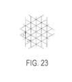
- FIG. 23 is a drawing illustrating the relationship between the grating pattern of three-direction interference fringes and reference vectors a 1 and a 2 of the grating.
- FIG. 24 is a drawing illustrating the interference fringe intensity distribution relationships between four modulated images.
- the grating pattern moves in parallel between the four modulated images so that overlapping does not occur. Additionally, the unit of the amount of movement is half the reference vector of the grating.
- the diffraction grating 16 ( FIG. 2A ) described above can be used when causing the three-direction interference fringes to occur in the structured illumination microscope device described above, just as when causing other interference fringes (single-direction interference fringes) to occur.
- the aperture pattern of the beam selection member 20 is configured to cut the zero-order diffracted light beams of each group of the three groups of diffracted light beams generated by the diffraction grating 16 , the second-order or higher-order diffracted light beams of each group, and the +first-order diffracted light beams of each group, and only transmit the ⁇ first-order diffracted light beams of each group.
- the focused light spot formed on the pupil plane will consist only of focused light spots formed by three ⁇ first-order diffracted light beams.
- FIG. 25A illustrates the arrangement of focused light spots in a case where the extra diffracted light beams are not cut by the beam selection member 20 .
- the 25B illustrates the arrangement of focused light spots in a case where the extra diffracted light beams are cut by the beam selection member 20 .
- three focused light spots offset 120° from each other are formed.
- the diffracted light beams (here, the three ⁇ first-order diffracted light beams) emitted from these three focused light spots enter the illumination area of the sample from three directions and form a three-direction interference fringes on the sample.
- the diffracted light beams contributing to the interference fringes are ⁇ first-order diffracted light beams, but it goes without saying that three +first-order diffracted light beams may be used.
- the following configuration may be used.
- three individual laser light sources A, B, and C are prepared.
- Laser light emitted from the laser light source A, laser light emitted from the laser light source B, and laser light emitted from the laser light source C, are each split using a two-branch fiber to form six point light sources a, a′, b, b′, c, and c′.
- the point light sources a and a′ are coherent light sources generated from the laser light source A
- the point light sources b and b′ are coherent light sources generated from the laser light source B
- the point light sources c and c′ are coherent light sources generated from the laser light source C.
- the six light point sources a, a′, b, b′, c, and c′ can be arranged on the pupil conjugate plane with positional relationships such as those shown in FIG. 26 by appropriately wiring the fiber.
- the arrangement direction of the point light sources a and a′, the arrangement direction of the point light sources b and b′, and the arrangement direction of the point light sources c and c′ are set in differing directions, offset 120° from each other.
- the six laser light beams emitted from these six point light sources enter the illumination area of the sample from six directions and form three-direction interference fringes on the sample.
- the laser light La and La′ emitted from the point light sources a and a′, the laser light Lb and Lb′ emitted from the point light sources b and b′, and the laser light Lc and Lc′ emitted from the point light sources c and c′ do not interfere with each other.
- the interference fringes formed on the sample is formed from the superposition of three types of two-beam interference fringes.
- the super-resolution effect will not decrease and the use efficiency of the laser light will be high.
- the phase difference between laser lights La and a′, the phase difference between laser lights Lb and Lb′, and the phase difference between laser lights Lc and Lc are each changed to change the phase (consisting of three components) of the three-direction interference fringes, instead of moving the diffraction grating 16 .
- interference fringe intensity distribution in 3D-SIM is defined as follows.
- the interference fringe intensity distribution K(r) in 3D-SIM can be expressed as follows:
- k 0 k 0 e z , (2.2)
- k + k 0 ( ⁇ square root over (1 ⁇ 0 2 ) ⁇ e z + ⁇ 0 ) (2.3)
- k ⁇ k 0 ( ⁇ square root over (1 ⁇ 0 2 ) ⁇ e z ⁇ 0 ) (2.4)
- the fringes are formed from the superposition of first periodic fringes (interference fringes formed by the left and right light among the three light beams, namely the center, left, and right light beams) having a sinusoidal intensity distribution, second periodic (two-times the first period) fringes having a sinusoidal intensity distribution (interference fringes formed by center light and the left and/or right light among the three light beams, namely the center, left, and right light beams).
- K ⁇ ( x , z ) 1 + 2 ⁇ ⁇ a ⁇ 2 + a * ⁇ e i ⁇ ( k ⁇ ⁇ _ - k 0 ) ⁇ r + ae - i ⁇ ( k ⁇ ⁇ _ - k 0 ) ⁇ r + a ⁇ ⁇ e i ⁇ ( k ⁇ + - k 0 ) ⁇ r + a * ⁇ e - i ⁇ ( k ⁇ ⁇ _ - k 0 ) ⁇ r + a * 2 ⁇ e - i ⁇ ( k ⁇ + - k - ) ⁇ r + a 2 ⁇ e i ⁇ ( k ⁇ + - k - ) ⁇ r + a 2 ⁇ e i ⁇ ( k ⁇ + - k - ) ⁇ r ( 2.6 )
- K(x, z) can be expressed as:
- K ⁇ ( x , z ) 1 + 2 ⁇ ⁇ a ⁇ 2 + a * ⁇ ( e i ⁇ ⁇ k 0 ⁇ ⁇ 0 ⁇ z + e - ik 0 ⁇ ⁇ 0 ⁇ z ) ⁇ e - i ⁇ ⁇ k 0 ⁇ ⁇ 0 ⁇ x + a ⁇ ( e ik 0 ⁇ ⁇ 0 ⁇ z + e - i ⁇ ⁇ k 0 ⁇ 0 ⁇ z ) ⁇ e i ⁇ ⁇ k 0 ⁇ ⁇ 0 ⁇ x + a * 2 ⁇ e - 2 ⁇ ik 0 ⁇ ⁇ 0 ⁇ x + a 2 ⁇ e 2 ⁇ i ⁇ ⁇ k 0 ⁇ ⁇ 0 ⁇ x ( 2.8 ) ( 2.7 )
- K 0 ( z ) 1 (2.10)
- K ⁇ 1 ( z ) e ik 0 ⁇ 0 z +e ⁇ ik 0 ⁇ z (2.11)
- K ⁇ 2 ( z ) 1 (2.12)
- J 0 1+2
- J 1 ae ik 0 ⁇ 0 ⁇ ae (2.14)
- J 2 a 2 e 2ik 0 ⁇ 0 ⁇ ae (2.15)
- I 0 (x) is the fluorescent substance density of the sample and the interference fringes having the interference fringe intensity distribution K described above are projected onto the sample, assuming the fluorescence light intensity distribution of the sample is expressed as I 0 (r)K(r), Born approximation is employed, that is, approximation is employed where the fluorescence light generated at each point in the sample does not excite the fluorescent substance at the other points.
- I ( x,z ) ( I o ( x,z ) K ( x,z )) ⁇ circle around ( ⁇ ) ⁇ PSF ( x,z ) (2.16)
- I ⁇ ( x , z ) ⁇ m ⁇ ⁇ PSF ⁇ ( x - x ′ , z - z ′ ) ⁇ K m ⁇ ( z ) ⁇ J m ⁇ ( x , z ) ⁇ I o ⁇ ( x , z ) ⁇ d 3 ⁇ x ( 2.17 )
- the modulated image I(x, z) is expressed as:
- I ⁇ ( x , z ) ⁇ m ⁇ ⁇ PSF ⁇ ( x - x ′ , z - z ′ ) ⁇ K m ⁇ ( z - z ′ ) ⁇ J m ⁇ ( x , z ′ ) ⁇ I o ⁇ ( x , z ′ ) ⁇ d 3 ⁇ x ′ ( 2.18 )
- the modulated image expressed in Fourier space (that is, the spatial frequency spectrum of the modulated image) is expressed as follows:
- I ⁇ ⁇ ( ⁇ , ⁇ ) ⁇ m ⁇ ⁇ OTF m ⁇ ( ⁇ , ⁇ ) ⁇ [ J ⁇ m ⁇ ( ⁇ , ⁇ ) ⁇ I ⁇ o ⁇ ( ⁇ , ⁇ ) ] ( 2.2 )
- I ⁇ ⁇ ( ⁇ , ⁇ ) OTF 0 ⁇ ( ⁇ , ⁇ ) ⁇ I ⁇ o ⁇ ( ⁇ , ⁇ ) + b * ⁇ OTF 1 ⁇ ( ⁇ , ⁇ ) ⁇ I ⁇ o ⁇ ( ⁇ - ⁇ 0 , ⁇ ) + b ⁇ ⁇ OTF 1 ⁇ ( ⁇ , ⁇ ) ⁇ I ⁇ o ⁇ ( ⁇ + ⁇ 0 , ⁇ ) + c * ⁇ OTF 0 ⁇ ( ⁇ , ⁇ ) ⁇ I ⁇ o ⁇ ( ⁇ - 2 ⁇ ⁇ 0 , ⁇ ) + c ⁇ ⁇ OTF 0 ⁇ ( ⁇ , ⁇ ) ⁇ I ⁇ o ⁇ ( ⁇ + 2 ⁇ ⁇ 0 , ⁇ ) ( 2.23 )
- a, b, and c are values determined by the intensity balance of the three beams (the ⁇ first-order diffracted light beams and the zero-order diffracted light beam) contributing to the 3D-SIM interference fringes.
- five components namely the ⁇ first-order modulation component of the fluorescence light, the +first-order modulation component of the fluorescence light, the ⁇ second-order modulation component of the fluorescence light, the +second-order modulation component of the fluorescence light, and the zero-order modulation component of the fluorescence light, are superposed at the observation point ⁇ of the spectrum of the modulated image acquired in the 3D-SIM mode.
- the ⁇ first-order modulation component superposed at the observation point ⁇ is a value (restoration value) that a restoration point ( ⁇ 0 ) in the spectrum of the demodulated image must have;
- the ⁇ second-order modulation component superposed at the observation paint is a value (restoration value) that a restoration point ( ⁇ +2 ⁇ 0 ) in the spectrum of the demodulated image must have;
- the zero-order modulation component superposed at the observation point ⁇ is a value (restoration value) that a restoration point ⁇ in the spectrum of the demodulated image must have.
- the ⁇ first-order modulation component superposed at the observation point ⁇ is a component modulated by second periodic (two-times the first period) fringes having a sinusoidal intensity distribution (interference fringes formed by the center light and the left and/or right light among the three light beams, namely the center, left, and right light beams); and the ⁇ second-order modulation component superposed at the observation point ⁇ is a component modulated by first periodic fringes having a sinusoidal intensity distribution (Interference fringes formed by the left and right light among the three light beams, namely the center, left, and right light beams).
- the large black spot in FIGS. 27A and 27B corresponds to an observation point, and the large black spot and the four small black spots on either side of the large black spot correspond to the five restoration points restored from the observation point.
- the ⁇ first-order modulation component of the fluorescence light superposed at the observation point ⁇ and the zero-order modulation component of the fluorescence light superposed at the observation point ( ⁇ + ⁇ 0 ) both correspond to the restoration value of the restoration point ( ⁇ + ⁇ 0 );
- the ⁇ second-order modulation component of the fluorescence light superposed at the observation point ⁇ and the ⁇ first-order modulation component of the fluorescence light superposed at the observation point ( ⁇ + ⁇ 0 ) both correspond to the restoration value of the restoration point ( ⁇ +2 ⁇ 0 );
- the +first-order modulation component of the fluorescence light superposed at the observation point ( ⁇ + ⁇ 0 ) and the zero-order modulation component of the fluorescence light superposed at the observation point ⁇ both correspond to the restoration value of the restoration point ⁇ ;
- observation value of the observation point ⁇ and the observation value of the observation point ( ⁇ + ⁇ 0) in the spectrum of the single modulated image are expressed in the following formulas.
- I ⁇ ⁇ ( ⁇ , ⁇ ) OTF 0 ⁇ ( ⁇ , ⁇ ) ⁇ I ⁇ o ⁇ ( ⁇ , ⁇ ) + b * ⁇ OTF 1 ⁇ ( ⁇ , ⁇ ) ⁇ I ⁇ o ⁇ ( ⁇ - ⁇ 0 , ⁇ ) + b ⁇ ⁇ OTF 1 ⁇ ( ⁇ , ⁇ ) ⁇ I ⁇ o ⁇ ( ⁇ + ⁇ 0 , ⁇ ) + c * ⁇ OTF 0 ⁇ ( ⁇ , ⁇ ) ⁇ I ⁇ o ⁇ ( ⁇ - 2 ⁇ ⁇ 0 , ⁇ ) + c ⁇ ⁇ OTF 0 ⁇ ( ⁇ , ⁇ ) ⁇ I ⁇ o ⁇ ( ⁇ + 2 ⁇ ⁇ 0 , ⁇ ) ( 2.31 ) I ⁇ ⁇ ( ⁇ + ⁇ 0 , ⁇
- a total of six formulas which include the six restoration values are acquired by acquiring three modulated images having differing phases ⁇ , generating a spectrum of each of the three modulated images, referencing a total of six observation values related to the two observation points ⁇ and ( ⁇ + ⁇ 0 ) from each of these three spectra, and applying these six observation values to the formulas.
- FIGS. 28A and 28B are drawings illustrating the frequency range of a demodulated image in the 3D-SIM of this section.
- FIG. 28A is an xy cross-section and
- FIG. 28B is a zx cross-section.
- the large black spots in FIGS. 28A and 28B represent two observation points ⁇ and ( ⁇ + ⁇ 0 ) separated from each other by ⁇ 0 ; and the two large black spots and the four small black spots in FIGS. 28A and 28B represent the restoration points (total of six restoration points) restored from the observation points ⁇ and ( ⁇ + ⁇ 0 ).
- the description below is a description of restoration based on one wave vector (single direction).
- phase difference ⁇ between the three modulated images acquired at the same wave vector is preferably set to 2 ⁇ /3.
- the number of directions (number of wave vectors) is set to three.
- phase difference ⁇ between the two modulated images acquired at the same wave vector is set to ⁇ .
- the two modulated images having differing phases acquired at the k th wave vector are expressed as follows: I ⁇ k (k) ,I ⁇ k + ⁇ k (k)
- the unmodulated image is expressed as “I (0) ”.
- ⁇ 1, ⁇ k (k) ( ⁇ , ⁇ )
- ⁇ 2 ⁇ k (k) ( ⁇ , ⁇ )
- the phase difference ⁇ between the two modulated images acquired at the same wave vector is set to ⁇ and, therefore, the following formula is established, using Formula 2.35.
- ⁇ 1, ⁇ k + ⁇ (k) ( ⁇ , ⁇ ) ⁇ ⁇ 1, ⁇ k (k) ( ⁇ , ⁇ ) (2.37)
- ⁇ 2, ⁇ k + ⁇ (k) ( ⁇ , ⁇ ) ⁇ 2, ⁇ k (k) ( ⁇ , ⁇ ) (2.38)
- the seven restoration values on the right side of Formula 2.42 that is, each of the following restoration values (the ⁇ first-order modulation components, the ⁇ second-order modulation components, and the zero-order modulation component) is found.
- ⁇ 1 (k) , ⁇ 2 (k) ( k 1,2,3), ⁇ o
- the +first-order modulation component and the ⁇ first-order modulation component superposed at the three observation points can be isolated.
- the +second-order modulation component and the ⁇ second-order modulation component superposed at the three observation points can be isolated.
- a total of 12 modulated images are acquired (a total of 12 spectra are generated) by setting the number of directions (the number of wave vectors) to three, and setting the number of phases of each direction to four.
- ⁇ 1, ⁇ k (k) ( ⁇ , ⁇ )
- e i ⁇ k ⁇ o ( ⁇ + ⁇ k , ⁇ ) (2.47) ⁇ 1, ⁇ k + ⁇ /2 (k) ( ⁇ , ⁇ ) ⁇ i
- e i ⁇ k ⁇ o ( ⁇ + ⁇ k , ⁇ ) (2.48) ⁇ 1, ⁇ k + ⁇ (k) ( ⁇ , ⁇ ) ⁇
- e i ⁇ k ⁇ o ( ⁇ + ⁇ k , ⁇ ) (2.49) ⁇ 1, ⁇ k ⁇ /2 (k) ( ⁇ , ⁇ ) i
- the zero-order modulation component and the ⁇ first-order modulation components can be isolated by applying the observation values of the spectra of the twelve modulated images (12 spectra) to this formula.
- Section 1.6 may be applied to 3D-SIM as follows.
- the number of directions (number of wave vectors) is set to three.
- the number of phases for one direction among the three directions is set to four, but the number of phases of the other two directions is limited to two.
- the total number of modulated images total number of spectra
- the number of wave vectors may be set to five and the relationship between these five wave vectors may be a closed relationship.
- the control device 43 of the present embodiment repeats a series of processing in which N images, including M types of images (M ⁇ N) required for the generation of a super-resolution image, are consecutively acquired.
- this series of processing is referred to as a “round”.
- N images are acquired in a first round
- N images are acquired in a further second round
- N images are acquired in yet a further n th round.
- the image storage/processing device 44 of the present embodiment repeats the generation of a super-resolution image and the display of the super-resolution image.
- the generation of a super-resolution image and the display of the super-resolution image are performed as follows. Specifically, the image storage/processing device 44 carries out processing for generating one super-resolution image by selecting M types of images required for isolation (demodulation) from an image set of consecutive P images (image set consisting of P consecutive images) updated upon acquisition of L images (L ⁇ M) on each of the image sets (M ⁇ P ⁇ N). Additionally, the image storage/processing device 44 displays the generated super-resolution images on the image display device 45 in the order generated. Thus, the super-resolution image on the image display device 45 is sequentially updated and continuous observation of the sample 2 is possible.
- the image acquisition, super-resolution image generation, and the super-resolution image displaying are carried out in parallel for the purpose of observing the sample 2 in real time. That is, the image storage/processing device 44 performs the generation of a super-resolution image upon acquisition of L images (L ⁇ M) and the displaying of the super-resolution image upon generation of the super-resolution image.
- an image (a modulated image) wherein the interference fringes are shown is always included in the M types of images required to update the super-resolution image.
- the illumination intensity of the sample 2 becomes spatially nonuniform and, as a result, fading inconsistencies may occur on the sample 2 .
- control device 43 of the present embodiment is configured such that the following conditions are satisfied for an arrangement of the N images in one round (“arrangement” means “arranging the images in a decided order” or “the order itself”).
- the super-resolution image is refreshed upon acquisition of L images, and fading inconsistency on the sample 2 in the period from the beginning to the end of a round is eliminated. Therefore, there will be no worsening of the fading, even when the round is repeated multiple times.
- the number of images P constituting the image set (the image set constituted by P potential images for the purpose of selecting the M types of images required for refreshing; hereinafter referred to as “the referenced image set”, or simply “the image set”) referenced at the time of refreshing may be equal to the number of types of images M required for refreshing. That is, the refreshing of the super-resolution image may be performed by the constantly updated set of M images.
- the number of acquired images L corresponding to the refresh frequency of the super-resolution image may be one or two. That is, the refresh frequency of the super-resolution image may be “every one image” or “every two images”.
- L the image set prior to refreshing is constituted by a 1 st image to a P th image
- the image set at the time of refreshing is constituted by a 2 nd image to a P+1 th image.
- the number of acquired images L corresponding to the refresh frequency of the super-resolution image may be equal to the number of types of images M required for refreshing. That is, the refresh frequency of the super-resolution image may be “every M”.
- the arrangement of the N images in one round may further fulfill the following conditions.
- the rotation position of a member (here, the beam selection member 20 ) used to switch the direction of the wave vector) may be switched among ⁇ 60°, 0°, and +60°, with the direction V 1 being the reference position (0°).
- the beam selection member 20 must be rotated 60° in order to switch the rotation position of the beam selection member 20 between ⁇ 60° and 0° and the beam selection member 20 must be rotated 60° in order to switch the rotation position of the beam selection member 20 between 0° and +60°
- the beam selection member 20 must be rotated 120° in order to switch the rotation position of the beam selection member 20 between ⁇ 60° and +60°.
- the direction condition is useful for minimizing the rotation amount of the beam selection member 20 .
- the arrangement of the N images in one round may further fulfill the following conditions.
- the significance of the continuity condition is as follows. Assuming that the acquisition timing of modulated images having a common wave vector is not continuous, and that the sample 2 changes prior to the completion of the acquisition of the modulated image, isolation accuracy would decrease and the image quality of the super-resolution image would decrease. Thus, the continuity condition is useful when changes over time of the sample 2 are considered.
- the arrangement of the N images in one round may further fulfill the following conditions.
- Example 1 of the embodiment of continuously observing sample 2 will be described below.
- Section 1.7 of 2D-SIM mode is applied.
- the arrangement of the N images in one round is set as shown in Table 1 so as to fulfill the uniformity condition and the refresh condition described above.
- the directions in Table 1 represent the direction of the wave vector
- the phases represent the phase of the wave vector
- the image numbers represent the acquisition order of the images.
- direction 1 , direction 2 , direction 3 , and phases ⁇ 1 , ⁇ 2 , and ⁇ 3 in Table 1 are each optional.
- the relationship between direction 1 , direction 2 , and direction 3 may, for example, be the relationship between the first direction V 1 , the second direction V 2 , and the third direction V 3 , as illustrated in FIGS. 2A and 2B .
- the images used in refreshing the super-resolution image are the combinations shown in Table 2.
- Example 2 of the embodiment of continuously observing sample 2 will be described below.
- the present example is a variation of example 1, and therefore only the differences between the present example and example 1 will be described here.
- the direction condition is added to those used in example 1 and the refresh condition is relaxed.
- the directions in Table 3 represent the direction of the wave vector
- the phases represent the phase of the wave vector
- the image numbers represent the acquisition order of the images.
- the phases ⁇ 1 , ⁇ 2 , and ⁇ 3 in Table 1 are each optional, it is assumed that direction 1 and direction 2 are directions that are adjacent to each other, direction 2 and direction 3 are directions that are adjacent to each other, but direction 1 and direction 3 are directions that are not adjacent to each other.
- Direction 2 is, for example a direction rotated 60° from direction 1
- direction 3 is, for example a direction rotated 60° from direction 2 .
- the images used in refreshing the super-resolution image are the combinations shown in Table 4.
- the refresh frequency of the super-resolution image is less than the refresh frequency in example 1, there is a benefit in that the direction switching of the interference fringes can be optimized.
- Example 3 of the embodiment of continuously observing sample 2 will be described below.
- Section 1.6 of 2D-SIM mode is applied.
- the arrangement of the N images in one round is set as shown in Table 5 so as to fulfill the uniformity condition, the refresh condition, and the continuity condition described above.
- the directions in Table 5 represent the direction of the wave vector
- the phases represent the phase of the wave vector
- the image numbers represent the acquisition order of the images.
- direction 1 , direction 2 , and direction 3 ; phases ⁇ 1 , ⁇ 1 ′, ⁇ 2 , ⁇ 2 ′, ⁇ 3 , and ⁇ 3 ′; and ⁇ 1 , ⁇ 2 , and ⁇ 3 in Table 5 are each optional.
- the relationship between direction 1 , direction 2 , and direction 3 may, for example, be the relationship between the first direction V 1 , the second direction V 2 , and the third direction V 3 (see FIGS. 2A and 2B ).
- the images used in refreshing the super-resolution image are the combinations shown in Table 6.
- ⁇ 1 ⁇ 1
- ⁇ 2 ⁇ 2
- ⁇ 3 ⁇ 3 .
- the arrangement of the N images will be as shown in Table 7 and the images used in refreshing the super-resolution image will be the combinations shown in Table 8.
- Example 4 of the embodiment of continuously observing sample 2 will be described below.
- the present example is a variation of example 3, and therefore only the differences between the present example and example 3 will be described here.
- the direction condition is added to those used in example 3 and the refresh condition is relaxed.
- the directions in Table 9 represent the direction of the wave vector
- the phases represent the phase of the wave vector
- the image numbers represent the acquisition order of the images.
- the phases ⁇ 1 , ⁇ 2 , and ⁇ 3 in Table 1 are each optional, it is assumed that direction 1 and direction 2 are directions that are adjacent to each other, direction 2 and direction 9 are directions that are adjacent to each other, but direction 1 and direction 3 are directions that are not adjacent to each other.
- Direction 2 is, for example a direction rotated 60° from direction 1
- direction 3 is, for example a direction rotated 60° from direction 2 .
- the images used in refreshing the super-resolution image are the combinations shown in Table 10.
- the refresh frequency of the super-resolution image is less than the refresh frequency in example 3, there is a benefit in that the direction switching of the interference fringes can be optimized.
- Example 5 of the embodiment of continuously observing sample 2 will be described below.
- the present example is a variation of example 3, and therefore only the differences between the present example and example 3 will be described here.
- the direction condition is added to those used in example 3 and the continuity condition is removed.
- the directions in Table 11 represent the direction of the wave vector
- the phases represent the phase of the wave vector
- the image numbers represent the acquisition order of the images.
- the phases ⁇ 1 , ⁇ 2 , and ⁇ 3 in Table 11 are each optional, it is assumed that direction 1 and direction 2 are directions that are adjacent to each other, direction 2 and direction 11 are directions that are adjacent to each other, but direction 1 and direction 3 are directions that are not adjacent to each other.
- the images used in refreshing the super-resolution image are the combinations shown in Table 12.
- the acquisition timing of two modulated images having a common direction of the interference fringes is not continuous and, therefore, while the present example is not suitable for samples 2 where the change over time is great, there is a benefit in that the direction switching of the interference fringes can be optimized.
- Example 6 of the embodiment of continuously observing sample 2 will be described below.
- the present example is a variation of example 3, and therefore only the differences between the present example and example 3 will be described here.
- the direction condition is added to those used in example 3 and the refresh condition is relaxed.
- the images used for refreshing are not the “four newest images”, but instead, the “appropriate four images among the newest five images”.
- the directions in Table 13 represent the direction of the wave vector
- the phases represent the phase of the wave vector
- the image numbers represent the acquisition order of the images.
- the phases ⁇ 1 , ⁇ 2 , and ⁇ 3 in Table 13 are each optional, it is assumed that direction 1 and direction 2 are directions that are adjacent to each other, direction 2 and direction 3 are directions that are adjacent to each other, but direction 1 and direction 3 are directions that are not adjacent to each other.
- Direction 2 is, for example a direction rotated 60° from direction 1
- direction 3 is, for example a direction rotated 60° from direction 2 .
- the images used in refreshing the super-resolution image are the combinations shown in Table 14.
- the image numbers 1, 2, 3 . . . in Table 14 are the image numbers in the first round
- the image numbers 1′, 2′, 3′ . . . are the image numbers in the second round (this applies to other tables).
- the images used in the refreshing of the super-resolution image are not always the newest four images, there is a benefit in that the direction switching of the interference fringes can be optimized.
- Example 7 of the embodiment of continuously observing sample 2 will be described below.
- the directions in Table 15 represent the direction of the wave vector
- the phases represent the phase of the wave vector
- the image numbers represent the acquisition order of the images.
- the phases ⁇ 1 , ⁇ 2 , and ⁇ 3 in Table 15 are each optional, it is assumed that direction 1 and direction 2 are directions that are adjacent to each other, direction 2 and direction 3 are directions that are adjacent to each other, but direction 1 and direction 3 are directions that are not adjacent to each other.
- Direction 2 is, for example a direction rotated 60° from direction 1
- direction 3 is, for example a direction rotated 60° from direction 2 .
- the images used in refreshing the super-resolution image are the combinations shown in Table 16.
- Example 8 of the embodiment of continuously observing sample 2 will be described below.
- Section 2.5 of 3D-SIM mode is applied.
- the arrangement of the N images in one round is set as shown in Table 17 so as to fulfill the uniformity condition, the refresh condition, and the continuity condition described above.
- the directions in Table 17 represent the direction of the wave vector
- the phases represent the phase of the wave vector
- the image numbers represent the acquisition order of the images.
- direction 1 , direction 2 , direction 3 , and phases ⁇ 1 , ⁇ 2 , and ⁇ 3 in Table 17 are each optional.
- the relationship between direction 1 , direction 2 , and direction 3 may, for example, be the relationship between the first direction V 1 , the second direction V 2 , and the third direction V 3 .
- the images used in refreshing the super-resolution image are the combinations shown in Table 18.
- Example 8 fundamentally, the super-resolution image is refreshed upon acquisition of both of two modulated images having a common wave vector and differing phases (that is, the super-resolution image is refreshed fundamentally every two images). However, in Example 8, the super-resolution image is also refreshed upon acquisition of the unmodulated image (that is, the super-resolution image is refreshed upon acquisition of every one unmodulated image).
- Example 9 of the embodiment of continuously observing sample 2 will be described.
- the present example is a variation of example 8, and therefore only the differences between the present example and example 8 will be described here.
- the direction condition is added to those used in example 8 and the refresh condition is relaxed.
- the directions in Table 19 represent the direction of the wave vector
- the phases represent the phase of the wave vector
- the image numbers represent the acquisition order of the images.
- the phases ⁇ 1 , ⁇ 2 , and ⁇ 3 in Table 19 are each optional, it is assumed that direction 1 and direction 2 are directions that are adjacent to each other, direction 2 and direction 3 are directions that are adjacent to each other, but direction 1 and direction 3 are directions that are not adjacent to each other.
- Direction 2 is, for example a direction rotated 60° from direction 1
- direction 3 is, for example a direction rotated 60° from direction 2 .
- the images used in refreshing the super-resolution image are the combinations shown in Table 20.
- the refresh frequency of the super-resolution image is less than the refresh frequency in example 8, there is a benefit in that the direction switching of the interference fringes can be optimized.
- Example 10 of the embodiment of continuously observing sample 2 will be described.
- Section 2.7 of 3D-SIM mode is applied.
- the arrangement of the N images in one round is set as shown in Table 21 so as to fulfill the uniformity condition, the refresh condition, the continuity condition, and the direction condition described above.
- the directions in Table 21 represent the direction of the wave vector
- the phases represent the phase of the wave vector
- the image numbers represent the acquisition order of the images.
- the phases ⁇ 1 , ⁇ 2 , and ⁇ 3 in Table 21 are each optional, it is assumed that direction 1 and direction 2 are directions that are adjacent to each other, direction 2 and direction 3 are directions that are adjacent to each other, but direction 1 and direction 3 are directions that are not adjacent to each other.
- Direction 2 is, for example a direction rotated 60° from direction 1
- direction 3 is, for example a direction rotated 60° from direction 2 .
- the images used in refreshing the super-resolution image are the combinations shown in Table 22.
- Example 11 for preventing fading inconsistencies on the sample 2 will be described below.
- the present example is a variation of example 10, and therefore only the differences between the present example and example 10 will be described here.
- the refresh condition is strengthened relative to that used in example 10 and the direction condition is removed.
- the directions in Table 23 represent the direction of the wave vector
- the phases represent the phase of the wave vector
- the image numbers represent the acquisition order of the images.
- phases ⁇ 1 , ⁇ 2 , and ⁇ 3 , and direction 1 , direction 2 , and direction 3 in Table 23 are each optional.
- the relationship between direction 1 , direction 2 , and direction 3 may, for example, be the relationship between the first direction V 1 , the second direction V 2 , and the third direction V 3 (see FIGS. 2A and 2B ).
- the images used in refreshing the super-resolution image are the combinations shown in Table 24.
- Example 12 of the embodiment of continuously observing sample 2 will be described below.
- Section M of 3D-SIM mode is applied.
- the arrangement of the N images in one round is set as shown in Table 25 so as to fulfill the uniformity condition, the refresh condition, and the continuity condition described above.
- the directions in Table 25 represent the direction of the wave vector
- the phases represent the phase of the wave vector
- the image numbers represent the acquisition order of the images.
- direction 1 , direction 2 , direction 3 , and phases ⁇ 1 , ⁇ 2 , and ⁇ 3 in Table 25 are each optional.
- the relationship between direction 1 , direction 2 , and direction 3 may for example, be the relationship between the first direction V 1 , the second direction V 2 , and the third direction V 3 (see FIGS. 2A and 2B ).
- the images used in refreshing the super-resolution image are the combinations shown in Table 26.
- the number of wave vectors used to acquire the required modulated images is set to three and the relationship between the three wave vectors is set to be closed, but the number of wave vectors is not limited and may also be set to three or greater.
- the number of wave vectors may be set to five and the relationship between these five wave vectors may be a closed relationship, or the number of wave vectors may be set to Q (where Q ⁇ 3) and the relationship between the Q wave vectors may be a closed relationship.
- the structured illumination microscope device 1 of the present embodiment comprises: acquisition unit (control device 43 ) that repeats a series of processing including controlling a combination of a wave vector and phase of fringes that spatially modulates a sample 2 and sequentially acquiring N images related to the sample; and computing unit (image storage/processing device 44 ) in which processing for demodulating the image of the sample using a required M types of images from an image set of consecutive P images updated upon acquisition of L of the images is performed on each of the image sets.
- the M types of images includes the following images.
- the arrangement of the N images fulfills the following conditions.
- the super-resolution image is refreshed upon acquisition of L images in the series of processing, and fading inconsistency on the sample in the period from the beginning to the end of the series of processing is eliminated. Therefore, there will be no worsening of the fading, even when the series of processing is repeated multiple times.
- the number of images P constituting the image set is equal to the number of types of images M required for demodulation.
- the number of acquired images L corresponding to the frequency of demodulation may be one or two.
- the number of acquired images L corresponding to the frequency of demodulation need not be equal to the number of types of images M required for demodulation.
- the arrangement of the N images may fulfill the following condition.
- the arrangement of the N images may fulfill the following condition.
- the arrangement of the N images may fulfill the following condition in a case where the number of types of the modulated images Q is three.
- the difference between the phases of at least two types of the modulated images having a common wave vector may be ⁇ .
- the difference between the phases of two types of the modulated images acquired at at least one of the wave vectors may be ⁇ .
- the difference between the phases of four types of the modulated images having a common wave vector may be ⁇ /2.
- the magnitude of the wave vectors between the Q types of modulated images may be common and the direction thereof may be offset 120° from each other.
- N, L, P, M, and Q are all integers.
Applications Claiming Priority (3)
| Application Number | Priority Date | Filing Date | Title |
|---|---|---|---|
| JP2013-211614 | 2013-10-09 | ||
| JP2013211614 | 2013-10-09 | ||
| PCT/JP2014/005157 WO2015052936A1 (ja) | 2013-10-09 | 2014-10-09 | 構造化照明顕微鏡装置 |
Related Parent Applications (1)
| Application Number | Title | Priority Date | Filing Date |
|---|---|---|---|
| PCT/JP2014/005157 Continuation WO2015052936A1 (ja) | 2013-10-09 | 2014-10-09 | 構造化照明顕微鏡装置 |
Publications (2)
| Publication Number | Publication Date |
|---|---|
| US20160216505A1 US20160216505A1 (en) | 2016-07-28 |
| US10067331B2 true US10067331B2 (en) | 2018-09-04 |
Family
ID=52812763
Family Applications (1)
| Application Number | Title | Priority Date | Filing Date |
|---|---|---|---|
| US15/093,177 Active 2035-03-12 US10067331B2 (en) | 2013-10-09 | 2016-04-07 | Structured illumination microscope device |
Country Status (2)
| Country | Link |
|---|---|
| US (1) | US10067331B2 (ja) |
| WO (1) | WO2015052936A1 (ja) |
Families Citing this family (12)
| Publication number | Priority date | Publication date | Assignee | Title |
|---|---|---|---|---|
| WO2014013720A1 (ja) * | 2012-07-19 | 2014-01-23 | 株式会社ニコン | 構造化照明顕微鏡装置 |
| JP6270615B2 (ja) * | 2014-05-02 | 2018-01-31 | オリンパス株式会社 | 標本像データ生成装置、及び、標本像データ生成方法 |
| CN113709342A (zh) | 2015-06-17 | 2021-11-26 | 麦克赛尔株式会社 | 摄像装置 |
| JP6293186B2 (ja) * | 2016-03-10 | 2018-03-14 | 株式会社Screenホールディングス | 撮像装置における撮像配置決定方法および撮像装置 |
| DE102018108657B4 (de) | 2018-04-12 | 2024-03-28 | Jenoptik Optical Systems Gmbh | Vorrichtung zur Aufnahme wenigstens eines mikroskopischen Bildes und Verfahren zur Aufnahme eines mikroskopischen Bildes |
| WO2020179036A1 (ja) * | 2019-03-06 | 2020-09-10 | 株式会社ニコン | 顕微鏡 |
| WO2020179040A1 (ja) * | 2019-03-06 | 2020-09-10 | 株式会社ニコン | 顕微鏡および観察方法 |
| WO2020179039A1 (ja) * | 2019-03-06 | 2020-09-10 | 株式会社ニコン | 顕微鏡および観察方法 |
| WO2020179032A1 (ja) * | 2019-03-06 | 2020-09-10 | 株式会社ニコン | 顕微鏡および観察方法 |
| CN113711014A (zh) * | 2019-04-02 | 2021-11-26 | 热电科学仪器有限公司 | 使用结构化照明显微镜增强样品成像 |
| US11853845B2 (en) * | 2020-09-02 | 2023-12-26 | Cognex Corporation | Machine vision system and method with multi-aperture optics assembly |
| CN113676276B (zh) * | 2021-08-06 | 2023-05-16 | 中国电波传播研究所(中国电子科技集团公司第二十二研究所) | 一种可分离电离层多模式混合传播的短波阵列天线衰落一致性测量方法 |
Citations (3)
| Publication number | Priority date | Publication date | Assignee | Title |
|---|---|---|---|---|
| USRE38307E1 (en) | 1995-02-03 | 2003-11-11 | The Regents Of The University Of California | Method and apparatus for three-dimensional microscopy with enhanced resolution |
| US20090296205A1 (en) * | 2007-04-12 | 2009-12-03 | Nikon Corporation | Microscope apparatus |
| WO2014013720A1 (ja) | 2012-07-19 | 2014-01-23 | 株式会社ニコン | 構造化照明顕微鏡装置 |
Family Cites Families (6)
| Publication number | Priority date | Publication date | Assignee | Title |
|---|---|---|---|---|
| JP2009098215A (ja) * | 2007-10-12 | 2009-05-07 | Nikon Corp | 顕微鏡装置、及び顕微鏡装置における位相変化量の算出方法。 |
| JP2009157084A (ja) * | 2007-12-26 | 2009-07-16 | Nikon Corp | 顕微鏡装置 |
| DE102008049878A1 (de) * | 2008-09-30 | 2010-04-01 | Carl Zeiss Microlmaging Gmbh | Verbesserte Verfahren und Vorrichtungen für die Mikroskopie mit strukturierter Beleuchtung |
| WO2011135819A1 (ja) * | 2010-04-26 | 2011-11-03 | 株式会社ニコン | 構造化照明顕微鏡装置 |
| DE102011114500B4 (de) * | 2011-09-29 | 2022-05-05 | Fei Company | Mikroskopvorrichtung |
| EP2806262A4 (en) * | 2012-01-18 | 2015-09-23 | Nikon Corp | STRUCTURED LIGHTING DEVICE, LIGHTED MICROSCOPE STRUCTURED DEVICE, AND STRUCTURED LIGHTING METHOD |
-
2014
- 2014-10-09 WO PCT/JP2014/005157 patent/WO2015052936A1/ja active Application Filing
-
2016
- 2016-04-07 US US15/093,177 patent/US10067331B2/en active Active
Patent Citations (4)
| Publication number | Priority date | Publication date | Assignee | Title |
|---|---|---|---|---|
| USRE38307E1 (en) | 1995-02-03 | 2003-11-11 | The Regents Of The University Of California | Method and apparatus for three-dimensional microscopy with enhanced resolution |
| US20090296205A1 (en) * | 2007-04-12 | 2009-12-03 | Nikon Corporation | Microscope apparatus |
| WO2014013720A1 (ja) | 2012-07-19 | 2014-01-23 | 株式会社ニコン | 構造化照明顕微鏡装置 |
| US20150185463A1 (en) | 2012-07-19 | 2015-07-02 | Nikon Corporation | Structured illuminating microscopy apparatus |
Non-Patent Citations (2)
| Title |
|---|
| Apr. 12, 2016 International Preliminary Report on Patentability issued in International Patent Application No. PCT/JP2014/005157. |
| Jan. 13, 2015 International Search Report issued in International Patent Application No. PCT/JP2014/005157. |
Also Published As
| Publication number | Publication date |
|---|---|
| WO2015052936A1 (ja) | 2015-04-16 |
| US20160216505A1 (en) | 2016-07-28 |
Similar Documents
| Publication | Publication Date | Title |
|---|---|---|
| US10067331B2 (en) | Structured illumination microscope device | |
| US11187883B2 (en) | Structured illuminating microscopy apparatus | |
| US10725276B2 (en) | Structured illumination microscope, structured illumination method, and program | |
| US9897790B2 (en) | Structured illumination device and structured illumination microscope device | |
| EP2592459B1 (en) | Holographic microscope and method for processing microscopic subject hologram image | |
| US10295812B2 (en) | Light irradiation device | |
| US20100157422A1 (en) | Microscope device | |
| JP6627871B2 (ja) | 構造化照明顕微鏡システム、方法及びプログラム | |
| JP2015055706A (ja) | 構造化照明装置及び構造化照明顕微鏡装置 | |
| US20180238803A1 (en) | Structured illumination microscope, observation method, and storage medium | |
| US20140092463A1 (en) | Structured illumination apparatus, structured illumination microscopy, and structured illumination method | |
| US20150317824A1 (en) | Sample image data generating apparatus and sample image data generating method | |
| WO2018150471A1 (ja) | 構造化照明顕微鏡、観察方法、及びプログラム | |
| WO2015052920A1 (ja) | 構造化照明装置及び構造化照明顕微鏡装置 | |
| JP6286982B2 (ja) | 構造化照明顕微鏡装置 | |
| Gang et al. | Super-Resolution Fluorescence Microscopy System by Structured Illumination Based on Laser Interference [J] | |
| Krzewina | Structured light for three-dimensional microscopy |
Legal Events
| Date | Code | Title | Description |
|---|---|---|---|
| AS | Assignment |
Owner name: NIKON CORPORATION, JAPAN Free format text: ASSIGNMENT OF ASSIGNORS INTEREST;ASSIGNORS:OKUDAIRA, YOSUKE;OSAWA, HISAO;SIGNING DATES FROM 20160513 TO 20160516;REEL/FRAME:038700/0828 |
|
| STCF | Information on status: patent grant |
Free format text: PATENTED CASE |
|
| MAFP | Maintenance fee payment |
Free format text: PAYMENT OF MAINTENANCE FEE, 4TH YEAR, LARGE ENTITY (ORIGINAL EVENT CODE: M1551); ENTITY STATUS OF PATENT OWNER: LARGE ENTITY Year of fee payment: 4 |