US10044423B2 - System and method for precoder selection in multiple-input multiple-output (MIMO) systems with discrete fourier transform (DFT)-based codebook - Google Patents
System and method for precoder selection in multiple-input multiple-output (MIMO) systems with discrete fourier transform (DFT)-based codebook Download PDFInfo
- Publication number
- US10044423B2 US10044423B2 US15/453,553 US201715453553A US10044423B2 US 10044423 B2 US10044423 B2 US 10044423B2 US 201715453553 A US201715453553 A US 201715453553A US 10044423 B2 US10044423 B2 US 10044423B2
- Authority
- US
- United States
- Prior art keywords
- circumflex over
- processors
- lpe
- processor
- mrc
- Prior art date
- Legal status (The legal status is an assumption and is not a legal conclusion. Google has not performed a legal analysis and makes no representation as to the accuracy of the status listed.)
- Expired - Fee Related
Links
Images


Classifications
-
- H—ELECTRICITY
- H04—ELECTRIC COMMUNICATION TECHNIQUE
- H04L—TRANSMISSION OF DIGITAL INFORMATION, e.g. TELEGRAPHIC COMMUNICATION
- H04L25/00—Baseband systems
- H04L25/02—Details ; arrangements for supplying electrical power along data transmission lines
- H04L25/03—Shaping networks in transmitter or receiver, e.g. adaptive shaping networks
- H04L25/03891—Spatial equalizers
- H04L25/03898—Spatial equalizers codebook-based design
- H04L25/0391—Spatial equalizers codebook-based design construction details of matrices
-
- H—ELECTRICITY
- H04—ELECTRIC COMMUNICATION TECHNIQUE
- H04B—TRANSMISSION
- H04B7/00—Radio transmission systems, i.e. using radiation field
- H04B7/02—Diversity systems; Multi-antenna system, i.e. transmission or reception using multiple antennas
- H04B7/04—Diversity systems; Multi-antenna system, i.e. transmission or reception using multiple antennas using two or more spaced independent antennas
- H04B7/0413—MIMO systems
- H04B7/0456—Selection of precoding matrices or codebooks, e.g. using matrices antenna weighting
- H04B7/046—Selection of precoding matrices or codebooks, e.g. using matrices antenna weighting taking physical layer constraints into account
- H04B7/0469—Selection of precoding matrices or codebooks, e.g. using matrices antenna weighting taking physical layer constraints into account taking special antenna structures, e.g. cross polarized antennas into account
-
- H—ELECTRICITY
- H04—ELECTRIC COMMUNICATION TECHNIQUE
- H04L—TRANSMISSION OF DIGITAL INFORMATION, e.g. TELEGRAPHIC COMMUNICATION
- H04L25/00—Baseband systems
- H04L25/02—Details ; arrangements for supplying electrical power along data transmission lines
- H04L25/03—Shaping networks in transmitter or receiver, e.g. adaptive shaping networks
- H04L25/03891—Spatial equalizers
- H04L25/03949—Spatial equalizers equalizer selection or adaptation based on feedback
-
- H—ELECTRICITY
- H04—ELECTRIC COMMUNICATION TECHNIQUE
- H04L—TRANSMISSION OF DIGITAL INFORMATION, e.g. TELEGRAPHIC COMMUNICATION
- H04L25/00—Baseband systems
- H04L25/02—Details ; arrangements for supplying electrical power along data transmission lines
- H04L25/03—Shaping networks in transmitter or receiver, e.g. adaptive shaping networks
- H04L25/03891—Spatial equalizers
- H04L25/03961—Spatial equalizers design criteria
Definitions
- the present disclosure relates generally to wireless communications systems, and more particularly, to a system and a method for precoder selection in multiple-input multiple-output (MIMO) systems with discrete Fourier transform (DFT)-based codebook.
- MIMO multiple-input multiple-output
- DFT discrete Fourier transform
- Modern cellular networks e.g., long term evolution (LTE)
- LTE long term evolution
- a base station also referred to as an evolved node B (eNB)
- eNB evolved node B
- UE user equipment
- a communication system with multiple antennas at a transmitter side and a receiver side is referred to as a MIMO system.
- CSI channel state information
- PMI precoding matrix indicator
- an apparatus includes a singular value decomposition (SVD) processor configured to receive a channel matrix H and output samples y of an optimal precoding matrix for H; a linear phase estimation (LPE) processor connected to the SVD processor and configured to determine a phase estimate ⁇ circumflex over ( ⁇ ) ⁇ l of an angle ⁇ l of a horizontal DFT index l, where l is an integer; and a decision processor connected to the LPE processor and configured to determine a hard estimate of l.
- SVD singular value decomposition
- LPE linear phase estimation
- an apparatus includes a singular value decomposition (SVD) processor configured to receive a channel matrix H and output samples y of an optimal precoding matrix for H; a first plurality of linear phase estimation (LPE) processors connected to the SVD processor and configured to determine phase estimates ⁇ circumflex over ( ⁇ ) ⁇ l , ⁇ circumflex over ( ⁇ ) ⁇ m , and to ⁇ circumflex over ( ⁇ ) ⁇ n of an angle ⁇ l of a horizontal discrete Fourier transform (DFT) index l, an angle ⁇ m of a vertical discrete DFT index m, and a co-phasing ⁇ n of cross-polarized antennas of a co-phasing index n, respectively, where l, m, and n are integers; a plurality of angle vector processors connected to the first plurality of LPE processors, respectively, and configured to determine angle vectors ⁇ circumflex over ( ⁇ ) ⁇ 0 , ⁇ circumflex over ( ⁇ ) ⁇
- LPE
- a method includes computing, by an SVD processor, samples y of an optimal precoding matrix for a channel matrix H, and partitioning them into subvectors for each of variables at l, m, and n; computing, by a first plurality of LPE processors, initial estimates ⁇ circumflex over ( ⁇ ) ⁇ l , ⁇ circumflex over ( ⁇ ) ⁇ m , ⁇ circumflex over ( ⁇ ) ⁇ n of angles ⁇ l , ⁇ m , ⁇ n ; computing, by a plurality of angle vector processors, angle vectors ⁇ circumflex over ( ⁇ ) ⁇ 0 , ⁇ circumflex over ( ⁇ ) ⁇ 1 , ⁇ circumflex over ( ⁇ ) ⁇ 2 from the initial estimates of ⁇ circumflex over ( ⁇ ) ⁇ l , ⁇ circumflex over ( ⁇ ) ⁇ m , ⁇ circumflex over ( ⁇ ) ⁇ n ; applying MRC, by a plurality of MRC processors, to the angle vectors
- an apparatus includes an SVD processor configured to receive a channel matrix H and output samples y of an optimal precoding matrix for H; a first plurality of LPE processors connected to the SVD processor and configured to determine phase estimates ⁇ circumflex over ( ⁇ ) ⁇ l and ⁇ circumflex over ( ⁇ ) ⁇ n of an angle ⁇ l of a horizontal DFT index l and a co-phasing ⁇ n of cross-polarized antennas of a co-phasing index n, respectively, where l and n are integers; a plurality of angle vector processors connected to the first plurality of LPE processors and one of a second plurality of LPE processors, respectively, and configured to determine angle vectors ⁇ circumflex over ( ⁇ ) ⁇ 0 , ⁇ circumflex over ( ⁇ ) ⁇ 1 , ⁇ circumflex over ( ⁇ ) ⁇ 2 computed from the phase estimates ⁇ circumflex over ( ⁇ ) ⁇ l and ⁇ circumflex over ( ⁇ ) ⁇ n
- an apparatus includes an SVD processor configured to receive a channel matrix H and output samples y of an optimal precoding matrix for H; a first plurality of LPE processors connected to the SVD processor and configured to determine phase estimates ⁇ circumflex over ( ⁇ ) ⁇ l and ⁇ circumflex over ( ⁇ ) ⁇ n of an angle ⁇ l of a horizontal DFT index l and a co-phasing ⁇ n of cross-polarized antennas of a co-phasing index n, respectively, where l and n are integers; a plurality of angle vector processors connected to the first plurality of LPE processors and two of a second plurality of LPE processors, respectively, and configured to determine angle vectors ⁇ circumflex over ( ⁇ ) ⁇ 0 , ⁇ circumflex over ( ⁇ ) ⁇ 1 , ⁇ circumflex over ( ⁇ ) ⁇ 2 computed from the phase estimate of ⁇ circumflex over ( ⁇ ) ⁇ n , an MRC based estimate of ⁇ circum
- a method of manufacturing an apparatus includes forming the apparatus on a wafer or a package with at least one other apparatus, wherein the apparatus includes an SVD processor, an LPE processor, and a decision processor; and testing the apparatus, wherein testing the apparatus includes testing the apparatus using one or more electrical to optical converters, one or more optical splitters that split an optical signal into two or more optical signals, and one or more optical to electrical converters.
- a method of constructing an integrated circuit includes generating a mask layout for a set of features for a layer of the integrated circuit, wherein the mask layout includes standard cell library macros for one or more circuit features that include an apparatus including an SVD processor, an LPE processor, and a decision processor; disregarding relative positions of the macros for compliance to layout design rules during the generation of the mask layout; checking the relative positions of the macros for compliance to layout design rules after generating the mask layout; upon detection of noncompliance with the layout design rules by any of the macros, modifying the mask layout by modifying each of the noncompliant macros to comply with the layout design rules; generating a mask according to the modified mask layout with the set of features for the layer of the integrated circuit; and manufacturing the integrated circuit layer according to the mask.
- FIG. 1 illustrates an exemplary block diagram of an apparatus for a single DFT codebook, according to one embodiment
- FIG. 2 illustrates an exemplary block diagram of an apparatus for a parallel version of a single layer Kronecker DFT codebook, according to one embodiment
- FIG. 3 illustrates an exemplary flowchart for a parallel version of a single layer Kronecker DFT codebook, according to one embodiment
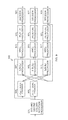
- FIG. 5 illustrates an exemplary block diagram of an apparatus for semi-sequential ILPE, according to one embodiment
- FIG. 6 illustrates an exemplary block diagram of an apparatus for sequential ILPE, according to one embodiment
- FIG. 7 illustrates an exemplary block diagram of an apparatus for wideband/subband ILPE, according to one embodiment
- FIG. 8 illustrates an exemplary block diagram of an apparatus for a Kronecker DFT codebook with multiple and separate layers, according to one embodiment
- FIG. 9 illustrates an exemplary block diagram of an apparatus for a Kronecker DFT codebook with multiple and joint layers, according to one embodiment
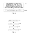
- FIG. 10 illustrates an exemplary flowchart of a method of manufacturing a coarse timing and frequency synchronization apparatus, according to one embodiment.
- FIG. 11 illustrates an exemplary flowchart of a method of constructing an integrated circuit, according to one embodiment
- FIG. 12 illustrates an exemplary block diagram of an apparatus for a parallel version of a Kronecker DFT codebook with multiple and separate layers, according to one embodiment
- FIG. 13 illustrates an exemplary block diagram of an apparatus for sequential ILPE with multiple and separate layers, according to one embodiment
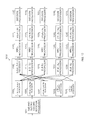
- FIG. 14 illustrates an exemplary block diagram of an apparatus for a parallel version of a wideband/subband single layer Kronecker DFT codebook, according to one embodiment.
- first, second, etc. may be used for describing various elements, the structural elements are not restricted by the terms. The terms are only used to distinguish one element from another element. For example, without departing from the scope of the present disclosure, a first structural element may be referred to as a second structural element. Similarly, the second structural element may also be referred to as the first structural element. As used herein, the term “and/or” includes any and all combinations of one or more associated items.
- the present system and method may be applied to codebooks such as the ones used in LTE, which are based on discrete Fourier transform (DFT) vectors or Kronecker products of DFT vectors.
- DFT discrete Fourier transform
- the present system and method exploits the codebook structure by successively estimating the linear phase ramping in a DFT vector.
- each column of the precoding matrix includes the Kronecker product of 3 DFT vectors: one that determines the beam direction in the horizontal domain, one that determines the beam direction in the vertical domain, and one that determines the co-phasing of cross-polarized antennas.
- the 3 DFT vectors are indexed by 3 variables that may be denoted respectively as l, m, and n.
- the present system determines the dominant eigenvector(s) by SVD of the channel matrix.
- the present system further iteratively estimates coefficients l, m, and n from the linear phase ramping across the elements of the channel eigenvector(s), thereby trying to find the PMI candidate that best matches the phases of the eigenvector(s).
- the present system and method maps the estimated coefficients l, m, and n to the closest possible PMI indices specified by the LTE standard (e.g., refer to 3GPP TS 36.213, Sec. 7.2.4).
- the present system and method directly maps the optimal precoder (e.g., obtained through SVD) to one of the available PMI candidates.
- the present system and method further applies LPE to estimating the coefficient of a DFT vector.
- Q ⁇ . ⁇ PN 1 ⁇ N 2 denotes the total number of transmit antenna ports and L denotes the rank.
- the channel matrix is denoted by H, of size N R ⁇ Q, where N R is the number of antennas at the UE.
- the horizontal and vertical DFT indices are denoted respectively by l and m, and the co-phasing index by n.
- the DFT indices of the second layer are denoted by l′, m′.
- the reported PMI indices are denoted by i 11 , i 12 , i 2 , and their definitions as well as relation to l, m, n are specified in 3GPP TS 36.213, Sec. 7.2.4.
- the optimal precoder or reference precoder may be referred to as a matrix Y ⁇ [y 1 . . . y L ] of size Q ⁇ L having as columns the L dominant eigenvectors of H H H.
- the matrix In the case of a single layer, the matrix consists of a single eigenvector, denoted by y.
- FIG. 1 illustrates an exemplary block diagram of an apparatus for a single DFT codebook, according to one embodiment.
- an apparatus 100 includes an SVD processor 101 , an LPE processor 103 , and a decision processor 105 .
- the SVD processor 101 includes an input for receiving a channel matrix H, and an output for providing samples y of an optimal precoding matrix for H.
- the LPE processor 103 includes an input connected to the output of the SVD processor 101 for receiving the samples y of the optimal precoding matrix for H, and an output for providing a phase estimation of the samples y of the optimal precoding matrix for H.
- the notation “LPE[N 1 ⁇ 1]” for one-dimensional (1D) LPE indicates that LPE is performed using N 1 ⁇ 1 pairs of samples as in Equation (1) below
- the decision processor 105 includes an input connected to the output of the LPE processor 103 , and an output for providing an estimate of a DFT coefficient l.
- the present system estimates the unknown DFT coefficient l by determining an average of multiple distance-1 correlations between all pairs of consecutive samples of y (e.g., y i and y i+1 ), determining a linear phase estimation ⁇ circumflex over ( ⁇ ) ⁇ LPE of such an average, and rounding the determined phase estimate to a nearest integer.
- the decision processor 105 includes an input connected to the LPE processor 103 for receiving ⁇ circumflex over ( ⁇ ) ⁇ LPE , and an output for providing the estimate of the unknown DFT coefficient l. According to one embodiment, the decision processor 105 determines a hard decision concerning the DFT coefficient l estimate as in Equation (2) as follows:
- l ⁇ LPE round ⁇ ( O 1 ⁇ N 1 2 ⁇ ⁇ ⁇ ⁇ ⁇ LPE ) ⁇ ⁇ mod ⁇ ⁇ ( O 1 ⁇ N 1 ) ( 2 )
- round is a function for rounding to a nearest integer
- O 1 is an oversampling factor
- N 1 is the size of the DFT vector.
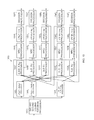
- FIG. 2 illustrates an exemplary block diagram of an apparatus for a parallel version of a single layer Kronecker DFT codebook, according to one embodiment.
- an apparatus 200 includes an SVD processor 201 , a first plurality of LPE processors 203 , 205 , and 207 , a plurality of angle vector processors 209 , 211 , and 213 , a plurality of maximal ratio combining (MRC) processors 215 , 217 , and 219 , a second plurality of LPE processors 221 , 223 , and 225 , and a plurality of decision processors 227 , 229 , and 231 . While FIG.
- FIG. 2 illustrates the SVD processor 201 , the first plurality of LPE processors 203 , 205 , and 207 , the plurality of angle vector processors 209 , 211 , and 213 , the plurality of maximal ratio combining (MRC) processors 215 , 217 , and 219 , the second plurality of LPE processors 221 , 223 , and 225 , and the plurality of decision processors 227 , 229 , and 231 as separate components, these processors may be included in one or more processors.
- MRC maximal ratio combining
- FIG. 2 illustrates the apparatus 200 where a codebook is formed by a Kronecker product of 3 DFT vectors (as in LTE FD-MIMO), hence the apparatus 200 includes 3 branches, one for each variable to be estimated (e.g., l, m, n).
- the present disclosure is not limited thereto and may be extended to different numbers of DFT vectors, without deviating from the scope of the present disclosure.
- the SVD processor 201 includes an input for receiving a channel matrix H, and an output for providing samples y of an optimal precoding matrix for H.
- the SVD processor 201 is illustrated as providing three subvectors of samples (e.g., y 0 , y 1 , and y 2 ).
- each of the first plurality of LPE processors 203 , 205 , and 207 includes an input connected to the output of the SVD processor 201 for receiving one of the subvectors y 0 , y 1 , and y 2 partitioned from samples y of the optimal precoding matrix for H, and an output for providing an initial phase estimation of the corresponding subvectors y 0 , y 1 , and y 2 .
- the LPE processors 203 , 205 , and 207 compute initial estimates ( ⁇ circumflex over ( ⁇ ) ⁇ l , ⁇ circumflex over ( ⁇ ) ⁇ m , ⁇ circumflex over ( ⁇ ) ⁇ n ) of the angles ⁇ l , ⁇ m , ⁇ n (for example, by two-dimensional (2D) LPE).
- 2D LPE may be represented by the notation “LPE k [X,Y],” where X represents the number of sample pairs per vector, Y is the number of vectors combined, and k is an integer indicating the branch.
- the apparatus 200 includes angles
- Estimation of ⁇ l , ⁇ m , and ⁇ n is equivalent to estimating the variables m, l, and n, up to a simple discretization as in Equation (2) above.
- each of the plurality of angle vector processors 209 , 211 , and 213 includes an input connected to a plurality of outputs of the first plurality of LPE processors 203 , 205 , and 207 , and an output for providing one of angle vectors ⁇ circumflex over ( ⁇ ) ⁇ 0 , ⁇ circumflex over ( ⁇ ) ⁇ 1 , ⁇ circumflex over ( ⁇ ) ⁇ 2 computed from a plurality of the initial phase estimates ⁇ circumflex over ( ⁇ ) ⁇ l , ⁇ circumflex over ( ⁇ ) ⁇ m , ⁇ circumflex over ( ⁇ ) ⁇ n .
- the angle vector processor 209 is connected to the LPE processors 205 and 207
- the angle vector processor 211 is connected to the LPE processors 203 and 207
- the angle vector processor 213 is connected to the LPE processors 203 and 205 .
- the present disclosure is not limited thereto.
- Each of the plurality of MRC processors 215 , 217 , and 219 includes an input connected to one of the plurality of angle vector processors 209 , 211 , and 213 , an input connected to the SVD processor 201 , and an output for providing one of a combined vector y 0 , y 1 , or y 2 as expressed in Equations (3), (4), and (5) as follows:
- Each of the second plurality of LPE processors 221 , 223 , and 225 includes an input connected to one of the plurality of MRC processors 215 , 217 , and 219 , and an output for providing a re-estimate ⁇ circumflex over ( ⁇ ) ⁇ l , ⁇ circumflex over ( ⁇ ) ⁇ m , or ⁇ circumflex over ( ⁇ ) ⁇ n of one of the phases of the corresponding subvectors y 0 , y 1 , and y 2 from one of the combined vectors y 0 , y 1 , or y 2 using one-dimensional (1D) LPE.
- 1D LPE may be represented by the notation “LPE k [X],” where X represents the number of sample pairs per vector, and k is an integer indicating the branch.
- Each of the plurality of decision processors 227 , 229 , and 231 converts one of the re-estimated phases ⁇ circumflex over ( ⁇ ) ⁇ l , ⁇ circumflex over ( ⁇ ) ⁇ m , ⁇ circumflex over ( ⁇ ) ⁇ n into a hard estimate of one of ( ⁇ circumflex over (l) ⁇ , ⁇ circumflex over (m) ⁇ , ⁇ circumflex over (n) ⁇ ).
- FIG. 2 A single iteration is illustrated in FIG. 2 . However, the present disclosure is not limited thereto. If there are multiple iterations, the estimates ⁇ circumflex over ( ⁇ ) ⁇ l , ⁇ circumflex over ( ⁇ ) ⁇ m , ⁇ circumflex over ( ⁇ ) ⁇ n before the plurality of decision processors 227 , 229 , and 231 are fed back as input to the plurality of angle vector processors 209 , 211 , and 213 .
- FIG. 3 illustrates an exemplary flowchart for a parallel version of a single layer Kronecker DFT codebook, which is referred to as iterative linear phase estimation (ILPE), according to one embodiment.
- ILPE iterative linear phase estimation
- samples y of an optimal precoding matrix for H are partitioned, by an SVD processor, into subvectors for each of 3 variables at 301 .
- y 1,i+N 2 p,k y i+N 2 k+N 1 N 2 p for i ⁇ 0,1, . . . , N 2 ⁇ 1 ⁇ , k ⁇ 0,1, . . . , N 1 ⁇ 1 ⁇ , p ⁇ 0, . . . , P ⁇ 1 ⁇ , (7)
- y 0,i,k y i+N 1 N 2 k for i ⁇ 0,1, . . . , N 1 N 2 ⁇ 1 ⁇ , k ⁇ 0,1, . . . P ⁇ 1 ⁇ (8)
- initial estimates ( ⁇ circumflex over ( ⁇ ) ⁇ l , ⁇ circumflex over ( ⁇ ) ⁇ m , ⁇ circumflex over ( ⁇ ) ⁇ n ) of angles ⁇ l , ⁇ m , ⁇ n are computed by a first plurality of LPE processors.
- initial estimates ( ⁇ circumflex over ( ⁇ ) ⁇ l , ⁇ circumflex over ( ⁇ ) ⁇ m , ⁇ circumflex over ( ⁇ ) ⁇ n ) of angles ⁇ l , ⁇ m , ⁇ n may be computed by the first plurality of LPE processors using two-dimensional (2D) LPE.
- 2D two-dimensional
- Step 303 may be referred to as two-dimensional (2D) LPE, because multiple vectors are combined before determining the angle, and may be represented by the notation “LPE k [X,Y],” where X represents the number of sample pairs per vector, Y is the number of vectors combined, and k is an integer indicating the branch.
- 2D LPE two-dimensional
- angle vectors ⁇ circumflex over ( ⁇ ) ⁇ 0 , ⁇ circumflex over ( ⁇ ) ⁇ 1 , ⁇ circumflex over ( ⁇ ) ⁇ 2 from the initial estimates of ⁇ circumflex over ( ⁇ ) ⁇ l , ⁇ circumflex over ( ⁇ ) ⁇ n , ⁇ circumflex over ( ⁇ ) ⁇ n are computed by a plurality of angle vector processors.
- ⁇ 0 [0 . . . ( N 2 ⁇ 1) ⁇ m . . . ( N 1 ⁇ 1) ⁇ l . . . ( N 1 ⁇ 1) ⁇ l . . . +( N 2 ⁇ 1) ⁇ m ] T (12)
- ⁇ 1 [0, ⁇ m . . . ( N 2 ⁇ 1) ⁇ m , ⁇ n , ⁇ n + ⁇ m . . . ⁇ n +( N 2 ⁇ 1) ⁇ m ] T (13)
- ⁇ 2 [0, ⁇ l . . . ( N 1 ⁇ 1) ⁇ l , ⁇ n , ⁇ n + ⁇ l . . . ⁇ n +( N 1 ⁇ 1) ⁇ l ] T (14)
- T is a transpose function.
- Equations (12), (13), and (14) The estimates ⁇ circumflex over ( ⁇ ) ⁇ 0 , ⁇ circumflex over ( ⁇ ) ⁇ 1 , ⁇ circumflex over ( ⁇ ) ⁇ 2 are obtained as in Equations (12), (13), and (14) above, respectively, by replacing ⁇ l , ⁇ m , ⁇ n by their estimates ⁇ circumflex over ( ⁇ ) ⁇ l , ⁇ circumflex over ( ⁇ ) ⁇ m , ⁇ circumflex over ( ⁇ ) ⁇ n , respectively, which are either computed at step 303 or, in the case of successive iterations, fed back from a previous iteration.
- MRC is applied to the angle vectors ⁇ circumflex over ( ⁇ ) ⁇ 0 , ⁇ circumflex over ( ⁇ ) ⁇ 1 , ⁇ circumflex over ( ⁇ ) ⁇ 2 by a plurality of MRC processors to obtain combined vectors y 0 , y 1 , y 2 in accordance with Equations (3), (4), and (5) above.
- the re-estimates ⁇ circumflex over ( ⁇ ) ⁇ l , ⁇ circumflex over ( ⁇ ) ⁇ m , ⁇ circumflex over ( ⁇ ) ⁇ n are converted into hard estimates ( ⁇ circumflex over (l) ⁇ , ⁇ circumflex over (m) ⁇ , ⁇ circumflex over (n) ⁇ ) by a plurality of decision processors. Conversion from soft estimates to hard estimates is done as in Equation (2) above, and specifically as in Equations (18), (19), and (20) as follows:
- FIG. 5 illustrates an exemplary block diagram of an apparatus for semi-sequential ILPE, according to one embodiment.
- an apparatus 500 includes an SVD processor 501 , a first plurality of LPE processors 503 and 505 , a plurality of angle vector processors 507 , 509 , and 511 , a plurality of MRC processors 513 , 515 , and 517 , a second plurality of LPE processors 519 , 521 , and 523 , and a plurality of decision processors 525 , 527 , and 529 . While FIG.
- FIG. 5 illustrates the SVD processor 501 , the first plurality of LPE processors 503 and 505 , the plurality of angle vector processors 507 , 509 , and 511 , the plurality of MRC processors 513 , 515 , and 517 , the second plurality of LPE processors 519 , 521 , and 523 , and the plurality of decision processors 525 , 527 , and 529 as separate components, these processors may be included in one or more processors.
- FIG. 5 illustrates the apparatus 500 where a codebook is formed by a Kronecker product of 3 DFT vectors (as in LTE FD-MIMO).
- the apparatus 500 may include 3 branches, one for each variable to be estimated (e.g., l, m, n).
- performance of ILPE may be improved while reducing complexity by estimating different variables sequentially. All (e.g., three) variables may be estimated in parallel at each stage, as illustrated in FIG. 2 .
- ⁇ circumflex over ( ⁇ ) ⁇ 2 may be computed, and m may be estimated by an MRC-based estimation of m.
- An MRC-based estimation of m is of better quality than an initial estimate of m as in FIG. 2 . If the MRC-based estimation of m is used to compute ⁇ circumflex over ( ⁇ ) ⁇ 0 and ⁇ circumflex over ( ⁇ ) ⁇ 1 , the quality of the estimations of l and n is improved. This is referred to as semi-sequential ILPE.
- the order of estimating the variable may be m first, then l, n. It is understood that there may be other orders, without deviating from the scope of the present disclosure.
- the SVD processor 501 includes an input for receiving a channel matrix H, and an output for providing samples y of an optimal precoding matrix for H.
- the SVD processor 501 is illustrated as providing two subvectors of samples (e.g., y 0 and y 1 ).
- each of the first plurality of LPE processors 503 and 505 includes an input connected to the output of the SVD processor 501 for receiving one of the subvectors y 0 and y 1 partitioned from samples y of the optimal precoding matrix for H, and an output for providing an initial phase estimation of the corresponding subvectors y 0 and y 1 .
- the LPE processors 503 and 505 compute initial estimates ( ⁇ circumflex over ( ⁇ ) ⁇ l , ⁇ circumflex over ( ⁇ ) ⁇ n ) of the angles ⁇ l , ⁇ n (for example, by two-dimensional (2D) LPE).
- 2D LPE may be represented by the notation “LPE k [X,Y],” where X represents the number of sample pairs per vector, Y is the number of vectors combined, and k is an integer indicating the branch.
- the apparatus 500 includes angles
- ⁇ l and ⁇ n that represent continuous counterparts of discrete variables l and n.
- Estimation of ⁇ l and ⁇ n is equivalent to estimating the variables l and n, up to a simple discretization as in Equation (2) above.
- An MRC-based estimation of m e.g., ⁇ circumflex over ( ⁇ ) ⁇ m ) is made as described below.
- each of the plurality of angle vector processors 507 , 509 , and 511 includes an input connected to a plurality of outputs of the first plurality of LPE processors 503 and 505 or an output of one of the second plurality of LPE processors 523 from which ⁇ circumflex over ( ⁇ ) ⁇ m is estimated, and an output for providing one of the angle vectors ⁇ circumflex over ( ⁇ ) ⁇ 0 , ⁇ circumflex over ( ⁇ ) ⁇ 1 , ⁇ circumflex over ( ⁇ ) ⁇ 2 computed from a plurality of the initial phase estimates ⁇ circumflex over ( ⁇ ) ⁇ l , ⁇ circumflex over ( ⁇ ) ⁇ m , ⁇ circumflex over ( ⁇ ) ⁇ n .
- the angle vector processor 507 is connected to the LPE processors 505 and 523
- the angle vector processor 509 is connected to the LPE processors 503 and 523
- the angle vector processor 511 is connected to the LPE processors 503 and 505 .
- the present disclosure is not limited thereto.
- Each of the plurality of MRC processors 513 , 515 , and 517 includes an input connected to one of the plurality of angle vector processors 507 , 509 , and 511 , an input from the SVD processor 501 , and an output for providing one of a combined vector y 0 , y 1 , or y 2 as expressed in Equations (3), (4), and (5) above.
- Each of the second plurality of LPE processors 519 , 521 , and 523 includes an input connected to one of the plurality of MRC processors 513 , 515 , and 517 , and an output for providing a re-estimate ⁇ circumflex over ( ⁇ ) ⁇ l , ⁇ circumflex over ( ⁇ ) ⁇ m , or ⁇ circumflex over ( ⁇ ) ⁇ n , of either one of the phases of the corresponding subvectors y 0 and y 1 , or both y 0 and y 1 in the case of estimating ⁇ circumflex over ( ⁇ ) ⁇ m , from one of the combined vectors y 0 and y 1 , or y 2 using LPE.
- the output of the LPE processor 523 is connected to the inputs of the angle vector processors 507 and 509 for providing the MRC-based estimation of m (e.g., ⁇ circumflex over ( ⁇ ) ⁇ m ).
- Each of the plurality of decision processors 525 , 527 , and 529 converts one of the re-estimated phases ⁇ circumflex over ( ⁇ ) ⁇ l or ⁇ circumflex over ( ⁇ ) ⁇ n and the MRC-based estimation of m (e.g., ⁇ circumflex over ( ⁇ ) ⁇ m ) into a hard estimate of one of ( ⁇ circumflex over (l) ⁇ , ⁇ circumflex over (m) ⁇ , ⁇ circumflex over (n) ⁇ ).
- FIG. 5 A single iteration is illustrated in FIG. 5 . However, the present disclosure is not limited thereto. If there are multiple iterations, the estimates ⁇ circumflex over ( ⁇ ) ⁇ l , ⁇ circumflex over ( ⁇ ) ⁇ m , ⁇ circumflex over ( ⁇ ) ⁇ n before the plurality of decision processors 525 , 527 , and 529 are fed back as input to the plurality of angle vector processors 507 , 509 , and 511 .
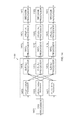
- FIG. 6 illustrates an exemplary block diagram of an apparatus for sequential ILPE, according to one, according to one embodiment.
- the present disclosure may estimate all three variables sequentially (e.g., first m, then l, and finally n).
- an apparatus 600 includes an SVD processor 601 , a first plurality of LPE processors 603 and 605 , a plurality of angle vector processors 607 , 609 , and 611 , a plurality of MRC processors 613 , 615 , and 617 , a second plurality of LPE processors 619 , 621 , and 623 , and a plurality of decision processors 625 , 627 , and 629 . While FIG.
- FIG. 6 illustrates the SVD processor 601 , the first plurality of LPE processors 603 and 605 , the plurality of angle vector processors 607 , 609 , and 611 , the plurality of MRC processors 613 , 615 , and 617 , the second plurality of LPE processors 619 , 621 , and 623 , and the plurality of decision processors 625 , 627 , and 629 as separate components, these processors may be included in one or more processors.
- FIG. 6 illustrates the apparatus 600 where a codebook is formed by a Kronecker product of 3 DFT vectors (as in LTE FD-MIMO).
- the apparatus 600 may include 3 branches, one for each variable to be estimated (e.g., l, m, n).
- performance of ILPE may be improved while reducing complexity by estimating different variables sequentially. All (e.g., three) variables may be estimated in parallel at each stage, as illustrated in FIG. 2 .
- ⁇ circumflex over ( ⁇ ) ⁇ 2 may be computed, and m may be estimated by an MRC-based estimation of m.
- An MRC-based estimation of m is of better quality than an initial estimate of m as in FIG. 2 . If the MRC-based estimation of m is used to compute ⁇ circumflex over ( ⁇ ) ⁇ 1 , the quality of the estimation of l is improved. In addition, If ⁇ circumflex over ( ⁇ ) ⁇ 1 is then used to compute ⁇ circumflex over ( ⁇ ) ⁇ 0 , the quality of the estimation of l is improved. This is referred to as sequential ILPE.
- the order of estimating the variable may be m first, l second, and n third. It is understood that there may be other orders, without deviating from the scope of the present disclosure.
- the SVD processor 601 includes an input for receiving a channel matrix H, and an output for providing samples y of an optimal precoding matrix for H.
- the SVD processor 601 is illustrated as providing two subvectors of samples (e.g., y 0 and y 1 ).
- each of the first plurality of LPE processors 603 and 605 includes an input connected to the output of the SVD processor 601 for receiving one of the subvectors y 0 and y 1 partitioned from samples y of the optimal precoding matrix for H, and an output for providing an initial phase estimation of the corresponding subvectors y 0 and y 1 .
- the LPE processors 603 and 605 compute initial estimates ( ⁇ circumflex over ( ⁇ ) ⁇ 1 , ⁇ circumflex over ( ⁇ ) ⁇ n ) of the angles ⁇ l , ⁇ n (for example, by two-dimensional (2D) LPE).
- 2D LPE may be represented by the notation “LPE k [X,Y],” where X represents the number of sample pairs per vector, Y is the number of vectors combined, and k is an integer indicating the branch.
- the apparatus 600 includes angles
- ⁇ l and ⁇ n that represent continuous counterparts of discrete variables l and n.
- Estimation of ⁇ l and ⁇ n is equivalent to estimating the variables l and n, up to a simple discretization as in Equation (2) above.
- An MRC-based estimation of m e.g., ⁇ circumflex over ( ⁇ ) ⁇ m ) is made as described below.
- each of the plurality of angle vector processors 607 , 609 and 611 includes an input connected to a plurality of outputs of the first plurality of LPE processors 603 and 605 , an output of one of the second plurality of LPE processors 623 from which ⁇ circumflex over ( ⁇ ) ⁇ m is estimated, an output of one of the second plurality of LPE processors 621 from which ⁇ circumflex over ( ⁇ ) ⁇ l is estimated, and an output for providing one of the angle vectors ⁇ circumflex over ( ⁇ ) ⁇ 0 , ⁇ circumflex over ( ⁇ ) ⁇ 1 , ⁇ circumflex over ( ⁇ ) ⁇ 2 computed from a plurality of the initial phase estimates ⁇ circumflex over ( ⁇ ) ⁇ l , ⁇ circumflex over ( ⁇ ) ⁇ m , ⁇ circumflex over ( ⁇ ) ⁇ n .
- the angle vector processor 607 is connected to the LPE processor 621
- the angle vector processor 609 is connected to the LPE processors 603 and 623
- the angle vector processor 611 is connected to the LPE processors 603 and 605 .
- the present disclosure is not limited thereto.
- Each of the plurality of MRC processors 613 , 615 , and 617 includes an input connected to one of the plurality of angle vector processors 607 , 609 , and 611 , an input connected to the SVD processor 601 , and an output for providing one of a combined vector y 1 , y 1 , y 2 as expressed in Equations (3), (4), and (5) above.
- Each of the second plurality of LPE processors 619 , 621 , and 623 includes an input connected to one of the plurality of MRC processors 613 , 615 , and 617 , and an output for providing a re-estimate ⁇ circumflex over ( ⁇ ) ⁇ l , ⁇ circumflex over ( ⁇ ) ⁇ m , or ⁇ circumflex over ( ⁇ ) ⁇ n , from either both y 0 and y 1 in the case of estimating ⁇ circumflex over ( ⁇ ) ⁇ m , both y 0 and the MRC-based estimation of m (e.g., ⁇ circumflex over ( ⁇ ) ⁇ m ) that provides an MRC-based estimation of ⁇ circumflex over ( ⁇ ) ⁇ l , and the MRC-based estimation of ⁇ circumflex over ( ⁇ ) ⁇ l that provides an MRC-based estimation of ⁇ circumflex over ( ⁇ ) ⁇ n , and from one of the combined vectors y 0 and y 1
- the output of LPE processor 623 is connected to the input of the angle vector processor 609 for providing the MRC-based estimation of m (e.g., ⁇ circumflex over ( ⁇ ) ⁇ m ), and the output of the LPE processor 621 is connected to the input of the angle vector processor 607 for providing the MRC-based estimation of l (e.g., ⁇ l ).
- Each of the plurality of decision processors 625 , 627 , and 629 converts one of the MRC-based estimation of m (e.g., ⁇ circumflex over ( ⁇ ) ⁇ m ), the MRC-based estimation of l (e.g., ⁇ circumflex over ( ⁇ ) ⁇ l ), and the MRC-based estimation of n (e.g., ⁇ circumflex over ( ⁇ ) ⁇ n ) into a hard estimate of one of ( ⁇ circumflex over (l) ⁇ , ⁇ circumflex over (m) ⁇ , ⁇ circumflex over (n) ⁇ ).
- m e.g., ⁇ circumflex over ( ⁇ ) ⁇ m
- n e.g., ⁇ circumflex over ( ⁇ ) ⁇ n
- FIG. 6 A single iteration is illustrated in FIG. 6 . However, the present disclosure is not limited thereto. If there are multiple iterations, the estimates ⁇ circumflex over ( ⁇ ) ⁇ l , ⁇ circumflex over ( ⁇ ) ⁇ m , ⁇ circumflex over ( ⁇ ) ⁇ n before the plurality of decision processors 625 , 627 , and 629 are fed back as input to the plurality of angle vector processors 607 , 609 , and 611 .
- FIG. 7 illustrates an exemplary block diagram of an apparatus for wideband/subband ILPE, according to one embodiment.
- part of the PMI report may be wideband (WB), while another part may be per-subband (SB).
- WB wideband
- SB per-subband
- l m is wideband
- n per subband
- N S may be defined as the total number of subcarriers (e.g., 100) and K as the number of subcarriers in one subband (e.g., 8 or 4 for edge subbands).
- the present disclosure may be modified in a number or ways as follows.
- N S subcarriers may be combined in the LPE processors.
- K subcarriers per subband may be combined in the LPE processors.
- ⁇ circumflex over ( ⁇ ) ⁇ n there may be different ⁇ circumflex over ( ⁇ ) ⁇ n , ⁇ circumflex over ( ⁇ ) ⁇ 1 , ⁇ circumflex over ( ⁇ ) ⁇ 2 for different subbands
- ⁇ circumflex over ( ⁇ ) ⁇ l ⁇ circumflex over ( ⁇ ) ⁇ m , ⁇ circumflex over ( ⁇ ) ⁇ 0 are unique for the entire band.
- MRC may be performed separately for each subcarrier. Consequently, the MRC outputs y 0 , y 1 , y 2 may be different for different subcarriers.
- the final LPE processors may perform 2D-LPE, where multiple subcarriers may be combined (e.g., K subcarriers for variable n and N S subcarriers for the wideband variables).
- the hard decision processors may be per-subband for variable n and wideband for the other variables.
- FIG. 7 may be based on the semi-sequential embodiment illustrated in FIG. 5 .
- an apparatus 700 includes an SVD processor 701 , a first plurality of LPE processors 703 and 705 , a plurality of angle vector processors 707 , 709 , and 711 , a plurality of MRC processors 713 , 715 , and 717 , a second plurality of LPE processors 719 , 721 , and 723 , and a plurality of decision processors 725 , 727 , and 729 .
- the SVD processor 701 and the MRC processors 713 , 715 , and 717 represent operations performed for each individual subcarrier; the LPE processors 703 and 719 , the angle vector processors 709 and 711 , and the decision processor 725 represent operations performed for each individual subband); the LPE processors 705 , 721 , and 723 , the angle vector processors 707 , and the decision processors 727 and 729 represent wideband operations.
- the present disclosure is not limited thereto, and other WB/SB embodiments are possible. While FIG.
- FIG. 7 illustrates the SVD processor 701 , the first plurality of LPE processors 703 and 705 , the plurality of angle vector processors 707 , 709 , and 711 , the plurality of MRC processors 713 , 715 , and 717 , the second plurality of LPE processors 719 , 721 , and 723 , and the plurality of decision processors 725 , 727 , and 729 as separate components, these processors may be included in one or more processors.
- FIG. 7 illustrates the apparatus 700 where a codebook is formed by a Kronecker product of 3 DFT vectors (as in LTE FD-MIMO).
- the apparatus 700 may include 3 branches, one for each variable to be estimated (e.g., l, m, n).
- performance of ILPE may be improved while reducing complexity by estimating different variables sequentially. All (e.g., three) variables may be estimated in parallel at each stage, as illustrated in FIG. 2 .
- ⁇ circumflex over ( ⁇ ) ⁇ 2 may be computed, and m may be estimated by an MRC-based estimation of m.
- An MRC-based estimation of m is of better quality than an initial estimate of m as in FIG. 2 . If the MRC-based estimation of m is used to compute ⁇ circumflex over ( ⁇ ) ⁇ 0 and ⁇ circumflex over ( ⁇ ) ⁇ 1 , the quality of the estimations of l and n is improved. This is referred to as semi-sequential ILPE.
- the order of estimating the variable may be m first, then l, n. It is understood that there may be other orders, without deviating from the scope of the present disclosure.
- the SVD processor 701 includes an input for receiving a channel matrix H, and an output for providing samples y of an optimal precoding matrix for H.
- the SVD processor 701 is illustrated as providing two subvectors of samples (e.g., y 0 and y 1 ).
- each of the first plurality of LPE processors 703 and 705 includes an input connected to the output of the SVD processor 701 for receiving one of the subvectors y 0 and y 1 partitioned from samples y of the optimal precoding matrix for H, and an output for providing an initial phase estimation of the corresponding subvectors y 0 and y 1 .
- the LPE processors 703 and 705 compute initial estimates ( ⁇ circumflex over ( ⁇ ) ⁇ l , ⁇ circumflex over ( ⁇ ) ⁇ n ) of the angles ⁇ l , ⁇ n (for example, by two-dimensional (2D) LPE).
- 2D LPE may be represented by the notation “LPE k [X,Y],” where X represents the number of sample pairs per vector, Y is the number of vectors combined, and k is an integer indicating the branch.
- the apparatus 700 includes angles
- Estimation of ⁇ l and ⁇ n is equivalent to estimating the variables l and n, up to a simple discretization as in Equation (2) above.
- An MRC-based estimation of m e.g., ⁇ circumflex over ( ⁇ ) ⁇ m ) is made as described below.
- each of the plurality of angle vector processors 707 , 709 , and 711 includes an input connected to a plurality of outputs of the first plurality of LPE processors 703 and 705 or an output of one of the second plurality of LPE processors 723 from which ⁇ circumflex over ( ⁇ ) ⁇ m is estimated, and an output for providing one of the angle vectors ⁇ circumflex over ( ⁇ ) ⁇ 0 , ⁇ circumflex over ( ⁇ ) ⁇ 1 , ⁇ circumflex over ( ⁇ ) ⁇ 2 computed from a plurality of the initial phase estimates ⁇ circumflex over ( ⁇ ) ⁇ l , ⁇ circumflex over ( ⁇ ) ⁇ m , ⁇ circumflex over ( ⁇ ) ⁇ n .
- the angle vector processor 707 is connected to the LPE processors 705 and 723
- the angle vector processor 709 is connected to the LPE processors 703 and 723
- the angle vector processor 711 is connected to the LPE processors 703 and 705 .
- the present disclosure is not limited thereto.
- Each of the plurality of MRC processors 713 , 715 , and 717 includes a first input connected to one of the plurality of angle vector processors 707 , 709 , and 711 , a second input connected to the output of the SVD processor 701 , and an output for providing one of a combined vector y 0 , y 1 , or y 2 as expressed in Equations (3), (4), and (5) above.
- Each of the second plurality of LPE processors 719 , 721 , and 723 includes an input connected to one of the plurality of MRC processors 713 , 715 , and 717 , and an output for providing a re-estimate ⁇ circumflex over ( ⁇ ) ⁇ l , ⁇ circumflex over ( ⁇ ) ⁇ m , or ⁇ circumflex over ( ⁇ ) ⁇ n of either one of the phases of the corresponding subvectors y 0 and y 1 , or both y 0 and y 1 in the case of estimating ⁇ circumflex over ( ⁇ ) ⁇ m , from one of the combined vectors y 0 and y 1 , or y 2 using LPE.
- the output of the LPE processor 723 is connected to the inputs of the angle vector processors 707 and 709 for providing the MRC-based estimation of m (e.g., ⁇ circumflex over ( ⁇ ) ⁇ m ).
- Each of the plurality of decision processors 725 , 727 , and 729 converts one of the re-estimated phases ⁇ circumflex over ( ⁇ ) ⁇ l or ⁇ circumflex over ( ⁇ ) ⁇ n and the MRC-based estimation of m (e.g., ⁇ circumflex over ( ⁇ ) ⁇ m ) into a hard estimate of one of ( ⁇ circumflex over (l) ⁇ , ⁇ circumflex over (m) ⁇ , ⁇ circumflex over (n) ⁇ ).
- FIG. 7 A single iteration is illustrated in FIG. 7 . However, the present disclosure is not limited thereto. If there are multiple iterations, the estimates ⁇ circumflex over ( ⁇ ) ⁇ l , ⁇ circumflex over ( ⁇ ) ⁇ m , ⁇ circumflex over ( ⁇ ) ⁇ n before the plurality of decision processors 725 , 727 , and 729 are fed back as input to the plurality of angle vector processors 707 , 709 , and 711 .
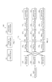
- FIG. 8 illustrates an exemplary block diagram of an apparatus for a Kronecker DFT codebook with multiple and separate layers, according to one embodiment.
- FIG. 8 illustrates an exemplary block diagram for a separate layer (SL) process built upon a semi-sequential embodiment with WB/SB processing.
- SL separate layer
- the present disclosure is not limited thereto. Other combinations are possible, e.g., an SL process built upon an embodiments with or without WB/SB processing.
- the present disclosure may be extended to more than 2 layers by adding more branches for variables (e.g., l′′,m′).
- Equation (21) a codebook for two layers may be of the form expressed in Equation (21) as follows:
- Equation (22) the second half of the second eigenvector is multiplied by ⁇ 1, so as to match the codebook structure.
- ⁇ 1 the two dominant eigenvectors
- y 2 may be processed as expressed in Equation (22) as follows:
- y 2 ′ y 2 ⁇ [ 1 ⁇ 1 - 1 ⁇ - 1 ] ( 22 ) where ⁇ indicates an element-wise product.
- the above pre-processing may be generalized to any phase rotation of any subset of the second column with respect to the first column.
- variables l, m, l′, m′ are estimated independently.
- the embodiment is similar to the embodiment for a single layer, except that there are two additional branches for l′ and m′. n may be common to both layers.
- part of the PMI report may be wideband (WB), while another part may be per-subband (SB).
- WB wideband
- SB per-subband
- l m is wideband
- n per subband
- N S may be defined as the total number of subcarriers (e.g., 100) and K as the number of subcarriers in one subband (e.g., 8 or 4 for edge subbands).
- the present disclosure may be modified in a number or ways as follows.
- N S subcarriers may be combined in the LPE processors.
- K subcarriers per subband may be combined in the LPE processors.
- ⁇ circumflex over ( ⁇ ) ⁇ n there may be different ⁇ circumflex over ( ⁇ ) ⁇ n , ⁇ circumflex over ( ⁇ ) ⁇ 1 , ⁇ circumflex over ( ⁇ ) ⁇ 2 for different subbands
- ⁇ circumflex over ( ⁇ ) ⁇ l ⁇ circumflex over ( ⁇ ) ⁇ m , ⁇ circumflex over ( ⁇ ) ⁇ 0 are unique for the entire band.
- MRC may be performed separately for each subcarrier. Consequently, the MRC outputs y 0 , y 1 , y 2 may be different for different subcarriers.
- the final LPE processors may perform 2D-LPE, where multiple subcarriers may be combined (e.g., K subcarriers for variable n and N S subcarriers for the wideband variables).
- the hard decision processors may be per-subband for variable n and wideband for the other variables.
- FIG. 8 may be based on the semi-sequential embodiment illustrated in FIG. 5 .
- an apparatus 800 includes an SVD processor 801 , a first layer, and a second layer.
- FIG. 8 illustrates the apparatus 800 where a codebook is formed by a Kronecker product of 3 DFT vectors (as in LTE FD-MIMO).
- the apparatus 800 may include 3 branches, one for each variable to be estimated (e.g., l, m, n).
- performance of ILPE may be improved while reducing complexity by estimating different variables sequentially. All (e.g., three) variables may be estimated in parallel at each stage, as illustrated in FIG. 2 .
- ⁇ circumflex over ( ⁇ ) ⁇ 2 may be computed, and m may be estimated by an MRC-based estimation of m.
- An MRC-based estimation of m is of better quality than an initial estimate of m as in FIG. 2 . If the MRC-based estimation of m is used to compute ⁇ circumflex over ( ⁇ ) ⁇ 0 and ⁇ circumflex over ( ⁇ ) ⁇ 1 , the quality of the estimations of l and n is improved. This is referred to as semi-sequential ILPE.
- the order of estimating the variable may be m first, then l, n. It is understood that there may be other orders, without deviating from the scope of the present disclosure.
- the SVD processor 801 includes an input for receiving a channel matrix H, and an output for providing samples y of an optimal precoding matrix for H.
- the SVD processor 801 is illustrated as providing two subvectors of samples (e.g., y 0 and y 1 ).
- the SVD processor 801 rotates a second column as described above.
- the first layer includes a first plurality of LPE processors 803 and 805 , a first plurality of angle vector processors 807 , 809 , and 811 , a first plurality of MRC processors 813 , 815 , and 817 , a second plurality of LPE processors 819 , 821 , and 823 , and a first plurality of decision processors 825 , 827 , and 829 .
- the SVD processor 801 , the LPE processors 803 and 819 , the angle vector processors 809 and 811 , the MRC processors 813 , 815 , and 817 , and the decision processor 825 represent operations performed for each individual subband (or subcarrier, for MRC), while the LPE processors 805 , 821 , and 823 , the angle vector processors 807 , and the decision processors 827 and 829 represent wideband operations.
- the present disclosure is not limited thereto, and other WB/SB embodiments are possible.
- each of the first plurality of LPE processors 803 and 805 includes an input connected to the output of the SVD processor 801 for receiving one of the subvectors y 0 and y 1 partitioned from samples y of the optimal precoding matrix for H, and an output for providing an initial phase estimation of the corresponding subvectors y 0 and y 1 .
- the LPE processors 803 and 805 compute initial estimates ( ⁇ circumflex over ( ⁇ ) ⁇ l , ⁇ circumflex over ( ⁇ ) ⁇ n ) of the angles ⁇ l , ⁇ n (for example, by two-dimensional (2D) LPE).
- 2D LPE may be represented by the notation “LPE k [X,Y],” where X represents the number of sample pairs per vector, Y is the number of vectors combined, and k is an integer indicating the branch.
- the apparatus 800 includes angles
- ⁇ l and ⁇ n that represent continuous counterparts of discrete variables l and n.
- Estimation of ⁇ l and ⁇ n is equivalent to estimating the variables l and n, up to a simple discretization as in Equation (2) above.
- An MRC-based estimation of m e.g., ⁇ circumflex over ( ⁇ ) ⁇ m ) is made as described below.
- each of the first plurality of angle vector processors 807 , 809 , and 811 includes an input connected to a plurality of outputs of the first plurality of LPE processors 803 and 805 or an output of one of the second plurality of LPE processors 823 from which ⁇ circumflex over ( ⁇ ) ⁇ m is estimated, and an output for providing one of the angle vectors ⁇ circumflex over ( ⁇ ) ⁇ 0 , ⁇ circumflex over ( ⁇ ) ⁇ 1 , ⁇ circumflex over ( ⁇ ) ⁇ 2 computed from a plurality of the initial phase estimates ⁇ circumflex over ( ⁇ ) ⁇ 1 , ⁇ circumflex over ( ⁇ ) ⁇ m , ⁇ circumflex over ( ⁇ ) ⁇ n .
- the angle vector processor 807 is connected to the LPE processors 805 , 823 , 831 , and 843
- the angle vector processor 809 is connected to the LPE processors 803 and 823
- the angle vector processor 811 is connected to the LPE processors 803 and 805 .
- the present disclosure is not limited thereto.
- Each of the first plurality of MRC processors 813 , 815 , and 817 includes a first input connected to one of the plurality of angle vector processors 807 , 809 , and 811 , a second input connected to the output of the SVD processor 801 , and an output for providing one of a combined vector y 0 , y 1 , or y 2 as expressed in Equations (3), (4), and (5) above.
- Each of the second plurality of LPE processors 819 , 821 , and 823 includes an input connected to one of the plurality of MRC processors 813 , 815 , and 817 , and an output for providing a re-estimate ⁇ circumflex over ( ⁇ ) ⁇ l , ⁇ circumflex over ( ⁇ ) ⁇ m , or ⁇ circumflex over ( ⁇ ) ⁇ n of either one of the phases of the corresponding subvectors y 0 and y 1 , or both y 0 and y 1 in the case of estimating ⁇ circumflex over ( ⁇ ) ⁇ m , from one of the combined vectors y 0 and y 1 , or y 2 using LPE.
- the output of the LPE processor 823 is connected to the inputs of the angle vector processors 807 and 809 for providing the MRC-based estimation of m (e.g., ⁇ circumflex over ( ⁇ ) ⁇ m ).
- Each of the first plurality of decision processors 825 , 827 , and 829 converts one of the re-estimated phases ⁇ circumflex over ( ⁇ ) ⁇ 1 or ⁇ circumflex over ( ⁇ ) ⁇ n and the MRC-based estimation of m (e.g., ⁇ circumflex over ( ⁇ ) ⁇ m ) into a hard estimate of one of ( ⁇ circumflex over (l) ⁇ , ⁇ circumflex over (m) ⁇ , ⁇ circumflex over (n) ⁇ ).
- FIG. 8 A single iteration is illustrated in FIG. 8 . However, the present disclosure is not limited thereto. If there are multiple iterations, the estimates ⁇ circumflex over ( ⁇ ) ⁇ l , ⁇ circumflex over ( ⁇ ) ⁇ m , ⁇ circumflex over ( ⁇ ) ⁇ n before the first plurality of decision processors 825 , 827 , and 829 are fed back as input to the first plurality of angle vector processors 807 , 809 , and 811 .
- the second layer includes an LPE processor 831 , a second plurality of angle vector processors 833 and 835 , a second plurality of MRC processors 837 and 839 , a third plurality of LPE processors 841 and 843 , and a second plurality of decision processors 845 and 847 .
- the MRC processors 837 and 839 represent operations performed for each individual subcarrier; the angle vector processors 833 and 835 represent operations performed for each individual subband; the LPE processors 831 , 841 , and 843 , and the decision processors 845 and 847 represent wideband operations.
- the present disclosure is not limited thereto, and other WB/SB embodiments are possible.
- the LPE processor 831 includes an input connected to the output of the SVD processor 801 for receiving one of the subvectors y 0 and y 1 partitioned from samples y of the optimal precoding matrix for H, and an output for providing an initial phase estimation of the corresponding subvectors y 0 and y 1 .
- the LPE processor 831 computes an initial estimate ( ⁇ circumflex over ( ⁇ ) ⁇ l′ ) of the angle ⁇ l (for example, by two-dimensional (2D) LPE).
- 2D LPE may be represented by the notation “LPE k [X,Y],” where X represents the number of sample pairs per vector, Y is the number of vectors combined, and k is an integer indicating the branch.
- An MRC-based estimation of m′ (e.g., ⁇ circumflex over ( ⁇ ) ⁇ m′ ) is made as described below.
- each of the plurality of angle vector processors 833 and 835 includes an input connected to a plurality of outputs of the first plurality of LPE processors 803 and 805 and either an output of the LPE processor 831 or an output of one of the second plurality of LPE processors 843 from which ⁇ circumflex over ( ⁇ ) ⁇ m′ is estimated, and an output for providing one of the angle vectors ⁇ circumflex over ( ⁇ ) ⁇ 2 ′, ⁇ circumflex over ( ⁇ ) ⁇ 2 ′ computed from a plurality of the initial phase estimates ⁇ circumflex over ( ⁇ ) ⁇ n , ⁇ circumflex over ( ⁇ ) ⁇ m′ , ⁇ circumflex over ( ⁇ ) ⁇ l′ .
- the angle vector processor 833 is connected to the LPE processors 803 and 843
- the angle vector processor 835 is connected to the LPE processors 803 and 831
- the LPE processor 831 is also connected to the angle vector processors 807 .
- the present disclosure is not limited thereto.
- Each of the plurality of MRC processors 837 and 839 includes a first input connected to one of the plurality of angle vector processors 833 and 835 , a second input connected to the output of the SVD processor 801 , and an output for providing one of a combined vector y 1 ′, or y ′ 2 , which is expressed similarly to Equations (3) and (4) above.
- Each of the third plurality of LPE processors 841 and 843 includes an input connected to one of the plurality of MRC processors 837 and 839 , and an output for providing a re-estimate ⁇ circumflex over ( ⁇ ) ⁇ l ′ or ⁇ circumflex over ( ⁇ ) ⁇ m ′ of either one of the phases of the corresponding subvectors y 1 ′, or y 2 ′ in the case or estimating ⁇ circumflex over ( ⁇ ) ⁇ m′ , from one of the combined vectors y 1 , or y 2 using LPE.
- the output of the LPE processor 843 is connected to the input of the angle vector processor 833 for providing the MRC-based estimation of m′ (e.g., ⁇ circumflex over ( ⁇ ) ⁇ m′ ).
- Each of the second plurality of decision processors 845 and 847 converts one of the re-estimated phases ⁇ circumflex over ( ⁇ ) ⁇ l ′; or ⁇ circumflex over ( ⁇ ) ⁇ m ′ and the MRC-based estimation of m′ (e.g., ⁇ circumflex over ( ⁇ ) ⁇ m′ ) into a hard estimate of one of ( ⁇ circumflex over (l) ⁇ ′, ⁇ circumflex over (m) ⁇ ′).
- FIG. 8 A single iteration is illustrated in FIG. 8 . However, the present disclosure is not limited thereto. If there are multiple iterations, the estimates ⁇ circumflex over ( ⁇ ) ⁇ l ′ and ⁇ circumflex over ( ⁇ ) ⁇ m ′ before the second plurality of decision processors 845 and 847 are fed back as input to the second plurality of angle vector processors 833 and 835 .
- FIG. 8 illustrates the various processors as separate components, they may be included in one or more processors.
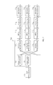
- FIG. 9 illustrates an exemplary block diagram of an apparatus for a Kronecker DFT codebook with multiple and joint layers (JL), according to one embodiment.
- the second half of the second eigenvector is multiplied by ⁇ 1, so as to match the codebook structure. For example, if the two dominant eigenvectors are denoted as [y 1 y 2 ], y 2 may be processed as expressed in Equation (22) above.
- this embodiment is an extension of the single-layer case, just with twice as many samples.
- the number of samples in each LPE block is increased by a factor 2.
- the embodiment may be applied in its semi-sequential version with WB/SB processing, but other combinations are possible. If there are more than 2 layers, the factor 2 is changed accordingly (e.g., 3 for 3 layers etc.).
- one embodiment e.g., estimated variables ⁇ circumflex over (l) ⁇ , ⁇ circumflex over (m) ⁇ , ⁇ circumflex over (n) ⁇
- PMI indices specified in 3GPP TS 36.213 (Sec. 7.2), called i 11 , i 12 , i 2 .
- part of the PMI report may be wideband (WB), while another part may be per-subband (SB).
- WB wideband
- SB per-subband
- l m is wideband
- n per subband
- N S may be defined as the total number of subcarriers (e.g., 100) and K as the number of subcarriers in one subband (e.g., 8 or 4 for edge subbands).
- the present disclosure may be modified in a number or ways as follows.
- N S subcarriers may be combined in the LPE processors.
- K subcarriers per subband may be combined in the LPE processors.
- ⁇ circumflex over ( ⁇ ) ⁇ n there may be different ⁇ circumflex over ( ⁇ ) ⁇ n , ⁇ circumflex over ( ⁇ ) ⁇ 1 , ⁇ circumflex over ( ⁇ ) ⁇ 2 for different subbands
- ⁇ circumflex over ( ⁇ ) ⁇ l ⁇ circumflex over ( ⁇ ) ⁇ m , ⁇ circumflex over ( ⁇ ) ⁇ 0 are unique for the entire band.
- MRC may be performed separately for each subcarrier. Consequently, the MRC outputs y 0 , y 1 , y 2 may be different for different subcarriers.
- the final LPE processors may perform 2D-LPE, where multiple subcarriers may be combined (e.g., K subcarriers for variable n and N S subcarriers for the wideband variables).
- the hard decision processors may be per-subband for variable n and wideband for the other variables.
- FIG. 9 may be based on the semi-sequential embodiment illustrated in FIG. 5 .
- an apparatus 900 includes an SVD processor 901 , a first plurality of LPE processors 903 and 905 , a plurality of angle vector processors 907 , 909 , and 911 , a plurality of MRC processors 913 , 915 , and 917 , a second plurality of LPE processors 919 , 921 , and 923 , and a plurality of decision processors 925 , 927 , and 929 .
- the SVD processor 901 and the MRC processors 913 , 915 , and 917 represent operations performed for each individual subcarrier; the LPE processors 903 and 919 , the angle vector processors 909 and 911 , and the decision processor 925 represent operations performed for each individual subband; while the LPE processors 905 , 921 , and 923 , the angle vector processors 907 , and the decision processors 927 and 929 represent wideband operations.
- the present disclosure is not limited thereto, and other WB/SB embodiments are possible. While FIG.
- FIG. 9 illustrates the SVD processor 901 , the first plurality of LPE processors 903 and 905 , the plurality of angle vector processors 907 , 909 , and 911 , the plurality of MRC processors 913 , 915 , and 917 , the second plurality of LPE processors 919 , 921 , and 923 , and the plurality of decision processors 925 , 927 , and 929 as separate components, these processors may be included in one or more processors.
- FIG. 9 illustrates the apparatus 900 where a codebook is formed by a Kronecker product of 3 DFT vectors (as in LTE FD-MIMO).
- the apparatus 900 may include 3 branches, one for each variable to be estimated (e.g., l, m, n).
- performance of ILPE may be improved while reducing complexity by estimating different variables sequentially. All (e.g., three) variables may be estimated in parallel at each stage, as illustrated in FIG. 2 .
- ⁇ circumflex over ( ⁇ ) ⁇ 2 may be computed, and m may be estimated by an MRC-based estimation of m.
- An MRC-based estimation of m is of better quality than an initial estimate of m as in FIG. 2 . If the MRC-based estimation of m is used to compute ⁇ circumflex over ( ⁇ ) ⁇ 0 and ⁇ circumflex over ( ⁇ ) ⁇ 1 , the quality of the estimations of l and n is improved. This is referred to as semi-sequential ILPE.
- the order of estimating the variable may be m first, then l, n. It is understood that there may be other orders, without deviating from the scope of the present disclosure.
- the SVD processor 901 includes an input for receiving a channel matrix H, and an output for providing samples y of an optimal precoding matrix for H.
- the SVD processor 901 is illustrated as providing two samples (e.g., y 0 and y 1 ).
- each of the first plurality of LPE processors 903 and 905 includes an input connected to the output of the SVD processor 901 for receiving one of the subvectors y 0 and y 1 partitioned from samples y of the optimal precoding matrix for H, and an output for providing an initial phase estimation of the corresponding subvectors y 0 and y 1 .
- the LPE processors 903 and 905 compute initial estimates ( ⁇ circumflex over ( ⁇ ) ⁇ l , ⁇ circumflex over ( ⁇ ) ⁇ n ) of the angles ⁇ l , ⁇ n (for example, by two-dimensional (2D) LPE).
- 2D LPE may be represented by the notation “LPE k [X,Y],” where X represents the number of sample pairs per vector, Y is the number of vectors combined, and k is an integer indicating the branch.
- the apparatus 900 includes angles
- Estimation of ⁇ l and ⁇ n is equivalent to estimating the variables l and n, up to a simple discretization as in Equation (2) above.
- An MRC-based estimation of m e.g., ⁇ circumflex over ( ⁇ ) ⁇ m ) is made as described below.
- each of the plurality of angle vector processors 907 , 909 , and 911 includes an input connected to a plurality of outputs of the first plurality of LPE processors 903 and 905 or an output of one of the second plurality of LPE processors 923 from which ⁇ circumflex over ( ⁇ ) ⁇ m is estimated, and an output for providing one of the angle vectors ⁇ circumflex over ( ⁇ ) ⁇ 0 , ⁇ circumflex over ( ⁇ ) ⁇ 1 , ⁇ circumflex over ( ⁇ ) ⁇ 2 computed from a plurality of the initial phase estimates ⁇ circumflex over ( ⁇ ) ⁇ l , ⁇ circumflex over ( ⁇ ) ⁇ m , ⁇ circumflex over ( ⁇ ) ⁇ n .
- the angle vector processor 907 is connected to the LPE processors 905 and 923
- the angle vector processor 909 is connected to the LPE processors 903 and 923
- the angle vector processor 911 is connected to the LPE processors 903 and 905 .
- the present disclosure is not limited thereto.
- Each of the plurality of MRC processors 913 , 915 , and 917 includes a first input connected to one of the plurality of angle vector processors 907 , 909 , and 911 , a second input connected to the output of the SVD processor 901 , and an output for providing one of a combined vector y 0 , y 1 , or y 2 as expressed in Equations (3), (4), and (5) above.
- Each of the second plurality of LPE processors 919 , 921 , and 923 includes an input connected to one of the plurality of MRC processors 913 , 915 , and 917 , and an output for providing a re-estimate ⁇ circumflex over ( ⁇ ) ⁇ l , ⁇ circumflex over ( ⁇ ) ⁇ m , or ⁇ circumflex over ( ⁇ ) ⁇ n of either one of the phases of the corresponding subvectors y 0 and y 1 , or both y 0 and y 1 in the case of estimating ⁇ circumflex over ( ⁇ ) ⁇ m , from one of the combined vectors y 0 and y 1 , or y 2 using LPE.
- the output of LPE processor 923 is connected to the inputs of LPE processors 907 and 909 for providing the MRC-based estimation of m (e.g., ⁇ circumflex over ( ⁇ ) ⁇ m ).
- Each of the plurality of decision processors 925 , 927 , and 929 converts one of the re-estimated phases ⁇ circumflex over ( ⁇ ) ⁇ l or ⁇ circumflex over ( ⁇ ) ⁇ n and the MRC-based estimation of m (e.g., ⁇ circumflex over ( ⁇ ) ⁇ m ) into a hard estimate of one of ( ⁇ circumflex over (l) ⁇ , ⁇ circumflex over (m) ⁇ , ⁇ circumflex over (n) ⁇ ).
- FIG. 9 A single iteration is illustrated in FIG. 9 . However, the present disclosure is not limited thereto. If there are multiple iterations, the estimates ⁇ circumflex over ( ⁇ ) ⁇ l , ⁇ circumflex over ( ⁇ ) ⁇ m , ⁇ circumflex over ( ⁇ ) ⁇ n before the plurality of decision processors 925 , 927 , and 929 are fed back as input to the plurality of angle vector processors 907 , 909 , and 911 .
- LPE with correlation distance D may be used whenever the number of samples in the input vector of LPE is at least D+1.
- Equation (1) above may be modified as follows:
- FIG. 10 illustrates an exemplary flowchart of a method of manufacturing an apparatus, according to one embodiment.
- an apparatus is formed on a wafer or a package with at least one other apparatus, where the apparatus includes an SVD processor, an LPE processor, and a decision processor at 1001 .
- Testing the apparatus may include testing the apparatus using one or more electrical to optical converters, one or more optical splitters that split an optical signal into two or more optical signals, and one or more optical to electrical converters.
- FIG. 11 illustrates an exemplary flowchart of a method of constructing an integrated circuit, according to one embodiment.
- initial layout data is constructed in 1101 .
- a mask layout is generated for a set of features for a layer of the integrated circuit, wherein the mask layout includes standard cell library macros for one or more circuit features that include An apparatus that includes an SVD processor, an LPE processor, and a decision processor, and disregarding relative positions of the macros for compliance to layout design rules during the generation of the mask layout.
- a design rule check is performed.
- the method may check the relative positions of the macros for compliance to layout design rules after generating the mask layout.
- the layout is adjusted.
- the method upon detection of noncompliance with the layout design rules by any of the macros, may modify the mask layout by modifying each of the noncompliant macros to comply with the layout design rules.
- new layout data is generated.
- the method may generate a mask according to the modified mask layout with the set of features for the layer of the integrated circuit. Then, the integrated circuit layer according to the mask may be manufactured.
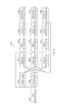
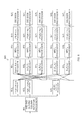
- FIG. 12 illustrates an exemplary block diagram of an apparatus for a parallel version of a Kronecker DFT codebook with multiple and separate layers, according to one embodiment.
- an apparatus 1200 includes an SVD and second column rotation processor 1201 , a first layer, and a second layer.
- FIG. 12 illustrates the apparatus 1200 where a codebook is formed by a Kronecker product of 3 DFT vectors (as in LTE FD-MIMO).
- the apparatus 1200 may include 3 branches, one for each variable to be estimated (e.g., l, m, n). All (e.g., three) variables are estimated in parallel at each stage, as illustrated in FIG. 2 .
- the SVD and second column rotation processor 1201 includes an input for receiving a channel matrix H, and an output for providing samples y of an optimal precoding matrix for H.
- the SVD and second column rotation processor 1201 is illustrated as providing two subvectors of samples (e.g., y 0 and y 1 ).
- the SVD and second column rotation processor 1201 rotates a second column as described above.
- the first layer includes a first plurality of LPE processors 1203 , 1205 , and 1207 , a first plurality of angle vector processors 1209 , 1211 , and 1213 , a first plurality of MRC processors 1215 , 1217 , and 1219 , a second plurality of LPE processors 1221 , 1223 , and 1225 , and a first plurality of decision processors 1227 , 1229 , and 1231 .
- each of the first plurality of LPE processors 1203 , 1205 , and 1207 includes an input connected to the output of the SVD and second column rotation processor 1201 for receiving one of the subvectors y 0 , y 1 , and y 2 partitioned from samples y of the optimal precoding matrix for H, and an output for providing an initial phase estimation of the corresponding subvectors y 0 , y 1 , and y 2 .
- the LPE processors 1203 , 1205 , and 1207 compute initial estimates ( ⁇ circumflex over ( ⁇ ) ⁇ l , ⁇ circumflex over ( ⁇ ) ⁇ m , ⁇ circumflex over ( ⁇ ) ⁇ n ) of the angles ⁇ circumflex over ( ⁇ ) ⁇ l , ⁇ circumflex over ( ⁇ ) ⁇ m , ⁇ circumflex over ( ⁇ ) ⁇ n , (for example, by two-dimensional (2D) LPE).
- 2D LPE may be represented by the notation “LPE k [X,Y],” where X represents the number of sample pairs per vector, Y is the number of vectors combined, and k is an integer indicating the branch.
- the apparatus 1200 includes angles
- ⁇ l ⁇ . ⁇ 2 ⁇ ⁇ O 1 ⁇ N 1 ⁇ l
- ⁇ m ⁇ . ⁇ 2 ⁇ ⁇ O 2 ⁇ N 2 ⁇ m
- ⁇ n ⁇ . ⁇ ⁇ 2 ⁇ n , that represent continuous counterparts of discrete variables l, m, and n.
- Estimation of ⁇ l , ⁇ m , and ⁇ n is equivalent to estimating the variables m, l, and n, up to a simple discretization as in Equation (2) above.
- each of the first plurality of angle vector processors 1209 , 1211 , and 1213 includes an input connected to a plurality of outputs of the first plurality of LPE processors 1203 , 1205 , and 1207 , and an output for providing one of the angle vectors ⁇ circumflex over ( ⁇ ) ⁇ 0 , ⁇ circumflex over ( ⁇ ) ⁇ 1 , ⁇ circumflex over ( ⁇ ) ⁇ 2 computed from a plurality of the initial phase estimates ⁇ circumflex over ( ⁇ ) ⁇ l , ⁇ circumflex over ( ⁇ ) ⁇ m , ⁇ circumflex over ( ⁇ ) ⁇ n .
- the angle vector processor 1209 is also connected to the LPE processors 1233 and 1235 in the third plurality of LPE processors in the second layer.
- the angle vector processor 1209 is connected to the LPE processors 1205 and 1207
- the angle vector processor 1211 is connected to the LPE processors 1203 and 1207
- the angle vector processor 1213 is connected to the LPE processors 1203 and 1205 .
- the present disclosure is not limited thereto.
- Each of the first plurality of MRC processors 1215 , 1217 , and 1219 includes a first input connected to one of the plurality of angle vector processors 1209 , 1211 , and 1213 , a second input connected to the output of the SVD and second column rotation processor 1201 , and an output for providing one of a combined vector y 0 , y 1 , or y 2 as expressed in Equations (3), (4), and (5) above.
- Each of the second plurality of LPE processors 1221 , 1223 , and 1225 includes an input connected to one of the plurality of MRC processors 1215 , 1217 , and 1219 , and an output for providing a re-estimate ⁇ circumflex over ( ⁇ ) ⁇ l , ⁇ circumflex over ( ⁇ ) ⁇ m , or ⁇ circumflex over ( ⁇ ) ⁇ n of either one of the phases of the corresponding subvectors y 0 , y 1 , and y 2 .
- Each of the first plurality of decision processors 1227 , 1229 , and 1231 converts one of the re-estimated phases ⁇ circumflex over ( ⁇ ) ⁇ l , ⁇ circumflex over ( ⁇ ) ⁇ m , or ⁇ circumflex over ( ⁇ ) ⁇ n into a hard estimate of one of ( ⁇ circumflex over (l) ⁇ , ⁇ circumflex over (m) ⁇ , ⁇ circumflex over (n) ⁇ ).
- FIG. 12 A single iteration is illustrated in FIG. 12 . However, the present disclosure is not limited thereto. If there are multiple iterations, the estimates ⁇ circumflex over ( ⁇ ) ⁇ l , ⁇ circumflex over ( ⁇ ) ⁇ m , ⁇ circumflex over ( ⁇ ) ⁇ n before the first plurality of decision processors 1227 , 1229 , and 1231 are fed back as input to the first plurality of angle vector processors 1209 , 1211 , and 1213 .
- the second layer includes a third plurality of LPE processors 1233 and 1235 , a second plurality of angle vector processors 1237 and 1239 , a second plurality of MRC processors 1241 and 1243 , a fourth plurality of LPE processors 1245 and 1247 , and a second plurality of decision processors 1249 and 1251 .
- each of the third plurality of LPE processors 1233 and 1235 includes an input connected to the output of the SVD and second column rotation processor 1201 for receiving one of the subvectors y 1 and y 2 partitioned from samples y of the optimal precoding matrix for H, and an output for providing an initial phase estimation of the corresponding subvectors y 1 and y 2 .
- Each of the third plurality of LPE processors 1233 and 1235 computes an initial estimate ( ⁇ circumflex over ( ⁇ ) ⁇ l′ , ⁇ circumflex over ( ⁇ ) ⁇ m′ ) of the angles ⁇ l and ⁇ m (for example, by two-dimensional (2D) LPE).
- 2D LPE may be represented by the notation “LPE k [X,Y],” where X represents the number of sample pairs per vector, Y is the number of vectors combined, and k is an integer indicating the branch.
- each of the second plurality of angle vector processors 1237 and 1239 includes an input connected to one of the outputs of the first plurality of LPE processors 1203 , 1205 , and 1207 and an output of one of the third plurality of LPE processor 1233 and 1235 , and an output for providing one of the angle vectors ⁇ circumflex over ( ⁇ ) ⁇ 2 ′, ⁇ circumflex over ( ⁇ ) ⁇ 2 ′ computed from a plurality of the initial phase estimates ⁇ circumflex over ( ⁇ ) ⁇ n , ⁇ circumflex over ( ⁇ ) ⁇ m ′, ⁇ circumflex over ( ⁇ ) ⁇ l ′.
- the angle vector processor 1237 is connected to the LPE processors 1203 and 1235
- the angle vector processor 1239 is connected to the LPE processors 1203 and 1233 .
- the present disclosure is not limited thereto.
- Each of the second plurality of MRC processors 1241 and 1243 includes a first input connected to one of the second plurality of angle vector processors 1237 and 1239 , a second input connected to the output of the SVD and second column rotation processor 1201 , and an output for providing one of a combined vector y 1 ′, or y 2 ′, which is expressed similarly to Equations (3) and (4) above.
- Each of the second plurality of decision processors 1249 and 1251 converts one of the re-estimated phases ⁇ circumflex over ( ⁇ ) ⁇ l ′ or ⁇ circumflex over ( ⁇ ) ⁇ m ′ into a hard estimate of one of ( ⁇ circumflex over (l) ⁇ ′, ⁇ circumflex over (m) ⁇ ′).
- FIG. 12 A single iteration is illustrated in FIG. 12 . However, the present disclosure is not limited thereto. If there are multiple iterations, the estimates ⁇ circumflex over ( ⁇ ) ⁇ l ′ and ⁇ circumflex over ( ⁇ ) ⁇ m ′ before the second plurality of decision processors 1249 and 1251 are fed back as input to the second plurality of angle vector processors 1237 and 1239 .
- FIG. 12 illustrates the various processors as separate components, they may be included in one or more processors.
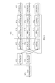
- FIG. 13 illustrates an exemplary block diagram of an apparatus for sequential ILPE with multiple and separate layers, according to one embodiment.
- an apparatus 1300 includes an SVD and second column rotation processor 1301 , a first layer, and a second layer.
- FIG. 13 illustrates the apparatus 1300 where a codebook is formed by a Kronecker product of 3 DFT vectors (as in LTE FD-MIMO).
- the apparatus 1300 may include 3 branches, one for each variable to be estimated (e.g., l, m, n).
- performance of ILPE may be improved while reducing complexity by estimating different variables sequentially. All (e.g., three) variables may be estimated in parallel at each stage, as illustrated in FIG. 2 .
- ⁇ circumflex over ( ⁇ ) ⁇ 2 , ⁇ circumflex over ( ⁇ ) ⁇ 1 ′, and ⁇ circumflex over ( ⁇ ) ⁇ 2 ′ may be computed, and m, m′, and l′ may be estimated by MRC-based estimations of m, m′, and l′.
- MRC-based estimation of m, m′, and l′ are of better quality than initial estimates of m, m′, and l′ as in FIG. 2 .
- the quality of the estimations of l and n is improved. This is referred to as semi-sequential ILPE in separate layers.
- the order of estimating the variables may be m first, then l, n. It is understood that there may be other orders, without deviating from the scope of the present disclosure.
- the SVD and second column rotation processor 1301 includes an input for receiving a channel matrix H, and an output for providing samples y of an optimal precoding matrix for H.
- the SVD and second column rotation processor 1301 is illustrated as providing two subvectors of samples (e.g., y 0 and y 1 ).
- the SVD and second column rotation processor 1301 rotates a second column as described above.
- the first layer includes a first plurality of LPE processors 1303 and 1305 , a first plurality of angle vector processors 1307 , 1309 , and 1311 , a first plurality of MRC processors 1313 , 1315 , and 1317 , a second plurality of LPE processors 1319 , 1321 , and 1323 , and a first plurality of decision processors 1325 , 1327 , and 1329 .
- each of the first plurality of LPE processors 1303 and 1305 includes an input connected to the output of the SVD and second column rotation processor 1301 for receiving one of the subvectors y 0 and y 1 partitioned from samples y of the optimal precoding matrix for H, and an output for providing an initial phase estimation of the corresponding subvectors y 0 and y 1 .
- the LPE processors 1303 and 1305 compute initial estimates ( ⁇ circumflex over ( ⁇ ) ⁇ l , ⁇ circumflex over ( ⁇ ) ⁇ n ) of the angles ⁇ l , ⁇ n (for example, by two-dimensional (2D) LPE).
- 2D LPE may be represented by the notation “LPE k [X,Y],” where X represents the number of sample pairs per vector, Y is the number of vectors combined, and k is an integer indicating the branch.
- the apparatus 1300 includes angles
- ⁇ l and ⁇ n that represent continuous counterparts of discrete variables l and n.
- Estimation of ⁇ l and ⁇ n is equivalent to estimating the variables l and n, up to a simple discretization as in Equation (2) above.
- An MRC-based estimation of m e.g., ⁇ circumflex over ( ⁇ ) ⁇ m ) is made as described below.
- each of the first plurality of angle vector processors 1307 , 1309 , and 1311 includes an input connected to at least one output of LPE processors 1303 , 1305 , or an output of one of the LPE processors 1323 , 1341 , or 1343 from which ⁇ circumflex over ( ⁇ ) ⁇ m , ⁇ circumflex over ( ⁇ ) ⁇ l ′, and ⁇ circumflex over ( ⁇ ) ⁇ m ′, are estimated, and an output for providing one of the angle vectors ⁇ circumflex over ( ⁇ ) ⁇ 0 , ⁇ circumflex over ( ⁇ ) ⁇ 1 , ⁇ circumflex over ( ⁇ ) ⁇ 2 computed from a plurality of the initial phase estimates ⁇ circumflex over ( ⁇ ) ⁇ l , ⁇ circumflex over ( ⁇ ) ⁇ m , ⁇ circumflex over ( ⁇ ) ⁇ n , ⁇ circumflex over ( ⁇ ) ⁇ l ′, and ⁇ circumflex over ( ⁇ ) ⁇ m
- the angle vector processor 1307 is connected to the LPE processors 1323 , 1341 , and 1343
- the angle vector processor 1309 is connected to the LPE processors 1303 and 1323
- the angle vector processor 1311 is connected to the LPE processors 1303 and 1305 .
- the present disclosure is not limited thereto.
- Each of the first plurality of MRC processors 1313 , 1315 , and 1317 includes a first input connected to one of the plurality of angle vector processors 1307 , 1309 , and 1311 , a second input connected to the output of the SVD and second column rotation processor 1301 , and an output for providing one of a combined vector y 0 , y 1 , or y 2 as expressed in Equations (3), (4), and (5) above.
- Each of the second plurality of LPE processors 1319 , 1321 , and 1323 includes an input connected to one of the plurality of MRC processors 1313 , 1315 , and 1317 , and an output for providing a re-estimate ⁇ circumflex over ( ⁇ ) ⁇ l , ⁇ circumflex over ( ⁇ ) ⁇ m , or ⁇ circumflex over ( ⁇ ) ⁇ n of either one of the phases of the corresponding subvectors y 0 and y 1 , or both y 0 and y 1 in the case of estimating ⁇ circumflex over ( ⁇ ) ⁇ m , from one of the combined vectors y 0 and y 1 , or y 2 using LPE.
- the output of the LPE processor 1323 is connected to the inputs of the angle vector processors 1307 and 1309 for providing the MRC-based estimation of m (e.g., ⁇ circumflex over ( ⁇ ) ⁇ m ).
- Each of the first plurality of decision processors 1325 , 1327 , and 1329 converts one of the re-estimated phases ⁇ circumflex over ( ⁇ ) ⁇ l or ⁇ circumflex over ( ⁇ ) ⁇ n and the MRC-based estimation of m (e.g., ⁇ circumflex over ( ⁇ ) ⁇ m ), m′ (e.g., ⁇ circumflex over ( ⁇ ) ⁇ ′ m ), and l′ (e.g., ⁇ circumflex over ( ⁇ ) ⁇ ′ l ) into a hard estimate of one of ( ⁇ circumflex over (l) ⁇ , ⁇ circumflex over (m) ⁇ , ⁇ circumflex over (n) ⁇ ).
- m e.g., ⁇ circumflex over ( ⁇ ) ⁇ m
- m′ e.g., ⁇ circumflex over ( ⁇ ) ⁇ ′ m
- l′ e.g., ⁇ circumflex over ( ⁇ ) ⁇ ′ l
- FIG. 13 A single iteration is illustrated in FIG. 13 .
- the present disclosure is not limited thereto. If there are multiple iterations, the estimates ⁇ circumflex over ( ⁇ ) ⁇ l , ⁇ circumflex over ( ⁇ ) ⁇ m , ⁇ circumflex over ( ⁇ ) ⁇ n , ⁇ circumflex over ( ⁇ ) ⁇ ′ m , and ⁇ circumflex over ( ⁇ ) ⁇ ′ l before the first plurality of decision processors 1325 , 1327 , and 1329 are fed back as input to the first plurality of angle vector processors 1307 , 1309 , and 1311 .
- the second layer includes an LPE processor 1331 , a second plurality of angle vector processors 1333 and 1335 , a second plurality of MRC processors 1337 and 1339 , a third plurality of LPE processors 1341 and 1343 , and a second plurality of decision processors 1345 and 1347 .
- the LPE processor 1331 includes an input connected to the output of the SVD and second column rotation processor 1301 for receiving one of the subvectors y 0 and y 1 partitioned from samples y of the optimal precoding matrix for H, and an output for providing an initial phase estimation of the corresponding subvectors y 0 and y 1 .
- the LPE processor 1331 computes an initial estimate ( ⁇ circumflex over ( ⁇ ) ⁇ l′ ) of the angle ⁇ l (for example, by two-dimensional (2D) LPE).
- 2D LPE may be represented by the notation “LPE k [X,Y],” where X represents the number of sample pairs per vector, Y is the number of vectors combined, and k is an integer indicating the branch.
- An MRC-based estimation of m′ (e.g., ⁇ circumflex over ( ⁇ ) ⁇ m′ ) is made as described below.
- each of the plurality of angle vector processors 1333 and 1335 includes an input connected to an output of one of the first plurality of LPE processors 1303 and 1305 and either an output of the LPE processor 1331 or an output of one of the second plurality of LPE processors 1343 from which ⁇ circumflex over ( ⁇ ) ⁇ m′ is estimated, and an output for providing one of the angle vectors ⁇ circumflex over ( ⁇ ) ⁇ 2 ′, ⁇ circumflex over ( ⁇ ) ⁇ 2 ′ computed from a plurality of the initial phase estimates ⁇ circumflex over ( ⁇ ) ⁇ n , ⁇ circumflex over ( ⁇ ) ⁇ m′ , ⁇ circumflex over ( ⁇ ) ⁇ l′ .
- the angle vector processor 1333 is connected to the LPE processors 1303 and 1343
- the angle vector processor 1335 is connected to the LPE processors 1303 and 1331 .
- the present disclosure is not limited thereto.
- Each of the plurality of MRC processors 1337 and 1339 includes a first input connected to one of the plurality of angle vector processors 1333 and 1335 , a second input connected to the output of the SVD and second column rotation processor 1301 , and an output for providing one of a combined vector y 1 ′, or y 2 ′, which is expressed similarly to Equations (3) and (4) above.
- Each of the third plurality of LPE processors 1341 and 1343 includes an input connected to one of the plurality of MRC processors 1337 and 1339 , and an output for providing a re-estimate ⁇ l ′ or ⁇ m ′ of either one of the phases of the corresponding subvectors y 1 ′ , or y 2 ′ in the case of estimating ⁇ circumflex over ( ⁇ ) ⁇ m′ , from one of the combined vectors y 1 , or y 2 using LPE.
- the output of the LPE processor 1341 is connected to the inputs of the angle vector processor 1307 .
- the output of the LPE processor 1343 is connected to the input of the angle vector processors 1307 and 1333 for providing the MRC-based estimation of m′ (e.g., ⁇ circumflex over ( ⁇ ) ⁇ m′ ).
- Each of the second plurality of decision processors 1345 and 1347 converts one of the re-estimated phases ⁇ circumflex over ( ⁇ ) ⁇ l ′ or ⁇ circumflex over ( ⁇ ) ⁇ m ′ and the MRC-based estimation of m′ (e.g., ⁇ circumflex over ( ⁇ ) ⁇ m′ ) into a hard estimate of one of ( ⁇ circumflex over (l) ⁇ ′, ⁇ circumflex over (m) ⁇ ′).
- FIG. 13 A single iteration is illustrated in FIG. 13 . However, the present disclosure is not limited thereto. If there are multiple iterations, the estimates ⁇ circumflex over ( ⁇ ) ⁇ l ′ and ⁇ circumflex over ( ⁇ ) ⁇ m ′ before the second plurality of decision processors 1345 and 1347 are fed back as input to the second plurality of angle vector processors 1333 and 1335 .
- FIG. 13 illustrates the various processors as separate components, they may be included in one or more processors.
- part of the PMI report may be wideband (WB), while another part may be per-subband (SB).
- WB wideband
- SB per-subband
- l m is wideband
- n per subband
- N S may be defined as the total number of subcarriers (e.g., 100) and K as the number of subcarriers in one subband (e.g., 8 or 4 for edge subbands).
- the present disclosure may be modified in a number or ways as follows.
- N S subcarriers may be combined in the LPE processors.
- K subcarriers per subband may be combined in the LPE processors.
- ⁇ circumflex over ( ⁇ ) ⁇ n there may be different ⁇ circumflex over ( ⁇ ) ⁇ n , ⁇ circumflex over ( ⁇ ) ⁇ 1 , ⁇ circumflex over ( ⁇ ) ⁇ 2 for different subbands
- ⁇ circumflex over ( ⁇ ) ⁇ l ⁇ circumflex over ( ⁇ ) ⁇ m , ⁇ circumflex over ( ⁇ ) ⁇ 0 are unique for the entire band.
- MRC may be performed separately for each subcarrier. Consequently, the MRC outputs y 0 , y 1 , y 2 may be different for different subcarriers.
- the final LPE processors may perform 2D-LPE, where multiple subcarriers may be combined (e.g., K subcarriers for variable n and N S subcarriers for the wideband variables).
- the hard decision processors may be per-subband for variable n and wideband for the other variables.
- FIG. 14 may be based on the parallel version of a single layer Kronecker DFT codebook embodiment illustrated in FIG. 2 .
- FIG. 14 illustrates an exemplary block diagram of an apparatus for a parallel version of a wideband/subband single layer Kronecker DFT codebook, according to one embodiment.
- an apparatus 1400 includes an SVD processor 1401 , a first plurality of LPE processors 1403 , 1405 , and 1407 , a plurality of angle vector processors 1409 , 1411 , and 1413 , a plurality of MRC processors 1415 , 1417 , and 1419 , a second plurality of LPE processors 1421 , 1423 , and 1425 , and a plurality of decision processors 1427 , 1429 , and 1431 .
- the SVD processor 1401 and the MRC processors 1415 , 1417 , and 1419 represent operations performed for each individual subcarrier; the LPE processors 1403 and 1421 , the angle vector processors 1411 and 1413 , and the decision processor 1427 represent operations performed for each individual subband); the LPE processors 1405 , 1407 , 1423 , and 1425 , the angle vector processors 1409 , and the decision processors 1429 and 1431 represent wideband operations.
- the present disclosure is not limited thereto, and other WB/SB embodiments are possible. While FIG.
- FIG. 14 illustrates the SVD processor 1401 , the first plurality of LPE processors 1403 , 1405 , and 1407 , the plurality of angle vector processors 1409 , 1411 , and 1413 , the plurality of MRC processors 1415 , 1417 , and 1419 , the second plurality of LPE processors 1421 , 1423 , and 1425 , and the plurality of decision processors 1427 , 1429 , and 1431 as separate components, these processors may be included in one or more processors.
- FIG. 14 illustrates the apparatus 1400 where a codebook is formed by a Kronecker product of 3 DFT vectors (as in LTE FD-MIMO), hence the apparatus 1400 includes 3 branches, one for each variable to be estimated (e.g., l, m, n).
- the present disclosure is not limited thereto and may be extended to different numbers of DFT vectors, without deviating from the scope of the present disclosure.
- the SVD processor 1401 includes an input for receiving a channel matrix H, and an output for providing samples y of an optimal precoding matrix for H.
- the SVD processor 1401 is illustrated as providing three subvectors of samples (e.g., y 0 , y 1 , and y 2 ).
- each of the first plurality of LPE processors 1403 , 1405 , and 1407 includes an input connected to the output of the SVD processor 1401 for receiving one of the subvectors y 0 , y 1 , and y 2 partitioned from samples y of the optimal precoding matrix for H, and an output for providing an initial phase estimation of the corresponding subvectors y 0 , y 1 , and y 2 .
- the LPE processors 1403 , 1405 , and 1407 compute initial estimates ( ⁇ circumflex over ( ⁇ ) ⁇ l , ⁇ circumflex over ( ⁇ ) ⁇ m , ⁇ circumflex over ( ⁇ ) ⁇ n ) of the angles ⁇ l , ⁇ m , ⁇ n (for example, by two- dimensional (2D) LPE).
- 2D LPE may be represented by the notation “LPE k [X,Y],” where X represents the number of sample pairs per vector, Y is the number of vectors combined, and k is an integer indicating the branch.
- the apparatus 1400 includes angles
- Estimation of ⁇ l , ⁇ m , and ⁇ n is equivalent to estimating the variables m, l, and n, up to a simple discretization as in Equation (2) above.
- each of the plurality of angle vector processors 1409 , 1411 , and 1413 includes an input connected to a plurality of outputs of the first plurality of LPE processors 1403 , 1405 , and 1407 , and an output for providing one of angle vectors ⁇ circumflex over ( ⁇ ) ⁇ 0 , ⁇ circumflex over ( ⁇ ) ⁇ 1 , ⁇ circumflex over ( ⁇ ) ⁇ 2 computed from a plurality of the initial phase estimates ⁇ circumflex over ( ⁇ ) ⁇ l , ⁇ circumflex over ( ⁇ ) ⁇ m , ⁇ circumflex over ( ⁇ ) ⁇ n .
- the angle vector processor 1409 is connected to the LPE processors 1405 and 1407
- the angle vector processor 1411 is connected to the LPE processors 1403 and 1407
- the angle vector processor 1413 is connected to the LPE processors 1403 and 1405 .
- the present disclosure is not limited thereto.
- Each of the plurality of MRC processors 1415 , 1417 , and 1419 includes an input connected to one of the plurality of angle vector processors 1409 , 1411 , and 1413 , an input connected to the SVD processor 1401 , and an output for providing one of a combined vector y 0 , y 1 , or y 2 as expressed in Equations (3), (4), and (5) above.
- Each of the second plurality of LPE processors 1421 , 1423 , and 1425 includes an input connected to one of the plurality of MRC processors 1415 , 1417 , and 1419 , and an output for providing a re-estimate ⁇ circumflex over ( ⁇ ) ⁇ 0 , ⁇ circumflex over ( ⁇ ) ⁇ m , or ⁇ circumflex over ( ⁇ ) ⁇ n of one of the phases of the corresponding subvectors y 0 , y 1 , and y 2 from one of the combined vectors y 0 , y 1 , or y 2 using one-dimensional (1D) LPE.
- 1D LPE may be represented by the notation “LPE k [X],” where X represents the number of sample pairs per vector, and k is an integer indicating the branch.
- Each of the plurality of decision processors 1427 , 1429 , and 1431 converts one of the re-estimated phases ⁇ circumflex over ( ⁇ ) ⁇ l , ⁇ circumflex over ( ⁇ ) ⁇ m , ⁇ circumflex over ( ⁇ ) ⁇ n into a hard estimate of one of ( ⁇ circumflex over (l) ⁇ , ⁇ circumflex over (m) ⁇ , ⁇ circumflex over (n) ⁇ ).
- FIG. 14 A single iteration is illustrated in FIG. 14 . However, the present disclosure is not limited thereto. If there are multiple iterations, the estimates ⁇ circumflex over ( ⁇ ) ⁇ l , ⁇ circumflex over ( ⁇ ) ⁇ m , ⁇ circumflex over ( ⁇ ) ⁇ n before the plurality of decision processors 1427 , 1429 , and 1431 are fed back as input to the plurality of angle vector processors 1409 , 1411 , and 1413 .
Landscapes
- Engineering & Computer Science (AREA)
- Computer Networks & Wireless Communication (AREA)
- Signal Processing (AREA)
- Power Engineering (AREA)
- Physics & Mathematics (AREA)
- Mathematical Physics (AREA)
- Radio Transmission System (AREA)
- Position Fixing By Use Of Radio Waves (AREA)
- Other Investigation Or Analysis Of Materials By Electrical Means (AREA)
- Medicines Containing Antibodies Or Antigens For Use As Internal Diagnostic Agents (AREA)
Priority Applications (4)
| Application Number | Priority Date | Filing Date | Title |
|---|---|---|---|
| US15/453,553 US10044423B2 (en) | 2016-10-20 | 2017-03-08 | System and method for precoder selection in multiple-input multiple-output (MIMO) systems with discrete fourier transform (DFT)-based codebook |
| KR1020170038614A KR102203299B1 (ko) | 2016-10-20 | 2017-03-27 | 다중 입력 다중 출력 시스템에서 프리코더 선택을 위한 시스템 및 방법 |
| TW106122293A TWI716612B (zh) | 2016-10-20 | 2017-07-04 | 在多輸入多輸出系統中預編碼選擇的裝置以及方法、製造預編碼選擇的裝置的方法以及構造具有預編碼選擇的裝置的積體電路的方法 |
| CN201710612702.9A CN107968676A (zh) | 2016-10-20 | 2017-07-25 | 用于多输入多输出mimo系统中的预编译器选择的系统和方法 |
Applications Claiming Priority (2)
| Application Number | Priority Date | Filing Date | Title |
|---|---|---|---|
| US201662410744P | 2016-10-20 | 2016-10-20 | |
| US15/453,553 US10044423B2 (en) | 2016-10-20 | 2017-03-08 | System and method for precoder selection in multiple-input multiple-output (MIMO) systems with discrete fourier transform (DFT)-based codebook |
Publications (2)
| Publication Number | Publication Date |
|---|---|
| US20180115351A1 US20180115351A1 (en) | 2018-04-26 |
| US10044423B2 true US10044423B2 (en) | 2018-08-07 |
Family
ID=61971547
Family Applications (1)
| Application Number | Title | Priority Date | Filing Date |
|---|---|---|---|
| US15/453,553 Expired - Fee Related US10044423B2 (en) | 2016-10-20 | 2017-03-08 | System and method for precoder selection in multiple-input multiple-output (MIMO) systems with discrete fourier transform (DFT)-based codebook |
Country Status (4)
| Country | Link |
|---|---|
| US (1) | US10044423B2 (zh) |
| KR (1) | KR102203299B1 (zh) |
| CN (1) | CN107968676A (zh) |
| TW (1) | TWI716612B (zh) |
Cited By (1)
| Publication number | Priority date | Publication date | Assignee | Title |
|---|---|---|---|---|
| US10659138B1 (en) | 2018-12-04 | 2020-05-19 | Huawei Technologies Co., Ltd. | System and method for precoding in a line of sight (LOS) multiple-input multiple-output (MIMO) communication system |
Families Citing this family (5)
| Publication number | Priority date | Publication date | Assignee | Title |
|---|---|---|---|---|
| CN108809378B (zh) * | 2018-06-08 | 2021-07-13 | 电子科技大学 | 基于有限字符集信号输入的无线携能mimo预编码方法 |
| CN109586774B (zh) * | 2018-12-28 | 2021-07-23 | 安徽中瑞通信科技股份有限公司 | 一种5g阵列天线的控制系统 |
| CN111371479B (zh) * | 2020-03-06 | 2021-11-09 | 浙江大学城市学院 | 基于在线空间信号阵列处理方法的大规模mimo系统的数据驱动信道参数估计方法 |
| CN112822139B (zh) * | 2021-02-04 | 2023-01-31 | 展讯半导体(成都)有限公司 | 数据输入、数据转换方法及装置 |
| WO2024107178A1 (en) * | 2022-11-15 | 2024-05-23 | Zeku, Inc. | Methods and system for generating channel information |
Citations (22)
| Publication number | Priority date | Publication date | Assignee | Title |
|---|---|---|---|---|
| US7751494B2 (en) | 2007-06-05 | 2010-07-06 | Texas Instruments Incorporated | Reduced search space technique for codeword selection |
| US7769098B2 (en) | 2007-06-05 | 2010-08-03 | Texas Instruments Incorporated | Low complexity precoding matrix selection |
| US8160125B2 (en) | 2008-04-25 | 2012-04-17 | Samsung Electronics Co., Ltd. | System for feeding back index of codeword matrix |
| US8467467B2 (en) | 2007-04-26 | 2013-06-18 | Samsung Electronics Co., Ltd. | Apparatus and method for partial adaptive transmission in multiple-input multiple-output system |
| US20130321207A1 (en) | 2012-05-31 | 2013-12-05 | Alcatel-Lucent Usa Inc. | Transforming precoded signals for wireless communication |
| US8654663B2 (en) | 2010-04-05 | 2014-02-18 | Nec Laboratories America, Inc. | MU-MIMO-OFDMA systems and methods for multi-rank CQI computation and precoder selection |
| US8842764B2 (en) | 2012-12-14 | 2014-09-23 | Telefonaktiebolaget L M Ericsson (Publ) | Precoder weight selection for MIMO communications when multiplicative noise limited |
| US8848818B2 (en) | 2009-08-19 | 2014-09-30 | Lg Electronics Inc. | Apparatus and method for generating codebook in wireless communication system |
| US20140314169A1 (en) * | 2006-10-30 | 2014-10-23 | Interdigital Technology Corporation | Method and apparatus for processing feedback in a wireless communication system |
| US8873661B2 (en) | 2007-02-12 | 2014-10-28 | Broadcom Corporation | Method and system for an alternating channel delta quantizer for MIMO pre-coders with finite rate channel state information feedback |
| US8934557B2 (en) | 2010-06-30 | 2015-01-13 | Telefonaktiebolaget L M Ericsson (Publ) | Statistical joint precoding in multi-cell, multi-user MIMO |
| US8938020B2 (en) | 2010-07-12 | 2015-01-20 | Lg Electronics Inc. | Method and device for transmitting/receiving a signal by using a code book in a wireless communication system |
| US8976775B2 (en) | 2006-08-22 | 2015-03-10 | Nec Laboratories America, Inc. | Transmission of an information sequence |
| US9042476B2 (en) | 2013-07-26 | 2015-05-26 | Google Technology Holdings LLC | Methods and a device for multi-resolution precoding matrix indicator feedback |
| WO2015174616A1 (en) | 2014-05-15 | 2015-11-19 | Lg Electronics Inc. | Method and apparatus for calculating feedback information for 3d mimo in wireless communication system |
| US9231678B2 (en) | 2014-03-17 | 2016-01-05 | Blinq Wireless Inc. | Method and apparatus for precoding in a two transmit antenna closed-loop MIMO fixed wireless backhaul network |
| US20160142117A1 (en) | 2014-11-17 | 2016-05-19 | Samsung Electronics Co., Ltd. | Methods to calculate linear combination pre-coders for mimo wireless communication systems |
| US20160156397A1 (en) | 2014-11-17 | 2016-06-02 | Samsung Electronics Co., Ltd. | Method and apparatus for precoding channel state information reference signal |
| US9401750B2 (en) | 2010-05-05 | 2016-07-26 | Google Technology Holdings LLC | Method and precoder information feedback in multi-antenna wireless communication systems |
| WO2016120443A1 (en) | 2015-01-29 | 2016-08-04 | Nokia Solutions And Networks Oy | Precoder design and use for massive mimo |
| US20160226567A1 (en) | 2008-07-03 | 2016-08-04 | Apple Inc. | Precoding in High-Order MIMO |
| US9432100B2 (en) | 2012-09-06 | 2016-08-30 | Marvell World Trade Ltd. | Efficient search of precoders in precoded MIMO systems |
Family Cites Families (8)
| Publication number | Priority date | Publication date | Assignee | Title |
|---|---|---|---|---|
| CN101621306B (zh) * | 2008-06-30 | 2013-01-09 | 中兴通讯股份有限公司 | 多输入多输出系统预编码矩阵的映射方法和装置 |
| TWI506976B (zh) * | 2008-07-02 | 2015-11-01 | Interdigital Patent Holdings | 多輸入多輸出通信的秩及預編碼矩陣測量及報告方法及裝置 |
| CN101729131B (zh) * | 2008-11-03 | 2014-06-04 | 夏普株式会社 | 无线通信系统及预编码方法 |
| KR101336690B1 (ko) * | 2009-08-18 | 2013-12-04 | 알까뗄 루슨트 | 코드북을 구성하기 위한 방법 및 디바이스, 프리코딩을 위한 방법, 디바이스, 및 시스템 |
| WO2011134160A1 (zh) * | 2010-04-29 | 2011-11-03 | 富士通株式会社 | 反馈预编码矩阵信息的方法和移动台 |
| WO2014010912A1 (ko) * | 2012-07-09 | 2014-01-16 | 엘지전자 주식회사 | 무선 통신 시스템에서 코드북을 이용한 피드백 전송 방법 및 이를 위한 장치 |
| EP2975780B1 (en) * | 2013-03-11 | 2020-07-08 | LG Electronics Inc. | Method and apparatus for reporting channel state information in wireless communication system |
| CN105099529B (zh) * | 2015-06-30 | 2018-12-07 | 上海华为技术有限公司 | 一种数据处理的方法以及相关设备 |
-
2017
- 2017-03-08 US US15/453,553 patent/US10044423B2/en not_active Expired - Fee Related
- 2017-03-27 KR KR1020170038614A patent/KR102203299B1/ko active IP Right Grant
- 2017-07-04 TW TW106122293A patent/TWI716612B/zh not_active IP Right Cessation
- 2017-07-25 CN CN201710612702.9A patent/CN107968676A/zh active Pending
Patent Citations (22)
| Publication number | Priority date | Publication date | Assignee | Title |
|---|---|---|---|---|
| US8976775B2 (en) | 2006-08-22 | 2015-03-10 | Nec Laboratories America, Inc. | Transmission of an information sequence |
| US20140314169A1 (en) * | 2006-10-30 | 2014-10-23 | Interdigital Technology Corporation | Method and apparatus for processing feedback in a wireless communication system |
| US8873661B2 (en) | 2007-02-12 | 2014-10-28 | Broadcom Corporation | Method and system for an alternating channel delta quantizer for MIMO pre-coders with finite rate channel state information feedback |
| US8467467B2 (en) | 2007-04-26 | 2013-06-18 | Samsung Electronics Co., Ltd. | Apparatus and method for partial adaptive transmission in multiple-input multiple-output system |
| US7769098B2 (en) | 2007-06-05 | 2010-08-03 | Texas Instruments Incorporated | Low complexity precoding matrix selection |
| US7751494B2 (en) | 2007-06-05 | 2010-07-06 | Texas Instruments Incorporated | Reduced search space technique for codeword selection |
| US8160125B2 (en) | 2008-04-25 | 2012-04-17 | Samsung Electronics Co., Ltd. | System for feeding back index of codeword matrix |
| US20160226567A1 (en) | 2008-07-03 | 2016-08-04 | Apple Inc. | Precoding in High-Order MIMO |
| US8848818B2 (en) | 2009-08-19 | 2014-09-30 | Lg Electronics Inc. | Apparatus and method for generating codebook in wireless communication system |
| US8654663B2 (en) | 2010-04-05 | 2014-02-18 | Nec Laboratories America, Inc. | MU-MIMO-OFDMA systems and methods for multi-rank CQI computation and precoder selection |
| US9401750B2 (en) | 2010-05-05 | 2016-07-26 | Google Technology Holdings LLC | Method and precoder information feedback in multi-antenna wireless communication systems |
| US8934557B2 (en) | 2010-06-30 | 2015-01-13 | Telefonaktiebolaget L M Ericsson (Publ) | Statistical joint precoding in multi-cell, multi-user MIMO |
| US8938020B2 (en) | 2010-07-12 | 2015-01-20 | Lg Electronics Inc. | Method and device for transmitting/receiving a signal by using a code book in a wireless communication system |
| US20130321207A1 (en) | 2012-05-31 | 2013-12-05 | Alcatel-Lucent Usa Inc. | Transforming precoded signals for wireless communication |
| US9432100B2 (en) | 2012-09-06 | 2016-08-30 | Marvell World Trade Ltd. | Efficient search of precoders in precoded MIMO systems |
| US8842764B2 (en) | 2012-12-14 | 2014-09-23 | Telefonaktiebolaget L M Ericsson (Publ) | Precoder weight selection for MIMO communications when multiplicative noise limited |
| US9042476B2 (en) | 2013-07-26 | 2015-05-26 | Google Technology Holdings LLC | Methods and a device for multi-resolution precoding matrix indicator feedback |
| US9231678B2 (en) | 2014-03-17 | 2016-01-05 | Blinq Wireless Inc. | Method and apparatus for precoding in a two transmit antenna closed-loop MIMO fixed wireless backhaul network |
| WO2015174616A1 (en) | 2014-05-15 | 2015-11-19 | Lg Electronics Inc. | Method and apparatus for calculating feedback information for 3d mimo in wireless communication system |
| US20160142117A1 (en) | 2014-11-17 | 2016-05-19 | Samsung Electronics Co., Ltd. | Methods to calculate linear combination pre-coders for mimo wireless communication systems |
| US20160156397A1 (en) | 2014-11-17 | 2016-06-02 | Samsung Electronics Co., Ltd. | Method and apparatus for precoding channel state information reference signal |
| WO2016120443A1 (en) | 2015-01-29 | 2016-08-04 | Nokia Solutions And Networks Oy | Precoder design and use for massive mimo |
Non-Patent Citations (2)
| Title |
|---|
| Wang, Chuan et al., Precoder Selection Under K-best MIMO Detection for 3GPP-LTE/LTE-A Systems, Communications (APCC), 2012 18th Asia-Pacific Conference on Oct. 15-17, 2012 Copyright 2012 IEEE, pp. 933-938. |
| Yang, Fengrui et al., Precoding Matrix Index Estimation Algorithm in LTE-A System, Multimedia Information Networking and Security (MINES), 2012 Fourth International Conference on Multimedia Information Networking and Security, pp. 164-167. |
Cited By (2)
| Publication number | Priority date | Publication date | Assignee | Title |
|---|---|---|---|---|
| US10659138B1 (en) | 2018-12-04 | 2020-05-19 | Huawei Technologies Co., Ltd. | System and method for precoding in a line of sight (LOS) multiple-input multiple-output (MIMO) communication system |
| WO2020114414A1 (en) * | 2018-12-04 | 2020-06-11 | Huawei Technologies Co., Ltd. | System and method for precoding in a line of sight (los) multiple-input multiple-output (mimo) communication system |
Also Published As
| Publication number | Publication date |
|---|---|
| US20180115351A1 (en) | 2018-04-26 |
| TWI716612B (zh) | 2021-01-21 |
| KR20180043719A (ko) | 2018-04-30 |
| KR102203299B1 (ko) | 2021-01-19 |
| TW201817181A (zh) | 2018-05-01 |
| CN107968676A (zh) | 2018-04-27 |
Similar Documents
| Publication | Publication Date | Title |
|---|---|---|
| US10044423B2 (en) | System and method for precoder selection in multiple-input multiple-output (MIMO) systems with discrete fourier transform (DFT)-based codebook | |
| US11671154B2 (en) | Methods and devices for determining precoder parameters in a wireless communication network | |
| JP6937836B2 (ja) | 通信システムにおいてアナログ及びデジタル両方のビームフォーミングを可能にする受信機、通信システム、及びコンピュータによって実施される方法 | |
| CN110086732B (zh) | 一种信道估计方法和装置 | |
| CN114142899B (zh) | 码本选择方法、装置、介质和通信设备 | |
| CN111800172A (zh) | 一种通信方法及装置 | |
| Qian et al. | Algebraic channel estimation algorithms for FDD massive MIMO systems | |
| WO2020149422A1 (en) | Method for enabling analog precoding and analog combining | |
| CN115053465A (zh) | 一种信息传输方法及装置 | |
| US11044001B2 (en) | Steering vector weighting | |
| CN114710188A (zh) | 一种传输方法及装置 | |
| CN110875768B (zh) | 一种信道状态信息的反馈方法及装置、网络设备和终端 | |
| KR102425095B1 (ko) | 주파수 분할-다중 입력 다중 출력 방식을 지원하는 통신 시스템에서 빔 포밍 동작을 수행하는 장치 및 방법 | |
| CN118138089A (zh) | 天线端口的波束确定方法、网络设备及装置 | |
| WO2023063844A1 (en) | Devices and methods for generating compressed channel state information | |
| KR20210037240A (ko) | 무선 통신 시스템에서 하향링크 채널을 복원하기 위한 장치 및 방법 |
Legal Events
| Date | Code | Title | Description |
|---|---|---|---|
| AS | Assignment |
Owner name: SAMSUNG ELECTRONICS CO., LTD., KOREA, REPUBLIC OF Free format text: ASSIGNMENT OF ASSIGNORS INTEREST;ASSIGNORS:PENNA, FEDERICO;CHENG, HONGBING;LEE, JUNGWON;REEL/FRAME:041927/0758 Effective date: 20170307 |
|
| STCF | Information on status: patent grant |
Free format text: PATENTED CASE |
|
| FEPP | Fee payment procedure |
Free format text: MAINTENANCE FEE REMINDER MAILED (ORIGINAL EVENT CODE: REM.); ENTITY STATUS OF PATENT OWNER: LARGE ENTITY |
|
| LAPS | Lapse for failure to pay maintenance fees |
Free format text: PATENT EXPIRED FOR FAILURE TO PAY MAINTENANCE FEES (ORIGINAL EVENT CODE: EXP.); ENTITY STATUS OF PATENT OWNER: LARGE ENTITY |
|
| STCH | Information on status: patent discontinuation |
Free format text: PATENT EXPIRED DUE TO NONPAYMENT OF MAINTENANCE FEES UNDER 37 CFR 1.362 |
|
| FP | Lapsed due to failure to pay maintenance fee |
Effective date: 20220807 |