US10030446B2 - Vehicle ladder attachment mechanism - Google Patents
Vehicle ladder attachment mechanism Download PDFInfo
- Publication number
- US10030446B2 US10030446B2 US14/881,979 US201514881979A US10030446B2 US 10030446 B2 US10030446 B2 US 10030446B2 US 201514881979 A US201514881979 A US 201514881979A US 10030446 B2 US10030446 B2 US 10030446B2
- Authority
- US
- United States
- Prior art keywords
- ladder
- hanger plate
- edge
- rear door
- piece integral
- Prior art date
- Legal status (The legal status is an assumption and is not a legal conclusion. Google has not performed a legal analysis and makes no representation as to the accuracy of the status listed.)
- Active
Links
Images
Classifications
-
- E—FIXED CONSTRUCTIONS
- E06—DOORS, WINDOWS, SHUTTERS, OR ROLLER BLINDS IN GENERAL; LADDERS
- E06C—LADDERS
- E06C5/00—Ladders characterised by being mounted on undercarriages or vehicles Securing ladders on vehicles
- E06C5/02—Ladders characterised by being mounted on undercarriages or vehicles Securing ladders on vehicles with rigid longitudinal members
- E06C5/24—Dismounting ladders from vehicles or supporting means
-
- B—PERFORMING OPERATIONS; TRANSPORTING
- B60—VEHICLES IN GENERAL
- B60R—VEHICLES, VEHICLE FITTINGS, OR VEHICLE PARTS, NOT OTHERWISE PROVIDED FOR
- B60R3/00—Arrangements of steps or ladders facilitating access to or on the vehicle, e.g. running-boards
- B60R3/005—Catwalks, running boards for vehicle tops, access means for vehicle tops; Handrails therefor
-
- B—PERFORMING OPERATIONS; TRANSPORTING
- B62—LAND VEHICLES FOR TRAVELLING OTHERWISE THAN ON RAILS
- B62D—MOTOR VEHICLES; TRAILERS
- B62D65/00—Designing, manufacturing, e.g. assembling, facilitating disassembly, or structurally modifying motor vehicles or trailers, not otherwise provided for
- B62D65/02—Joining sub-units or components to, or positioning sub-units or components with respect to, body shell or other sub-units or components
- B62D65/16—Joining sub-units or components to, or positioning sub-units or components with respect to, body shell or other sub-units or components the sub-units or components being exterior fittings, e.g. bumpers, lights, wipers, exhausts
Definitions
- Embodiments of the present invention are generally related to motor vehicle storage racks and ladders.
- Vehicle roof racks provide vehicle owners with additional storage options.
- the storage space roof racks provide allow the area inside the vehicle to be used for additional in-vehicle storage or passenger seating.
- access to storage racks is difficult, because one must reach upwardly to gain access to the vehicle rack, which is often over six feet from the ground.
- Standing locations on the outside of the vehicle that would allow one to reach the roof rack are rare or difficult/dangerous to access. For example, some individuals stand on the vehicle's floor or tire to access the storage rack.
- the vehicle owner's height, the position of the rack, or the location of the stored items in the rack are often not ideally accessed by standing on the vehicle floor or tire. Thus owners must use a step stool, a ladder, etc. to access the roof rack, which is often not readily available.
- one embodiment of the present invention is a ladder connection mechanism that employs components that interconnect independently to two distinct portions of the vehicle's rear door without affecting the integrity of the door.
- one component a hanger plate—is interconnected to an upper portion of the vehicle's rear door adjacent to a hinge that interconnects the rear door to the vehicle.
- the hanger plate is fastened in such a way to not interfere with the operation of the hinge and provides a primary ladder retention location.
- the ladder attachment system also includes a second component—a clamp—for interconnection to a bottom edge of the rear door.
- the clamp does not impede the rear door closing.
- the lower clamp secures a lower portion of the ladder, and with the hanger plate, secures a ladder to the vehicle.
- the ladder is adapted to move with the rear door as it is opened and closed.
- the hanger plate has an added feature in that it helps distribute loads generated by applied weight. More specifically, as many manufacturers employ rear hatchback doors with plastic spoilers or other devices to improve vehicle aesthetics, the hanger plate must provide a sufficient footprint to spread applied loads and reduce pressure when individuals are using the ladder.
- hanger plate and clamp that can be interconnected to various vehicles. That is, the hanger plate may be configured to accommodate vehicles of different manufacturers. Some hanger plates, however, are custom-made to fit certain vehicle models, which will be described in further detail below. Some other contemplated hanger plates include features that allow them to be quickly modified by removing or adding portions thereto so various vehicles can be accommodated with one hanger plate design.
- embodiments the present invention are easy to install such that if the owner changes their mind, the position of the hanger plate and associated clamp can the selectively altered.
- one primary aspect of embodiments the present invention is that interconnecting the hanger plate or clamp to the vehicle does not require penetrations be made into the vehicle, which helps increase resale value, and helps decreases the occurrences of oxidation.
- a hanger plate adapted to secure a ladder to an upper portion of a vehicle rear door, comprising: a plate having a first edge, a second edge, a third edge, and a forth edge, the first edge adapted for interconnection to an inner upper edge of the rear door, the second edge adapted for positioning adjacent to an outer upper edge of the rear door, and the third edge and the fourth edge interconnecting the first edge and the second edge; a curled portion interconnected to the first edge; and at least one stud extending from the plate.
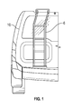
- FIG. 1 is a rear elevation view showing a ladder interconnected to a vehicle
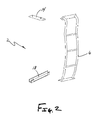
- FIG. 2 is an exploded view of a ladder interconnection system of one embodiment of the present invention
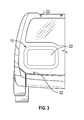
- FIG. 3 is a rear elevation view showing a vehicle before the ladder interconnection system is interconnected to the vehicle;
- FIG. 4 is a partial perspective view showing an upper surface of a vehicle's rear door, wherein a hanger plate has been interconnected thereto;
- FIG. 5 is a detailed side elevation view showing the hanger plate of one embodiment of the present invention interconnected to the rear door;
- FIG. 6 is a partial rear elevation view wherein the rear door is in an open position, and wherein a portion of the hanger plate is visible;
- FIG. 7 is a top perspective view of a hanger plate of one embodiment of the present invention.
- FIG. 8 is a bottom perspective view of the hanger plate showing FIG. 7 ;
- FIG. 9 is a top perspective view of a hanger plate of another embodiment of the present invention.
- FIG. 10 is a bottom perspective view of the hanger plate showing FIG. 9 ;
- FIG. 11 is a top perspective view of a hanger plate of another embodiment of the present invention.
- FIG. 12 is a bottom perspective view of the hanger plate showing FIG. 11 ;
- FIG. 13 is a top perspective view of a hanger plate of another embodiment of the present invention.
- FIG. 14 is a bottom perspective view of the hanger plate showing FIG. 13 ;
- FIG. 15 is a top perspective view of a hanger plate of another embodiment of the present invention.
- FIG. 16 is a bottom perspective view of the hanger plate showing FIG. 15 ;
- FIG. 17 is a rear elevation view showing a ladder interconnected to a vehicle
- FIG. 18 is a partial perspective view showing a clamp interconnecting a lower portion of the ladder to the rear door;
- FIG. 19 is a side detailed view showing the clamp of FIG. 18 interconnecting a lower portion of the ladder to the rear door;
- FIG. 20 is a partial perspective view showing a clamp of another embodiment of the present invention interconnecting a lower portion of the ladder to the rear door;
- FIG. 21 is a side detailed view showing the clamp of FIG. 20 interconnecting a lower portion of the ladder to the rear door.
- FIGS. 1-21 show a ladder interconnection system 2 used to interconnect a ladder 6 to a vehicle 10 .
- the ladder interconnection system 2 of one embodiment of the present invention comprises a hanger plate 14 and a clamp 18 .
- the ladder interconnection system 2 does not require penetrations into the vehicle 10 . Penetrations create a fluid flow path conducive to rusting.
- FIG. 1 shows the ladder 6 interconnected to the vehicle 10 , which commonly used with SUVs as accessing a storage box or vehicle rack is difficult.
- FIG. 2 is an exploded view of the ladder interconnection system 2 of one embodiment of the present invention.
- the ladder 6 is interconnected to the vehicle 10 using the hanger plate 14 and the clamp 18 .
- the hanger plate 14 is adapted for interconnection to an upper portion of the vehicle's rear door. Once the hanger plate 14 is in place, an upper portion of the ladder is interconnected to the hanger plate 14 , which positions the lower portion of the ladder 6 adjacent to the lower edge of the rear door. The lower ladder portion is then secured to the rear door with the clamp 18 . Again, the hanger plate 14 and clamp to not require penetrations into the vehicle. Further, as a ladder 6 , hanger plate 14 , and clamp 18 are interconnected to edges of the rear door, the ladder will travel with the rear door.
- FIG. 3 shows rear vehicle door 20 .
- masking tape 22 to mark the desired location of the ladder.
- masking 22 one can gauge the proper ladder location so the ladder does not obscure lights and the hanger plate will not interfere with the proper functioning of the rear door 20 by contacting the hinge that secures a rear door 20 to the vehicle 10 .
- FIGS. 4-6 illustrate how the hanger plate 14 is interconnected to an upper portion 26 of the rear door 20 .
- tape 30 or foam is added to the lower surface 34 of the hanger plate 14 , which is adapted to interface with the upper portion 26 or edge of the rear door 20 .
- a curled segment 38 is also wrapped around an upper edge 42 of the rear door 20 . The curled segment 38 prevents the hanger plate 14 from being removed upwardly or away from the vehicle. But, as the hanger plate 14 is not bolted or otherwise fastened to the rear door 20 , the ladder can slide laterally along the upper edge 42 .
- the hanger plate is shaped so it fits within a gap 50 between the upper portion 26 of the rear door 20 and the vehicle 10 when the rear door is closed.
- FIG. 5 shows that the hanger plate 14 does not interfere with the gap 50 between the rear door 20 and the vehicle 10 so the rear door 20 can open and close without impacting the hanger plate 14 .
- FIG. 5 also shows a stud 54 extending from the upper surface 58 of the hanger plate 14 designed to receive corresponding holes in an upper portion of the ladder. The ladder is connected to the hanger plate 14 by securing the studs 54 with nuts.
- FIGS. 7 and 8 show a hanger plate 14 of one embodiment of the present invention, which may be used on a Jeep® Cherokee®.
- the hanger plate 14 includes an upper surface 58 with two studs extending therefrom.
- the hanger plate also includes two hooked segments 62 for engagement to the upper edge of the rear door's upper portion.
- the hanger plate includes two corresponding lips 66 for engagement with an outer edge of the rear door's upper surface.
- FIGS. 9 and 10 show a hanger plate 14 of another embodiment of the present invention, which may be used on a Nissan® Element®.
- the hanger plate 14 includes an upper surface 58 with two studs 54 extending therefrom.
- the hanger plate 14 also includes a curled segment 38 for engagement with the upper edge of the rear door.
- FIGS. 11 and 12 show a hanger plate 14 of another embodiment, which may be used on a Toyota® FJ Cruiser®.
- the hanger plate 14 includes an upper surface 58 with two studs 54 extending therefrom.
- the hanger plate 14 also includes a curled segment 38 for engagement with the upper edge of the rear door.
- FIGS. 13 and 14 show a hanger plate 14 of another embodiment of the present invention, which be used on a Toyota® 4Runner®.
- the hanger plate 14 includes an upper surface 58 with two studs 54 extending therefrom.
- Hanger plate 14 also includes a curled segment 38 for engagement with the upper edge of the rear door.
- the hanger plate 14 includes a corresponding lip 66 for engagement with an outer edge of the rear door. Again, the curled portion and lip helps prevent movement of the hanger plate along the vehicle's longitudinal direction.
- FIGS. 15 and 16 show a hanger plate 14 of another embodiment of the present invention, which may be used on a Nissan® Xterra®.
- the hanger plate 14 includes an upper surface 58 with two studs extending therefrom.
- the hanger plate 14 also includes a curled segment 38 for engagement with an upper edge of the rear door.
- the curled segment may include cutouts to accommodate items positioned within the vehicle's rear door, such as bolt heads.
- FIG. 17 illustrates how the ladder 6 of one embodiment of the present invention is interconnected to the hanger plate 14 .
- an upper portion 72 of the ladder having apertures or slots (not shown) is placed over the studs 54 extending from the hanger plate 14 .
- the ladder 6 is then fastened to the hanger plate 14 via washers 76 and nuts 80 . This operation secures the ladder 6 to the rear door 20 , but it can still move laterally along the rear door 20 . This functionality allows the user to ensure the ladder 6 is in the correct position before the clamp is engaged.
- the hanger plates described above include at least one stud that receives and secures the ladder
- the ladder may be hung from the hanger plate in other ways.
- the hanger plate of one embodiment of the present invention includes a peg or pegs that extend from the hanger plate that are received into recesses or slots provided in the ladder upper portion, wherein nuts are not required to secure the ladder.
- the ladder upper portion may include one or more pegs, or other type of protrusion, that fit into cavities, holes, or slots, provided in the hanger plate.
- the ladder upper portion may include a hook or curled portion that fits within a cavity, fits within a hole, or engages onto a complementary hook on the hanger plate.
- the hanger plate may have an extended cavity that receives the complementary extension protruding from the upper ladder portion, or vice versa.
- the interconnection between the upper ladder portion and the hanger plate allows some adjustment of ladder position along the lateral direction of the vehicle.
- the area of engagement between the hanger plate and the upper letter portion may include slotted holes, serrations, or other mechanisms known in the art that allow minute adjustments between interconnected components.
- the method of interconnection between the ladder and a hanger plate may not be relevant in some embodiments of the present invention. This is because the primary purpose of the hanger plate is to allow a ladder to hang therefrom.
- FIGS. 18 and 19 show how the lower portion 84 of the ladder is interconnected to the rear door 20 .
- the rear door 20 is opened to expose the inner surface 88 thereof.
- the clamp 18 which is generally U-shaped member in this embodiment of the present invention, includes a first portion 92 adapted for positioning on an outer surface 96 of the rear door 20 , a second portion 100 , and a third portion 104 adapted for positioning at the inner surface 88 of the rear door 20 .
- tape 30 or foam may mask the area of engagement of the ladder's lower portion 84 to the rear door.
- a set screw 108 is used to tighten the clamp 18 on to the rear door 20 and ladder 6 .
- the set screws 108 may be associated with the pinch plate 112 that contacts the rear door's inner surface 88 .
- FIGS. 20 and 21 show another embodiment of the present invention wherein the clamp 18 has a fourth portion 116 that extends from the first portion 92 .
- the fourth portion 116 may be perpendicular to the first portion 92 and is adapted to further engage the ladder 6 with one or more bolts 120 .
Landscapes
- Engineering & Computer Science (AREA)
- Mechanical Engineering (AREA)
- Manufacturing & Machinery (AREA)
- Chemical & Material Sciences (AREA)
- Combustion & Propulsion (AREA)
- Transportation (AREA)
- Vehicle Step Arrangements And Article Storage (AREA)
- Ladders (AREA)
Abstract
A system is provided for interconnecting a ladder to a vehicle. The system may include a first portion for interconnecting to an upper portion of a vehicle rear door and a second portion for interconnecting to a lower portion of the vehicle rear door. The system provides a ladder interconnection wherein no penetrations are made into the vehicle.
Description
This application claims the benefit of U.S. Provisional Patent Application Ser. No. 62/206,724, filed Aug. 18, 2015, the entirety of which is incorporated by reference herein.
Embodiments of the present invention are generally related to motor vehicle storage racks and ladders.
Vehicle roof racks provide vehicle owners with additional storage options. The storage space roof racks provide allow the area inside the vehicle to be used for additional in-vehicle storage or passenger seating. Often, access to storage racks is difficult, because one must reach upwardly to gain access to the vehicle rack, which is often over six feet from the ground. Standing locations on the outside of the vehicle that would allow one to reach the roof rack are rare or difficult/dangerous to access. For example, some individuals stand on the vehicle's floor or tire to access the storage rack. Unfortunately, the vehicle owner's height, the position of the rack, or the location of the stored items in the rack are often not ideally accessed by standing on the vehicle floor or tire. Thus owners must use a step stool, a ladder, etc. to access the roof rack, which is often not readily available.
To address this issue some vehicle manufacturers have incorporated ladders onto the side or rear of the vehicle. These ladders increase the external envelope of the vehicle and are often unsightly. Existing ladders (or post-market ladders retrofitted onto vehicles) must be bolted to the vehicle, which creates weak points and fluid pathways that facilitate metal oxidation. Further, where the vehicle ladder is interconnected to the rear of the vehicle, rear door operation may be adversely affected.
It is a long felt need to provide an improved ladder that does not require penetrations into the vehicle to install, is aesthetically pleasing, and allows for the vehicle's rear door to function as designed.
It is one aspect of embodiments of the present invention to provide a ladder attachment mechanism wherein no penetrations are made into the vehicle during installation. More specifically, one embodiment of the present invention is a ladder connection mechanism that employs components that interconnect independently to two distinct portions of the vehicle's rear door without affecting the integrity of the door. In operation, one component—a hanger plate—is interconnected to an upper portion of the vehicle's rear door adjacent to a hinge that interconnects the rear door to the vehicle. The hanger plate is fastened in such a way to not interfere with the operation of the hinge and provides a primary ladder retention location.
The ladder attachment system also includes a second component—a clamp—for interconnection to a bottom edge of the rear door. The clamp does not impede the rear door closing. The lower clamp secures a lower portion of the ladder, and with the hanger plate, secures a ladder to the vehicle. The ladder is adapted to move with the rear door as it is opened and closed.
The hanger plate has an added feature in that it helps distribute loads generated by applied weight. More specifically, as many manufacturers employ rear hatchback doors with plastic spoilers or other devices to improve vehicle aesthetics, the hanger plate must provide a sufficient footprint to spread applied loads and reduce pressure when individuals are using the ladder.
It is yet another aspect of embodiments of the present invention to provide a hanger plate and clamp that can be interconnected to various vehicles. That is, the hanger plate may be configured to accommodate vehicles of different manufacturers. Some hanger plates, however, are custom-made to fit certain vehicle models, which will be described in further detail below. Some other contemplated hanger plates include features that allow them to be quickly modified by removing or adding portions thereto so various vehicles can be accommodated with one hanger plate design.
It is still yet another aspect of embodiments of the present invention to provide a ladder attachment system that can be positioned on a driver side or a passenger side of the vehicle. More specifically, depending on the location of a spare tire or the owner's desires, it may be more advantageous to install the ladder on a particular side of the rear door. Some embodiments of the present invention allow users to install the hanger plate on either side of the rear door so it accommodates the hinge on either side of the rear door.
It follows that the embodiments the present invention are easy to install such that if the owner changes their mind, the position of the hanger plate and associated clamp can the selectively altered. Again, one primary aspect of embodiments the present invention is that interconnecting the hanger plate or clamp to the vehicle does not require penetrations be made into the vehicle, which helps increase resale value, and helps decreases the occurrences of oxidation.
It is another aspect of some embodiments of the present invention to provide a system adapted for interconnecting a ladder to a vehicle, wherein the system secures the ladder to the vehicle, the system comprising: a hanger plate adapted for interconnection to an upper portion of a rear door of the vehicle, the hanger plate having an edge with a curled portion adapted for engaging an edge of the upper portion of the rear door, a lower surface adapted for engaging an upper surface associated with the edge of the rear door, and an upper surface having a stud extending therefrom; a clamp adapted for interconnection to a lower portion of a rear door, the clamp having a first portion adapted for positioning adjacent to an inner surface of the rear door, a second surface adapted for positioning adjacent to a lower edge of the rear door, and an outer surface adapted for positioning adjacent to an outer surface of the rear door, the clamp operatively interconnected to a member adapted to selectively engage the rear door, thereby interconnecting the clamp to the rear door; wherein the ladder has an upper portion that interconnects to the stud of the hanger plate; and wherein the ladder has a lower portion adapted for engagement with the rear door and for engagement with the third portion of the clamp.
It is another aspect of some embodiments of the present invention to provide a system adapted for providing access to an upper portion of a vehicle, comprising: a hanger plate adapted for interconnection to an upper portion of a rear door of the vehicle, the hanger plate having an edge with a portion adapted for engaging an edge of the rear door, the hanger plate having a stud extending therefrom; a clamp adapted for interconnection to a lower portion of the rear door, the clamp operatively interconnected to a member adapted to selectively engage the rear door; and a ladder having an upper portion that interconnects to the stud of the hanger plate, and a lower portion interconnected to the clamp.
It is another aspect of some embodiments of the present invention to provide a method of interconnecting a ladder to a vehicle, comprising: providing a hanger plate; providing a clamp; interconnecting the hanger plate to an upper edge of a vehicle rear door, the hanger plate having an edge with a portion that engages the upper edge of the vehicle rear door; interconnecting an upper portion of the ladder to studs extending from the hanger plate, the studs being positioned through apertures in the upper portion of the ladder, wherein the ladder is fastened to the hanger plate by way of a nut received on the stud; and interconnecting the clamp to a lower edge of the vehicle rear door, wherein the clamp has an internal portion positioned on an internal surface of the vehicle rear door and an external portion positioned on an external portion of the rear door, the ladder having a lower portion positioned between the rear door and the external portion, and the clamp having a means for pinching operatively interconnected to the internal portion and adapted for interconnection to the internal surface of the rear door.
It is another aspect of some embodiments of the present invention to provide a hanger plate adapted to secure a ladder to an upper portion of a vehicle rear door, comprising: a plate having a first edge, a second edge, a third edge, and a forth edge, the first edge adapted for interconnection to an inner upper edge of the rear door, the second edge adapted for positioning adjacent to an outer upper edge of the rear door, and the third edge and the fourth edge interconnecting the first edge and the second edge; a curled portion interconnected to the first edge; and at least one stud extending from the plate.
The Summary of the Invention is neither intended nor should it be construed as being representative of the full extent and scope of the present invention. That is, these and other aspects and advantages will be apparent from the disclosure of the invention(s) described herein. Further, the above-described embodiments, aspects, objectives, and configurations are neither complete nor exhaustive. As will be appreciated, other embodiments of the invention are possible using, alone or in combination, one or more of the features set forth above or described below. Moreover, references made herein to “the present invention” or aspects thereof should be understood to mean certain embodiments of the present invention and should not necessarily be construed as limiting all embodiments to a particular description. The present invention is set forth in various levels of detail in the Summary of the Invention as well as in the attached drawings and the Detailed Description of the Invention and no limitation as to the scope of the present invention is intended by either the inclusion or non-inclusion of elements, components, etc. in this Summary of the Invention. Additional aspects of the present invention will become more readily apparent from the Detail Description, particularly when taken together with the drawings.
The accompanying drawings, which are incorporated in and constitute a part of the specification, illustrate embodiments of the invention and together with the general description of the invention given above and the detailed description of the drawings given below, serve to explain the principles of these inventions.
To assist in the understanding of one embodiment of the present invention the following list of components and associated numbering found in the drawings is provided herein:
-
- 2 Ladder interconnection system
- 6 Ladder
- 10 Vehicle
- 14 Hanger plate
- 18 Clamp
- 20 Rear vehicle door
- 22 Masking tape
- 26 Upper portion
- 30 Tape
- 34 Lower surface
- 38 Curled segment
- 42 Upper edge
- 46 Hinge
- 50 Gap
- 54 Stud
- 58 Upper surface
- 62 Hooked segment
- 66 Lip
- 72 Ladder upper portion
- 76 Washer
- 80 Nut
- 84 Ladder lower portion
- 88 Inner surface
- 92 First portion
- 96 Outer surface
- 100 Second portion
- 104 Third portion
- 108 Set screw
- 112 Pinch plate
- 116 Fourth portion
- 120 Bolt
It should be understood that the drawings are not necessarily to scale. In certain instances, details that are not necessary for an understanding of the invention or that render other details difficult to perceive may have been omitted. It should be understood, of course, that the invention is not necessarily limited to the particular embodiments illustrated herein.
Although the hanger plates described above include at least one stud that receives and secures the ladder, those of ordinary skill in the art will appreciate that the ladder may be hung from the hanger plate in other ways. For example, the hanger plate of one embodiment of the present invention includes a peg or pegs that extend from the hanger plate that are received into recesses or slots provided in the ladder upper portion, wherein nuts are not required to secure the ladder. Alternatively, the ladder upper portion may include one or more pegs, or other type of protrusion, that fit into cavities, holes, or slots, provided in the hanger plate. The ladder upper portion may include a hook or curled portion that fits within a cavity, fits within a hole, or engages onto a complementary hook on the hanger plate. The hanger plate may have an extended cavity that receives the complementary extension protruding from the upper ladder portion, or vice versa. In some embodiments, the interconnection between the upper ladder portion and the hanger plate allows some adjustment of ladder position along the lateral direction of the vehicle. For example, the area of engagement between the hanger plate and the upper letter portion may include slotted holes, serrations, or other mechanisms known in the art that allow minute adjustments between interconnected components. Stated in general, one of skill in the art should appreciate upon review of this disclosure that the method of interconnection between the ladder and a hanger plate may not be relevant in some embodiments of the present invention. This is because the primary purpose of the hanger plate is to allow a ladder to hang therefrom.
While various embodiments of the present invention have been described in detail, it is apparent that modifications and alterations of those embodiments will occur to those skilled in the art. It is to be expressly understood that such modifications and alterations are within the scope and spirit of the present invention, as set forth in the following claims. Further, it is to be understood that the invention(s) described herein is not limited in its application to the details of construction and the arrangement of components set forth in the preceding description or illustrated in the drawings. The invention is capable of other embodiments and of being practiced or of being carried out in various ways. Also, it is to be understood that the phraseology and terminology used herein is for the purpose of description and should not be regarded as limiting. The use of “including,” “comprising,” or “having” and variations thereof herein is meant to encompass the items listed thereafter and equivalents thereof as well as additional items.
Claims (15)
1. A system for interconnecting a ladder to a vehicle, wherein said system secures the ladder to the vehicle, said system comprising:
a one-piece integral hanger plate adapted for interconnection to an upper portion of a rear door of the vehicle, said one-piece integral hanger plate having:
a first long edge;
a curled portion extending from the first long edge and adapted for engaging an upper edge of the upper portion of the rear door;
a lower surface adapted for engaging an exterior surface of the rear door;
an upper surface positioned in opposing relationship to the lower surface; and
a stud extending from the upper surface;
a first spacer selectively interconnected to the lower surface of said one-piece integral hanger plate;
a one-piece integral clamp adapted for interconnection to a lower portion of the rear door, said one-piece integral clamp having a first portion adapted for positioning adjacent to an inner surface of the rear door and including an aperture adapted to receive a threaded fastener, a second portion adapted for positioning adjacent to a lower edge of the rear door, and a third portion adapted for positioning adjacent to the exterior surface of the rear door;
a pinch plate adapted to selectively engage the inner surface of the rear door; and
said ladder having an upper portion that interconnects to said stud of said one-piece integral hanger plate and a lower portion including a first member and a second member, wherein the first member extends from a first rail to a second rail of said ladder, and wherein the second member extends from a long edge of the first member, the second member adapted for engagement with the rear door and for engagement with said third portion of said one-piece integral clamp.
2. The system of claim 1 , further comprising a second spacer to be positioned between the rear door and said second member of said lower portion of said ladder.
3. The system of claim 1 , wherein said curled portion extends below said lower surface of said one-piece integral hanger plate.
4. The system of claim 1 , wherein said one-piece integral hanger plate and said one-piece integral clamp are configured to interconnect to the vehicle without penetrating the vehicle.
5. The system of claim 1 , wherein said pinch plate has a body that is generally planar, and wherein said threaded fastener positioned in the aperture of said first portion of said one-piece integral clamp is oriented approximately perpendicular to said generally planar body of said pinch plate.
6. The system of claim 1 , wherein said one-piece integral clamp includes a fourth portion extending approximately perpendicularly from said third portion, said fourth portion interconnectable to said first member of said ladder.
7. The system of claim 1 , wherein said one-piece integral hanger plate includes:
said first long edge;
a second long edge positioned in opposing relationship to said first long edge;
a first narrow edge;
a second narrow edge positioned in opposing relationship to said first narrow edge, wherein said first and second narrow edges are positioned between said first and second long edges; and
said curled portion extending from said first long edge, wherein said curled portion extends along at least a portion of a length of said first long edge.
8. The system of claim 1 , wherein said one-piece integral hanger plate further comprises:
a second edge, a third edge, and a fourth edge, said third edge positioned in opposing relationship to said first long edge, and said second and fourth edges interconnecting said first long edge and said third edge, wherein said curled portion extends at least 50% of the distance between said second edge to said fourth edge.
9. The system of claim 1 , wherein said upper surface of said one-piece integral hanger plate is generally planar.
10. The system of claim 1 , wherein said upper portion of said ladder comprises:
a third member which extends from said first rail to said second rail of said ladder; and
a fourth member extending from said third member and oriented transverse to said first and second rails, said fourth member configured to interconnect said ladder to said stud of said one-piece integral hanger plate.
11. The system of claim 1 , wherein said one-piece integral hanger plate further comprises a second stud extending from the upper surface.
12. The system of claim 11 , wherein said second stud is oriented approximately parallel to said stud.
13. The system of claim 1 , wherein said stud is oriented approximately perpendicular to a rung of said ladder when said upper portion of said ladder is interconnected to said stud.
14. The system of claim 1 , wherein said stud only extends upwardly from the upper surface of the one-piece integral hanger plate.
15. The system of claim 1 , wherein said first spacer includes a foam.
Priority Applications (3)
Application Number | Priority Date | Filing Date | Title |
---|---|---|---|
US14/881,979 US10030446B2 (en) | 2015-08-18 | 2015-10-13 | Vehicle ladder attachment mechanism |
US16/040,797 US10738532B2 (en) | 2015-08-18 | 2018-07-20 | Vehicle ladder attachment mechanism |
US16/984,973 US12024949B2 (en) | 2015-08-18 | 2020-08-04 | Vehicle ladder attachment mechanism |
Applications Claiming Priority (2)
Application Number | Priority Date | Filing Date | Title |
---|---|---|---|
US201562206724P | 2015-08-18 | 2015-08-18 | |
US14/881,979 US10030446B2 (en) | 2015-08-18 | 2015-10-13 | Vehicle ladder attachment mechanism |
Related Child Applications (1)
Application Number | Title | Priority Date | Filing Date |
---|---|---|---|
US16/040,797 Continuation US10738532B2 (en) | 2015-08-18 | 2018-07-20 | Vehicle ladder attachment mechanism |
Publications (2)
Publication Number | Publication Date |
---|---|
US20170050571A1 US20170050571A1 (en) | 2017-02-23 |
US10030446B2 true US10030446B2 (en) | 2018-07-24 |
Family
ID=58157597
Family Applications (3)
Application Number | Title | Priority Date | Filing Date |
---|---|---|---|
US14/881,979 Active US10030446B2 (en) | 2015-08-18 | 2015-10-13 | Vehicle ladder attachment mechanism |
US16/040,797 Active 2035-10-19 US10738532B2 (en) | 2015-08-18 | 2018-07-20 | Vehicle ladder attachment mechanism |
US16/984,973 Active 2037-11-20 US12024949B2 (en) | 2015-08-18 | 2020-08-04 | Vehicle ladder attachment mechanism |
Family Applications After (2)
Application Number | Title | Priority Date | Filing Date |
---|---|---|---|
US16/040,797 Active 2035-10-19 US10738532B2 (en) | 2015-08-18 | 2018-07-20 | Vehicle ladder attachment mechanism |
US16/984,973 Active 2037-11-20 US12024949B2 (en) | 2015-08-18 | 2020-08-04 | Vehicle ladder attachment mechanism |
Country Status (1)
Country | Link |
---|---|
US (3) | US10030446B2 (en) |
Cited By (8)
Publication number | Priority date | Publication date | Assignee | Title |
---|---|---|---|---|
USD906546S1 (en) | 2016-12-30 | 2020-12-29 | Intelligent Designs 2000 Corp. | Vehicle ladder |
US10927599B2 (en) | 2018-12-21 | 2021-02-23 | Timothy Nakari | Roof rack side ladder |
US11142131B2 (en) | 2019-05-15 | 2021-10-12 | Bestop Aluminess, Llc | Modular roof rack system |
US20220073004A1 (en) * | 2020-09-08 | 2022-03-10 | Ford Global Technologies, Llc | Combined vehicle climbing ladder and recovery board |
US20220134954A1 (en) * | 2020-10-30 | 2022-05-05 | Nissan North America, Inc. | Vehicle ladder |
US20220134955A1 (en) * | 2020-10-30 | 2022-05-05 | Nissan North America, Inc. | Vehicle ladder |
RU219693U1 (en) * | 2023-03-10 | 2023-08-01 | Акционерное общество "Рузаевский завод химического машиностроения" (АО "Рузхиммаш") | The body of a railway car for the transportation and storage of goods |
US12024949B2 (en) | 2015-08-18 | 2024-07-02 | Intelligent Designs 2000 Corp. | Vehicle ladder attachment mechanism |
Families Citing this family (6)
Publication number | Priority date | Publication date | Assignee | Title |
---|---|---|---|---|
US20180170272A1 (en) * | 2016-12-19 | 2018-06-21 | Mike Bleazard | Ladder mounting system |
USD812777S1 (en) * | 2017-04-10 | 2018-03-13 | Volvo Lastvagnar Ab | Ladder |
USD832760S1 (en) * | 2017-05-18 | 2018-11-06 | Roambuilt LLC | Vehicle ladder |
USD845853S1 (en) * | 2018-04-04 | 2019-04-16 | Roambuilt LLC | Vehicle ladder |
US20220136326A1 (en) * | 2020-10-30 | 2022-05-05 | Nissan North America, Inc. | Vehicle ladder |
WO2022150658A1 (en) * | 2021-01-07 | 2022-07-14 | Dickman John | Ladder spreader |
Citations (65)
Publication number | Priority date | Publication date | Assignee | Title |
---|---|---|---|---|
US2227873A (en) * | 1939-01-23 | 1941-01-07 | Universal Railway Devices Comp | Running board |
US2419065A (en) * | 1946-02-01 | 1947-04-15 | Victor M Fowler | Ladder brace |
US2485413A (en) * | 1945-03-06 | 1949-10-18 | Allen R Ross | Ladder |
US2947555A (en) * | 1954-03-15 | 1960-08-02 | Olsen Charles | Scaffold ladder clamp |
US3058607A (en) * | 1960-03-11 | 1962-10-16 | James A Kiley Company | Ladder racks |
US3387754A (en) * | 1967-06-21 | 1968-06-11 | Barry L. Sinkey | Spare tire and wheel carrier |
US3498410A (en) * | 1968-10-24 | 1970-03-03 | Mayfair Eng Co | Boat ladder |
US3603431A (en) * | 1969-12-15 | 1971-09-07 | Alfred E Nameche | Ladder and support bracket therefor |
US4239139A (en) * | 1979-02-05 | 1980-12-16 | Bott John Anthony | Sliding tie down vehicle luggage carrier |
US4249683A (en) * | 1980-01-14 | 1981-02-10 | Park John R | Combination ladder and spare tire carrier |
US4312620A (en) * | 1979-11-06 | 1982-01-26 | Muschalek Jr Ben E | Spare tire rack |
US4431082A (en) * | 1981-12-30 | 1984-02-14 | Bott John Anthony | Vehicle ladder |
US4716988A (en) | 1986-08-06 | 1988-01-05 | Top Line Manufacturing Inc. | Ladder step construction for use with recreational vehicles and boats |
US4825975A (en) * | 1988-06-17 | 1989-05-02 | Gregg Symes | Clamping device & mechanics stand for attaching to bumper of motor vehicle |
US4831808A (en) | 1987-10-05 | 1989-05-23 | Wynar Roger N | Self-adjusting wallboard clips |
USD309560S (en) | 1987-10-02 | 1990-07-31 | State of Nebraska, Department of Roads | Adjustable mailbox mounting platform |
US4947961A (en) * | 1989-11-28 | 1990-08-14 | Frank Dudley | Step for attachment to a wheel or bumper |
US5039119A (en) * | 1989-12-29 | 1991-08-13 | Milo Baughman | Retractable stairs for vehicles |
US5131780A (en) * | 1990-03-19 | 1992-07-21 | Grrreat Creations, Inc. | C-clamp |
US5228739A (en) * | 1992-06-08 | 1993-07-20 | Grrreat Creations, Inc. | Truck cap clamp |
USD346355S (en) | 1992-03-13 | 1994-04-26 | Knaack Manufacturing Company | Ladder rack support |
USD346994S (en) | 1992-07-30 | 1994-05-17 | Knaack Manufacturing Company | Ladder rack support |
USD359134S (en) | 1993-09-07 | 1995-06-06 | Toews Thomas R | Flatbed ladder |
USD392178S (en) | 1996-07-03 | 1998-03-17 | Yazaki Industrial Chemical Co. Ltd. | Partition locking metal attachment for wire gauze |
US5765902A (en) * | 1995-11-17 | 1998-06-16 | Grrreat Creations, Inc. | Clamping device |
USD410374S (en) | 1998-09-15 | 1999-06-01 | John Meurer | Tool support |
US6003633A (en) | 1995-04-05 | 1999-12-21 | Robert G. Rolson | Portable truck or trailer ladder assembly |
USD423328S (en) | 1998-09-04 | 2000-04-25 | Gratnell's Limited | Bracket |
US6116378A (en) | 1998-12-09 | 2000-09-12 | Barrow; Sherman Dean | Universal, compact, truck tailgate ladder with support arms |
USD442289S1 (en) | 2000-07-18 | 2001-05-15 | Theodore Ziaylek, Jr. | Vertical ladder movable to an inclined position |
US6231093B1 (en) * | 1999-02-02 | 2001-05-15 | Ron D. Storer | Push bar mounting system |
US6270301B1 (en) * | 2000-07-18 | 2001-08-07 | Keith A. Dunlop | Mounting apparatus for front wall of pick-up truck cargo box |
US6409275B1 (en) * | 2000-05-02 | 2002-06-25 | The Heil Company | Frame attachment for vehicle |
US20030020253A1 (en) * | 1998-12-31 | 2003-01-30 | Booth Engineering Pty Ltd | Guard railing arrangement for tankers |
US6565048B1 (en) * | 1999-08-03 | 2003-05-20 | Thomas & Betts International, Inc. | Cable support bracket assembly |
USD479884S1 (en) | 2002-01-16 | 2003-09-23 | The Berryman 1996 Trust | Truck ladder |
USD490163S1 (en) | 2003-01-03 | 2004-05-18 | Glenn Thurston | Ladder construction |
US6739349B2 (en) | 2002-06-11 | 2004-05-25 | Westfaliasurge, Inc. | Bulk milk tank with adjustable ladder |
US20050082326A1 (en) * | 2003-03-17 | 2005-04-21 | Paul Badillo | Multi-purpose storage rack for a sport utility vehicle |
US20050098595A1 (en) | 2003-11-11 | 2005-05-12 | Smith Robert F. | Clamp assembly for securing a ladder to a vehicle rack |
USD512783S1 (en) | 2003-03-17 | 2005-12-13 | Intelligent Designs 2000 Corp. | Vehicle ladder |
US7025712B2 (en) * | 2002-09-05 | 2006-04-11 | Marco Parrilla | Suspended squat rack |
US20060108179A1 (en) | 2004-11-19 | 2006-05-25 | Joseph Sieb | Portable vehicle ladder system and method |
US20060124394A1 (en) * | 2003-05-01 | 2006-06-15 | Bracken Vincent J C | Ladder clamp |
US20060191967A1 (en) * | 2003-11-11 | 2006-08-31 | Nordman Corporation Of Nc | Clamp assembly for securing a ladder to a vehicle rack |
USD538734S1 (en) | 2005-07-29 | 2007-03-20 | Fenderliminators, Inc. | Motorcycle bracket for mounting license plates and turn signal lights |
US7244090B2 (en) * | 2003-10-17 | 2007-07-17 | Tactical & Rescue Gear, Ltd. | Storage rack for a vehicle |
USD547641S1 (en) | 2005-07-22 | 2007-07-31 | Michael Jueneman | Fastener |
US7249927B2 (en) * | 2003-10-17 | 2007-07-31 | Tactical & Rescue Gear, Ltd. | Storage rack for a vehicle |
USD549838S1 (en) | 2006-05-22 | 2007-08-28 | Intelligent Designs 2000 Corp. | Vehicle ladder |
US20080277199A1 (en) * | 2007-05-07 | 2008-11-13 | Castonguay Lionel F | Ladder |
USD601719S1 (en) | 2009-06-03 | 2009-10-06 | Gibson Carl F | Ladder |
US7789359B2 (en) * | 2007-04-24 | 2010-09-07 | Panduit Corp. | Auxiliary cable bracket |
US7874966B2 (en) * | 2008-09-03 | 2011-01-25 | Marco Parrilla | Barbell holder |
US20110101057A1 (en) * | 2009-08-26 | 2011-05-05 | Intelligent Design 2000 Corp. | Convertible Vehicle Storage Rack |
USD657054S1 (en) * | 2011-05-05 | 2012-04-03 | Bacon Glenn S | Medical bracket and clamp |
US8157229B2 (en) * | 2007-03-21 | 2012-04-17 | Brian Palermo | Vehicle bed raingutter bracket for rack system |
US8261880B1 (en) * | 2007-03-09 | 2012-09-11 | Hop Daryl J | Step ladder apparatus |
US8585107B2 (en) * | 2011-08-31 | 2013-11-19 | Iddea California, Llc | Push bumper and mounting system |
US8602162B2 (en) * | 2011-04-18 | 2013-12-10 | King Fahd University Of Petroleum And Minerals | Safety ladder |
USD710030S1 (en) | 2012-12-31 | 2014-07-29 | Treeline Treestands, LLC | Irregular-shaped ladder for a tree stand |
US20150252618A1 (en) * | 2012-09-18 | 2015-09-10 | Avraham Y. Levi | Door mounted ladder for cargo vans |
US9345923B2 (en) * | 2014-08-14 | 2016-05-24 | Adam Haggard | Weight training apparatus and method of using |
USD759841S1 (en) | 2015-08-11 | 2016-06-21 | Intelligent Designs 2000 Corporation | Vehicle ladder |
USD770962S1 (en) | 2015-09-30 | 2016-11-08 | Intelligent Designs 2000 Corp. | Vehicle rack ladder bracket |
Family Cites Families (84)
Publication number | Priority date | Publication date | Assignee | Title |
---|---|---|---|---|
US563085A (en) * | 1896-06-30 | Railway-track | ||
US1003044A (en) | 1908-05-09 | 1911-09-12 | Westinghouse Electric & Mfg Co | Circuit-interrupter. |
US1443391A (en) * | 1922-06-15 | 1923-01-30 | Joseph J Soldat | Curtain stretcher |
US2322798A (en) * | 1941-09-29 | 1943-06-29 | Fischer Joseph | Automobile accessory |
US2398306A (en) * | 1945-01-30 | 1946-04-09 | John H Hermanson | Safety clamp for scaffolds |
US2481120A (en) * | 1946-12-10 | 1949-09-06 | Harry N Juel | Railway journal box |
US2693386A (en) * | 1954-04-20 | 1954-11-02 | Renfroe & Sons J C | Beam clamp |
US3028929A (en) * | 1960-03-08 | 1962-04-10 | Howard L Chubbs | Ladder attachment |
GB1050005A (en) * | 1963-10-02 | |||
US3544955A (en) * | 1967-03-28 | 1970-12-01 | Raul Heres Ruiz | Cable connector |
US3431005A (en) * | 1967-08-25 | 1969-03-04 | Marvin J Priefert | Vertical bumper guard attachment |
US3601294A (en) * | 1969-04-18 | 1971-08-24 | Donald J Gjesdahl | Car top ski rack |
US3604676A (en) * | 1969-10-21 | 1971-09-14 | Thomas & Betts Corp | Grounding and clamping device |
US3965525A (en) * | 1975-05-09 | 1976-06-29 | Brissette Edward C | Shag rake attachment for upright vacuum cleaner |
US4151895A (en) | 1977-12-02 | 1979-05-01 | Rasada Frank M Jr | Recreational vehicle ladder |
US4320816A (en) * | 1980-10-21 | 1982-03-23 | Callahan Phyllis M | Window perch |
US5121960A (en) * | 1984-09-14 | 1992-06-16 | Wheatley Donald G | Rail attachment system for tonneau cover |
US5058652A (en) * | 1984-09-14 | 1991-10-22 | Wheatley Donald G | Tonneau cover |
US4691907A (en) * | 1985-03-06 | 1987-09-08 | Yang Tai Her | C-clamp structure |
US4613120A (en) * | 1985-05-28 | 1986-09-23 | Kozar John J | D-clamp vise |
US4953820A (en) * | 1985-06-20 | 1990-09-04 | Universal Consolidated Methods, Inc. | Lamp with retaining ring |
US4901963A (en) * | 1985-06-20 | 1990-02-20 | Universal Consolidated Methods, Inc. | Adjustable clamp |
US4719989A (en) * | 1987-06-26 | 1988-01-19 | Step-On Inc. | Boat boarding ladders having a stowage feature |
US5275458A (en) * | 1991-03-29 | 1994-01-04 | Custom Form Manufacturing, Inc. | Tonneau cover assembly |
US5310238A (en) * | 1993-01-29 | 1994-05-10 | Wheatley Donald G | Mounting apparatus for a truck bed |
US5573228A (en) * | 1995-01-10 | 1996-11-12 | Chestnut; William J. | Miter clamp |
US5636893A (en) * | 1995-04-17 | 1997-06-10 | Wheatley; Donald E. | Folding hard panel tonneau cover with rail attachment |
US5788315A (en) * | 1996-06-03 | 1998-08-04 | Design Automotive Group, Inc. | Tonneau cover apparatus |
USD389450S (en) * | 1996-07-30 | 1998-01-20 | Wilson Dallas W | Accessory support clamp for trucks |
US5975618A (en) * | 1996-10-24 | 1999-11-02 | Saddleman, Inc. | Vehicle tonneau cover clamp |
US6023800A (en) * | 1997-05-09 | 2000-02-15 | Midmark Corporation | Removable accessory for a surgical table |
US5931521A (en) * | 1997-05-29 | 1999-08-03 | Kooiker; John | Folding cover for pickup truck bed |
AU3082199A (en) * | 1998-03-12 | 1999-09-27 | Falcon Enterprises, Llc | Mounting bracket and raptor perch guard |
US6442805B2 (en) * | 1999-03-26 | 2002-09-03 | Joel W. Pfister | Attachment system for configured slots |
US6350089B1 (en) * | 1999-03-31 | 2002-02-26 | Terence V. Tekavec | Pickup truck bed portable tie-down apparatus |
US6338520B2 (en) * | 1999-09-02 | 2002-01-15 | The Budd Company | Tonneau cover and attachment assembly |
US6256844B1 (en) * | 1999-11-03 | 2001-07-10 | Donald G. Wheatley | Tie-down anchor assembly |
US6422635B1 (en) * | 2000-01-20 | 2002-07-23 | Steffens Enterprises, Inc. | Folding cargo bay cover for pickup truck |
US6378654B1 (en) * | 2000-07-18 | 2002-04-30 | Theodore Ziaylek, Jr. | Ladder pivotally attached to a generally vertically extending surface |
US6725623B1 (en) * | 2000-11-15 | 2004-04-27 | Action Manufacturing, Llc | Standing seam metal roof wind uplift prevention bar |
US7017238B2 (en) * | 2002-08-29 | 2006-03-28 | Gen-Probe Incorporated | Clamp |
IL151819A0 (en) | 2002-09-19 | 2003-04-10 | Asaf Metal 1997 Ltd | Tailgate ladder |
US6905153B2 (en) * | 2002-11-11 | 2005-06-14 | Pro-Gard Industries, L.P. | Push bumper |
US7055787B2 (en) * | 2003-01-27 | 2006-06-06 | Christopher Todd Cross | Sheet material clamp |
US6932193B2 (en) | 2003-08-22 | 2005-08-23 | George R Tombarello | Boat bow access ladder for trailer |
US6948588B1 (en) * | 2004-03-31 | 2005-09-27 | Chustak Daniel A | Track and hinge for a boat ladder |
US7066299B1 (en) * | 2004-04-08 | 2006-06-27 | Jeffrey John Fleming | Portable ladder suspension apparatus or a portable ladder for suspension or the combination thereof |
US7537264B2 (en) * | 2006-09-29 | 2009-05-26 | Israel Maimin | Pick-up truck box cover |
US20080250614A1 (en) * | 2007-04-11 | 2008-10-16 | Zante Anthony A | Flexible clamp |
US8235340B2 (en) * | 2007-05-31 | 2012-08-07 | Carnevali Jeffrey D | Portable aviation clamp |
US7704104B2 (en) * | 2007-06-27 | 2010-04-27 | Duley Wayne C | Bus bar system, method, and kit |
US7819225B2 (en) * | 2007-08-20 | 2010-10-26 | Smith Christopher L | Ice ladder |
US20090183443A1 (en) * | 2008-01-21 | 2009-07-23 | Osborn Eric C | Universal structural attachment for seismic brace |
US7946643B2 (en) * | 2008-03-13 | 2011-05-24 | Scott Getschel | Tonneau cover |
US7988464B2 (en) * | 2008-04-09 | 2011-08-02 | Panduit Corp. | Beam clamp |
US8714495B2 (en) * | 2009-05-27 | 2014-05-06 | Philip Allen Myers | Building strut system |
US8857771B2 (en) * | 2009-09-18 | 2014-10-14 | Randy J. Streetman | Conduit attachment device for use with a trapeze |
US20110132252A1 (en) * | 2009-12-09 | 2011-06-09 | Alex R. Kaye and Frances Kaye Trust | Portable boat casting deck |
US20120096691A1 (en) * | 2010-10-26 | 2012-04-26 | Abraham Sacks | Selective angle clamp apparatus and systems |
US8782985B2 (en) * | 2012-03-01 | 2014-07-22 | Usg Interiors, Llc | Splice clip for ceiling grid systems |
US9248784B2 (en) * | 2012-04-30 | 2016-02-02 | Yakima Products, Inc. | Truck crossbar attachment |
USD694607S1 (en) * | 2013-03-14 | 2013-12-03 | Canica Design Inc. | Saw vise |
US9945179B1 (en) * | 2013-07-11 | 2018-04-17 | David K. Joldersma | Removable step ladder for recreational vehicle |
US9527712B1 (en) * | 2014-07-16 | 2016-12-27 | John R. Pigg | Shooting house and hoisting system for tree |
US10017235B2 (en) * | 2014-12-05 | 2018-07-10 | James A. Pappas | Retractable boat extension |
US10030446B2 (en) | 2015-08-18 | 2018-07-24 | Intelligent Designs 2000 Corp. | Vehicle ladder attachment mechanism |
US10760298B2 (en) * | 2015-09-24 | 2020-09-01 | Fonda Crandall | Fence brace system adapted for use with cylindrical fence posts |
DE102015222346A1 (en) * | 2015-11-12 | 2017-05-18 | Siemens Aktiengesellschaft | mounting clamp |
US10359212B2 (en) * | 2016-05-11 | 2019-07-23 | Nation Wide Products Llc | Apparatus and method for securing an air conditioning unit in a window |
US10858887B2 (en) | 2016-08-11 | 2020-12-08 | Bobo Ladders Llc | Boat or recreational vehicle ladder apparatus |
CN106314099A (en) * | 2016-10-21 | 2017-01-11 | 徐恩立 | Truck cover system |
USD882119S1 (en) | 2016-12-30 | 2020-04-21 | Intelligent Designs 2000 Corp. | Vehicle ladder |
US10112542B2 (en) | 2017-01-13 | 2018-10-30 | Altec Industries, Inc. | Deploying vehicle ladder |
US10046724B2 (en) * | 2017-01-17 | 2018-08-14 | Ford Global Technologies, Llc | Method and apparatus for attaching police push bars |
USD812777S1 (en) | 2017-04-10 | 2018-03-13 | Volvo Lastvagnar Ab | Ladder |
USD822851S1 (en) | 2017-05-16 | 2018-07-10 | Furion Fabrication, Llc | Ladder |
USD832760S1 (en) | 2017-05-18 | 2018-11-06 | Roambuilt LLC | Vehicle ladder |
USD845853S1 (en) | 2018-04-04 | 2019-04-16 | Roambuilt LLC | Vehicle ladder |
US20190351832A1 (en) * | 2018-05-17 | 2019-11-21 | Lippert Components, Inc. | Adjustable stair assembly |
US10746209B2 (en) * | 2018-08-14 | 2020-08-18 | Retrax Holdings, Llc | Adjustable clamp |
CA3055844A1 (en) * | 2019-09-18 | 2021-03-18 | Wade J. Mcallister | Temporary exterior noise interruption pollution wall |
US11162518B1 (en) * | 2020-02-28 | 2021-11-02 | Preston R. Macy | Rail clamp assembly |
AU2021239839A1 (en) * | 2020-03-16 | 2022-10-06 | Rmh Tech Llc | Mounting device for a metal roof |
US11839048B2 (en) * | 2020-09-29 | 2023-12-05 | Super Micro Computer, Inc. | Pole mount system for facilitating installation of heavy telecommunications equipment |
-
2015
- 2015-10-13 US US14/881,979 patent/US10030446B2/en active Active
-
2018
- 2018-07-20 US US16/040,797 patent/US10738532B2/en active Active
-
2020
- 2020-08-04 US US16/984,973 patent/US12024949B2/en active Active
Patent Citations (66)
Publication number | Priority date | Publication date | Assignee | Title |
---|---|---|---|---|
US2227873A (en) * | 1939-01-23 | 1941-01-07 | Universal Railway Devices Comp | Running board |
US2485413A (en) * | 1945-03-06 | 1949-10-18 | Allen R Ross | Ladder |
US2419065A (en) * | 1946-02-01 | 1947-04-15 | Victor M Fowler | Ladder brace |
US2947555A (en) * | 1954-03-15 | 1960-08-02 | Olsen Charles | Scaffold ladder clamp |
US3058607A (en) * | 1960-03-11 | 1962-10-16 | James A Kiley Company | Ladder racks |
US3387754A (en) * | 1967-06-21 | 1968-06-11 | Barry L. Sinkey | Spare tire and wheel carrier |
US3498410A (en) * | 1968-10-24 | 1970-03-03 | Mayfair Eng Co | Boat ladder |
US3603431A (en) * | 1969-12-15 | 1971-09-07 | Alfred E Nameche | Ladder and support bracket therefor |
US4239139A (en) * | 1979-02-05 | 1980-12-16 | Bott John Anthony | Sliding tie down vehicle luggage carrier |
US4312620A (en) * | 1979-11-06 | 1982-01-26 | Muschalek Jr Ben E | Spare tire rack |
US4249683A (en) * | 1980-01-14 | 1981-02-10 | Park John R | Combination ladder and spare tire carrier |
US4431082A (en) * | 1981-12-30 | 1984-02-14 | Bott John Anthony | Vehicle ladder |
US4716988A (en) | 1986-08-06 | 1988-01-05 | Top Line Manufacturing Inc. | Ladder step construction for use with recreational vehicles and boats |
USD309560S (en) | 1987-10-02 | 1990-07-31 | State of Nebraska, Department of Roads | Adjustable mailbox mounting platform |
US4831808A (en) | 1987-10-05 | 1989-05-23 | Wynar Roger N | Self-adjusting wallboard clips |
US4825975A (en) * | 1988-06-17 | 1989-05-02 | Gregg Symes | Clamping device & mechanics stand for attaching to bumper of motor vehicle |
US4947961A (en) * | 1989-11-28 | 1990-08-14 | Frank Dudley | Step for attachment to a wheel or bumper |
US5039119A (en) * | 1989-12-29 | 1991-08-13 | Milo Baughman | Retractable stairs for vehicles |
US5131780A (en) * | 1990-03-19 | 1992-07-21 | Grrreat Creations, Inc. | C-clamp |
USD346355S (en) | 1992-03-13 | 1994-04-26 | Knaack Manufacturing Company | Ladder rack support |
US5228739A (en) * | 1992-06-08 | 1993-07-20 | Grrreat Creations, Inc. | Truck cap clamp |
USD346994S (en) | 1992-07-30 | 1994-05-17 | Knaack Manufacturing Company | Ladder rack support |
USD359134S (en) | 1993-09-07 | 1995-06-06 | Toews Thomas R | Flatbed ladder |
US6003633A (en) | 1995-04-05 | 1999-12-21 | Robert G. Rolson | Portable truck or trailer ladder assembly |
US5765902A (en) * | 1995-11-17 | 1998-06-16 | Grrreat Creations, Inc. | Clamping device |
USD392178S (en) | 1996-07-03 | 1998-03-17 | Yazaki Industrial Chemical Co. Ltd. | Partition locking metal attachment for wire gauze |
USD423328S (en) | 1998-09-04 | 2000-04-25 | Gratnell's Limited | Bracket |
USD410374S (en) | 1998-09-15 | 1999-06-01 | John Meurer | Tool support |
US6116378A (en) | 1998-12-09 | 2000-09-12 | Barrow; Sherman Dean | Universal, compact, truck tailgate ladder with support arms |
US20030020253A1 (en) * | 1998-12-31 | 2003-01-30 | Booth Engineering Pty Ltd | Guard railing arrangement for tankers |
US6231093B1 (en) * | 1999-02-02 | 2001-05-15 | Ron D. Storer | Push bar mounting system |
US6565048B1 (en) * | 1999-08-03 | 2003-05-20 | Thomas & Betts International, Inc. | Cable support bracket assembly |
US6409275B1 (en) * | 2000-05-02 | 2002-06-25 | The Heil Company | Frame attachment for vehicle |
USD442289S1 (en) | 2000-07-18 | 2001-05-15 | Theodore Ziaylek, Jr. | Vertical ladder movable to an inclined position |
US6270301B1 (en) * | 2000-07-18 | 2001-08-07 | Keith A. Dunlop | Mounting apparatus for front wall of pick-up truck cargo box |
USD479884S1 (en) | 2002-01-16 | 2003-09-23 | The Berryman 1996 Trust | Truck ladder |
US6739349B2 (en) | 2002-06-11 | 2004-05-25 | Westfaliasurge, Inc. | Bulk milk tank with adjustable ladder |
US7025712B2 (en) * | 2002-09-05 | 2006-04-11 | Marco Parrilla | Suspended squat rack |
USD490163S1 (en) | 2003-01-03 | 2004-05-18 | Glenn Thurston | Ladder construction |
US20050082326A1 (en) * | 2003-03-17 | 2005-04-21 | Paul Badillo | Multi-purpose storage rack for a sport utility vehicle |
USD512783S1 (en) | 2003-03-17 | 2005-12-13 | Intelligent Designs 2000 Corp. | Vehicle ladder |
US20060124394A1 (en) * | 2003-05-01 | 2006-06-15 | Bracken Vincent J C | Ladder clamp |
US7244090B2 (en) * | 2003-10-17 | 2007-07-17 | Tactical & Rescue Gear, Ltd. | Storage rack for a vehicle |
US7249927B2 (en) * | 2003-10-17 | 2007-07-31 | Tactical & Rescue Gear, Ltd. | Storage rack for a vehicle |
US20050098595A1 (en) | 2003-11-11 | 2005-05-12 | Smith Robert F. | Clamp assembly for securing a ladder to a vehicle rack |
US20060191967A1 (en) * | 2003-11-11 | 2006-08-31 | Nordman Corporation Of Nc | Clamp assembly for securing a ladder to a vehicle rack |
US20060108179A1 (en) | 2004-11-19 | 2006-05-25 | Joseph Sieb | Portable vehicle ladder system and method |
USD547641S1 (en) | 2005-07-22 | 2007-07-31 | Michael Jueneman | Fastener |
USD538734S1 (en) | 2005-07-29 | 2007-03-20 | Fenderliminators, Inc. | Motorcycle bracket for mounting license plates and turn signal lights |
USD549838S1 (en) | 2006-05-22 | 2007-08-28 | Intelligent Designs 2000 Corp. | Vehicle ladder |
US8261880B1 (en) * | 2007-03-09 | 2012-09-11 | Hop Daryl J | Step ladder apparatus |
US8157229B2 (en) * | 2007-03-21 | 2012-04-17 | Brian Palermo | Vehicle bed raingutter bracket for rack system |
US7789359B2 (en) * | 2007-04-24 | 2010-09-07 | Panduit Corp. | Auxiliary cable bracket |
US20080277199A1 (en) * | 2007-05-07 | 2008-11-13 | Castonguay Lionel F | Ladder |
US7874966B2 (en) * | 2008-09-03 | 2011-01-25 | Marco Parrilla | Barbell holder |
USD601719S1 (en) | 2009-06-03 | 2009-10-06 | Gibson Carl F | Ladder |
US8496146B2 (en) | 2009-08-26 | 2013-07-30 | Intelligent Designs 2000 Corp. | Convertible vehicle storage rack |
US20110101057A1 (en) * | 2009-08-26 | 2011-05-05 | Intelligent Design 2000 Corp. | Convertible Vehicle Storage Rack |
US8602162B2 (en) * | 2011-04-18 | 2013-12-10 | King Fahd University Of Petroleum And Minerals | Safety ladder |
USD657054S1 (en) * | 2011-05-05 | 2012-04-03 | Bacon Glenn S | Medical bracket and clamp |
US8585107B2 (en) * | 2011-08-31 | 2013-11-19 | Iddea California, Llc | Push bumper and mounting system |
US20150252618A1 (en) * | 2012-09-18 | 2015-09-10 | Avraham Y. Levi | Door mounted ladder for cargo vans |
USD710030S1 (en) | 2012-12-31 | 2014-07-29 | Treeline Treestands, LLC | Irregular-shaped ladder for a tree stand |
US9345923B2 (en) * | 2014-08-14 | 2016-05-24 | Adam Haggard | Weight training apparatus and method of using |
USD759841S1 (en) | 2015-08-11 | 2016-06-21 | Intelligent Designs 2000 Corporation | Vehicle ladder |
USD770962S1 (en) | 2015-09-30 | 2016-11-08 | Intelligent Designs 2000 Corp. | Vehicle rack ladder bracket |
Non-Patent Citations (2)
Title |
---|
"FJ Ladder," BajaRack Adventure Equipment, 2 pages, first sale estimated in 2011 [retrieved from: http://www.bajarack.com/ladder]. |
U.S. Appl. No. 29/589,364, filed Dec. 30, 2016, Badillo. |
Cited By (11)
Publication number | Priority date | Publication date | Assignee | Title |
---|---|---|---|---|
US12024949B2 (en) | 2015-08-18 | 2024-07-02 | Intelligent Designs 2000 Corp. | Vehicle ladder attachment mechanism |
USD906546S1 (en) | 2016-12-30 | 2020-12-29 | Intelligent Designs 2000 Corp. | Vehicle ladder |
US10927599B2 (en) | 2018-12-21 | 2021-02-23 | Timothy Nakari | Roof rack side ladder |
US11142131B2 (en) | 2019-05-15 | 2021-10-12 | Bestop Aluminess, Llc | Modular roof rack system |
US20220073004A1 (en) * | 2020-09-08 | 2022-03-10 | Ford Global Technologies, Llc | Combined vehicle climbing ladder and recovery board |
US20220134954A1 (en) * | 2020-10-30 | 2022-05-05 | Nissan North America, Inc. | Vehicle ladder |
US20220134955A1 (en) * | 2020-10-30 | 2022-05-05 | Nissan North America, Inc. | Vehicle ladder |
US11981289B2 (en) * | 2020-10-30 | 2024-05-14 | Nissan North a, nc. | Vehicle ladder |
RU219693U1 (en) * | 2023-03-10 | 2023-08-01 | Акционерное общество "Рузаевский завод химического машиностроения" (АО "Рузхиммаш") | The body of a railway car for the transportation and storage of goods |
RU219789U1 (en) * | 2023-03-10 | 2023-08-07 | Акционерное общество "Рузаевский завод химического машиностроения" (АО "Рузхиммаш") | The body of a railway car for the transportation and storage of goods |
RU219906U1 (en) * | 2023-03-10 | 2023-08-11 | Акционерное общество "Рузаевский завод химического машиностроения" (АО "Рузхиммаш") | The body of a railway car for the transportation and storage of goods |
Also Published As
Publication number | Publication date |
---|---|
US12024949B2 (en) | 2024-07-02 |
US20170050571A1 (en) | 2017-02-23 |
US20180328109A1 (en) | 2018-11-15 |
US20200362631A1 (en) | 2020-11-19 |
US10738532B2 (en) | 2020-08-11 |
Similar Documents
Publication | Publication Date | Title |
---|---|---|
US12024949B2 (en) | Vehicle ladder attachment mechanism | |
US7555816B2 (en) | Toolbox latch and hinge apparatus and method | |
US9726206B2 (en) | Method of attaching an object to a panel with an adjustable tower stud assembly | |
US7628440B2 (en) | Cargo space arrangement | |
US6290441B1 (en) | Stake pocket tie down | |
US8020921B2 (en) | Door trim panel having temporary support and pivot members and method of installing the door trim panel | |
US11752945B2 (en) | Roof rack system for a vehicle | |
US9120426B1 (en) | Wheelhouse cladding step | |
US11981289B2 (en) | Vehicle ladder | |
US3140891A (en) | Rocker panel and body sill moulding | |
US6776450B2 (en) | Attachment structure of slide rail cover to vehicle body | |
US10221600B2 (en) | Vehicle body system | |
US9079625B1 (en) | Tailgate enclosure apparatus | |
US20170120963A1 (en) | Glide Mechanism for an Automotive Storage Container | |
US8733826B1 (en) | Truck bed panel attached to door hinge mounting plate | |
US9751468B1 (en) | Vehicle rack bracket | |
US10519994B2 (en) | Mounting arrangement | |
KR100600190B1 (en) | Center roller structure of sliding door for automobile | |
JP6531557B2 (en) | Fender step structure | |
KR200481413Y1 (en) | Tool box for installing on the roof of the truck have gutter | |
CN108327638B (en) | Exposed hinge of integrated footboard and have its vehicle | |
US20220325580A1 (en) | Detachable ladder and wall mount | |
JP7028041B2 (en) | Roof rack mounting structure | |
JPH06191439A (en) | Rear structure of automobile | |
US20050274757A1 (en) | Vehicular rail mounting system |
Legal Events
Date | Code | Title | Description |
---|---|---|---|
AS | Assignment |
Owner name: INTELLIGENT DESIGNS 2000 CORP., COLORADO Free format text: ASSIGNMENT OF ASSIGNORS INTEREST;ASSIGNOR:BADILLO, PAUL;REEL/FRAME:038514/0355 Effective date: 20160506 |
|
STCF | Information on status: patent grant |
Free format text: PATENTED CASE |
|
MAFP | Maintenance fee payment |
Free format text: PAYMENT OF MAINTENANCE FEE, 4TH YR, SMALL ENTITY (ORIGINAL EVENT CODE: M2551); ENTITY STATUS OF PATENT OWNER: SMALL ENTITY Year of fee payment: 4 |