US10027922B2 - Imaging apparatus for displaying a specific scene while continuously photographing, image playback method, and non-transitory computer-readable storage medium - Google Patents
Imaging apparatus for displaying a specific scene while continuously photographing, image playback method, and non-transitory computer-readable storage medium Download PDFInfo
- Publication number
- US10027922B2 US10027922B2 US15/064,470 US201615064470A US10027922B2 US 10027922 B2 US10027922 B2 US 10027922B2 US 201615064470 A US201615064470 A US 201615064470A US 10027922 B2 US10027922 B2 US 10027922B2
- Authority
- US
- United States
- Prior art keywords
- images
- user
- playback
- specific scene
- image
- Prior art date
- Legal status (The legal status is an assumption and is not a legal conclusion. Google has not performed a legal analysis and makes no representation as to the accuracy of the status listed.)
- Active, expires
Links
Images


Classifications
-
- H—ELECTRICITY
- H04—ELECTRIC COMMUNICATION TECHNIQUE
- H04N—PICTORIAL COMMUNICATION, e.g. TELEVISION
- H04N5/00—Details of television systems
- H04N5/76—Television signal recording
- H04N5/765—Interface circuits between an apparatus for recording and another apparatus
- H04N5/77—Interface circuits between an apparatus for recording and another apparatus between a recording apparatus and a television camera
- H04N5/772—Interface circuits between an apparatus for recording and another apparatus between a recording apparatus and a television camera the recording apparatus and the television camera being placed in the same enclosure
-
- H—ELECTRICITY
- H04—ELECTRIC COMMUNICATION TECHNIQUE
- H04N—PICTORIAL COMMUNICATION, e.g. TELEVISION
- H04N5/00—Details of television systems
- H04N5/76—Television signal recording
- H04N5/91—Television signal processing therefor
- H04N5/93—Regeneration of the television signal or of selected parts thereof
-
- G—PHYSICS
- G06—COMPUTING OR CALCULATING; COUNTING
- G06F—ELECTRIC DIGITAL DATA PROCESSING
- G06F1/00—Details not covered by groups G06F3/00 - G06F13/00 and G06F21/00
- G06F1/16—Constructional details or arrangements
- G06F1/1613—Constructional details or arrangements for portable computers
- G06F1/163—Wearable computers, e.g. on a belt
-
- G—PHYSICS
- G06—COMPUTING OR CALCULATING; COUNTING
- G06F—ELECTRIC DIGITAL DATA PROCESSING
- G06F3/00—Input arrangements for transferring data to be processed into a form capable of being handled by the computer; Output arrangements for transferring data from processing unit to output unit, e.g. interface arrangements
- G06F3/01—Input arrangements or combined input and output arrangements for interaction between user and computer
- G06F3/017—Gesture based interaction, e.g. based on a set of recognized hand gestures
-
- G—PHYSICS
- G06—COMPUTING OR CALCULATING; COUNTING
- G06F—ELECTRIC DIGITAL DATA PROCESSING
- G06F3/00—Input arrangements for transferring data to be processed into a form capable of being handled by the computer; Output arrangements for transferring data from processing unit to output unit, e.g. interface arrangements
- G06F3/01—Input arrangements or combined input and output arrangements for interaction between user and computer
- G06F3/03—Arrangements for converting the position or the displacement of a member into a coded form
-
- H—ELECTRICITY
- H04—ELECTRIC COMMUNICATION TECHNIQUE
- H04N—PICTORIAL COMMUNICATION, e.g. TELEVISION
- H04N23/00—Cameras or camera modules comprising electronic image sensors; Control thereof
- H04N23/60—Control of cameras or camera modules
-
- H04N5/232—
-
- H—ELECTRICITY
- H04—ELECTRIC COMMUNICATION TECHNIQUE
- H04N—PICTORIAL COMMUNICATION, e.g. TELEVISION
- H04N5/00—Details of television systems
- H04N5/76—Television signal recording
- H04N5/78—Television signal recording using magnetic recording
- H04N5/782—Television signal recording using magnetic recording on tape
- H04N5/783—Adaptations for reproducing at a rate different from the recording rate
Definitions
- the present invention relates to an imaging apparatus for controlling display of images continuously captured by an imaging means, and a corresponding image playback method and non-transitory computer-readable storage medium.
- timing at which a desired scene appears is unknown when a moving image is captured by an imaging apparatus such as a digital still camera or video camera
- the user performs an operation of giving an instruction to start moving image recording before the desired scene appears, whereby a recording operation is started.
- the user performs an operation of giving an instruction to stop the moving image recording operation. Accordingly, in the playback of the recorded moving image, the user has to view not only the desired scene but also images previous and subsequent thereto.
- Japanese Patent Application Laid-Open (Kokai) Publication No. 05-15628 discloses a technology in which, when a specific scene (timing when a golf club passes a lowermost point) is detected during image capturing at a high frame rate, recorded images including images captured before and after the detection timing of the specific scene are replayed at a slow speed.
- an imaging apparatus comprising: an imaging section which includes an image sensor; a display section which includes a display; a storage section which includes a memory; and a control section which includes a processor, wherein the control section performs control of (i) setting a specific scene in advance, (ii) sequentially storing images continuously captured by the imaging section in the storage section as a storing operation, (iii) specifying images corresponding to the specific scene from among a plurality of images stored in the storage section when a predetermined motion of a user is detected during the storing operation, and (iv) displaying the specified images corresponding to the specific scene on the display section while continuing the storing operation, wherein the control section, when there is an image of a segment corresponding to the specific scene completely stored before a timing of detection of the predetermined motion of the user during the storing operation, starts playback of the image of the segment, and wherein the control section, when there is no image of a segment corresponding to the specific scene completely stored
- an image playback method for an imaging apparatus comprising: setting a specific scene in advance; sequentially storing continuously captured images as a storing operation; specifying images corresponding to the specific scene from among a plurality of stored images when a predetermined motion of a user is detected during the storing operation; displaying the specified images corresponding to the specific scene while continuing the storing operation; when there is an image of a segment corresponding to the specific scene completely stored before a timing of detection of the predetermined motion of the user during the storing operation, starting playback of the image of the segment; and when there is no image of a segment corresponding to the specific scene completely stored before the timing of the detection of the predetermined motion of the user during the storing operation, waiting for completion of storage of an image of a segment corresponding to the specific scene which is being stored, and then starting playback of the image of the segment.
- a non-transitory computer-readable storage medium having a program stored thereon that is executable by a computer in an imaging apparatus to perform functions comprising: setting a specific scene in advance; sequentially storing continuously captured images as a storing operation; specifying images corresponding to the specific scene from among a plurality of stored images when a predetermined motion of a user is detected during the storing operation; displaying the specified images corresponding to the specific scene while continuing the storing operation; when there is an image of a segment corresponding to the specific scene completely stored before a timing of detection of the predetermined motion of the user during the storing operation, starting playback of the image of the segment; and when there is no image of a segment corresponding to the specific scene completely stored before the timing of the detection of the predetermined motion of the user during the storing operation, waiting for completion of storage of an image of a segment corresponding to the specific scene which is being stored, and then starting playback of the image of the segment.
- FIG. 1 is a block diagram showing basic components of a wearable camera, in which the present invention has been applied as an imaging apparatus;
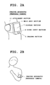
- FIG. 2A is an external view of the wearable camera worn on an arm of a user
- FIG. 2B is a diagram depicting a state where the user is viewing a screen of the wearable camera worn on the arm;
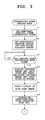
- FIG. 3 is a flowchart of an operation of a main control section 1 (operation of a characteristic portion of a first embodiment) that is started when a current mode is switched to an imaging mode;
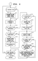
- FIG. 4 is a flowchart of an operation subsequent to FIG. 3 ;
- FIG. 5 is a flowchart of an operation of a playback control section 8 that is started in accordance with playback instruction timing from the main control section 1 ;
- FIG. 6A is a diagram for describing various methods for specifying and replaying playback target images, in which playback instruction timing has been detected after photographing and recording of an interesting scene;
- FIG. 6B is a diagram for describing various methods for specifying and replaying playback target images, in which playback instruction timing has been detected during photographing and recording of an interesting scene;
- FIG. 7A and FIG. 7B are diagrams each depicting a display screen of a display section 7 where the interruption playback of an interesting scene is performed;
- FIG. 8A and FIG. 8B are diagrams for describing a modification example of the first embodiment
- FIG. 9A is a diagram for describing a playback speed change table RS provided in a storage section 3 in a second embodiment
- FIG. 9B is a diagram showing angle ranges.
- FIG. 10 is a flowchart outlining an operation of an imaging apparatus (operation of a characteristic portion of the second embodiment) that is started when a current mode is switched to an imaging mode in the second embodiment.
- FIG. 1 is a block diagram showing basic components of a digital camera, in which the present invention has been applied as an imaging apparatus.
- This imaging apparatus is a wearable camera (for example, an arm-mount camera) capable of photographing with it being worn on a predetermined body part, and has an imaging function capable of capturing a moving image or still image of a photographic subject with high definition, a clock function for clocking a current time and timer time, and the like.
- the interruption playback function is a function of reading out, at predetermined timing, images (captured images or recorded images) of a specific scene (user-desired interesting scene) specified in advance by a user operation from among moving images captured during moving image capturing and recording, and automatically performing interruption playback (playback during image capturing and recording or playback without stopping image capturing and recording).
- the interruption playback function will be described later in detail.
- a main control section 1 in FIG. 1 operates by power supplied from a power supply section (secondary battery) 2 , and controls the entire operation of the imaging apparatus (wearable camera) by following various programs stored in a storage section 3 .
- the main control section 1 is provided with a processor (Central Processing Unit (CPU)), a memory, and the like not shown in the drawing.
- the storage section 3 is structured to have, for example, a ROM (Read Only Memory), a flash memory, and the like, and includes a program memory 3 A where a program and various applications for achieving the present embodiment are stored, a work memory 3 B for temporarily storing a flag and the like, a buffer memory (scene buffer) 3 C having a predetermined capacity for sequentially storing images captured by the imaging function, and the like.
- the buffer memory 3 C is a temporary storage memory constituted, for example, by a ring buffer or the like, and records an image of a desired scene specified by a user (interesting scene) in an identifiable manner so that its recording position can be clearly indicated.
- the main control section 1 overwrites and updates the oldest image with the latest image, and thereby records a predetermined amount of images.
- the storage section 3 may be structured to include a removable portable memory (recording medium) such as an SD (Secure Digital) card or an IC (Integrated Circuit) card, or may be structured to include, although not shown, a storage area on a predetermined server apparatus side in a case where the camera is connected to a network by a communication function.
- a removable portable memory such as an SD (Secure Digital) card or an IC (Integrated Circuit) card
- an operation section 4 includes various operation keys such as a power supply key for turning power on or off, an operation mode switching key, and an imaging condition setting key.
- the main control section 1 performs imaging processing, imaging condition setting processing, or the like.
- captured images are acquired, displayed as a live view image, and sequentially recorded in the buffer memory 3 C.
- images of a specific scene (interesting scene) specified in advance are read out from the buffer memory 3 C at predetermined timing and subjected to interruption playback.
- an imaging section 5 in FIG. 1 is capable of capturing an image (moving image and still image) of a photographic subject with high definition by forming a subject image from an optical lens at an image sensor such as a CCD (Charge-Coupled Device) or CMOS (Complementary Metal Oxide Semiconductor), and has an imaging lens, the image sensor, various sensors, and an imaging control circuit (such as an analog processing section and a digital processing section).
- a sound input section 6 in FIG. 1 is structured to have a microphone where surrounding sound is inputted. Sound inputted from the sound input section 6 is recorded in a sound memory (omitted in the drawing) in association with an image captured by the imaging section 5 .
- a display and a display control circuit for example, a liquid-crystal display device is used, and has a display screen that serves as a monitor screen (live view screen) for displaying images captured by the imaging section 5 (live view image) in real time or serves as a replay screen for replaying captured images (stored images).
- a playback control section 8 When an interruption playback instruction is received from the main control section 1 during image capturing and recording in the imaging mode, a playback control section 8 performs processing of specifying an interesting scene of a playback target and reading out images of the interesting scene from the buffer memory 3 C for interruption playback on the display screen of the display section 7 .
- This playback control section 8 is provided with a processor (Central Processing Unit (CPU)), a memory, and the like not shown.
- the dedicated playback control section 8 is provided in addition to the main control section 1 .
- the present invention is not limited thereto, and the main control section 1 may perform the operation of the playback control section 8 while performing the operation of image capturing and recording in parallel (time-division).
- FIG. 2A and FIG. 2B are external views of the imaging apparatus (wearable camera) worn on an arm of the user.
- a main body section 11 where the imaging section 5 and the display section 7 are arranged is provided on the front surface, and an attachment section 12 including a belt for wearing the imaging apparatus on an arm is also provided, as shown in FIG. 2A .
- an attachment section 12 including a belt for wearing the imaging apparatus on an arm is also provided, as shown in FIG. 2A .
- FIG. 2B shows a state where the user is gazing into the display screen (monitor screen) of the display section 6 in the imaging mode by folding his or her arm inward to view the display section 6 .
- the main control section 1 analyses images captured during image capturing and recording and, if the face of the user set in advance is shown therein, detects the position of the user's eyeball or pupil to judge whether the sight line of the user is oriented to the display screen.
- the imaging section 5 and the display section 6 are arranged on the same plane of the main body section 11 , when the user orients his or her face diagonally downward so as to gaze into the display screen as shown in the drawing, the face of the user comes within the viewing angle of the imaging section 5 . Therefore, by identifying the position of the eyeball or pupil, the direction of the sight line of the user can be detected.
- the main control section 1 Based on the analysis of captured images, when judged during image capturing and recording that the sight line of the user is oriented to the display screen, the main control section 1 provides the timing of this judgment to the playback control section 8 as playback instruction timing.
- the playback control section 8 specifies images (interesting scene) of the playback target based on the timing signal, and reads out the images of the interesting scene from the buffer memory 3 C for interruption playback on the display screen of the display section 6 .
- slow playback is performed at a speed slower than (for example, one quarter of) the speed of the operation of sequentially recording the captured images. Note that, in some cases below, images of a specific scene (interesting scene) are referred to simply as a specific scene (interesting scene).
- FIG. 3 and FIG. 4 are flowcharts outlining the operation of the characteristic portion of the present embodiment from among all of the operations of the main control section 1 . After exiting these flows of FIG. 3 and FIG. 4 , the main control section 1 returns to the main flow (omitted in the drawings) of the overall operation.
- FIG. 3 and FIG. 4 are flowcharts of an operation of the main control section 1 (operation of the characteristic portion of the present embodiment) which is started when a current mode is switched to the imaging mode.
- the main control section 1 performs processing for setting a desired scene specified by the user (specific scene or interesting scene) (Step A 1 in FIG. 3 ).
- the main control section 1 sets the scene information in the work memory 3 B.
- the main control section 1 when at least one piece of information is inputted by a user operation as scene information, the main control section 1 performs processing of setting the scene information in the work memory 3 B.
- the main control section 1 performs processing of setting the selected specifying method in the work memory 3 B (Step A 2 ). Note that this specifying method will be described later in detail.
- the main control section 1 starts processing of acquiring images (moving image) captured by the imaging section 5 and sequentially recording the images in the buffer memory 3 C (Step A 4 ).
- the main control section 1 also starts processing of acquiring sound information from the sound input section 6 and sequentially recording the sound information in the sound memory.
- the main control section 1 starts processing of displaying the captured images on the display screen (monitor screen) of the display section 7 as a live view image (Step A 5 ).
- Step A 6 After performing processing of initializing a flag (hereinafter referred to as a detection flag, which is omitted in the drawing) indicating that the interesting scene is being detected (setting off the flag) (Step A 6 ), the main control section 1 returns to Step A 7 of FIG. 4 , and judges whether the buffer memory 3 C is full (in a full state) during the image capturing and recording.
- the main control section 1 controls a writing operation in the buffer memory 3 C to overwrite and update the oldest image with the latest image (Step A 8 ).
- the main control section 1 acquires captured images, and analyzes the captured images and input sounds to judge whether the interesting scene is present (Step A 9 ). For example, while sequentially analyzing the captured images, the main control section 1 detects a differential change of a background portion, detects the face of the photographic subject, detects the motion of a moving body, and detects input sounds. Then, by comparing the detection result and the interesting scene set at Step A 1 described above, the main control section 1 detects the interesting scene based on a judgment as to whether both are similar in characteristic to each other, such as whether a set specific subject (such as a person) is shown in the images or whether the motion of the photographic subject is the specific motion.
- a set specific subject such as a person
- Step A 9 when the interesting scene is not detected (NO at Step A 10 ), the main control section 1 judges whether the detection flag is ON (Step A 15 ). Initially, the detection flag is OFF by the initialization (NO at Step A 15 ), and therefore the main control section 1 proceeds to processing of detecting the sight line of the user (Step A 18 ). In the sight line detection processing, the main control section 1 identifies the position of an eyeball or pupil from the face of the user shown in the viewing angle of the imaging section 5 and, based on the position of the eyeball or pupil, detects the direction of the sight line of the user.
- the main control section 1 judges whether the sight line of the user is oriented to the display screen (Step A 19 ).
- the main control section 1 proceeds to Step A 14 , and judges whether an instruction to end the moving image capturing has been provided by a user operation.
- the main control section 1 returns to Step A 7 to judge whether the buffer memory 3 C is in a full state, and repeats the above-described operation until the interesting scene is detected at Step A 10 .
- Step A 9 when the interesting scene is detected (YES at Step A 10 ), the main control section 1 judges whether the detection flag is OFF (Step A 11 ).
- the main control section 1 proceeds to Step A 12 , records position information for identifying the start position of the interesting scene in the buffer memory 3 C, and notifies the user that the start of the interesting scene has been detected by flashing of the entire display screen.
- the notifying method is not limited to this, and the notification may be made by emitting alarm sound, light, vibration, or the like. Then, after performing processing of turning the detection flag ON (Step A 13 ) for indicating that the interesting scene is being detected, the main control section 1 proceeds to processing of detecting the sight line of the user (Step A 18 ).
- Step A 18 when judged that the sight line is not oriented to the display screen (NO at Step A 19 ), the main control section 1 returns to Step A 7 on condition that an instruction to end the image capturing has not been given (NO at Step A 14 ). Subsequently, as a result of the processing of detecting the interesting scene (Step A 9 ), if the interesting scene is being detected (YES at Step A 10 ), the detection flag stays ON (NO at Step A 11 ), and therefore the main control section 1 proceeds to the sight line detection processing (Step A 18 ).
- the main control section 1 proceeds to the sight line detection processing (Step A 18 ), and continuously monitors for the sight line of the user even after the detection of the interesting scene.
- Step A 9 when the interesting scene is not detected (NO at Step A 10 ), the main control section 1 judges whether the detection flag is ON as described above (Step A 15 ).
- the detection flag is ON (YES at Step A 15 )
- the main control section 1 performs processing of recording position information for identifying the end position of the scene in the buffer memory 3 C (Step A 16 ).
- the main control section 1 proceeds to the sight line detection processing (Step A 18 ), and continuously monitors for the sight line of the user even after the end of the interesting scene.
- Step A 15 After the detection of the start of the interesting scene, if the interesting scene ends without the sight line of the user being oriented to the display screen (YES at Step A 15 and NO at Step A 19 ), the main control section 1 returns from Step A 14 to Step A 7 . Then, if the interesting scene is not detected thereafter (NO at Step A 10 ), the main control section 1 proceeds to Step A 15 . In this case, since the detection flag has been turned OFF at the time of the detection of the end of the interesting scene (NO at Step A 15 ), the main control section 1 proceeds to the sight line detection processing (Step A 18 ), continuously monitors for the sight line of the user even after the end of the interesting scene.
- Step A 14 captured images are sequentially recorded in the buffer memory 3 C. Also, position information for identifying the start position and end position of the interesting scene every time the interesting scene is detected is recorded in the buffer memory 3 C such that it is identifiable. In this embodiment, writing in the buffer memory 3 C is performed by overwriting and updating the oldest image with the latest image. Therefore, a new moving image of a certain amount is recorded in the buffer memory 3 C.
- the main control section 1 provides a timing signal for instructing the playback control section 8 to perform playback (Step A 21 ) on condition that the interesting scene has been recorded in the buffer memory 3 C, that is, at least the position information indicating the start position of the interesting scene has been recorded (YES at Step A 20 ).
- the main control section 1 provides the playback control section 8 with information indicating whether the interesting scene is being detected. Then, the main control section 1 proceeds to Step A 14 described above, and returns to Step A 7 on condition that an instruction to end the image capturing has not been given (NO at Step A 14 ).
- FIG. 5 is a flowchart of an operation of the playback control section 8 which is started in accordance with playback instruction timing provided from the main control section 1 .
- the playback control section 8 judges whether image capturing and recording are being performed (Step B 1 ). If the timing when the sight line of the user is oriented to the display screen is not timing during image capturing and recording (NO at Step B 1 ), the playback control section 8 selects the method set at Step A 2 of FIG. 3 from specifying methods (A) and (B) described later (Step B 2 ). When judged that image capturing and recording are being performed (YES at Step B 1 ), the playback control section 8 selects the method set at Step A 2 of FIG.
- Step B 3 from specifying methods (C), (D), and (E) described later. Then, by following the selected method, the playback control section 8 reads out images of the specified playback target from the buffer memory 3 C (Step B 4 ), and starts interruption playback (Step B 5 ).
- FIG. 6A and FIG. 6B are diagrams for describing various methods for performing interruption playback by specifying an image of a playback target.
- FIG. 6A shows a case where playback instruction timing has been detected after the image capturing and recording of interesting scenes.
- interesting scenes (1), (2), and (3) have been sequentially recorded in the buffer memory 3 C.
- “t” represents time axis, and playback instruction timing has been received after the recording of the latest interesting scene (3).
- method (A) When playback instruction timing is received after the image capturing and recording of interesting scenes as described above, one of methods (A) and (B) is selected.
- method (A) an interesting scene recorded immediately before playback instruction timing is specified as a playback target, and replayed at the playback instruction timing.
- method (B) an interesting scene recorded a predetermined time (for example, ten seconds) before playback instruction timing is specified as a playback target, and replayed at the playback instruction timing.
- interesting scene (1) is specified as a playback target and replayed in method (A)
- interesting scenes (2) and (3) are specified as playback targets and replayed in method (B).
- FIG. 6B depicts a case where playback instruction timing has been detected during the image capturing and recording of an interesting scene.
- interesting scenes (1), (2), and (3) have been sequentially recorded in the buffer memory 3 C.
- “t” represents time axis
- playback instruction timing has been received after the recording of the latest interesting scene (3).
- one of methods (C), (D), and (E) is selected.
- method (C) an interesting scene during image capturing and recording is specified as a playback target, and the playback of this interesting scene is started after the completion of the recording.
- method (D) the playback of the interesting scene is started immediately without waiting for the completion of the recording of the interesting scene during the image capturing and recording.
- method (E) another specific scene recorded before the playback instruction timing is specified as a playback target and the playback of this specific scene is started immediately without waiting for the completion of the recording of the above-described interesting scene during the image capturing and recording.
- method (C) interesting scene (3) during image capturing and recording is replayed after the completion of the recording.
- method (D) interesting scene (3) is immediately replayed without waiting for the completion of the recording of interesting scene (3) during the image capturing and recording.
- method (E) another interesting scene (2) different from interesting scene (3) that is being imaged and recorded is immediately replayed without waiting for the completion of the recording of interesting scene (3).
- method (E) is selected, if images of an interesting scene recorded before playback instruction timing during image capturing and recording are present, the playback of these images is started. If such images have not been recorded, image playback is started after the completion of the image capturing and recording of images of an interesting scene that are being recorded. Therefore, even when method (E) is selected, if images of an interesting scene recorded before playback instruction timing are not present in practice, method (E) is switched to method (C).
- FIG. 7A and FIG. 7B are diagrams each depicting a playback screen of the display section 7 where the interruption playback of an interesting scene is performed.
- FIG. 7A shows a case where the entire display screen of the display section 7 has been switched to an interruption playback screen.
- FIG. 7B shows a case where the display screen has been vertically divided into two screen, in which one half area (upper-half area) serves as a live view screen for displaying a live view image, and the other half area (lower-half region) serves as a screen for interruption playback.
- one half area upper-half area
- the other half area lower-half region
- Step B 5 When the interruption playback of the interesting scene specified as a playback target as described above is started (Step B 5 ), the playback control section 8 judges whether or not the playback of the images of the playback target has been performed to the end position (Step B 6 ). When judged that the playback has not been ended (NO at Step B 6 ), the playback control section 8 judges whether or not the sight line of the user is oriented to an area other than the display screen (Step B 8 ). In this case as well, the playback control section 8 identifies the position of an eyeball or pupil of the user from the face of the user, and detects the direction of the sight line of the user based on the position of the eyeball or pupil.
- the playback control section 8 judges that the sight line of the user is no longer oriented to the display screen.
- the playback control section 8 when judged that the sight line of the user is not oriented to an area other than the display screen (NO at Step B 8 ), since the user is continuously viewing the display screen, the playback control section 8 returns to Step B 4 described above.
- the playback control section 8 judges whether or not a predetermined time (for example, five seconds) has elapsed after the change of the direction of the sight line (Step B 9 ). That is, even when the sight line is oriented to an area other than the display screen, it may be only temporary in some cases.
- the playback control section 8 judges whether or not the predetermined time has elapsed after the change of the direction of the sight line and, when judged that the predetermined time has not passed (NO at Step B 9 ), the playback control section 8 returns to Step B 4 described above, and stays in a standby state while repeating the above-described operation until the end of the playback is detected (NO at Step B 6 ) or the predetermined time elapses after the sight line is oriented to an area other than the display screen (YES at Step B 9 ).
- Step B 7 when the end of the playback is detected (YES at Step B 6 ), the playback control section 8 judges whether or not the next playback target is present (Step B 7 ). For example, when there is only one playback target with method (A) in FIG. 6A being selected, if the playback of this interesting scene ends, the playback control section 8 judges at Step B 7 that “the next playback target is not present”, and therefore proceeds to Step B 10 to perform playback end processing so as to return the display screen of the display section 7 to a normal live view screen. When there are two playback targets with method (B) in FIG. 6A being selected, the playback control section 8 judges at Step B 7 that “the next playback target is present” even when the first playback has been ended.
- the playback control section 8 returns to Step B 4 , reads out images of the remaining playback target from the buffer memory 3 C, and starts the playback of these images (Step B 5 ).
- the playback control section 8 proceeds to Step B 10 , performs playback end processing, and returns the display screen of the display section 7 to the normal live view screen.
- this interesting scene is stored such that it is differentiated (by adding information regarding the start position and the end position). Then, the interesting scene is identified and read out for playback. As a result of this configuration, interesting scenes can be appropriately extracted and replayed.
- a period during which image capturing and recording is performed is an operation period where an operation of displaying captured images as a live view image is performed, and an interesting scene detected during this operation period is recorded. Accordingly, a live view image can be replayed.
- captured images are replayed at a speed slower than that for sequentially recording these images.
- replayed images can be easily checked.
- the replay position does not catch up with the image capturing and recording position.
- playback is performed by using one of the methods including the method in which, after the recording of an interesting scene which is being captured and recorded is completed, the images of the interesting scene are specified as a playback target and the playback of these images is started; the method where the images of the interesting scene are immediately specified as a playback target and the playback of these images is started before the image capturing and recording is completed; and the method where another interesting scene recorded before the playback instruction timing is immediately specified as a playback target and the playback of the images thereof is started before the image capturing and recording is completed.
- playback can be performed with various methods.
- the playback method can be selected from among the methods including the method in which, after the recording of an interesting scene which is being captured and recorded is completed, the images of the interesting scene are specified as a playback target and the playback of these images is started; the method where the images of the interesting scene are immediately specified as a playback target and the playback of these images is started before the image capturing and recording is completed; and the method where another interesting scene recorded before the playback instruction timing is immediately specified as a playback target and the playback of the images thereof is started before the image capturing and recording is completed, playback can be performed with a method desired by the user.
- timing when the sight line of the user is oriented to the screen is detected as playback instruction timing.
- the user's natural motion motion of trying to view replayed image
- quick playback can be performed.
- interruption playback ends when the sight line of the user is detected to have been oriented toward an area other than the screen.
- interruption playback can be ended by the detection of the user's natural motion (motion of finishing replayed image viewing).
- a notification of the detection and recording is provided.
- the user can orient his or her sight line to the screen in response to the notification.
- At least one piece of information among characteristic information regarding a photographic subject on the screen, motion information regarding the photographic subject, and sound information regarding the photographic subject is inputted and specified by a user operation.
- a user-desired interesting scene can be appropriately specified.
- timing when the sight line of the user is detected to have been oriented to the screen is detected as playback instruction timing.
- timing when the body for example, the face or the upper body
- the end of playback may be detected when the body of the user is detected to have been oriented to an area other than the screen.
- timing when the sight line and the body are detected to have been oriented to the screen may be detected as playback instruction timing.
- the orientation of the body may be detected not only by image analysis but also by using an orientation sensor such as an acceleration sensor mounted in the imaging apparatus.
- images captured by the imaging section 5 are acquired and sequentially recorded in the buffer memory 3 C.
- position information showing the start position and the end position of the scene are recorded.
- only the detected interesting scene may be recorded in the buffer memory 3 C. That is, a configuration may be adopted in which specific scenes are sequentially recorded in the buffer memory 3 C every time an interesting scene is detected.
- timing when the sight line of the user is detected to have been oriented to the screen is detected as playback instruction timing.
- predetermined timing immediately after the detection of an interesting scene or immediately after the recording of an interesting scene in the buffer memory 3 C may be detected as playback instruction timing. That is, the recording of an interesting scene and the playback of the recorded images of this scene may be started immediately after the detection of the start of the interesting scene.
- image capturing and recording and image playback may not be performed at substantially same timing, and timing after a predetermined time (for example, three seconds) may be taken as playback instruction timing.
- the interruption playback of recorded images desired by the user can be performed at appropriate timing without requiring a special operation during image capturing and recording.
- specifying method (B) has been described in which an interesting scene recorded a predetermined time (for example, ten seconds) before playback instruction timing is specified as a playback target and replayed at the playback instruction timing.
- the present invention is not limited to the method where an interesting scene recorded a predetermined time before playback instruction timing is specified as a playback target, and a predetermined number of interesting scenes recorded earlier than playback instruction timing may be specified as playback targets, as shown in FIG. 8A .
- FIG. 8A which is a diagram basically similar to FIG. 6A
- a predetermined number of scenes for example, two scenes
- interesting scenes (2) and (3) recorded earlier than the playback instruction timing are specified as playback targets.
- FIG. 8B in a case where a predetermined number of scenes recorded earlier than playback instruction timing are specified as playback targets, if the number of recorded interesting scenes is small, even an old interesting scene is specified as a playback target. Therefore, among interesting scenes recorded in a predetermined amount of time (for example, twenty seconds), a predetermined number of (two) interesting scenes recorded earlier than playback instruction timing is specified as playback targets. In the example shown in the drawing, only interesting scene (3) has been recorded within the predetermined amount of time (for example, twenty seconds). Therefore, even though the predetermined number is two, only interesting scene (3) is specified as a playback target.
- an interesting scene is detected by analyzing captured images.
- the present invention is not limited to the configuration where an interesting scene is detected by analyzing images.
- various sensors may be used to detect an environmental change or status change, and an interesting scene may be detected based on the environmental change or status change.
- images to be replayed by interruption playback at predetermined timing during image capturing and recording are recorded such that they are overwritten and updated by using temporary storage means with a storage capacity fixed in advance.
- temporary storage means with a storage capacity fixed in advance.
- all captured images may be recorded without limiting the storage capacity in advance.
- a relatively small-capacity and high-speed temporary storage memory such as an internal memory may be used, or a removable low-speed large-capacity memory may be used.
- the sight line of the user is detected to give an instruction for playback.
- a replay instruction may be given by a user operation.
- the timing of giving an instruction to replay an interesting scene is detected during moving image capturing and recording, and interruption playback is performed at the playback instruction timing of detecting the interesting scene.
- the playback speed is changed based on the situation of the user viewing the display screen.
- FIG. 9A is a diagram for explaining a playback speed change table RS included in the storage section 3 in the second embodiment.
- the playback speed change table RS is a table that is referred to when a playback speed is changed based on the situation of the user viewing the display screen in interruption playback during moving image capturing and recording, and has fields of “sight line angle range”, “gaze time”, and “playback speed”.
- “Sight line angle range” indicates an angle range when the face of the user is oriented to the display screen, in which an angle range of the sight line of the user within a range in a direction perpendicular to the display screen (horizontal plane) (within 90 degrees) is indicated. In the example in the drawing, angle ranges of “0 ⁇ 1”, “ ⁇ 1 ⁇ 2”, and “ ⁇ 2 ⁇ 3” are shown.
- 9B shows angle ranges of “0 ⁇ 1”, “ ⁇ 1 ⁇ 2”, and “ ⁇ 2 ⁇ 3”.
- “ ⁇ 1” is 15 degrees
- “ ⁇ 2” is 45 degrees
- “ ⁇ 3” is 90 degrees
- three angle ranges are set, that is, a range not less than 0 degrees and less than 15 degrees, a range not less than 15 degrees and less than 45 degrees, and a range not less than 45 degrees and not more than 90 degrees.
- gaze time a duration in which the face of the user is oriented to the display screen is taken as a gaze time.
- time ranges acquired by dividing time are “0 ⁇ T ⁇ T1”, “T1 ⁇ T ⁇ T2”, and “T2 ⁇ T”. For example, when “T1” is two seconds and “T2” is three seconds, three time ranges are acquired by division, that is, a range not less than 0 seconds and less than two seconds, a range not less than two seconds and less than three seconds, and a range not less than three seconds.
- “Playback speed” indicates a speed of interruption playback.
- V1 is stored in association with “sight line angle range” of “0 ⁇ 1” and “gaze time” of “0 ⁇ T ⁇ T1”
- V2 is stored in association with “ ⁇ 1 ⁇ 2” and “T1 ⁇ T ⁇ T2”
- V3 is stored in association with “ ⁇ 2 ⁇ 3” and “T2 ⁇ T”.
- V1”, “V2”, and “V3” have a relation of V1>V2>V3.
- the playback speed change table RS is set such that the playback speed is slower as “sight line angle range” is larger and “gaze time” is longer.
- the playback speed change table RS can be arbitrarily set by a user operation.
- FIG. 10 is a flowchart outlining an operation (operation of a characteristic portion of the present embodiment) of the imaging apparatus (wearable camera) that is started when a current mode is switched to the imaging mode in the second embodiment.
- the main control section 1 of the imaging apparatus starts processing of acquiring images captured by the imaging section 5 and sequentially recording the images in the buffer memory 3 C (Step C 1 ), and also starts processing of displaying the captured images on the display screen of the display section 7 as a live view image (Step C 2 ).
- the main control section 1 proceeds to processing of detecting the sight line of the user, identifying the position of an eyeball or pupil from the face of the user in the viewing angle of the imaging section 5 , detecting the direction of the sight line of the user based on the position of the eyeball or pupil (Step C 3 ), and judging whether or not the sight line of the user is oriented to the display screen (Step C 4 ).
- the main control section 1 proceeds to Step C 13 , and judges whether or not an instruction to end the moving image capturing has been given by a user operation.
- the main control section 1 When judged that an instruction to end the image capturing has not been given (NO at Step C 13 ), the main control section 1 returns to the sight line detection processing (Step C 3 ), and repeats the above-described operations until the sight line is oriented to the display screen or an instruction to end the moving image capturing is given.
- the main control section 1 detects an angle in a perpendicular direction with respect to the display screen (horizontal plane) based on the direction of the sight line (Step C 5 ), measures a duration in which the sight line is oriented to the display screen, and detects this duration as a gaze time in which the user is continuously viewing the display screen (Step C 6 ). Then, the main control section 1 judges whether playback is being performed (Step C 7 ).
- Step C 7 playback has not been started (NO at Step C 7 ), and therefore the main control section 1 proceeds to Step C 8 , and determines a “playback speed” with reference to the playback speed change table RS based on the sight line angle and the gaze time detected this time (Step C 8 ).
- the main control section 1 reads out a “playback speed” corresponding to the sight line angle and a “playback speed” corresponding to the gaze time, compares both playback speeds, and determines a slower speed as a playback speed. Note that an arbitrary method can be used to determine this playback speed and, for example, an average value between the playback speeds may be calculated.
- the main control section 1 proceeds to Step C 9 , and starts an operation of replaying the recorded moving image in the buffer memory 3 C at the determined “playback speed”.
- the main control section 1 detects at Step C 7 that playback is being performed as described above, and therefore proceeds to Step C 10 to judge whether or not a section range is changed with reference to the playback speed change table RS based on the sight line angle and the gaze time detected this time.
- the main control section 1 judges that the section range is changed.
- the main control section 1 performs processing of reading out a “playback speed” corresponding to the changed section range and changing the playback speed (Step C 11 ).
- the main control section 1 continues the interruption playback with the changed “playback speed” (Step C 12 ).
- the main control section 1 returns to the sight line detection processing (Step C 3 ), and repeats the above-described operation.
- a playback speed is changed based on the situation of the user viewing the display screen, and interruption playback is performed at this changed playback speed.
- the interruption playback of recorded images can be performed appropriately without requiring a special operation during image capturing and recording. Accordingly, for example, when whether or not an image is interesting to the user is judged based on the situation of the user viewing the display screen, if the image is not interesting the user, a playback speed therefor is changed to a relatively high speed and playback is performed at normal speed. If the image is interesting to the user, the playback speed can be changed to a slow speed for slow playback.
- the sight line of the user is oriented to the display screen, the degree of the orientation of the sight line is detected, and a playback speed is changed based on the degree of the sight line.
- a playback speed is changed based on the degree of the sight line.
- interruption playback is performed at a speed slower than that of the operation of sequentially recording captured images. As a result of this configuration, even when recorded images are replayed during image capturing and recording, this playback does not catch up with the image capturing and recording.
- the degree of the orientation of the sight line is detected, that is, the angle of the sight line with respect to the display screen and a duration (gaze time) in which the sight line is continuously oriented to the display screen are detected.
- the situation of the user is not limited to thereto.
- the degree of the orientation of the body for example, the face or upper body
- the angle of the body with respect to the display screen and a duration in which the body is continuously oriented to the display screen may be detected.
- the orientation of the body may be detected not only by image analysis but by using an orientation sensor such as an acceleration sensor.
- the buffer memory 3 C for temporary storage is used.
- a memory that records and stores captured images may be used in place of the buffer memory 3 C.
- the present invention has been applied in a wearable camera as an imaging apparatus.
- the present invention is not limited thereto, and may be applied to a portable compact camera or to a camera-equipped personal computer, a PDA (Personal Digital Assistance), a tablet terminal apparatus, a portable telephone such as a smartphone, an electronic game machine, a music player, and the like.
- PDA Personal Digital Assistance
- tablet terminal apparatus a portable telephone such as a smartphone, an electronic game machine, a music player, and the like.
- the “apparatuses” or the “sections” described in the above-described embodiments are not required to be in a single housing and may be separated into a plurality of housings by function.
- the steps in the above-described flowcharts are not required to be processed in time-series, and may be processed in parallel, or individually and independently.
- all or part of various functions constituted by electronic circuits in each of the above-described embodiments may be achieved by software (causing a program stored in a RAM or ROM to be executed by the CPU). Also, all or part of various functions achieved by software in each of the above-described embodiments may be constituted by an electronic circuit(s).
- An imaging apparatus including:
- an imaging section which includes an image sensor
- a display section which includes a display
- a storage section which includes a memory
- control section which includes a processor
- control section performs control of (i) setting a specific scene in advance, (ii) sequentially storing images continuously captured by the imaging section in the storage section as a storing operation, (iii) specifying images corresponding to the specific scene from among a plurality of images stored in the storage section when a predetermined motion of a user is detected during the storing operation, and (iv) displaying the specified images on the display section while continuing the storing operation.
- control section sequentially stores the images continuously captured by the imaging section in the storage section as moving images, (ii) specifies a moving image of a segment corresponding to the specific scene from among the moving images stored in the storage section when the predetermined motion of the user is detected during storage of the moving images, (iii) replays the specified moving image of the segment while continuing the storage of the moving images. (iv) and displays the specified moving image on the display section.
- control section allows the user to select, as a playback and display method when the moving image of the segment corresponding to the specific scene is being stored at the timing of the detection of the predetermined motion of the user, any one of
- control section when there is no moving image of a segment corresponding to the specific scene completely stored before the detection timing, waits for the completion of the storage of the moving image of the segment corresponding to the specific scene which is being stored, and then starts the playback of the moving image of the segment.
- control section detects the specific scene based on at least one of characteristic information regarding a photographic subject in an image, motion information regarding the photographic subject, and sound information regarding the photographic subject.
Landscapes
- Engineering & Computer Science (AREA)
- Theoretical Computer Science (AREA)
- Multimedia (AREA)
- Signal Processing (AREA)
- General Engineering & Computer Science (AREA)
- Human Computer Interaction (AREA)
- Physics & Mathematics (AREA)
- General Physics & Mathematics (AREA)
- Computer Hardware Design (AREA)
- Television Signal Processing For Recording (AREA)
- Studio Devices (AREA)
Applications Claiming Priority (2)
| Application Number | Priority Date | Filing Date | Title |
|---|---|---|---|
| JP2015056642A JP6222148B2 (ja) | 2015-03-19 | 2015-03-19 | 撮像装置、画像再生方法及びプログラム |
| JP2015-056642 | 2015-03-19 |
Publications (2)
| Publication Number | Publication Date |
|---|---|
| US20160277703A1 US20160277703A1 (en) | 2016-09-22 |
| US10027922B2 true US10027922B2 (en) | 2018-07-17 |
Family
ID=56925708
Family Applications (1)
| Application Number | Title | Priority Date | Filing Date |
|---|---|---|---|
| US15/064,470 Active 2036-10-14 US10027922B2 (en) | 2015-03-19 | 2016-03-08 | Imaging apparatus for displaying a specific scene while continuously photographing, image playback method, and non-transitory computer-readable storage medium |
Country Status (4)
| Country | Link |
|---|---|
| US (1) | US10027922B2 (enExample) |
| JP (1) | JP6222148B2 (enExample) |
| KR (1) | KR20160112981A (enExample) |
| CN (1) | CN105991952B (enExample) |
Cited By (1)
| Publication number | Priority date | Publication date | Assignee | Title |
|---|---|---|---|---|
| US12003850B2 (en) | 2019-01-31 | 2024-06-04 | Huawei Technologies Co., Ltd. | Method for selecting image based on burst shooting and electronic device |
Citations (10)
| Publication number | Priority date | Publication date | Assignee | Title |
|---|---|---|---|---|
| JPH0515628A (ja) | 1991-07-12 | 1993-01-26 | Kawasaki Net:Kk | ゴルフスイングのための映像装置 |
| JPH09115243A (ja) | 1995-10-13 | 1997-05-02 | Masataka Ishii | ディスク記録/再生装置 |
| JPH09190325A (ja) | 1996-01-09 | 1997-07-22 | Canon Inc | 表示装置 |
| JP2000023065A (ja) | 1998-06-29 | 2000-01-21 | Dainippon Printing Co Ltd | 視線入力付きゴーグル型ディスプレイ |
| JP2005005867A (ja) * | 2003-06-10 | 2005-01-06 | Sharp Corp | 情報記録再生装置 |
| JP2007036846A (ja) | 2005-07-28 | 2007-02-08 | Nippon Telegr & Teleph Corp <Ntt> | 動画再生装置およびその制御方法 |
| US7359619B1 (en) * | 1997-12-23 | 2008-04-15 | Intel Corporation | Transmitting signals to cause replays to be recorded at a plurality of receivers |
| WO2008126336A1 (ja) | 2007-03-30 | 2008-10-23 | Pioneer Corporation | 画像処理装置及び方法 |
| JP2010187379A (ja) | 2009-02-12 | 2010-08-26 | Japan Create:Kk | 携帯型表示装置 |
| US20130336590A1 (en) * | 2012-05-03 | 2013-12-19 | Stmicroelectronics S.R.L. | Method and apparatus for generating a visual story board in real time |
Family Cites Families (2)
| Publication number | Priority date | Publication date | Assignee | Title |
|---|---|---|---|---|
| JP2010034614A (ja) * | 2008-06-25 | 2010-02-12 | Olympus Imaging Corp | 撮像装置及び撮像方法 |
| WO2013089190A1 (ja) * | 2011-12-16 | 2013-06-20 | オリンパスイメージング株式会社 | 撮像装置及びその撮像方法、コンピュータにより処理可能な追尾プログラムを記憶する記憶媒体 |
-
2015
- 2015-03-19 JP JP2015056642A patent/JP6222148B2/ja not_active Expired - Fee Related
-
2016
- 2016-03-08 US US15/064,470 patent/US10027922B2/en active Active
- 2016-03-15 KR KR1020160030722A patent/KR20160112981A/ko not_active Withdrawn
- 2016-03-17 CN CN201610153496.5A patent/CN105991952B/zh not_active Expired - Fee Related
Patent Citations (10)
| Publication number | Priority date | Publication date | Assignee | Title |
|---|---|---|---|---|
| JPH0515628A (ja) | 1991-07-12 | 1993-01-26 | Kawasaki Net:Kk | ゴルフスイングのための映像装置 |
| JPH09115243A (ja) | 1995-10-13 | 1997-05-02 | Masataka Ishii | ディスク記録/再生装置 |
| JPH09190325A (ja) | 1996-01-09 | 1997-07-22 | Canon Inc | 表示装置 |
| US7359619B1 (en) * | 1997-12-23 | 2008-04-15 | Intel Corporation | Transmitting signals to cause replays to be recorded at a plurality of receivers |
| JP2000023065A (ja) | 1998-06-29 | 2000-01-21 | Dainippon Printing Co Ltd | 視線入力付きゴーグル型ディスプレイ |
| JP2005005867A (ja) * | 2003-06-10 | 2005-01-06 | Sharp Corp | 情報記録再生装置 |
| JP2007036846A (ja) | 2005-07-28 | 2007-02-08 | Nippon Telegr & Teleph Corp <Ntt> | 動画再生装置およびその制御方法 |
| WO2008126336A1 (ja) | 2007-03-30 | 2008-10-23 | Pioneer Corporation | 画像処理装置及び方法 |
| JP2010187379A (ja) | 2009-02-12 | 2010-08-26 | Japan Create:Kk | 携帯型表示装置 |
| US20130336590A1 (en) * | 2012-05-03 | 2013-12-19 | Stmicroelectronics S.R.L. | Method and apparatus for generating a visual story board in real time |
Non-Patent Citations (1)
| Title |
|---|
| Japanese Office Action (and English translation thereof) dated Jun. 15, 2017, issued in counterpart Japanese Application No. 2015-056642. |
Cited By (1)
| Publication number | Priority date | Publication date | Assignee | Title |
|---|---|---|---|---|
| US12003850B2 (en) | 2019-01-31 | 2024-06-04 | Huawei Technologies Co., Ltd. | Method for selecting image based on burst shooting and electronic device |
Also Published As
| Publication number | Publication date |
|---|---|
| CN105991952A (zh) | 2016-10-05 |
| KR20160112981A (ko) | 2016-09-28 |
| CN105991952B (zh) | 2019-04-05 |
| JP6222148B2 (ja) | 2017-11-01 |
| JP2016178450A (ja) | 2016-10-06 |
| US20160277703A1 (en) | 2016-09-22 |
Similar Documents
| Publication | Publication Date | Title |
|---|---|---|
| US12276899B2 (en) | Image pickup device and method of tracking subject thereof | |
| US9736356B2 (en) | Photographing apparatus, and method for photographing moving object with the same | |
| JP6360619B2 (ja) | 再生制御方法、再生制御装置、コンピュータプログラム及びコンピュータ読み取り可能な記憶媒体 | |
| JP6096654B2 (ja) | 画像の記録方法、電子機器およびコンピュータ・プログラム | |
| JP2006101186A (ja) | カメラ | |
| CN112866576A (zh) | 图像预览方法、存储介质及显示设备 | |
| CN107395957B (zh) | 拍照方法、装置、存储介质及电子设备 | |
| US9888176B2 (en) | Video apparatus and photography method thereof | |
| KR102762805B1 (ko) | 멀티 카메라를 포함하는 전자 장치 및 촬영 방법 | |
| EP3516581B1 (en) | Automatic selection of cinemagraphs | |
| US20160182860A1 (en) | Methods for performing image capture and real-time image display on physically separated or separable devices and apparatus therefor | |
| EP3304551B1 (en) | Adjusting length of living images | |
| US10027922B2 (en) | Imaging apparatus for displaying a specific scene while continuously photographing, image playback method, and non-transitory computer-readable storage medium | |
| JP2014123908A (ja) | 画像処理装置、画像切り出し方法、及びプログラム | |
| JP5448868B2 (ja) | 撮像装置および撮像装置の制御方法 | |
| CN114078280B (zh) | 动作捕捉方法、装置、电子设备及存储介质 | |
| JP7757975B2 (ja) | 情報処理装置、情報処理方法、情報処理プログラム | |
| CN107431756B (zh) | 自动图像帧处理可能性检测的方法和装置 | |
| JP7064609B2 (ja) | 撮影装置、撮影方法、及びプログラム | |
| CN115205964A (zh) | 用于姿态预测的图像处理方法、装置、介质及设备 | |
| JP2024171641A (ja) | 撮像装置、撮像装置の制御方法およびプログラム | |
| CN121728388A (zh) | 带摄像头的耳机的控制方法、装置、耳机及存储介质 | |
| CN104735342A (zh) | 动态图像处理装置及动态图像处理方法 |
Legal Events
| Date | Code | Title | Description |
|---|---|---|---|
| AS | Assignment |
Owner name: CASIO COMPUTER CO., LTD., JAPAN Free format text: ASSIGNMENT OF ASSIGNORS INTEREST;ASSIGNORS:MATSUDA, HIDEAKI;MURAKI, JUN;NAKANO, KANAKO;AND OTHERS;SIGNING DATES FROM 20160203 TO 20160204;REEL/FRAME:037925/0598 |
|
| STCF | Information on status: patent grant |
Free format text: PATENTED CASE |
|
| MAFP | Maintenance fee payment |
Free format text: PAYMENT OF MAINTENANCE FEE, 4TH YEAR, LARGE ENTITY (ORIGINAL EVENT CODE: M1551); ENTITY STATUS OF PATENT OWNER: LARGE ENTITY Year of fee payment: 4 |
|
| FEPP | Fee payment procedure |
Free format text: MAINTENANCE FEE REMINDER MAILED (ORIGINAL EVENT CODE: REM.); ENTITY STATUS OF PATENT OWNER: LARGE ENTITY |