US10024433B2 - Crankshaft seal flange - Google Patents
Crankshaft seal flange Download PDFInfo
- Publication number
- US10024433B2 US10024433B2 US15/351,631 US201615351631A US10024433B2 US 10024433 B2 US10024433 B2 US 10024433B2 US 201615351631 A US201615351631 A US 201615351631A US 10024433 B2 US10024433 B2 US 10024433B2
- Authority
- US
- United States
- Prior art keywords
- support
- seal flange
- sensor
- crankshaft
- seal
- Prior art date
- Legal status (The legal status is an assumption and is not a legal conclusion. Google has not performed a legal analysis and makes no representation as to the accuracy of the status listed.)
- Active
Links
- 239000000463 material Substances 0.000 claims abstract description 22
- 239000004033 plastic Substances 0.000 claims abstract description 17
- 238000001746 injection moulding Methods 0.000 claims description 14
- 229920005989 resin Polymers 0.000 claims description 6
- 239000011347 resin Substances 0.000 claims description 6
- 230000003068 static effect Effects 0.000 claims description 6
- 239000012815 thermoplastic material Substances 0.000 claims description 6
- 229920001187 thermosetting polymer Polymers 0.000 claims description 6
- 229920006258 high performance thermoplastic Polymers 0.000 claims description 5
- 238000009434 installation Methods 0.000 description 7
- 238000007789 sealing Methods 0.000 description 6
- 238000012360 testing method Methods 0.000 description 6
- 238000004519 manufacturing process Methods 0.000 description 4
- 230000035939 shock Effects 0.000 description 4
- 239000002184 metal Substances 0.000 description 3
- 229920000049 Carbon (fiber) Polymers 0.000 description 2
- 239000004952 Polyamide Substances 0.000 description 2
- 239000004917 carbon fiber Substances 0.000 description 2
- 239000002131 composite material Substances 0.000 description 2
- 230000008030 elimination Effects 0.000 description 2
- 238000003379 elimination reaction Methods 0.000 description 2
- 239000003365 glass fiber Substances 0.000 description 2
- 230000001771 impaired effect Effects 0.000 description 2
- 230000010354 integration Effects 0.000 description 2
- 239000012764 mineral filler Substances 0.000 description 2
- 239000005011 phenolic resin Substances 0.000 description 2
- 229920001568 phenolic resin Polymers 0.000 description 2
- 229920002647 polyamide Polymers 0.000 description 2
- -1 polytetrafluoroethylene Polymers 0.000 description 2
- 229920001343 polytetrafluoroethylene Polymers 0.000 description 2
- 239000004810 polytetrafluoroethylene Substances 0.000 description 2
- 230000000284 resting effect Effects 0.000 description 2
- 239000000654 additive Substances 0.000 description 1
- 238000005516 engineering process Methods 0.000 description 1
- 238000005259 measurement Methods 0.000 description 1
- 238000000034 method Methods 0.000 description 1
- 239000002245 particle Substances 0.000 description 1
- 230000008054 signal transmission Effects 0.000 description 1
- 239000007787 solid Substances 0.000 description 1
- 230000007704 transition Effects 0.000 description 1
Images


Classifications
-
- F—MECHANICAL ENGINEERING; LIGHTING; HEATING; WEAPONS; BLASTING
- F16—ENGINEERING ELEMENTS AND UNITS; GENERAL MEASURES FOR PRODUCING AND MAINTAINING EFFECTIVE FUNCTIONING OF MACHINES OR INSTALLATIONS; THERMAL INSULATION IN GENERAL
- F16C—SHAFTS; FLEXIBLE SHAFTS; ELEMENTS OR CRANKSHAFT MECHANISMS; ROTARY BODIES OTHER THAN GEARING ELEMENTS; BEARINGS
- F16C35/00—Rigid support of bearing units; Housings, e.g. caps, covers
- F16C35/02—Rigid support of bearing units; Housings, e.g. caps, covers in the case of sliding-contact bearings
-
- F—MECHANICAL ENGINEERING; LIGHTING; HEATING; WEAPONS; BLASTING
- F16—ENGINEERING ELEMENTS AND UNITS; GENERAL MEASURES FOR PRODUCING AND MAINTAINING EFFECTIVE FUNCTIONING OF MACHINES OR INSTALLATIONS; THERMAL INSULATION IN GENERAL
- F16J—PISTONS; CYLINDERS; SEALINGS
- F16J15/00—Sealings
- F16J15/16—Sealings between relatively-moving surfaces
- F16J15/32—Sealings between relatively-moving surfaces with elastic sealings, e.g. O-rings
- F16J15/3248—Sealings between relatively-moving surfaces with elastic sealings, e.g. O-rings provided with casings or supports
- F16J15/3252—Sealings between relatively-moving surfaces with elastic sealings, e.g. O-rings provided with casings or supports with rigid casings or supports
-
- F—MECHANICAL ENGINEERING; LIGHTING; HEATING; WEAPONS; BLASTING
- F02—COMBUSTION ENGINES; HOT-GAS OR COMBUSTION-PRODUCT ENGINE PLANTS
- F02F—CYLINDERS, PISTONS OR CASINGS, FOR COMBUSTION ENGINES; ARRANGEMENTS OF SEALINGS IN COMBUSTION ENGINES
- F02F7/00—Casings, e.g. crankcases or frames
- F02F7/0043—Arrangements of mechanical drive elements
-
- F—MECHANICAL ENGINEERING; LIGHTING; HEATING; WEAPONS; BLASTING
- F02—COMBUSTION ENGINES; HOT-GAS OR COMBUSTION-PRODUCT ENGINE PLANTS
- F02P—IGNITION, OTHER THAN COMPRESSION IGNITION, FOR INTERNAL-COMBUSTION ENGINES; TESTING OF IGNITION TIMING IN COMPRESSION-IGNITION ENGINES
- F02P7/00—Arrangements of distributors, circuit-makers or -breakers, e.g. of distributor and circuit-breaker combinations or pick-up devices
- F02P7/06—Arrangements of distributors, circuit-makers or -breakers, e.g. of distributor and circuit-breaker combinations or pick-up devices of circuit-makers or -breakers, or pick-up devices adapted to sense particular points of the timing cycle
- F02P7/067—Electromagnetic pick-up devices, e.g. providing induced current in a coil
- F02P7/07—Hall-effect pick-up devices
-
- F—MECHANICAL ENGINEERING; LIGHTING; HEATING; WEAPONS; BLASTING
- F16—ENGINEERING ELEMENTS AND UNITS; GENERAL MEASURES FOR PRODUCING AND MAINTAINING EFFECTIVE FUNCTIONING OF MACHINES OR INSTALLATIONS; THERMAL INSULATION IN GENERAL
- F16C—SHAFTS; FLEXIBLE SHAFTS; ELEMENTS OR CRANKSHAFT MECHANISMS; ROTARY BODIES OTHER THAN GEARING ELEMENTS; BEARINGS
- F16C33/00—Parts of bearings; Special methods for making bearings or parts thereof
- F16C33/02—Parts of sliding-contact bearings
- F16C33/04—Brasses; Bushes; Linings
- F16C33/20—Sliding surface consisting mainly of plastics
- F16C33/201—Composition of the plastic
-
- F—MECHANICAL ENGINEERING; LIGHTING; HEATING; WEAPONS; BLASTING
- F16—ENGINEERING ELEMENTS AND UNITS; GENERAL MEASURES FOR PRODUCING AND MAINTAINING EFFECTIVE FUNCTIONING OF MACHINES OR INSTALLATIONS; THERMAL INSULATION IN GENERAL
- F16C—SHAFTS; FLEXIBLE SHAFTS; ELEMENTS OR CRANKSHAFT MECHANISMS; ROTARY BODIES OTHER THAN GEARING ELEMENTS; BEARINGS
- F16C33/00—Parts of bearings; Special methods for making bearings or parts thereof
- F16C33/72—Sealings
- F16C33/74—Sealings of sliding-contact bearings
-
- F—MECHANICAL ENGINEERING; LIGHTING; HEATING; WEAPONS; BLASTING
- F16—ENGINEERING ELEMENTS AND UNITS; GENERAL MEASURES FOR PRODUCING AND MAINTAINING EFFECTIVE FUNCTIONING OF MACHINES OR INSTALLATIONS; THERMAL INSULATION IN GENERAL
- F16C—SHAFTS; FLEXIBLE SHAFTS; ELEMENTS OR CRANKSHAFT MECHANISMS; ROTARY BODIES OTHER THAN GEARING ELEMENTS; BEARINGS
- F16C41/00—Other accessories, e.g. devices integrated in the bearing not relating to the bearing function as such
- F16C41/002—Conductive elements, e.g. to prevent static electricity
-
- F—MECHANICAL ENGINEERING; LIGHTING; HEATING; WEAPONS; BLASTING
- F16—ENGINEERING ELEMENTS AND UNITS; GENERAL MEASURES FOR PRODUCING AND MAINTAINING EFFECTIVE FUNCTIONING OF MACHINES OR INSTALLATIONS; THERMAL INSULATION IN GENERAL
- F16C—SHAFTS; FLEXIBLE SHAFTS; ELEMENTS OR CRANKSHAFT MECHANISMS; ROTARY BODIES OTHER THAN GEARING ELEMENTS; BEARINGS
- F16C9/00—Bearings for crankshafts or connecting-rods; Attachment of connecting-rods
- F16C9/02—Crankshaft bearings
-
- F—MECHANICAL ENGINEERING; LIGHTING; HEATING; WEAPONS; BLASTING
- F16—ENGINEERING ELEMENTS AND UNITS; GENERAL MEASURES FOR PRODUCING AND MAINTAINING EFFECTIVE FUNCTIONING OF MACHINES OR INSTALLATIONS; THERMAL INSULATION IN GENERAL
- F16J—PISTONS; CYLINDERS; SEALINGS
- F16J15/00—Sealings
- F16J15/16—Sealings between relatively-moving surfaces
- F16J15/32—Sealings between relatively-moving surfaces with elastic sealings, e.g. O-rings
- F16J15/3204—Sealings between relatively-moving surfaces with elastic sealings, e.g. O-rings with at least one lip
-
- F—MECHANICAL ENGINEERING; LIGHTING; HEATING; WEAPONS; BLASTING
- F16—ENGINEERING ELEMENTS AND UNITS; GENERAL MEASURES FOR PRODUCING AND MAINTAINING EFFECTIVE FUNCTIONING OF MACHINES OR INSTALLATIONS; THERMAL INSULATION IN GENERAL
- F16J—PISTONS; CYLINDERS; SEALINGS
- F16J15/00—Sealings
- F16J15/16—Sealings between relatively-moving surfaces
- F16J15/32—Sealings between relatively-moving surfaces with elastic sealings, e.g. O-rings
- F16J15/3248—Sealings between relatively-moving surfaces with elastic sealings, e.g. O-rings provided with casings or supports
- F16J15/3252—Sealings between relatively-moving surfaces with elastic sealings, e.g. O-rings provided with casings or supports with rigid casings or supports
- F16J15/3256—Sealings between relatively-moving surfaces with elastic sealings, e.g. O-rings provided with casings or supports with rigid casings or supports comprising two casing or support elements, one attached to each surface, e.g. cartridge or cassette seals
- F16J15/326—Sealings between relatively-moving surfaces with elastic sealings, e.g. O-rings provided with casings or supports with rigid casings or supports comprising two casing or support elements, one attached to each surface, e.g. cartridge or cassette seals with means for detecting or measuring relative rotation of the two elements
-
- F—MECHANICAL ENGINEERING; LIGHTING; HEATING; WEAPONS; BLASTING
- F16—ENGINEERING ELEMENTS AND UNITS; GENERAL MEASURES FOR PRODUCING AND MAINTAINING EFFECTIVE FUNCTIONING OF MACHINES OR INSTALLATIONS; THERMAL INSULATION IN GENERAL
- F16J—PISTONS; CYLINDERS; SEALINGS
- F16J15/00—Sealings
- F16J15/16—Sealings between relatively-moving surfaces
- F16J15/32—Sealings between relatively-moving surfaces with elastic sealings, e.g. O-rings
- F16J15/3296—Arrangements for monitoring the condition or operation of elastic sealings; Arrangements for control of elastic sealings, e.g. of their geometry or stiffness
-
- G—PHYSICS
- G01—MEASURING; TESTING
- G01P—MEASURING LINEAR OR ANGULAR SPEED, ACCELERATION, DECELERATION, OR SHOCK; INDICATING PRESENCE, ABSENCE, OR DIRECTION, OF MOVEMENT
- G01P1/00—Details of instruments
- G01P1/02—Housings
- G01P1/026—Housings for speed measuring devices, e.g. pulse generator
-
- G—PHYSICS
- G01—MEASURING; TESTING
- G01P—MEASURING LINEAR OR ANGULAR SPEED, ACCELERATION, DECELERATION, OR SHOCK; INDICATING PRESENCE, ABSENCE, OR DIRECTION, OF MOVEMENT
- G01P3/00—Measuring linear or angular speed; Measuring differences of linear or angular speeds
-
- G—PHYSICS
- G01—MEASURING; TESTING
- G01P—MEASURING LINEAR OR ANGULAR SPEED, ACCELERATION, DECELERATION, OR SHOCK; INDICATING PRESENCE, ABSENCE, OR DIRECTION, OF MOVEMENT
- G01P3/00—Measuring linear or angular speed; Measuring differences of linear or angular speeds
- G01P3/42—Devices characterised by the use of electric or magnetic means
- G01P3/44—Devices characterised by the use of electric or magnetic means for measuring angular speed
- G01P3/443—Devices characterised by the use of electric or magnetic means for measuring angular speed mounted in bearings
-
- G—PHYSICS
- G01—MEASURING; TESTING
- G01P—MEASURING LINEAR OR ANGULAR SPEED, ACCELERATION, DECELERATION, OR SHOCK; INDICATING PRESENCE, ABSENCE, OR DIRECTION, OF MOVEMENT
- G01P3/00—Measuring linear or angular speed; Measuring differences of linear or angular speeds
- G01P3/42—Devices characterised by the use of electric or magnetic means
- G01P3/44—Devices characterised by the use of electric or magnetic means for measuring angular speed
- G01P3/48—Devices characterised by the use of electric or magnetic means for measuring angular speed by measuring frequency of generated current or voltage
- G01P3/481—Devices characterised by the use of electric or magnetic means for measuring angular speed by measuring frequency of generated current or voltage of pulse signals
-
- F—MECHANICAL ENGINEERING; LIGHTING; HEATING; WEAPONS; BLASTING
- F02—COMBUSTION ENGINES; HOT-GAS OR COMBUSTION-PRODUCT ENGINE PLANTS
- F02F—CYLINDERS, PISTONS OR CASINGS, FOR COMBUSTION ENGINES; ARRANGEMENTS OF SEALINGS IN COMBUSTION ENGINES
- F02F11/00—Arrangements of sealings in combustion engines
-
- F—MECHANICAL ENGINEERING; LIGHTING; HEATING; WEAPONS; BLASTING
- F16—ENGINEERING ELEMENTS AND UNITS; GENERAL MEASURES FOR PRODUCING AND MAINTAINING EFFECTIVE FUNCTIONING OF MACHINES OR INSTALLATIONS; THERMAL INSULATION IN GENERAL
- F16C—SHAFTS; FLEXIBLE SHAFTS; ELEMENTS OR CRANKSHAFT MECHANISMS; ROTARY BODIES OTHER THAN GEARING ELEMENTS; BEARINGS
- F16C2326/00—Articles relating to transporting
- F16C2326/01—Parts of vehicles in general
- F16C2326/06—Drive shafts
Definitions
- crankshaft seal flange comprising a support, comprised at least partially of plastic material and comprising at least one dynamic seal that extends about the circumference of an inner wall of a passage of the support, and comprising at least one sensor, provided for detecting the rotary speed and the position of the crankshaft, which is comprised substantially of an electronic component group.
- Crankshaft seal flanges serve for sealing crankshafts in motor vehicles.
- the seal flanges are screwed onto the corresponding crankshaft housing.
- the crankshaft is extending through the passage of the support of the seal flange and the dynamic seal is resting seal-tightly against its circumference.
- the seal flange is provided with a sensor which is interacting with a trigger wheel that is fixedly seated on the crankshaft.
- the sensor is a separate component that is screwed onto the support.
- a radial guide for the sensor is provided on the support and is located in one lateral face of the seal flange and extends into the inner wall of the support. When the sensor is mounted, between it and the sidewall of the guide a gap remains that is extending from the inner wall of the support in outward direction.
- the sensor Since the sensor is screwed onto the support, it is complicated to position the sensor in an exact position relative to the seal flange or the support because, when tightening the screw, it cannot be prevented that the position of the sensor, that is affected by tolerances anyway, changes radially, tangentially as well as axially. Also, the sensor connection is sensitive to vibrations and shocks so that the measuring precision can be impaired.
- connecting elements are required that not only make the manufacture of the seal flange more expensive but also lead to a cumbersome and complex assembly.
- the screws as well as the centering bushing on the sensor are required as connecting elements.
- On the seal flange. a threaded centering insert must be provided into which the screw is screwed for fastening the sensor.
- the radially extending gap between the guide wall and the sensor causes deposits to be formed in this area which are undesirable in use of the seal flange. Also, by means of this radial gap, dirt from the exterior can be introduced into the seal flange.
- the connecting elements cause the sensor area to have a certain size and accordingly require a large installation space. Due to the radial gap, swirls are generated in the area of the sensor when the seal flange is in use so that the measuring precision and the sealing function are impaired.
- the invention has the object to configure the crankshaft seal flange of the aforementioned kind in such a way that, while providing a simple and inexpensive manufacture, a reliable measuring action of the sensor as well as a reliable testing of the seal tightness of the seal flange are enabled.
- crankshaft seal flange of the aforementioned kind in accordance with the invention in that the electronic component group of the sensor is integrated into the plastic material of the support.
- the senor is not a separate component that must be mounted by connecting elements on the seal flange.
- the sensor or its electronic component group is integrated into the plastic material of the support. Since the component group is embedded in the plastic material, it is provided on the seal flange so as to be protected.
- the electronic component group and thus the sensor can be provided with high radial, tangential and axial precision on the seal flange.
- the integration of the sensor or its electronic component group is characterized by a very high insensitivity to vibrations and shocks, which contributes to high measuring precision.
- the configuration according to the invention leads to a compact configuration of the seal flange that therefore can be used even when the available installation space in the respective vehicle is small.
- the electronic component group is inserted in preassembled form into the injection molding tool when producing the seal flange by injection molding and subsequently the plastic material is injected.
- the seal flange when removed from the injection molding tool, therefore comprises, already integrated, the electronic component group.
- the passage of the support can advantageously be provided with a circumferentially closed wall section that is adjoined by a circumferentially extending flat annular surface in one lateral face of the support.
- a circumferentially closed wall section that is adjoined by a circumferentially extending flat annular surface in one lateral face of the support.
- radially extending gaps are avoided which open into the inner wall of the passage.
- receiving spaces are avoided in which the deposits can be formed during use of the seal flange.
- the closed wall section of the passage and the closed annular surface in particular have the advantage that a seal tightness test by means of an overpressure bell is possible in a reliable and simple way.
- the overpressure bell can be attached in a seal-tight way such that across the entire circumference a proper sealing action is provided.
- the electronic component group is arranged within the support such that the spacing relative to the inner side of the support is so small that the sensor can interact with the trigger wheel on the crankshaft.
- the electronic component group is thus also protected and sealed relative to the inner wall of the support.
- the sensor has advantageously a bushing part projecting away from the support into which a plug of a sensor cable can be pushed with which the sensor signals can be supplied to a control device, for example, a motor control device.
- the bushing part is also monolithically formed together with the support and is preferably provided by injection molding on the support.
- the electronic component group extends into a base member from which the bushing part is projecting away.
- the base member is embodied solid and protects reliably the electronic component group.
- the base member is at least approximately extending across the axial width of the support, this contributes advantageously to a safe protection and to reliable fastening of the electronic component group.
- the dynamic seal with which the seal flange is resting seal-tightly against the crankshaft can be made of suitable plastic materials, advantageously of polyfluorocarbon, preferably of polytetrafluoroethylene. This material has only minimal friction coefficients so that a long service life of the seal flange is ensured.
- the dynamic seal can also be comprised of elastomeric materials, for example, in the form of a flat-contact lip seal, or a classic lip seal configuration (sealing edge with spring force assistance).
- the seal on the lateral face which is facing the crankcase has at least one static seal. With it, the seal flange is reliably sealed relative to the crankcase.
- the support itself is comprised advantageously of high-performance thermoplastic materials or thermosetting resins.
- thermoplastic materials PPS, suitable polyamides or PPA are conceivable, for example.
- thermosetting resins advantageously phenolic resins are well suited.
- the thermoplastic materials and thermosetting resins each are composites, i.e., depending on the application, they contain, for example, glass or carbon fibers, mineral fillers and the like
- the sensor can transmit its sensor signals by cables or wireless to a control device, preferably a motor control device.
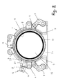
- FIG. 1 in perspective illustration a crankshaft seal flange according to the invention
- FIG. 2 the crankshaft seal flange according to the invention in a front view
- FIG. 3 in enlarged and perspective illustration, the sensor input of the crankshaft seal flange according to the invention (arrow III in FIG. 2 ).
- the seal flange serves for sealing passenger car and truck crankshafts at the front and rear.
- the seal flanges are screwed in known manner to the housings in which the crankshaft is rotatably supported.
- the seal flange has an annular support 1 which is comprised of hard plastic material.
- plastic materials for the support 1 for example, high-performance thermoplastic materials such as PPS, suitable polyamides or PPA, but also thermosetting resins are conceivable, such as phenolic resins.
- the high-performance thermoplastic materials as well as the thermosetting resins each are composites that, depending on the application, contain additives such as glass or carbon fibers, mineral fillers and the like.
- Fastening points 2 to 7 are transversely projecting away from the support 1 and each are provided with at least one through opening 8 for screws with which the seal flange is screwed onto the crankcase.
- the arrangement and configuration of the fastening points 2 to 7 depends on the configuration of the respective crankcase.
- the embodiment and arrangement of the fastening tabs 2 to 7 illustrated in FIGS. 1 and 2 is therefore not to be viewed as limiting but only represents one possible embodiment.
- the seal flange or the support 1 On its lateral face (not illustrated) facing the crankcase, the seal flange or the support 1 is provided with at least one static seal that can be embodied as a seal ring and can extend about the circumference of the support 1 .
- the static seal is fastened in a groove on the end face of the support 1 in a known way. Since such static seals on seal flanges for crankshafts are known, their configuration and arrangement is not described in detail.
- the support 1 has a through opening 22 in which a dynamic seal 11 is arranged in a known manner. It extends about the circumference of the screw opening 22 and is contacting seal-tightly the crankshaft which is extending through the support 1 .
- the dynamic seal 11 can be an elastomeric seal.
- the dynamic seal 11 is comprised of polyfluorocarbon, in particular of polytetrafluoroethylene.
- the dynamic seal 11 is comprised of friction-minimized materials so that the wear and the friction losses of the dynamic seal 11 are minimal and a long service life is ensured in this way.
- the through opening 22 has at the transition to the lateral face of the seal flange illustrated in FIGS. 1 and 2 a wall section 10 conically opening in radial outward direction and adjoined by a circumferentially extending flat annular surface 9 positioned in the lateral face. It has advantageously about most of its circumference the same radial width and is embodied to be wider in the sensor area 23 as well as in the base area 24 of the seal flange.
- the annular surface 9 as a function of the shape and/or configuration of the seal flange, can also have a different configuration.
- the illustrated and described form of the annular surface is therefore not to be understood as limiting.
- the seal flange is provided with a rotary speed and position sensor 12 (in the following referred to as sensor) which serves for motor control and interacts in a known manner with a trigger wheel that is fixedly seated on the crankshaft.
- the sensor 12 is comprised substantially of an electronic component group 13 which is integrated into the seal flange.
- the sensor 12 has a bushing part 14 that is projecting transversely away from the support 1 and into which a plug of a corresponding sensor cable can be plugged.
- This bushing part 14 is also produced when injection molding the seal flange so that it must not be mounted separately on the support 1 of the seal flange.
- the bushing part 14 has parallel extending straight wall sections 15 , 16 ( FIG. 3 ) which at their ends pass into each other by curved wall sections 17 , 18 .
- the receiving part 14 has a bottom 19 from which contacts 20 are projecting away which are conductively connected with the electronic component group 13 and which are interacting with appropriate counter contacts of the plug of the sensor cable to be plugged into the bushing part 14 .
- the sensor 12 is arranged in such a way on the annular support 1 that it is located in the area adjacent to the dynamic seal 11 . In this way, the sensor 12 can reliably interact with the trigger wheel of the crankshaft.
- the shape of the bushing part 14 depends on the installation conditions in the vehicle.
- the bushing part 14 is extending straight.
- it can also be curved across its length, have a Z-shape, or be shaped in another way, depending on the existing installation conditions in the vehicle.
- the bushing part 14 is projecting away from a base member 21 which in the illustrated embodiment has a greater cross section than the bushing part 14 .
- the base member 21 extends approximately across the entire axial width of the support 1 .
- the electronic component group 13 is located in the area of this base member 21 which is also projecting away transversely from the annular support 1 and is monolithically embodied together with it. As a result of the great cross section width of the base member 21 , the electronic component group 13 is reliably protected. Since the electronic component group 13 during injection molding is embedded in the support 1 of the seal flange, an excellent radial, tangential, and axial positioning of the component group 13 results. Since it is embedded in the material of the seal flange, it is insensitive relative to vibrations and shocks. This contributes to a high measuring precision of the sensor 12 .
- the bushing part 14 and the base member 21 can also have the same or substantially the same cross section. In such a case, the component group 13 is reliably protected also.
- the sensor 12 Since the sensor 12 must not be retrofitted as a separate component on the seal flange or its support 1 , no guides are required for the sensor which would cause interruptions in the wall section 10 and in the annular surface 9 . As a result of the closed surfaces 9 , 10 , no deposits can form in the cavities and the like, as they are found in conventional seal flanges where the sensor 12 is screwed onto the support 1 . Conversely, due to the closed surfaces 9 , 10 , it is ensured that no dirt particles can be pulled from the exterior into the interior of the seal flange.
- closed surfaces 9 , 10 are in particular advantageous when testing for seal-tightness of the seal flange by means of an overpressure bell.
- the overpressure bell With the overpressure bell, the seal-tightness of the seal flange is tested. It is attached to one end face of the seal flange in such a way that, about its circumference, it can rest seal-tightly against the annular surface 9 as well as the wall section 10 of the support 1 .
- overpressure When overpressure is now applied by means of the overpressure bell, the overpressure must be maintained for a predetermined amount of time. When this is the case, then this is an indication of the seal-tightness of the seal flange. When however the overpressure drops within the predetermined measuring time, this indicates that the seal flange has leaks.
- the seal-tightness test can be performed in a simple and reliable way.
- a pressure loss occurs within the predetermined measuring time, it can be reliably assumed that the seal flange is leaking.
- the appearance of air leaks can be very precisely measured. In this way, it is possible therefore in an advantageous way to omit oiling of the crankshaft upon installation of the seal flange, which is required in conventional seal flanges with screwed-on sensor.
- seal flange is characterized by minimal weight because the additional connecting elements required up to now for attachment of the sensor and made of metal are eliminated.
- the seal flange with sensor 12 integrated by injection molding technology can be manufactured in any suitable size. Also, positioning of the sensor 12 on the seal flange can be selected as needed so that very different seal flanges for very different motor configurations can be employed.
- the component group 13 must only be positioned within the injection molding tool at the right location. In the subsequent injection molding process, the sensor 12 is then at the right location of the seal flange.
- the sensor 12 is designed such that the sensor signal can be sent by cables to the motor control device.
- the signal transmission can however also be done wireless, for example, by radiocommunication.
Landscapes
- Engineering & Computer Science (AREA)
- General Engineering & Computer Science (AREA)
- Mechanical Engineering (AREA)
- Physics & Mathematics (AREA)
- General Physics & Mathematics (AREA)
- Chemical & Material Sciences (AREA)
- Combustion & Propulsion (AREA)
- Electromagnetism (AREA)
- Measurement Of Length, Angles, Or The Like Using Electric Or Magnetic Means (AREA)
- Transmission And Conversion Of Sensor Element Output (AREA)
Applications Claiming Priority (3)
| Application Number | Priority Date | Filing Date | Title |
|---|---|---|---|
| DE202015007951.2 | 2015-11-16 | ||
| DE202015007951U | 2015-11-16 | ||
| DE202015007951.2U DE202015007951U1 (de) | 2015-11-16 | 2015-11-16 | Kurbelwellen-Dichtflansch |
Publications (2)
| Publication Number | Publication Date |
|---|---|
| US20170138481A1 US20170138481A1 (en) | 2017-05-18 |
| US10024433B2 true US10024433B2 (en) | 2018-07-17 |
Family
ID=54867323
Family Applications (1)
| Application Number | Title | Priority Date | Filing Date |
|---|---|---|---|
| US15/351,631 Active US10024433B2 (en) | 2015-11-16 | 2016-11-15 | Crankshaft seal flange |
Country Status (4)
| Country | Link |
|---|---|
| US (1) | US10024433B2 (de) |
| EP (1) | EP3208454B1 (de) |
| CN (1) | CN106704383B (de) |
| DE (1) | DE202015007951U1 (de) |
Families Citing this family (2)
| Publication number | Priority date | Publication date | Assignee | Title |
|---|---|---|---|---|
| WO2022127974A1 (de) * | 2020-12-15 | 2022-06-23 | Schaeffler Technologies AG & Co. KG | Sensorlager mit duroplastmantel für die winkelerfassung von einer welle sowie verfahren zur fertigung des sensorlagers |
| CN115263596A (zh) * | 2022-07-25 | 2022-11-01 | 东风汽车集团股份有限公司 | 发动机 |
Citations (14)
| Publication number | Priority date | Publication date | Assignee | Title |
|---|---|---|---|---|
| US4653458A (en) * | 1984-12-20 | 1987-03-31 | Saab-Scania Aktiebolag | Arrangement for connecting a position sensing transducer to a machine |
| US5152538A (en) * | 1988-03-21 | 1992-10-06 | Chicago Rawhide Manufacturing Company, Inc. | Composite seal assembly |
| EP1063455A2 (de) | 1999-06-23 | 2000-12-27 | CR Elastomere GmbH | Dichtflansch zur Abdichtung von einem sich drehenden Maschinenteil |
| US6250637B1 (en) * | 1996-10-16 | 2001-06-26 | Sabo Industria E Comercio, Ltda. | Sealing assembly for a motor vehicle |
| US6345825B1 (en) * | 1998-08-28 | 2002-02-12 | Firma Carl Freudenberg | Sealing arrangement |
| US6533286B1 (en) * | 1996-02-15 | 2003-03-18 | Firma Carl Freudenberg | Radial shaft seal |
| US20030056609A1 (en) | 2001-08-21 | 2003-03-27 | Alexander Gorg | Mounting unit for sensor systems |
| US6561518B1 (en) * | 1999-10-25 | 2003-05-13 | Firma Carl Freudenberg | Seal arrangement with a sealing flange and a carrier flange |
| US6605938B1 (en) * | 1999-06-02 | 2003-08-12 | Koyo Seiko Co., Ltd. | Compact wheel speed detector capable of saving space and improving workability |
| US20050230920A1 (en) * | 2004-04-15 | 2005-10-20 | Federal-Mogul World Wide, Inc. | Integrated sensor-seal module for detecting angular position of a crankshaft |
| US20070104402A1 (en) | 2005-11-01 | 2007-05-10 | Jtekt Corporation | Seal device with sensor and rolling bearing device using the same |
| US7334555B2 (en) * | 2004-02-02 | 2008-02-26 | Freudenberg-Nok General Partnership | Stamped crankshaft seal retainer plate and molded encoder sensor support feature |
| US7694976B2 (en) * | 2004-06-28 | 2010-04-13 | Nok Corporation | Sealing device with sensor |
| CN203703137U (zh) | 2014-03-10 | 2014-07-09 | 董波 | 具有传感功能的总成油封 |
Family Cites Families (3)
| Publication number | Priority date | Publication date | Assignee | Title |
|---|---|---|---|---|
| NO322272B1 (no) * | 1999-03-26 | 2006-09-04 | Kongsberg Maritime As | Sensor og system for overvaking av temperatur inne i vanskelig tilgjengelige, bevegelige deler |
| DE102010028232A1 (de) * | 2010-04-27 | 2011-10-27 | Robert Bosch Gmbh | Sensorbaugruppe für ein Fahrzeug und Vorrichtung zur Erfassung von Drehbewegungen eines Radlagers |
| DE102014200273B4 (de) * | 2014-01-10 | 2018-04-19 | Ford Global Technologies, Llc | Lagerkappe |
-
2015
- 2015-11-16 DE DE202015007951.2U patent/DE202015007951U1/de not_active Expired - Lifetime
-
2016
- 2016-11-03 EP EP16002339.6A patent/EP3208454B1/de active Active
- 2016-11-15 US US15/351,631 patent/US10024433B2/en active Active
- 2016-11-16 CN CN201611034189.1A patent/CN106704383B/zh active Active
Patent Citations (14)
| Publication number | Priority date | Publication date | Assignee | Title |
|---|---|---|---|---|
| US4653458A (en) * | 1984-12-20 | 1987-03-31 | Saab-Scania Aktiebolag | Arrangement for connecting a position sensing transducer to a machine |
| US5152538A (en) * | 1988-03-21 | 1992-10-06 | Chicago Rawhide Manufacturing Company, Inc. | Composite seal assembly |
| US6533286B1 (en) * | 1996-02-15 | 2003-03-18 | Firma Carl Freudenberg | Radial shaft seal |
| US6250637B1 (en) * | 1996-10-16 | 2001-06-26 | Sabo Industria E Comercio, Ltda. | Sealing assembly for a motor vehicle |
| US6345825B1 (en) * | 1998-08-28 | 2002-02-12 | Firma Carl Freudenberg | Sealing arrangement |
| US6605938B1 (en) * | 1999-06-02 | 2003-08-12 | Koyo Seiko Co., Ltd. | Compact wheel speed detector capable of saving space and improving workability |
| EP1063455A2 (de) | 1999-06-23 | 2000-12-27 | CR Elastomere GmbH | Dichtflansch zur Abdichtung von einem sich drehenden Maschinenteil |
| US6561518B1 (en) * | 1999-10-25 | 2003-05-13 | Firma Carl Freudenberg | Seal arrangement with a sealing flange and a carrier flange |
| US20030056609A1 (en) | 2001-08-21 | 2003-03-27 | Alexander Gorg | Mounting unit for sensor systems |
| US7334555B2 (en) * | 2004-02-02 | 2008-02-26 | Freudenberg-Nok General Partnership | Stamped crankshaft seal retainer plate and molded encoder sensor support feature |
| US20050230920A1 (en) * | 2004-04-15 | 2005-10-20 | Federal-Mogul World Wide, Inc. | Integrated sensor-seal module for detecting angular position of a crankshaft |
| US7694976B2 (en) * | 2004-06-28 | 2010-04-13 | Nok Corporation | Sealing device with sensor |
| US20070104402A1 (en) | 2005-11-01 | 2007-05-10 | Jtekt Corporation | Seal device with sensor and rolling bearing device using the same |
| CN203703137U (zh) | 2014-03-10 | 2014-07-09 | 董波 | 具有传感功能的总成油封 |
Also Published As
| Publication number | Publication date |
|---|---|
| EP3208454B1 (de) | 2020-06-03 |
| EP3208454A1 (de) | 2017-08-23 |
| US20170138481A1 (en) | 2017-05-18 |
| DE202015007951U1 (de) | 2015-12-07 |
| CN106704383B (zh) | 2020-03-31 |
| CN106704383A (zh) | 2017-05-24 |
Similar Documents
| Publication | Publication Date | Title |
|---|---|---|
| US5611548A (en) | Sealing arrangement | |
| US9778146B2 (en) | Module for detecting a vibrational behavior of a mechanical component | |
| US10024433B2 (en) | Crankshaft seal flange | |
| KR102438294B1 (ko) | 인코더 및 모터 | |
| JP6035685B2 (ja) | 車輪速センサおよび車輪速センサの製造方法 | |
| US9796221B2 (en) | Module for detecting a physical value of a gaseous medium | |
| KR102094455B1 (ko) | 자동차 변속기에서 세팅 요소의 작동을 위한 유압식 작동 장치 | |
| US9801289B2 (en) | Module for a tire pressure monitoring system | |
| US10768028B2 (en) | Sensor unit for determining a rotor position of an electric motor and electric motor, preferably for a clutch actuator of a clutch actuation system of a motor vehicle | |
| US5798453A (en) | Pressure sleeve | |
| US8826753B2 (en) | Sensor apparatus with O-ring | |
| US7232129B2 (en) | Sealing apparatus with encoder | |
| US10670484B2 (en) | Pressure sensor unit including snap fit circular seal | |
| US9030191B2 (en) | Sensor subassembly for a vehicle and device for measuring rotational movements of a wheel bearing | |
| US9097285B2 (en) | Magnetic encoder type hub bearing unit | |
| US6978678B2 (en) | Pressure sensor | |
| US20080150238A1 (en) | Hermetically Sealing Device With Magnetic Encoder | |
| US20200370653A1 (en) | Seal arrangement | |
| KR101822856B1 (ko) | 실링 부재를 구비하는 차량용 액슬 어셈블리 | |
| US20220307553A1 (en) | Protective cover having sensor holder part, bearing device including the protective cover, and method of manufacturing the protective cover having the sensor holder part | |
| CA2470372A1 (en) | Measuring-point bolt | |
| US20200182726A1 (en) | Sensor element with integral supporting and sensor body | |
| US20040129768A1 (en) | Encoder-equipped seal | |
| US6366080B1 (en) | Sensor for sensing rotary movement including a stationary sensor unit and a rotatable sensor unit | |
| CN104245354A (zh) | 车轮轴承盖和车轮轴承 |
Legal Events
| Date | Code | Title | Description |
|---|---|---|---|
| AS | Assignment |
Owner name: KACO GMBH + CO. KG, GERMANY Free format text: ASSIGNMENT OF ASSIGNORS INTEREST;ASSIGNORS:LENZ, ROLAND;WERNER, ANDRE;BANTEL, JOCHEN;AND OTHERS;REEL/FRAME:041003/0426 Effective date: 20170103 |
|
| STCF | Information on status: patent grant |
Free format text: PATENTED CASE |
|
| MAFP | Maintenance fee payment |
Free format text: PAYMENT OF MAINTENANCE FEE, 4TH YEAR, LARGE ENTITY (ORIGINAL EVENT CODE: M1551); ENTITY STATUS OF PATENT OWNER: LARGE ENTITY Year of fee payment: 4 |