TWI828151B - Knee pad bracket - Google Patents
Knee pad bracket Download PDFInfo
- Publication number
- TWI828151B TWI828151B TW111118871A TW111118871A TWI828151B TW I828151 B TWI828151 B TW I828151B TW 111118871 A TW111118871 A TW 111118871A TW 111118871 A TW111118871 A TW 111118871A TW I828151 B TWI828151 B TW I828151B
- Authority
- TW
- Taiwan
- Prior art keywords
- frame
- frame body
- accommodation space
- arc portion
- vibration
- Prior art date
Links
- 210000003127 knee Anatomy 0.000 title claims abstract description 79
- 230000004308 accommodation Effects 0.000 claims description 56
- 210000000689 upper leg Anatomy 0.000 claims description 9
- 238000001514 detection method Methods 0.000 claims description 7
- 239000002184 metal Substances 0.000 claims description 5
- 229920001296 polysiloxane Polymers 0.000 claims description 5
- 229920000049 Carbon (fiber) Polymers 0.000 claims description 4
- 239000004917 carbon fiber Substances 0.000 claims description 4
- VNWKTOKETHGBQD-UHFFFAOYSA-N methane Chemical compound C VNWKTOKETHGBQD-UHFFFAOYSA-N 0.000 claims description 4
- 229920003023 plastic Polymers 0.000 claims description 4
- 230000000694 effects Effects 0.000 description 10
- 210000002414 leg Anatomy 0.000 description 9
- 244000309466 calf Species 0.000 description 7
- 238000000034 method Methods 0.000 description 7
- 230000036544 posture Effects 0.000 description 6
- 208000010040 Sprains and Strains Diseases 0.000 description 4
- 239000000463 material Substances 0.000 description 4
- 206010060820 Joint injury Diseases 0.000 description 3
- 208000016593 Knee injury Diseases 0.000 description 3
- 206010024453 Ligament sprain Diseases 0.000 description 3
- 238000010521 absorption reaction Methods 0.000 description 3
- 210000000845 cartilage Anatomy 0.000 description 3
- 210000000629 knee joint Anatomy 0.000 description 3
- 230000035939 shock Effects 0.000 description 3
- 210000004243 sweat Anatomy 0.000 description 3
- 208000006820 Arthralgia Diseases 0.000 description 2
- 238000005452 bending Methods 0.000 description 2
- 230000037237 body shape Effects 0.000 description 2
- 230000006378 damage Effects 0.000 description 2
- 238000013016 damping Methods 0.000 description 2
- 238000010586 diagram Methods 0.000 description 2
- 210000003414 extremity Anatomy 0.000 description 2
- 230000017525 heat dissipation Effects 0.000 description 2
- 208000024765 knee pain Diseases 0.000 description 2
- 230000007774 longterm Effects 0.000 description 2
- 230000035699 permeability Effects 0.000 description 2
- 210000000988 bone and bone Anatomy 0.000 description 1
- 230000005484 gravity Effects 0.000 description 1
- 238000011900 installation process Methods 0.000 description 1
- 230000009191 jumping Effects 0.000 description 1
- 230000005923 long-lasting effect Effects 0.000 description 1
- 238000012986 modification Methods 0.000 description 1
- 230000004048 modification Effects 0.000 description 1
- 230000002265 prevention Effects 0.000 description 1
- 238000004904 shortening Methods 0.000 description 1
Images


Classifications
-
- A—HUMAN NECESSITIES
- A61—MEDICAL OR VETERINARY SCIENCE; HYGIENE
- A61F—FILTERS IMPLANTABLE INTO BLOOD VESSELS; PROSTHESES; DEVICES PROVIDING PATENCY TO, OR PREVENTING COLLAPSING OF, TUBULAR STRUCTURES OF THE BODY, e.g. STENTS; ORTHOPAEDIC, NURSING OR CONTRACEPTIVE DEVICES; FOMENTATION; TREATMENT OR PROTECTION OF EYES OR EARS; BANDAGES, DRESSINGS OR ABSORBENT PADS; FIRST-AID KITS
- A61F5/00—Orthopaedic methods or devices for non-surgical treatment of bones or joints; Nursing devices; Anti-rape devices
- A61F5/01—Orthopaedic devices, e.g. splints, casts or braces
- A61F5/0102—Orthopaedic devices, e.g. splints, casts or braces specially adapted for correcting deformities of the limbs or for supporting them; Ortheses, e.g. with articulations
- A61F5/0123—Orthopaedic devices, e.g. splints, casts or braces specially adapted for correcting deformities of the limbs or for supporting them; Ortheses, e.g. with articulations for the knees
-
- A—HUMAN NECESSITIES
- A41—WEARING APPAREL
- A41D—OUTERWEAR; PROTECTIVE GARMENTS; ACCESSORIES
- A41D13/00—Professional, industrial or sporting protective garments, e.g. surgeons' gowns or garments protecting against blows or punches
- A41D13/015—Professional, industrial or sporting protective garments, e.g. surgeons' gowns or garments protecting against blows or punches with shock-absorbing means
-
- A—HUMAN NECESSITIES
- A41—WEARING APPAREL
- A41D—OUTERWEAR; PROTECTIVE GARMENTS; ACCESSORIES
- A41D13/00—Professional, industrial or sporting protective garments, e.g. surgeons' gowns or garments protecting against blows or punches
- A41D13/05—Professional, industrial or sporting protective garments, e.g. surgeons' gowns or garments protecting against blows or punches protecting only a particular body part
- A41D13/06—Knee or foot
- A41D13/065—Knee protectors
-
- A—HUMAN NECESSITIES
- A41—WEARING APPAREL
- A41D—OUTERWEAR; PROTECTIVE GARMENTS; ACCESSORIES
- A41D27/00—Details of garments or of their making
-
- A—HUMAN NECESSITIES
- A41—WEARING APPAREL
- A41D—OUTERWEAR; PROTECTIVE GARMENTS; ACCESSORIES
- A41D31/00—Materials specially adapted for outerwear
- A41D31/02—Layered materials
-
- A—HUMAN NECESSITIES
- A41—WEARING APPAREL
- A41D—OUTERWEAR; PROTECTIVE GARMENTS; ACCESSORIES
- A41D31/00—Materials specially adapted for outerwear
- A41D31/04—Materials specially adapted for outerwear characterised by special function or use
-
- A—HUMAN NECESSITIES
- A41—WEARING APPAREL
- A41D—OUTERWEAR; PROTECTIVE GARMENTS; ACCESSORIES
- A41D31/00—Materials specially adapted for outerwear
- A41D31/04—Materials specially adapted for outerwear characterised by special function or use
- A41D31/18—Elastic
-
- A—HUMAN NECESSITIES
- A61—MEDICAL OR VETERINARY SCIENCE; HYGIENE
- A61H—PHYSICAL THERAPY APPARATUS, e.g. DEVICES FOR LOCATING OR STIMULATING REFLEX POINTS IN THE BODY; ARTIFICIAL RESPIRATION; MASSAGE; BATHING DEVICES FOR SPECIAL THERAPEUTIC OR HYGIENIC PURPOSES OR SPECIFIC PARTS OF THE BODY
- A61H23/00—Percussion or vibration massage, e.g. using supersonic vibration; Suction-vibration massage; Massage with moving diaphragms
- A61H23/02—Percussion or vibration massage, e.g. using supersonic vibration; Suction-vibration massage; Massage with moving diaphragms with electric or magnetic drive
-
- A—HUMAN NECESSITIES
- A41—WEARING APPAREL
- A41D—OUTERWEAR; PROTECTIVE GARMENTS; ACCESSORIES
- A41D2400/00—Functions or special features of garments
- A41D2400/32—Therapeutic use
- A41D2400/322—Massage
-
- A—HUMAN NECESSITIES
- A41—WEARING APPAREL
- A41D—OUTERWEAR; PROTECTIVE GARMENTS; ACCESSORIES
- A41D2400/00—Functions or special features of garments
- A41D2400/80—Friction or grip reinforcement
- A41D2400/82—Friction or grip reinforcement with the body of the user
-
- A—HUMAN NECESSITIES
- A61—MEDICAL OR VETERINARY SCIENCE; HYGIENE
- A61F—FILTERS IMPLANTABLE INTO BLOOD VESSELS; PROSTHESES; DEVICES PROVIDING PATENCY TO, OR PREVENTING COLLAPSING OF, TUBULAR STRUCTURES OF THE BODY, e.g. STENTS; ORTHOPAEDIC, NURSING OR CONTRACEPTIVE DEVICES; FOMENTATION; TREATMENT OR PROTECTION OF EYES OR EARS; BANDAGES, DRESSINGS OR ABSORBENT PADS; FIRST-AID KITS
- A61F5/00—Orthopaedic methods or devices for non-surgical treatment of bones or joints; Nursing devices; Anti-rape devices
- A61F5/01—Orthopaedic devices, e.g. splints, casts or braces
- A61F2005/0197—Orthopaedic devices, e.g. splints, casts or braces with spring means
-
- A—HUMAN NECESSITIES
- A61—MEDICAL OR VETERINARY SCIENCE; HYGIENE
- A61H—PHYSICAL THERAPY APPARATUS, e.g. DEVICES FOR LOCATING OR STIMULATING REFLEX POINTS IN THE BODY; ARTIFICIAL RESPIRATION; MASSAGE; BATHING DEVICES FOR SPECIAL THERAPEUTIC OR HYGIENIC PURPOSES OR SPECIFIC PARTS OF THE BODY
- A61H2201/00—Characteristics of apparatus not provided for in the preceding codes
- A61H2201/01—Constructive details
- A61H2201/0107—Constructive details modular
-
- A—HUMAN NECESSITIES
- A61—MEDICAL OR VETERINARY SCIENCE; HYGIENE
- A61H—PHYSICAL THERAPY APPARATUS, e.g. DEVICES FOR LOCATING OR STIMULATING REFLEX POINTS IN THE BODY; ARTIFICIAL RESPIRATION; MASSAGE; BATHING DEVICES FOR SPECIAL THERAPEUTIC OR HYGIENIC PURPOSES OR SPECIFIC PARTS OF THE BODY
- A61H2201/00—Characteristics of apparatus not provided for in the preceding codes
- A61H2201/01—Constructive details
- A61H2201/0173—Means for preventing injuries
- A61H2201/0184—Means for preventing injuries by raising an alarm
-
- A—HUMAN NECESSITIES
- A61—MEDICAL OR VETERINARY SCIENCE; HYGIENE
- A61H—PHYSICAL THERAPY APPARATUS, e.g. DEVICES FOR LOCATING OR STIMULATING REFLEX POINTS IN THE BODY; ARTIFICIAL RESPIRATION; MASSAGE; BATHING DEVICES FOR SPECIAL THERAPEUTIC OR HYGIENIC PURPOSES OR SPECIFIC PARTS OF THE BODY
- A61H2201/00—Characteristics of apparatus not provided for in the preceding codes
- A61H2201/16—Physical interface with patient
- A61H2201/1602—Physical interface with patient kind of interface, e.g. head rest, knee support or lumbar support
- A61H2201/164—Feet or leg, e.g. pedal
- A61H2201/1642—Holding means therefor
-
- A—HUMAN NECESSITIES
- A61—MEDICAL OR VETERINARY SCIENCE; HYGIENE
- A61H—PHYSICAL THERAPY APPARATUS, e.g. DEVICES FOR LOCATING OR STIMULATING REFLEX POINTS IN THE BODY; ARTIFICIAL RESPIRATION; MASSAGE; BATHING DEVICES FOR SPECIAL THERAPEUTIC OR HYGIENIC PURPOSES OR SPECIFIC PARTS OF THE BODY
- A61H2201/00—Characteristics of apparatus not provided for in the preceding codes
- A61H2201/16—Physical interface with patient
- A61H2201/1602—Physical interface with patient kind of interface, e.g. head rest, knee support or lumbar support
- A61H2201/165—Wearable interfaces
- A61H2201/1652—Harness
-
- A—HUMAN NECESSITIES
- A61—MEDICAL OR VETERINARY SCIENCE; HYGIENE
- A61H—PHYSICAL THERAPY APPARATUS, e.g. DEVICES FOR LOCATING OR STIMULATING REFLEX POINTS IN THE BODY; ARTIFICIAL RESPIRATION; MASSAGE; BATHING DEVICES FOR SPECIAL THERAPEUTIC OR HYGIENIC PURPOSES OR SPECIFIC PARTS OF THE BODY
- A61H2201/00—Characteristics of apparatus not provided for in the preceding codes
- A61H2201/50—Control means thereof
- A61H2201/5058—Sensors or detectors
- A61H2201/5064—Position sensors
-
- A—HUMAN NECESSITIES
- A61—MEDICAL OR VETERINARY SCIENCE; HYGIENE
- A61H—PHYSICAL THERAPY APPARATUS, e.g. DEVICES FOR LOCATING OR STIMULATING REFLEX POINTS IN THE BODY; ARTIFICIAL RESPIRATION; MASSAGE; BATHING DEVICES FOR SPECIAL THERAPEUTIC OR HYGIENIC PURPOSES OR SPECIFIC PARTS OF THE BODY
- A61H2201/00—Characteristics of apparatus not provided for in the preceding codes
- A61H2201/50—Control means thereof
- A61H2201/5058—Sensors or detectors
- A61H2201/5069—Angle sensors
-
- A—HUMAN NECESSITIES
- A61—MEDICAL OR VETERINARY SCIENCE; HYGIENE
- A61H—PHYSICAL THERAPY APPARATUS, e.g. DEVICES FOR LOCATING OR STIMULATING REFLEX POINTS IN THE BODY; ARTIFICIAL RESPIRATION; MASSAGE; BATHING DEVICES FOR SPECIAL THERAPEUTIC OR HYGIENIC PURPOSES OR SPECIFIC PARTS OF THE BODY
- A61H2205/00—Devices for specific parts of the body
- A61H2205/10—Leg
- A61H2205/102—Knee
Abstract
Description
本發明有關一種醫療輔具,特別係指一種護膝支架。 The present invention relates to a medical assistive device, in particular to a knee brace.
護膝為常見用於保護膝蓋、或維持行走正確姿勢所使用之輔具,其中常見之護膝包含:「套筒式」,其係為一體成形之設計,可全面性地包覆人體之膝關節,然而由於其包覆面積大,長期配戴下來可能產生悶熱之感受;「纏繞式」,其係可依據不同使用者之體型大小來調整護膝之鬆緊,一般而言,其調整鬆緊之方式係使用魔鬼氈,由於魔鬼氈之彈性不佳,因此無法達成良好之減振效果;以及「機械骨式」,其係為強力,對抗式固定,由於其使用之方式與安裝流程煩瑣麻煩、容易滑落、且價格偏高,因此一般人難以負擔。此外,於習知所見之護膝產品中,一般僅能達成「固定」之用途,若於膝蓋痠痛時,無有效之方法來緩解膝蓋之痠痛感。綜上所述,提供一種穿戴舒適、能將人體腿部所受各方向之作用力進行抵消,以舒緩膝蓋所受之壓力、固定性持久、或可按摩膝蓋之護膝實為時勢所需。 Knee pads are commonly used assistive devices to protect the knees or maintain correct walking posture. Common knee pads include: "sleeve type", which are one-piece designs that can comprehensively cover the human knee joint. However, due to its large covering area, wearing it for a long time may cause a stuffy feeling. "Wrap type" can adjust the tightness of the knee pads according to the body size of different users. Generally speaking, the way to adjust the tightness is to use Devil felt, because the elasticity of devil felt is poor, it cannot achieve good vibration damping effect; and "mechanical bone type", which is a strong, confrontational fixation, due to its use method and installation process is cumbersome, easy to slip, And the price is on the high side, making it unaffordable for the average person. In addition, the commonly seen knee brace products can generally only achieve the purpose of "fixing". If the knee is sore, there is no effective way to relieve the soreness of the knee. In summary, it is necessary to provide a knee pad that is comfortable to wear, can offset the forces in all directions on the human leg, relieve the pressure on the knee, has long-lasting fixation, or can massage the knee.
本發明所欲解決之問題在於:提供一種具有減震、和按摩功能之護膝支架,以保護穿戴者之膝部。 The problem to be solved by the present invention is to provide a knee support bracket with shock absorption and massage functions to protect the wearer's knees.
為解決上述之問題,本發明提供一種護膝支架,包含:一第一架體,包含:一第一弧部、以及二第一支撐桿,其中該等第一支撐桿係分別設置於 該第一弧部相對應之兩端;一第二架體,包含:一第二弧部、以及二第二支撐桿,其中該等第二支撐桿係分別設置於該第二弧部相對應之兩端,其中該第一弧部與該第二弧部相對應地設置,以界定一第一容置空間,其中該第一容置空間可供一人體之大腿容置;一第三架體,係與該第一架體相對應地設置,包含:一第三弧部、以及二第三支撐桿,其中該等第三支撐桿係分別設置於該第三弧部相對應之兩端;一第四架體,係與該第二架體相對應地設置,包含:一第四弧部、以及二第四支撐桿,其中該等第四支撐桿係分別設置於該第四弧部相對應之兩端,其中該第四弧部與該第三弧部相對應地設置,以界定一第二容置空間,其中該第一容置空間與該第二容置空間相連通、以及該第二容置空間可供一人體之小腿容置;一樞轉軸,係可分離地樞設於該第一架體、該第二架體、該第三架體、與該第四架體相對應之兩側,並可樞合該第一支撐桿、該第二支撐桿、該第三支撐桿、以及該第四支撐桿;一第一彈力元件,其兩端分別設置於該第一架體、以及該第二架體相對於該第一容置空間之同一側;以及一第二彈力元件,其兩端分別設置於該第三架體、以及該第四架體相對於該第二容置空間之同一側。 In order to solve the above problems, the present invention provides a knee brace bracket, which includes: a first frame body, including: a first arc portion, and two first support rods, wherein the first support rods are respectively arranged on Two corresponding ends of the first arc portion; a second frame body including: a second arc portion and two second support rods, wherein the second support rods are respectively provided at corresponding ends of the second arc portion. At both ends, the first arc portion and the second arc portion are arranged correspondingly to define a first accommodation space, wherein the first accommodation space can accommodate the thigh of a human body; a third frame The body is arranged corresponding to the first frame body and includes: a third arc portion and two third support rods, wherein the third support rods are respectively arranged at two corresponding ends of the third arc portion. ; A fourth frame body is provided correspondingly to the second frame body, including: a fourth arc portion and two fourth support rods, wherein the fourth support rods are respectively disposed on the fourth arc portion Corresponding two ends, wherein the fourth arc portion and the third arc portion are provided correspondingly to define a second accommodation space, wherein the first accommodation space is connected with the second accommodation space, and The second accommodation space can accommodate the calf of a human body; a pivot axis is detachably pivoted on the first frame body, the second frame body, the third frame body, and the fourth frame body. Corresponding two sides, and can pivot the first support rod, the second support rod, the third support rod, and the fourth support rod; a first elastic element, its two ends are respectively arranged on the first The frame body and the second frame body are on the same side relative to the first accommodation space; and a second elastic element has its two ends respectively disposed on the third frame body and the fourth frame body relative to the third frame body. The same side of the two accommodation spaces.
更佳者,其中:該第一架體係由複數第一子架體相互堆疊所形成,並且兩兩該第一子架體間可相對地移動;該第二架體係由複數第二子架體相互堆疊所形成,並且兩兩該第二子架體間可相對地移動;該第三架體係由複數第三子架體相互堆疊所形成,並且兩兩該第三子架體間可相對地移動;以及該第四架體係由複數第四子架體相互堆疊所形成,並且兩兩該第四子架體間可相對地移動。 Even better, wherein: the first frame system is formed by stacking a plurality of first subframe bodies, and each pair of the first subframe bodies can move relatively; the second frame system is formed by a plurality of second subframe bodies. The third subrack system is formed by stacking a plurality of third subrack bodies on top of each other, and the second subrack bodies in pairs can move relatively. Movement; and the fourth rack system is formed by stacking a plurality of fourth subrack bodies on top of each other, and two fourth subrack bodies can move relative to each other.
更佳者,其中更包含一緩衝墊,係設置於該第一架體與該第一容置空間接觸之一側;該第二架體與該第一容置空間接觸之一側;該第三架體與該第二容置空間接觸之一側;或該第四架體與該第二容置空間接觸之一側。 Better yet, it further includes a buffer pad, which is provided on the side of the first frame that contacts the first accommodation space; the side of the second frame that contacts the first accommodation space; The side of the three frame body in contact with the second accommodation space; or the side of the fourth frame body in contact with the second accommodation space.
更佳者,其中該第一架體、該第二架體、該第三架體、以及該第四架體之材質包含:塑膠、矽膠、碳纖維、或超薄韌性金屬片。 Even better, the materials of the first frame, the second frame, the third frame, and the fourth frame include: plastic, silicone, carbon fiber, or ultra-thin tough metal sheets.
更佳者,其中:該第一弧部之中心軸、與該第一支撐桿之中心軸形成一夾角θ1,其中θ1面向該第三架體,且135°


更佳者,其中:θ1=θ2=θ3=θ4。 Better yet, where: θ 1=θ2=θ3=θ4.
更佳者,其中更包含:一震動模組,係設置於該第一架體相對於該第一容置空間之一側;該第二架體相對於該第一容置空間之一側;該第三架體相對於該第二容置空間之一側;或該第四架體相對於該第二容置空間之一側。 Better yet, it further includes: a vibration module, which is disposed on one side of the first frame relative to the first accommodation space; and on one side of the second frame relative to the first accommodation space; One side of the third frame body is relative to the second accommodation space; or one side of the fourth frame body is relative to the second accommodation space.
更佳者,其中更包含:一控制模組,其係與該震動模組電連接、以及與一觸控裝置訊號連接,其中:該控制模組包含:一資料輸出單元,其中:該資料輸出單元可將該震動模組之震動頻率、震動速度、與震動方向轉換為一震動資訊,並將該震動資訊傳送至該觸控裝置上;以及一資料輸入單元,其中:該觸控裝置可將該震動資訊進行調整,並將調整完畢之震動資訊傳送至該資料輸入單元,以使該控制模組調控該震動模組之震動速率、震動頻率、以及震動方向。 Better yet, it further includes: a control module electrically connected to the vibration module and signal connected to a touch device, wherein: the control module includes: a data output unit, wherein: the data output The unit can convert the vibration frequency, vibration speed, and vibration direction of the vibration module into vibration information, and transmit the vibration information to the touch device; and a data input unit, wherein: the touch device can The vibration information is adjusted, and the adjusted vibration information is transmitted to the data input unit, so that the control module controls the vibration rate, vibration frequency, and vibration direction of the vibration module.
更佳者,其中更包含:一傾倒感測模組,係與該控制模組電連接,其中該傾倒感測模組可偵測該護膝支架之傾斜角度,將其儲存成一傾斜資訊,並將該傾斜資訊傳送至該資料輸入單元;以及一警示模組,係與該控制模組電連接,其中:當該傾斜資訊急遽變化時,該控制模組會連通該警示模組,以使該警示模組產生一警示訊號,並經由該資料輸出單元將該警示訊號傳送至該觸控裝置。 Better yet, it further includes: a tilt sensing module electrically connected to the control module, wherein the tilt sensing module can detect the tilt angle of the knee brace bracket, store it as tilt information, and store it as tilt information. The tilt information is transmitted to the data input unit; and a warning module is electrically connected to the control module, wherein: when the tilt information changes suddenly, the control module will connect to the warning module so that the warning module The module generates a warning signal and transmits the warning signal to the touch device through the data output unit.
更佳者,其中更包含:一距離偵測模組,係與該控制模組電連接,其中:該距離偵測模組可偵測該護膝支架與周遭環境之距離,以儲存成一距離資訊,並將該距離資訊送至該資料輸入單元;以及一警示模組,係與該控制模組電連接,其中當該距離資訊小於30cm時,該控制模組會連通該警示模組,以使該警示模組產生一警示訊號,並經由該資料輸出單元將該警示訊號傳送至該觸控裝置。 Better yet, it further includes: a distance detection module electrically connected to the control module, wherein: the distance detection module can detect the distance between the knee brace bracket and the surrounding environment to store distance information, and sends the distance information to the data input unit; and a warning module is electrically connected to the control module, wherein when the distance information is less than 30cm, the control module will connect to the warning module so that the The warning module generates a warning signal and transmits the warning signal to the touch device through the data output unit.
更佳者,其中更包含:一定位模組,係與該控制模組電連接,其中該定位模組可根據該護膝支架之地理位置儲存一位置資訊,並利用該資料輸出單元將該位置資訊傳送至該觸控裝置。 Better still, it further includes: a positioning module electrically connected to the control module, wherein the positioning module can store a position information according to the geographical location of the knee brace bracket, and use the data output unit to transmit the position information sent to the touch device.
本發明相對於先前技術之功效在於:本發明之護膝支架可將人體腿部所受各方向之作用力進行抵消,以舒緩膝蓋所受之壓力、以及避免運動幅度過大、或動作不正確而產生扭傷、或過度磨損膝關節軟骨;本發明之震動模組可按摩膝蓋,並且可透過穿戴裝置、手機、或平板來控制震動之速率、頻率、與方向,以有效舒緩穿戴者膝蓋之痠痛感;本發明兼具套筒式護膝、以及纏繞式護膝之優點,其結構之穩定性高,並且可依據不同之使用者之體型來調整第一彈性元件、以及第二彈性元件之鬆緊度,此外,本發明之護膝支架透氣性、與散熱性佳, 穿戴舒適、適合長期配戴;以及本發明之護膝支架係由多層結構所組成,因此具有更高之結構強度、與耐彎折之性能,擁有更長之使用壽命。 Compared with the prior art, the effect of the present invention is that the knee support bracket of the present invention can offset the forces in all directions on the human legs, so as to relieve the pressure on the knees and avoid excessive movement or incorrect movements. Sprain or excessive wear of knee joint cartilage; the vibration module of the present invention can massage the knee, and the speed, frequency, and direction of vibration can be controlled through a wearable device, mobile phone, or tablet to effectively relieve the soreness of the wearer's knee; The present invention combines the advantages of sleeve-type knee pads and wrap-type knee pads. Its structure has high stability, and the tightness of the first elastic element and the second elastic element can be adjusted according to the body shape of different users. In addition, The knee brace brace of the present invention has good air permeability and heat dissipation properties. It is comfortable to wear and suitable for long-term wear; and the knee brace bracket of the present invention is composed of a multi-layer structure, so it has higher structural strength, resistance to bending, and longer service life.
1:第一架體 1: The first frame
2:第一弧部 2:The first arc
3:第一支撐桿 3: First support rod
4:第二架體 4:Second frame
5:第二弧部 5:Second Arc
6:第二支撐桿 6:Second support rod
7:第一容置空間 7: First accommodation space
8:第三架體 8:Third frame
9:第三弧部 9:The third arc
10:第三支撐桿 10:Third support rod
11:第四架體 11:The fourth frame
12:第四弧部 12:The fourth arc
13:第四支撐桿 13:Fourth support rod
14:第二容置空間 14:Second accommodation space
15:樞轉軸 15: Pivot axis
16:震動模組 16:Vibration module
17:第一彈力元件 17: First elastic element
18:第二彈力元件 18: Second elastic element
19:控制模組 19:Control module
20:觸控裝置 20:Touch device
21:資料輸出單元 21: Data output unit
22:資料輸入單元 22: Data input unit
23:定位模組 23: Positioning module
24:傾倒感測模組 24: Tipping sensing module
25:警示模組 25:Alert module
26:距離偵測模組 26: Distance detection module
27:第一子架體 27:First subframe
28:第二子架體 28:Second subframe
29:第三子架體 29:Third subframe
30:第四子架體 30: The fourth subframe
31:緩衝墊 31: Cushion pad
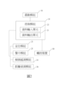
圖1A至1C為一系列之結構圖,用以說明本發明之結構特徵;圖2為一方塊圖,用以說明本發明各模組間之連結關係。 1A to 1C are a series of structural diagrams to illustrate the structural features of the present invention; FIG. 2 is a block diagram to illustrate the connection relationship between the various modules of the present invention.
為讓本發明上述及/或其他目的、功效、特徵更明顯易懂,下文特舉較佳實施方式,作詳細說明於下:本發明提供一種護膝支架,如圖1A所示,包含:一第一架體(1),包含:一第一弧部(2)、以及二第一支撐桿(3),其中該等第一支撐桿(3)係分別設置於該第一弧部(2)相對應之兩端;一第二架體(4),包含:一第二弧部(5)、以及二第二支撐桿(6),其中該等第二支撐桿(6)係分別設置於該第二弧部(5)相對應之兩端,其中該第一弧部(2)與該第二弧部(5)相對應地設置,以界定一第一容置空間(7),其中該第一容置空間(7)可供一人體之大腿容置;一第三架體(8),係與該第一架體(1)相對應地設置,包含:一第三弧部(9)、以及二第三支撐桿(10),其中該等第三支撐桿(10)係分別設置於該第三弧部(9)相對應之兩端;一第四架體(11),係與該第二架體(4)相對應地設置,包含:一第四弧部(12)、以及二第四支撐桿(13),其中該等第四支撐桿(13)係分別設置於該第四弧部(12)相對應之兩端,其中該第四弧部(12)與該第三弧部(9)相對應地設置,以界定一第二容置空間(14),其中該第一容置空間(7)與該第二容置空間(14)相連通、以及該第二容置空間(14)可供一人體之小腿容置;以及一樞轉軸(15),係可分離地樞設於該第一架體(1)、該第二 架體(4)、該第三架體(8)、與該第四架體(11)相對應之兩側,並可樞合該第一支撐桿(3)、該第二支撐桿(6)、該第三支撐桿(10)、以及該第四支撐桿(13)。其中可以理解地,該第一弧部(2)、以及該第二弧部(5)與該第一容置空間(7)接觸之一側,係相互間隔地與大腿之外緣接觸,以完成第一架體(1)、與第二架體(4)之定位;以及該第三弧部(9)、以及該第四弧部(12)與該第二容置空間(14)接觸之一側,係相互間隔地與小腿之外緣接觸,以完成第三架體(8)、與第四架體(11)之定位。於一較佳實施例中,其中該第一架體(1)、該第二架體(4)、該第三架體(8)、以及該第四架體(11)之材質包含:塑膠、矽膠、碳纖維、或超薄韌性金屬片,但不以此為限。 In order to make the above and/or other objects, effects, and features of the present invention more obvious and easy to understand, preferred embodiments are listed below and described in detail below: The present invention provides a knee brace bracket, as shown in Figure 1A, including: a first A body (1) includes: a first arc portion (2) and two first support rods (3), wherein the first support rods (3) are respectively arranged on the first arc portion (2) Corresponding two ends; a second frame body (4), including: a second arc portion (5), and two second support rods (6), wherein the second support rods (6) are respectively arranged on Two corresponding ends of the second arc portion (5), wherein the first arc portion (2) and the second arc portion (5) are arranged correspondingly to define a first accommodation space (7), wherein The first accommodation space (7) can accommodate the thigh of a human body; a third frame body (8) is provided corresponding to the first frame body (1) and includes: a third arc portion ( 9), and two third support rods (10), wherein the third support rods (10) are respectively provided at the corresponding two ends of the third arc portion (9); a fourth frame body (11), It is arranged corresponding to the second frame body (4) and includes: a fourth arc portion (12) and two fourth support rods (13), wherein the fourth support rods (13) are respectively arranged on Two corresponding ends of the fourth arc portion (12), wherein the fourth arc portion (12) and the third arc portion (9) are provided correspondingly to define a second accommodation space (14), wherein The first accommodation space (7) is connected with the second accommodation space (14), and the second accommodation space (14) can accommodate a human body's lower leg; and a pivot axis (15) is Detachably pivoted on the first frame (1), the second The frame body (4), the third frame body (8), and the two sides corresponding to the fourth frame body (11) can pivot the first support rod (3) and the second support rod (6). ), the third support rod (10), and the fourth support rod (13). It can be understood that the first arc portion (2) and the side of the second arc portion (5) in contact with the first accommodation space (7) are in contact with the outer edge of the thigh at a distance from each other, so as to Complete the positioning of the first frame body (1) and the second frame body (4); and the third arc portion (9) and the fourth arc portion (12) are in contact with the second accommodation space (14) One side is in contact with the outer edge of the calf at intervals to complete the positioning of the third frame body (8) and the fourth frame body (11). In a preferred embodiment, the materials of the first frame (1), the second frame (4), the third frame (8), and the fourth frame (11) include: plastic. , silicone, carbon fiber, or ultra-thin tough metal sheet, but not limited to this.
更佳者,為了增加各架體與樞轉軸(15)間之結合強度,以避免各架體相對於樞轉軸(15)樞轉時,該樞轉軸(15)產生損壞、或斷裂,其中:該樞轉軸(15)之材質為金屬,但不以此為限。於一較佳實施例中,該樞轉軸(15)包含一旋轉軸心,其中該旋轉軸心係以螺絲進行安裝,但不以此為限。於另一較佳實施例中,設置該樞轉軸(15)之目的在於:使各架體可相對於該樞轉軸(15)樞轉,因此,當人體腿部於運動過程中、或彎曲時,各架體可根據腿部之運動動作相對應地調整位置,以使人體腿部於各種姿勢、或動作下皆能達成減震、調整姿勢、與預防扭傷之功效。於又一較佳實施例中,本發明之護膝支架可穩定人體四肢關節之部分,以削減四肢關節周圍之劇烈震動、與扭動,並提升人體於運動過程中之穩定性與安全性;以及各架體之結構具有一定之彈性,因此當人體膝蓋受上下(垂直)、或左右(平行)之力作用時,各架體可分擔人體膝蓋所受之力,並產生一定之形變,並於各架體無受外力作用時,各架體可依其本身之彈性恢復原狀。 Even better, in order to increase the bonding strength between each frame body and the pivot shaft (15) to avoid damage or breakage of the pivot shaft (15) when each frame body pivots relative to the pivot shaft (15), where: The pivot shaft (15) is made of metal, but is not limited thereto. In a preferred embodiment, the pivot axis (15) includes a rotation axis, wherein the rotation axis is installed with screws, but is not limited to this. In another preferred embodiment, the purpose of providing the pivot axis (15) is to enable each frame to pivot relative to the pivot axis (15). Therefore, when the human leg is in motion or bent, , each frame can adjust its position accordingly according to the movements of the legs, so that the human legs can achieve the effects of shock absorption, posture adjustment, and sprain prevention in various postures or movements. In another preferred embodiment, the knee brace brace of the present invention can stabilize parts of the human body's limb joints to reduce severe vibrations and twists around the limb joints, and improve the stability and safety of the human body during exercise; and The structure of each frame has a certain degree of elasticity. Therefore, when the human knee is subjected to up and down (vertical) or left and right (parallel) forces, each frame can share the force on the human knee and produce a certain deformation. When each frame body is not acted upon by external force, each frame body can return to its original shape according to its own elasticity.
更佳者,為了對人體膝蓋進行按摩,以舒緩膝蓋之疼痛、或緩解膝蓋之壓力,如圖1A所示,其中更包含:一震動模組(16),係設置於該第一架體(1)相對於該第一容置空間(7)之一側;該第二架體(4)相對於該第一容置空間(7)之一側;該第三架體(8)相對於該第二容置空間(14)之一側;或該第四架體(11)相對於該第二容置空間(14)之一側。其中可以理解地,該震動模組(16)不與該第一容置空間(7)、或該第二容置空間(14)接觸之目的係在於:避免人體腿部直接與該震動模組(16)接觸,而導致膝蓋震動過於激烈而對其舒緩造成反效果;或避免汗水與該震動模組(16)接觸,具體而言,若人體出汗時,該震動模組(16)直接與人體接觸,則可能導致汗水滲入震動模組(16)中,而造成震動模組(16)損壞,使護膝支架之使用壽命大大縮減。於一較佳實施例中,為了對膝蓋周圍均勻地按摩、或增加按摩力道,其中可於該第一架體(1)、第二架體(4)、第三架體(8)、或第四架體(11)上增設更多之震動模組(16),其中可以理解地,各支架上所設置之震動模組(16)之數量可為相同、或不同,較佳地,當各支架上設置之震動模組(16)數量一致時,該護膝支架可均勻地對人體膝蓋進行按摩。於一較佳實施例中,該震動模組(16)為一馬達,但不以此為限。 Better still, in order to massage human knees to relieve knee pain or relieve knee pressure, as shown in Figure 1A, it further includes: a vibration module (16), which is installed on the first frame ( 1) One side relative to the first accommodation space (7); the second frame body (4) relative to one side of the first accommodation space (7); the third frame body (8) relative to One side of the second accommodation space (14); or one side of the fourth frame body (11) relative to the second accommodation space (14). It can be understood that the purpose of the vibration module (16) not contacting the first accommodation space (7) or the second accommodation space (14) is to avoid human legs from directly contacting the vibration module. (16) contact, which will cause the knee to vibrate too intensely and have the opposite effect on its relief; or avoid contact between sweat and the vibration module (16). Specifically, if the human body sweats, the vibration module (16) will directly Contact with the human body may cause sweat to penetrate into the vibration module (16), causing damage to the vibration module (16) and greatly shortening the service life of the knee brace bracket. In a preferred embodiment, in order to massage evenly around the knees or increase the massage force, the first frame (1), the second frame (4), the third frame (8), or More vibration modules (16) are added to the fourth frame (11). It can be understood that the number of vibration modules (16) provided on each bracket can be the same or different. Preferably, when When the number of vibration modules (16) provided on each bracket is the same, the knee brace bracket can massage the human knee evenly. In a preferred embodiment, the vibration module (16) is a motor, but it is not limited to this.
更佳者,為了抵消人體膝蓋對護膝支架所施予之壓力,使膝蓋作動時能達成減振之效果、並減輕膝蓋之負擔,如圖1A所示,其中更包含:一第一彈力元件(17),其兩端分別設置於該第一架體(1)、以及該第二架體(4)相對於該第一容置空間(7)之同一側;以及一第二彈力元件(18),其兩端分別設置於該第三架體(8)、以及該第四架體(11)相對於該第二容置空間(14)之同一側。於一較佳實施例中,該第一彈力元件(17)之一端係固設於該第一架體(1)、以及另一端係可移動地設置於該第二架體(4),其中:該第一彈力元件(17)可相對於該第二架體(4)移 動,使該第一架體(1)相對於該樞轉軸(15)樞轉,以接近、或遠離該第二架體(4);或該第一彈力元件(17)之一端係固設於該第二架體(4)、以及另一端係可移動地設置於該第一架體(1),其中:該第一彈力元件(17)可相對於該第一架體(1)移動,使該第二架體(4)相對於該樞轉軸(15)樞轉,以接近、或遠離該第一架體(1)。於另一較佳實施例中,該第一彈力元件(17)之一端係可移動地設置於該第一架體(1)、以及另一端係可移動地設置於該第二架體(4),其中:該第一彈力元件(17)可相對於該第二架體(4)移動,使該第一架體(1)相對於該樞轉軸(15)樞轉,以接近、或遠離該第二架體(4);以及該第一彈力元件(17)可相對於該第一架體(1)移動,使該第二架體(4)相對於該樞轉軸(15)樞轉,以接近、或遠離該第一架體(1)。於又一較佳實施例中,為了增加該第一架體(1)與該第二架體(4)間之固定性,其中更包含:一第三彈力元件,其兩端分別設置於該第一架體(1)、與該第二架體(4)相對於該第一彈力元件(17)之同一側。具體而言,該第三彈力元件與該第一架體(1)、以及第二架體(4)之連接方式;與該第一彈力元件(17)與該第一架體(1)、以及第二架體(4)之連接方式相同,因此在此不多做贅述。 Even better, in order to offset the pressure exerted by the human knee on the knee support bracket, so as to achieve a vibration-absorbing effect when the knee moves and reduce the burden on the knee, as shown in Figure 1A, it further includes: a first elastic element ( 17), its two ends are respectively arranged on the same side of the first frame body (1) and the second frame body (4) relative to the first accommodation space (7); and a second elastic element (18) ), its two ends are respectively arranged on the same side of the third frame body (8) and the fourth frame body (11) relative to the second accommodation space (14). In a preferred embodiment, one end of the first elastic element (17) is fixedly mounted on the first frame (1), and the other end is movably mounted on the second frame (4), wherein : The first elastic element (17) can move relative to the second frame (4) move to make the first frame (1) pivot relative to the pivot axis (15) to approach or move away from the second frame (4); or one end of the first elastic element (17) is fixed The second frame body (4) and the other end are movably arranged on the first frame body (1), wherein: the first elastic element (17) can move relative to the first frame body (1) , the second frame body (4) is pivoted relative to the pivot axis (15) to approach or move away from the first frame body (1). In another preferred embodiment, one end of the first elastic element (17) is movably disposed on the first frame (1), and the other end is movably disposed on the second frame (4). ), wherein: the first elastic element (17) can move relative to the second frame body (4), so that the first frame body (1) pivots relative to the pivot axis (15) to approach or move away from The second frame (4); and the first elastic element (17) can move relative to the first frame (1), so that the second frame (4) pivots relative to the pivot axis (15) , to approach or stay away from the first frame (1). In another preferred embodiment, in order to increase the fixation between the first frame body (1) and the second frame body (4), it further includes: a third elastic element, the two ends of which are respectively arranged on the The first frame body (1) and the second frame body (4) are on the same side relative to the first elastic element (17). Specifically, the connection method between the third elastic element and the first frame body (1) and the second frame body (4); and the connection method between the first elastic element (17) and the first frame body (1), The connection method of the second frame body (4) is the same, so no further details will be given here.
更佳者,該第二彈力元件(18)之一端係固設於該第三架體(8)、以及另一端係可移動地設置於該第四架體(11),如圖1A所示,其中:該第二彈力元件(18)可相對於該第四架體(11)移動,使該第三架體(8)相對於該樞轉軸(15)樞轉,以接近、或遠離該第四架體(11);或該第二彈力元件(18)之一端係固設於該第四架體(11)、以及另一端係可移動地設置於該第三架體(8),其中:該第二彈力元件(18)可相對於該第三架體(8)移動,使該第四架體(11)相對於該樞轉軸(15)樞轉,以接近、或遠離該第三架體(8)。於一較佳實施例中,該第二彈力元件(18)之一端係可移動地設置於該第三架體(8)、以及另一端係可移動地設置於該第四架體(11),其 中:該第二彈力元件(18)可相對於該第四架體(11)移動,使該第三架體(8)相對於該樞轉軸(15)樞轉,以接近、或遠離該第四架體(11);以及該第二彈力元件(18)可相對於該第三架體(8)移動,使該第四架體(11)相對於該樞轉軸(15)樞轉,以接近、或遠離該第三架體(8)。於另一較佳實施例中,為了增加該第三架體(8)與該第四架體(11)間之固定性,其中更包含:一第四彈力元件,其兩端分別設置於該第三架體(8)、與該第四架體(11)相對於該第二彈力元件(18)之同一側。具體而言,該第四彈力元件與該第三架體(8)、以及第四架體(11)之連接方式;與該第二彈力元件(18)與該第三架體(8)、以及第四架體(11)之連接方式相同,因此在此不多做贅述。 Better yet, one end of the second elastic element (18) is fixedly mounted on the third frame (8), and the other end is movably mounted on the fourth frame (11), as shown in Figure 1A , wherein: the second elastic element (18) can move relative to the fourth frame (11), allowing the third frame (8) to pivot relative to the pivot axis (15) to approach or move away from the The fourth frame body (11); or one end of the second elastic element (18) is fixedly mounted on the fourth frame body (11), and the other end is movably mounted on the third frame body (8), Wherein: the second elastic element (18) can move relative to the third frame body (8), so that the fourth frame body (11) pivots relative to the pivot axis (15) to approach or move away from the third frame body (8). Tripod (8). In a preferred embodiment, one end of the second elastic element (18) is movably disposed on the third frame body (8), and the other end is movably disposed on the fourth frame body (11). ,That Middle: The second elastic element (18) can move relative to the fourth frame body (11), so that the third frame body (8) pivots relative to the pivot axis (15) to approach or move away from the third frame body (11). Four frames (11); and the second elastic element (18) can move relative to the third frame (8), so that the fourth frame (11) pivots relative to the pivot axis (15), so as to Approach or stay away from the third frame body (8). In another preferred embodiment, in order to increase the fixation between the third frame body (8) and the fourth frame body (11), it further includes: a fourth elastic element with both ends respectively provided on the The third frame body (8) is on the same side as the fourth frame body (11) relative to the second elastic element (18). Specifically, the connection method between the fourth elastic element and the third frame body (8) and the fourth frame body (11); and the connection method between the second elastic element (18) and the third frame body (8), The connection method of the fourth frame body (11) is the same, so no further details will be given here.
更佳者,該第一彈力元件(17)、該第二彈力元件(18)、該第三彈力元件、或該第四彈力元件係為一運動繃帶,但不以此為限。於一較佳實施例中,設置該第一彈力元件(17)、或該第三彈力元件之目的係為了使第一架體(1)、與第二架體(4)緊密貼合人體大腿,並對大腿施加一定之壓力,使人體行走時能穩定姿勢、以及減少震動;以及設置該第二彈力元件(18)、或該第四彈力元件之目的係為了使第三架體(8)、與第四架體(11)緊密貼合人體小腿,並對小腿施加一定之壓力,使人體行走時能穩定姿勢、以及減少震動。 More preferably, the first elastic element (17), the second elastic element (18), the third elastic element, or the fourth elastic element is a sports bandage, but is not limited to this. In a preferred embodiment, the purpose of providing the first elastic element (17) or the third elastic element is to make the first frame (1) and the second frame (4) closely fit the human thigh. , and exerts a certain amount of pressure on the thighs, so that the human body can stabilize its posture and reduce vibrations when walking; and the purpose of arranging the second elastic element (18) or the fourth elastic element is to make the third frame body (8) , and the fourth frame body (11) closely fits the human body's calf, and exerts a certain amount of pressure on the calf, so that the human body can stabilize its posture and reduce vibration when walking.
更佳者,為了便於各架體間之樞轉,使大腿、與小腿可緊密地與各架體貼合,如圖1B所示,其中:該第一弧部(2)之中心軸、與該第一支撐桿(3)之中心軸形成一夾角θ1,其中θ1面向該第三架體(8),且135°


更佳者,如圖1C所示,其中:該第一架體(1)係由複數第一子架體(27)相互堆疊所形成,並且兩兩該第一子架體(27)間可相對地移動;該第二架體(4)係由複數第二子架體(28)相互堆疊所形成,並且兩兩該第二子架體(28)間可相對地移動;該第三架體(8)係由複數第三子架體(29)相互堆疊所形成,並且兩兩該第三子架體(29)間可相對地移動;以及該第四架體(11)係由複數第四子架體(30)相互堆疊所形成,並且兩兩該第四子架體(30)間可相對地移動。具體而言,兩兩第一子架體(27)、兩兩第二子架體(28)、兩兩第三子架體(29)、以及兩兩第四子架體(30)間不互相黏合,因此當人體膝蓋產生彎曲、或震動時,兩兩第一子架體(27)、兩兩第二子架體(28)、兩兩第三子架體(29)、以及兩兩第四子架體(30)間會相對地移動,以產生一摩擦力,其中:該摩擦力可抵消人體膝蓋對各架體所施予之力量,因此可減少膝蓋所受之作用力,以減輕膝蓋之負荷。舉例來說,當人體進行跑步、跳躍、深蹲、擺動、或甩動時,本發明之護膝支架可將人體腿部所受各方向之作用力進行抵消,以舒緩膝蓋所受之壓力、以及避免運動幅度過大、或動作不正確而產生扭傷、或過度磨損膝關節軟骨。於一較佳實施例中,當第一子架體(27)、第二子架體(28)、第三子架體(29)、或第四子架體(30)之數量越多時,所產生之摩擦力越大,因此能產生越好之減振效果,但是,為了避免摩擦力過大、而使人體腿部難以舒展,較佳地,第一子架體(27)之數量為A,且7>A>1;第二子架體(28)之數量為B,且7>B>1;第三子架體(29)之數量為C,且7>C>1;以及第四子架體(30)之數量為D,且7>D>1。於另一較佳實施例中,當啟動該震動模組(16)時,除了可 對膝蓋進行按摩外,更可提升該護膝支架之減震效果。於又一較佳實施例中,該震動模組(16)為一馬達,但不以此為限。於又一較佳實施例中,其中該第一子架體(27)、該第二子架體(28)、該第三子架體(29)、以及該第四子架體(30)之材質包含:塑膠、矽膠、碳纖維、或超薄韌性金屬片,但不以此為限。具體而言,當各架體於承受負載衝擊時,會形成一種伸展運動,使子架體、與子架體之間產生強烈摩擦(擠壓拉伸現象),同時兩個摩擦表面就會產生兩個不同方向的運動摩擦力,以達成減震之目的。於又一較佳實施例中,為了增加大腿、或小腿配戴該護膝支架之舒適性,以減小該護膝支架對人體大腿、或小腿之壓迫感,其中更包含:一緩衝墊(31),係設置於該第一架體(1)與該第一容置空間(7)接觸之一側;該第二架體(4)與該第一容置空間(7)接觸之一側;該第三架體(8)與該第二容置空間(14)接觸之一側;或該第四架體(11)與該第二容置空間(14)接觸之一側。於又一較佳實施例中,該緩衝墊(31)之材質係包含凝膠、矽膠、或橡膠,但不以此為限。 Even better, as shown in Figure 1C, the first frame body (1) is formed by stacking a plurality of first sub-frame bodies (27), and two first sub-frame bodies (27) can be spaced apart. Move relatively; the second frame (4) is formed by stacking a plurality of second subframes (28), and two second subframes (28) can move relatively; the third frame The body (8) is formed by stacking a plurality of third sub-frame bodies (29) on each other, and the third sub-frame bodies (29) in pairs can move relatively; and the fourth frame body (11) is formed by a plurality of third sub-frame bodies (29). The fourth sub-frame bodies (30) are formed by stacking each other, and two fourth sub-frame bodies (30) can move relative to each other. Specifically, the first sub-frame body (27) in pairs, the second sub-frame body (28) in pairs, the third sub-frame body (29) in pairs, and the fourth sub-frame body (30) in pairs are not separated from each other. Bonded to each other, so when the human knee bends or vibrates, the first sub-frame body (27), the second sub-frame body (28), the third sub-frame body (29), and the The fourth sub-frames (30) will move relative to each other to generate a frictional force. The frictional force can offset the force exerted by the human body's knees on each frame, thereby reducing the force on the knees. Reduce the load on the knees. For example, when the human body is running, jumping, squatting, swinging, or swinging, the knee support bracket of the present invention can offset the forces in all directions on the human legs to relieve the pressure on the knees, and Avoid excessive range of motion or incorrect movements that may cause sprains or excessive wear of knee cartilage. In a preferred embodiment, when the number of the first subframe body (27), the second subframe body (28), the third subframe body (29), or the fourth subframe body (30) is greater, , the greater the friction force generated, the better the vibration damping effect can be produced. However, in order to prevent the friction force from being too large and making it difficult to stretch the legs of the human body, preferably, the number of the first subframe bodies (27) is A, and 7>A>1; the number of the second subrack body (28) is B, and 7>B>1; the number of the third subrack body (29) is C, and 7>C>1; and The number of the fourth subframe (30) is D, and 7>D>1. In another preferred embodiment, when the vibration module (16) is activated, in addition to In addition to massaging the knees, it can also improve the shock-absorbing effect of the knee brace. In another preferred embodiment, the vibration module (16) is a motor, but it is not limited to this. In yet another preferred embodiment, the first subframe body (27), the second subframe body (28), the third subframe body (29), and the fourth subframe body (30) The materials include: plastic, silicone, carbon fiber, or ultra-thin tough metal sheet, but are not limited to this. Specifically, when each frame is subjected to a load impact, it will form a stretching movement, causing strong friction (squeeze-stretch phenomenon) between the subframe and the subframe, and at the same time, the two friction surfaces will produce The friction force of motion in two different directions is used to achieve the purpose of shock absorption. In another preferred embodiment, in order to increase the comfort of wearing the knee brace brace on the thigh or calf and reduce the pressure of the knee brace brace on the thigh or calf of the human body, it further includes: a cushion pad (31) , is arranged on the side of the first frame body (1) that contacts the first accommodation space (7); the second frame body (4) contacts the side of the first accommodation space (7); The side of the third frame body (8) in contact with the second accommodation space (14); or the side of the fourth frame body (11) in contact with the second accommodation space (14). In another preferred embodiment, the material of the cushion pad (31) includes gel, silicone, or rubber, but is not limited thereto.
更佳者,為了控制震動模組(16)之振動速率、振動頻率、與震動方向,讓使用者可依照自己喜好、或需求來對膝蓋進行按摩,如圖2所示,其中更包含:一控制模組(19),其係與該震動模組(16)電連接、以及與一觸控裝置(20)訊號連接,其中:該控制模組(19)包含:一資料輸出單元(21),其中:該資料輸出單元(21)可將該震動模組(16)之震動頻率、震動速度、與震動方向轉換為一震動資訊,並將該震動資訊傳送至該觸控裝置(20)上;以及一資料輸入單元(22),其中:該觸控裝置(20)可將該震動資訊進行調整,並將調整完畢之震動資訊傳送至該資料輸入單元(22),以使該控制模組(19)調控該震動模組(16)之震動速率、震動頻率、以及震動方向。於一較佳實施例中,該觸控裝置(20)包含:智能手錶、智能手環、手機、筆電、或平板,但不以此為限。 Even better, in order to control the vibration rate, vibration frequency, and vibration direction of the vibration module (16), the user can massage the knee according to his or her own preferences or needs, as shown in Figure 2, which further includes: 1. A control module (19) is electrically connected to the vibration module (16) and signally connected to a touch device (20), wherein: the control module (19) includes: a data output unit (21) , wherein: the data output unit (21) can convert the vibration frequency, vibration speed, and vibration direction of the vibration module (16) into vibration information, and transmit the vibration information to the touch device (20) ; and a data input unit (22), wherein: the touch device (20) can adjust the vibration information, and transmit the adjusted vibration information to the data input unit (22), so that the control module (19) Control the vibration rate, vibration frequency, and vibration direction of the vibration module (16). In a preferred embodiment, the touch device (20) includes: a smart watch, a smart bracelet, a mobile phone, a laptop, or a tablet, but is not limited thereto.
更佳者,為了確認使用者是否處於傾倒之狀態、或警示患者周圍之路人、患者之親友、或醫護人員,如圖2所示,其中更包含:一傾倒感測模組(24),係與該控制模組(19)電連接,其中該傾倒感測模組(24)可偵測該護膝支架之傾斜角度,將其儲存成一傾斜資訊,並將該傾斜資訊傳送至該資料輸入單元(22);以及一警示模組(25),係與該控制模組(19)電連接,其中:當該傾斜資訊急遽變化時,該控制模組(19)會連通該警示模組(25),以使該警示模組(25)產生一警示訊號,並經由該資料輸出單元(21)將該警示訊號傳送至該觸控裝置(20)。於一較佳實施例中,為了確認護膝支架穿戴者之位置資訊,以保障其安全,其中更包含:一定位模組(23),係與該控制模組(19)電連接,其中該定位模組(23)可根據該護膝支架之地理位置儲存一位置資訊,並利用該資料輸出單元(21)將該位置資訊傳送至該觸控裝置(20)。具體而言,該觸控裝置(20)可由穿戴護膝支架之使用者、其親友、或其醫護人員進行遠端操控。其中可以理解地,當該使用者之膝蓋損傷較為輕微、或者僅僅係用於對行走姿勢進行調整時,使用者可自行操控該觸控裝置(20)。當使用者之膝蓋損傷較為嚴重、使用者之年齡較高,自我保護能力較差時,此時可由使用者之親友、或醫護人員使用觸控裝置(20)來監控使用者之身體狀態,具體而言,當使用者之所在位置離日常活動範圍較遠時、使用者因重心不平衡、或碰觸路障而跌倒,導致護膝支架急遽傾斜時,該控制模組(19)皆會將警示訊號傳送至該觸控裝置(20),以讓使用者之親友、或醫護人員可即時對突發狀況進行處理,達到遠端操控以照護使用者之安全。 Better yet, in order to confirm whether the user is in a dumped state, or to alert passers-by around the patient, relatives and friends of the patient, or medical staff, as shown in Figure 2, it further includes: a dump sensing module (24), Electrically connected to the control module (19), the tilt sensing module (24) can detect the tilt angle of the knee support bracket, store it as tilt information, and transmit the tilt information to the data input unit ( 22); and a warning module (25) electrically connected to the control module (19), wherein: when the tilt information changes suddenly, the control module (19) will connect to the warning module (25) , so that the warning module (25) generates a warning signal, and transmits the warning signal to the touch device (20) through the data output unit (21). In a preferred embodiment, in order to confirm the position information of the wearer of the knee brace brace to ensure his safety, it further includes: a positioning module (23) electrically connected to the control module (19), wherein the positioning module (23) is electrically connected to the control module (19). The module (23) can store a location information according to the geographical location of the knee support bracket, and use the data output unit (21) to transmit the location information to the touch device (20). Specifically, the touch device (20) can be remotely controlled by the user wearing the knee brace, his relatives and friends, or his medical staff. It can be understood that when the user's knee injury is relatively minor, or when the knee injury is only used to adjust the walking posture, the user can control the touch device (20) by himself. When the user's knee injury is more serious, the user is older, and the self-protection ability is poor, the user's relatives, friends, or medical staff can use the touch device (20) to monitor the user's physical condition. Specifically, In other words, when the user's position is far away from the range of daily activities, the user falls due to an imbalance in the center of gravity, or hits a roadblock, causing the knee brace bracket to tilt sharply, the control module (19) will send a warning signal. To the touch device (20), the user's relatives, friends, or medical staff can handle emergencies immediately and achieve remote control to protect the user's safety.
更佳者,為了避免使用者被路障絆倒、或誤觸路障,如圖2所示,其中更包含:一距離偵測模組(26),係與該控制模組(19)電連接,其中:該距離偵測模組(26)可偵測該護膝支架與周遭環境之距離,以儲存成一距離資訊,並將該 距離資訊送至該資料輸入單元(22);以及一警示模組(25),係與該控制模組(19)電連接,其中當該距離資訊小於30cm時,該控制模組(19)會連通該警示模組(25),以使該警示模組(25)產生一警示訊號,並經由該資料輸出單元(21)將該警示訊號傳送至該觸控裝置(20)。 Better yet, in order to prevent users from tripping over roadblocks or accidentally touching roadblocks, as shown in Figure 2, it further includes: a distance detection module (26) electrically connected to the control module (19), Among them: the distance detection module (26) can detect the distance between the knee support bracket and the surrounding environment to store distance information, and store the distance information. The distance information is sent to the data input unit (22); and a warning module (25) is electrically connected to the control module (19). When the distance information is less than 30cm, the control module (19) will The warning module (25) is connected, so that the warning module (25) generates a warning signal, and transmits the warning signal to the touch device (20) through the data output unit (21).
本發明相對於先前技術之功效在於:本發明之護膝支架可將人體腿部所受各方向之作用力進行抵消,以舒緩膝蓋所受之壓力、以及避免運動幅度過大、或動作不正確而產生扭傷、或過度磨損膝關節軟骨;本發明之震動模組(16)可按摩膝蓋,並且可透過穿戴裝置、手機、或平板來控制震動之速率、頻率、與方向,以有效舒緩穿戴者膝蓋之痠痛感;本發明兼具套筒式護膝、以及纏繞式護膝之優點,其結構之穩定性高,並且可依據不同之使用者之體型來調整第一彈性元件、以及第二彈性元件之鬆緊度,此外,本發明之護膝支架透氣性、與散熱性佳,穿戴舒適、適合長期配戴;以及本發明之護膝支架係由多層結構所組成,因此具有更高之結構強度、與耐彎折之性能,擁有更長之使用壽命。 Compared with the prior art, the effect of the present invention is that the knee support bracket of the present invention can offset the forces in all directions on the human legs, so as to relieve the pressure on the knees and avoid excessive movement or incorrect movements. Sprain or excessive wear of knee joint cartilage; the vibration module (16) of the present invention can massage the knee, and can control the speed, frequency, and direction of vibration through a wearable device, mobile phone, or tablet to effectively relieve the wearer's knee pain Soreness; The present invention combines the advantages of sleeve-type knee pads and wrap-type knee pads. Its structure has high stability, and the tightness of the first elastic element and the second elastic element can be adjusted according to the body shape of different users. , In addition, the knee brace brace of the present invention has good air permeability and heat dissipation, is comfortable to wear, and is suitable for long-term wear; and the knee brace brace of the present invention is composed of a multi-layer structure, so it has higher structural strength and resistance to bending. performance and longer service life.
惟以上所述者,僅為本發明之較佳實施例而已,當不能以此限定本發明實施之範圍,即大凡依本發明申請專利範圍及發明說明內容所作之簡單的等效變化與修飾,皆仍屬本發明專利涵蓋之範圍內。另外本發明的任一實施例或申請專利範圍不須達成本發明所揭露之全部目的或優點或特點。此外,摘要部分和標題僅是用來輔助專利文件搜尋之用,並非用來限制本發明之權利範圍。另外,說明書中提及的第一、第二等用語,僅用以表示元件的名稱,並非用來限制組件數量上的上限或下限。 However, the above are only preferred embodiments of the present invention, and should not be used to limit the scope of the present invention. That is, simple equivalent changes and modifications may be made based on the patent scope of the present invention and the description of the invention. All are still within the scope of the patent of this invention. In addition, any embodiment or patentable scope of the present invention does not need to achieve all the purposes, advantages or features disclosed in the present invention. In addition, the abstract section and title are only used to assist in searching patent documents and are not intended to limit the scope of the invention. In addition, terms such as first and second mentioned in the specification are only used to indicate the names of components and are not used to limit the upper or lower limit on the number of components.
1 第一架體
2 第一弧部
3 第一支撐桿
4 第二架體
5 第二弧部
6 第二支撐桿
7 第一容置空間
8 第三架體
9 第三弧部
10 第三支撐桿
11 第四架體
12 第四弧部
13 第四支撐桿
14 第二容置空間
15 樞轉軸
16 震動模組
17 第一彈力元件
18 第二彈力元件
1
Claims (10)


Priority Applications (3)
| Application Number | Priority Date | Filing Date | Title |
|---|---|---|---|
| TW111118871A TWI828151B (en) | 2022-05-20 | 2022-05-20 | Knee pad bracket |
| CN202310079561.4A CN117084472A (en) | 2022-05-20 | 2023-02-08 | Knee support |
| US18/121,110 US20230372135A1 (en) | 2022-05-20 | 2023-03-14 | Knee pad bracket |
Applications Claiming Priority (1)
| Application Number | Priority Date | Filing Date | Title |
|---|---|---|---|
| TW111118871A TWI828151B (en) | 2022-05-20 | 2022-05-20 | Knee pad bracket |
Publications (2)
| Publication Number | Publication Date |
|---|---|
| TW202345761A TW202345761A (en) | 2023-12-01 |
| TWI828151B true TWI828151B (en) | 2024-01-01 |
Family
ID=88777715
Family Applications (1)
| Application Number | Title | Priority Date | Filing Date |
|---|---|---|---|
| TW111118871A TWI828151B (en) | 2022-05-20 | 2022-05-20 | Knee pad bracket |
Country Status (3)
| Country | Link |
|---|---|
| US (1) | US20230372135A1 (en) |
| CN (1) | CN117084472A (en) |
| TW (1) | TWI828151B (en) |
Citations (5)
| Publication number | Priority date | Publication date | Assignee | Title |
|---|---|---|---|---|
| TWM458211U (en) * | 2013-01-23 | 2013-08-01 | Chun-Yu Yeh | Ankle rehabilitation apparatus |
| US9622900B2 (en) * | 2011-09-16 | 2017-04-18 | Townsend Industries, Inc. | Knee brace with tool less length adjuster |
| WO2019122364A1 (en) * | 2017-12-22 | 2019-06-27 | Bauerfeind Ag | Hard frame with pivotable bridge |
| CN113491607A (en) * | 2020-04-01 | 2021-10-12 | 百安健康复医疗(深圳)有限公司 | Rehabilitation limiting device capable of reducing knee joint load and being quickly disassembled and assembled |
| CN114392019A (en) * | 2022-01-17 | 2022-04-26 | 西北工业大学 | Dynamic human body lower limb force line shape correcting device |
-
2022
- 2022-05-20 TW TW111118871A patent/TWI828151B/en active
-
2023
- 2023-02-08 CN CN202310079561.4A patent/CN117084472A/en active Pending
- 2023-03-14 US US18/121,110 patent/US20230372135A1/en active Pending
Patent Citations (5)
| Publication number | Priority date | Publication date | Assignee | Title |
|---|---|---|---|---|
| US9622900B2 (en) * | 2011-09-16 | 2017-04-18 | Townsend Industries, Inc. | Knee brace with tool less length adjuster |
| TWM458211U (en) * | 2013-01-23 | 2013-08-01 | Chun-Yu Yeh | Ankle rehabilitation apparatus |
| WO2019122364A1 (en) * | 2017-12-22 | 2019-06-27 | Bauerfeind Ag | Hard frame with pivotable bridge |
| CN113491607A (en) * | 2020-04-01 | 2021-10-12 | 百安健康复医疗(深圳)有限公司 | Rehabilitation limiting device capable of reducing knee joint load and being quickly disassembled and assembled |
| CN114392019A (en) * | 2022-01-17 | 2022-04-26 | 西北工业大学 | Dynamic human body lower limb force line shape correcting device |
Also Published As
| Publication number | Publication date |
|---|---|
| US20230372135A1 (en) | 2023-11-23 |
| CN117084472A (en) | 2023-11-21 |
| TW202345761A (en) | 2023-12-01 |
Similar Documents
| Publication | Publication Date | Title |
|---|---|---|
| EP2919722B1 (en) | Cervical brace | |
| CN104644381B (en) | A kind of ectoskeleton three-degree of freedom flexible ankle device | |
| CN111263611A (en) | Tremor reduction device | |
| US5957813A (en) | Finger exercise and rehabilitation device | |
| EA034480B1 (en) | Neck training apparatus | |
| KR20180089126A (en) | Apparatus For Rehabilitating A Knee Joint Having Measuring Apparatus Of Knee Bending Angle, And Operating Method Therefor | |
| JP7353762B2 (en) | exercise aid device | |
| US20080004556A1 (en) | Multifunctional neck brace | |
| Faizan et al. | Hand tremor suppression device for patients suffering from Parkinson’s disease | |
| EP2981240B1 (en) | Mechanical linkage | |
| TWI828151B (en) | Knee pad bracket | |
| US8376975B1 (en) | Method for using a vibration damping device | |
| TWM638433U (en) | Kneecap brace | |
| CN216221901U (en) | Knee joint rehabilitation device | |
| KR20160130562A (en) | Orthosis for degenerative joint disease and person who are an uncomfortable to walking | |
| KR102550450B1 (en) | spinal decompression device | |
| US20210205116A1 (en) | Method of treating pain | |
| KR20180138055A (en) | Orthosis for pelvic and hip joint | |
| CN210963859U (en) | Adjustable bullet formula limbs fixer is used to many joints | |
| Wang et al. | Optimized scheme for paired transverse corrective forces in S-shaped scoliosis via ultrasound and application in Cheneau brace: A pilot study | |
| JP2006333989A (en) | Support for elbow joint orthosis and elbow joint orthosis provided with the same | |
| CN113398540A (en) | Hand rehabilitation training device | |
| US20050133042A1 (en) | Neck collars for relieving neck pains | |
| Jyothsna | Text Neck Syndrome in Adolescents: How to Stem the Tide | |
| Lingampally et al. | Wearable neck assistive device strain evaluation study on surface neck muscles for head/neck movements |