TWI687681B - Particle beam system and method for operating a particle optical unit - Google Patents
Particle beam system and method for operating a particle optical unit Download PDFInfo
- Publication number
- TWI687681B TWI687681B TW104118105A TW104118105A TWI687681B TW I687681 B TWI687681 B TW I687681B TW 104118105 A TW104118105 A TW 104118105A TW 104118105 A TW104118105 A TW 104118105A TW I687681 B TWI687681 B TW I687681B
- Authority
- TW
- Taiwan
- Prior art keywords
- particle
- particle optical
- optical unit
- field
- plane
- Prior art date
Links
- 239000002245 particle Substances 0.000 title claims abstract description 414
- 230000003287 optical effect Effects 0.000 title claims abstract description 235
- 238000000034 method Methods 0.000 title claims abstract description 44
- 230000000694 effects Effects 0.000 claims abstract description 88
- 238000003384 imaging method Methods 0.000 claims abstract description 62
- 239000011159 matrix material Substances 0.000 claims abstract description 45
- 238000012634 optical imaging Methods 0.000 claims abstract description 31
- 230000008859 change Effects 0.000 claims description 39
- 238000005259 measurement Methods 0.000 claims description 36
- 238000001514 detection method Methods 0.000 claims description 35
- 239000013598 vector Substances 0.000 claims description 29
- 230000008569 process Effects 0.000 claims description 7
- 238000004088 simulation Methods 0.000 claims description 6
- 230000004075 alteration Effects 0.000 claims description 5
- 239000000523 sample Substances 0.000 description 54
- 238000012360 testing method Methods 0.000 description 48
- 238000010894 electron beam technology Methods 0.000 description 15
- 238000012937 correction Methods 0.000 description 7
- 238000010586 diagram Methods 0.000 description 7
- 230000005284 excitation Effects 0.000 description 6
- 230000008901 benefit Effects 0.000 description 5
- 230000000737 periodic effect Effects 0.000 description 5
- 230000005684 electric field Effects 0.000 description 3
- 238000001459 lithography Methods 0.000 description 3
- 238000011144 upstream manufacturing Methods 0.000 description 3
- XUIMIQQOPSSXEZ-UHFFFAOYSA-N Silicon Chemical compound [Si] XUIMIQQOPSSXEZ-UHFFFAOYSA-N 0.000 description 2
- 238000004364 calculation method Methods 0.000 description 2
- 238000013461 design Methods 0.000 description 2
- 238000006073 displacement reaction Methods 0.000 description 2
- 238000005530 etching Methods 0.000 description 2
- 238000000691 measurement method Methods 0.000 description 2
- BASFCYQUMIYNBI-UHFFFAOYSA-N platinum Chemical compound [Pt] BASFCYQUMIYNBI-UHFFFAOYSA-N 0.000 description 2
- 238000012545 processing Methods 0.000 description 2
- 229910052710 silicon Inorganic materials 0.000 description 2
- 239000010703 silicon Substances 0.000 description 2
- OKTJSMMVPCPJKN-UHFFFAOYSA-N Carbon Chemical compound [C] OKTJSMMVPCPJKN-UHFFFAOYSA-N 0.000 description 1
- 201000009310 astigmatism Diseases 0.000 description 1
- 239000012472 biological sample Substances 0.000 description 1
- 238000004422 calculation algorithm Methods 0.000 description 1
- 229910052799 carbon Inorganic materials 0.000 description 1
- 238000006243 chemical reaction Methods 0.000 description 1
- 230000007423 decrease Effects 0.000 description 1
- PCHJSUWPFVWCPO-UHFFFAOYSA-N gold Chemical compound [Au] PCHJSUWPFVWCPO-UHFFFAOYSA-N 0.000 description 1
- 229910052737 gold Inorganic materials 0.000 description 1
- 239000010931 gold Substances 0.000 description 1
- 229910001385 heavy metal Inorganic materials 0.000 description 1
- 150000002500 ions Chemical class 0.000 description 1
- 230000001678 irradiating effect Effects 0.000 description 1
- 238000011017 operating method Methods 0.000 description 1
- 238000013041 optical simulation Methods 0.000 description 1
- 229910052697 platinum Inorganic materials 0.000 description 1
- 239000004065 semiconductor Substances 0.000 description 1
- 238000007493 shaping process Methods 0.000 description 1
- 239000000126 substance Substances 0.000 description 1
- 230000009466 transformation Effects 0.000 description 1
- 238000010977 unit operation Methods 0.000 description 1
Images


Classifications
-
- H—ELECTRICITY
- H01—ELECTRIC ELEMENTS
- H01J—ELECTRIC DISCHARGE TUBES OR DISCHARGE LAMPS
- H01J37/00—Discharge tubes with provision for introducing objects or material to be exposed to the discharge, e.g. for the purpose of examination or processing thereof
- H01J37/02—Details
- H01J37/21—Means for adjusting the focus
-
- H—ELECTRICITY
- H01—ELECTRIC ELEMENTS
- H01J—ELECTRIC DISCHARGE TUBES OR DISCHARGE LAMPS
- H01J37/00—Discharge tubes with provision for introducing objects or material to be exposed to the discharge, e.g. for the purpose of examination or processing thereof
- H01J37/02—Details
- H01J37/04—Arrangements of electrodes and associated parts for generating or controlling the discharge, e.g. electron-optical arrangement or ion-optical arrangement
- H01J37/10—Lenses
-
- H—ELECTRICITY
- H01—ELECTRIC ELEMENTS
- H01J—ELECTRIC DISCHARGE TUBES OR DISCHARGE LAMPS
- H01J37/00—Discharge tubes with provision for introducing objects or material to be exposed to the discharge, e.g. for the purpose of examination or processing thereof
- H01J37/26—Electron or ion microscopes; Electron or ion diffraction tubes
- H01J37/28—Electron or ion microscopes; Electron or ion diffraction tubes with scanning beams
-
- H—ELECTRICITY
- H01—ELECTRIC ELEMENTS
- H01J—ELECTRIC DISCHARGE TUBES OR DISCHARGE LAMPS
- H01J2237/00—Discharge tubes exposing object to beam, e.g. for analysis treatment, etching, imaging
- H01J2237/04—Means for controlling the discharge
- H01J2237/043—Beam blanking
- H01J2237/0435—Multi-aperture
-
- H—ELECTRICITY
- H01—ELECTRIC ELEMENTS
- H01J—ELECTRIC DISCHARGE TUBES OR DISCHARGE LAMPS
- H01J2237/00—Discharge tubes exposing object to beam, e.g. for analysis treatment, etching, imaging
- H01J2237/04—Means for controlling the discharge
- H01J2237/049—Focusing means
- H01J2237/0492—Lens systems
-
- H—ELECTRICITY
- H01—ELECTRIC ELEMENTS
- H01J—ELECTRIC DISCHARGE TUBES OR DISCHARGE LAMPS
- H01J2237/00—Discharge tubes exposing object to beam, e.g. for analysis treatment, etching, imaging
- H01J2237/26—Electron or ion microscopes
- H01J2237/28—Scanning microscopes
-
- H—ELECTRICITY
- H01—ELECTRIC ELEMENTS
- H01J—ELECTRIC DISCHARGE TUBES OR DISCHARGE LAMPS
- H01J2237/00—Discharge tubes exposing object to beam, e.g. for analysis treatment, etching, imaging
- H01J2237/30—Electron or ion beam tubes for processing objects
- H01J2237/317—Processing objects on a microscale
- H01J2237/3175—Lithography
- H01J2237/31761—Patterning strategy
- H01J2237/31764—Dividing into sub-patterns
-
- H—ELECTRICITY
- H01—ELECTRIC ELEMENTS
- H01J—ELECTRIC DISCHARGE TUBES OR DISCHARGE LAMPS
- H01J2237/00—Discharge tubes exposing object to beam, e.g. for analysis treatment, etching, imaging
- H01J2237/30—Electron or ion beam tubes for processing objects
- H01J2237/317—Processing objects on a microscale
- H01J2237/3175—Lithography
- H01J2237/31774—Multi-beam
Landscapes
- Chemical & Material Sciences (AREA)
- Analytical Chemistry (AREA)
- Testing Or Measuring Of Semiconductors Or The Like (AREA)
- Electron Beam Exposure (AREA)
- Optical Modulation, Optical Deflection, Nonlinear Optics, Optical Demodulation, Optical Logic Elements (AREA)
- Investigating, Analyzing Materials By Fluorescence Or Luminescence (AREA)
Abstract


Description
本發明係關於粒子束系統及操作粒子光學單元的方法。 The invention relates to a particle beam system and a method of operating a particle optical unit.
粒子束系統使用粒子光學單元以所要方式影響帶電粒子束,如此例如使用該帶電粒子束就可獲得一光學成像,該等帶電粒子可為例如電子或離子,並且該等粒子束系統可用於例如顯微鏡或微影設備。 A particle beam system uses a particle optical unit to affect a charged particle beam in a desired manner, so for example, the charged particle beam can be used to obtain an optical image, the charged particles can be, for example, electrons or ions, and the particle beam system can be used, for example, in a microscope Or lithography equipment.
一粒子光學單元通常具有複數個粒子光學組件,每一者都會影響通過個別粒子光學組件的粒子束。藉由範例,該粒子光學組件可為一粒子光學透鏡,其對於該粒子束具有聚焦效果,或該粒子光學組件可為一光束偏轉器,其將該粒子束偏轉一角度。為此目的,該等粒子光學組件提供作用在該粒子束帶電粒子上的電場及/或磁場,並且利用所改變的電場及/或磁場強度可設定這些場的值或強度,例如利用改變供應給提供電場的元件之電壓,或利用改變輸送給產生磁場的元件之電流。 A particle optical unit usually has a plurality of particle optical components, each of which affects the particle beam passing through the individual particle optical components. By way of example, the particle optical component may be a particle optical lens that has a focusing effect on the particle beam, or the particle optical component may be a beam deflector that deflects the particle beam by an angle. For this purpose, the particle optical components provide the electric field and/or magnetic field acting on the charged particles of the particle beam, and the value or intensity of these fields can be set using the changed electric field and/or magnetic field strength, for example, by changing the supply to The voltage of an element that provides an electric field, or the use of changing the current delivered to an element that generates a magnetic field.
在一粒子光學單元的案例中,每一粒子光學組件的效果都必須設定,如此該粒子光學單元整體提供所要的效果,像是例如一個平面至另一個平面的粒子光學成像。實際上,正確設定粒子光學單元的粒子光學組件通常並不容易,因為複數個粒子光學組件會以複雜的方式互動。 In the case of a particle optical unit, the effect of each particle optical component must be set, so that the particle optical unit as a whole provides the desired effect, such as, for example, particle optical imaging from one plane to another. In fact, it is usually not easy to set the particle optics of the particle optics correctly, because multiple particle optics interact in a complicated way.
在粒子光學單元提供粒子光學成像的案例中,吾人想要改變該成像的成像比例。這可利用改變該等粒子光學透鏡之一者的聚焦效果來達成。然而,這通常也具有彼此成像的兩平面間之距離改變的效果,如此除了成像比例改變以外,同時會發生失焦的情況。為了避免這種現象,則其他粒子光學組件的效果也必須改變。除了該成像比例以及彼此成像的平面間之距離以外,特別是在其中廣泛區域以粒子光學方式彼此成像的粒子束系統案例中,該光束路徑的收斂以及該旋轉都是要設定為所要值的參數。其中廣泛區域以粒子光學方式彼此成像的粒子束系統範例包含電子顯微鏡以及用多個平行粒子束來運作的微影蝕刻設備。 In the case where the particle optical unit provides particle optical imaging, we want to change the imaging scale of the imaging. This can be achieved by changing the focusing effect of one of the particle optical lenses. However, this usually also has the effect of changing the distance between the two planes that are imaged with each other, so that in addition to the change in the imaging ratio, defocusing will occur at the same time. In order to avoid this phenomenon, the effect of other particle optical components must also be changed. In addition to the imaging scale and the distance between the planes imaged with each other, especially in the case of a particle beam system in which a wide area is imaged with each other by particle optics, the convergence of the beam path and the rotation are parameters to be set to desired values . Examples of particle beam systems in which wide areas are imaged with each other by particle optics include electron microscopes and lithography etching devices that operate with multiple parallel particle beams.
本發明的目的在於提出一種粒子光學單元操作方法,幫助設定粒子光學組件效果,如此該粒子光學單元整體具有所要的效果。更進一步,本發明的目的為提供一種粒子束系統,其使用多個粒子束來產生一成像,其中該成像比例、該光束路徑的收斂以及該旋轉都可設定為該成像的參數。 The object of the present invention is to propose a method for operating a particle optical unit to help set the effect of a particle optical unit, so that the particle optical unit as a whole has the desired effect. Furthermore, an object of the present invention is to provide a particle beam system that uses a plurality of particle beams to generate an imaging, wherein the imaging scale, the convergence of the beam path, and the rotation can all be set as parameters of the imaging.
本發明的具體實施例提供具有至少二,尤其是三或四個粒子光學組件的粒子光學單元操作方法,至少一粒子束通過這些組件,並且該粒子束上的個別效果可設定。該方法包含提供該等粒子光學組件效果的第一設定,如此包含該粒子束粒子的第一平面用粒子光學方式成像至第二平面內,其中該粒子光學成像可利用至少二、尤其是三或四個參數來特徵化。該等參數可包含例如一成像比例、一旋轉、該光束路徑的一收斂以及沿著該第一平面與該第二平面之間該光束路徑的一距離。該成像比例為要在該 第一平面內成像的物體範圍與要在該第二平面內成像的物體範圍間之比例。該旋轉將要在該第二平面內繞著該粒子光學單元光學軸成像的物體影像之旋轉特徵化,因為粒子光學組件藉由特別是造成該旋轉改變的旋轉對稱磁場,來提供其效果。該光束路徑收斂將提供光學效果的該粒子束主射線撞擊該第二平面之角度特徵化。這通常要提供一種俗稱的遠心成像,其中該粒子束的主射線獨立於該平面內橫向位置,以正交方式通過該第一平面與該第二平面。該第一與第二平面之間的該距離將一操作距離特徵化,在該距離上一物體以該物體表面與該第二平面重疊的順序,相對於該粒子光學單元來排列,如此該第一平面清晰成像在該物體表面上。 Specific embodiments of the present invention provide particle optical unit operation methods having at least two, especially three or four particle optical components, at least one particle beam passes through these components, and individual effects on the particle beam can be set. The method includes providing a first setting of the effects of the particle optical components, such that the first plane containing the particle beam particles is imaged into the second plane by particle optics, wherein the particle optical imaging can utilize at least two, especially three or Four parameters to characterize. Such parameters may include, for example, an imaging scale, a rotation, a convergence of the beam path, and a distance along the beam path between the first plane and the second plane. The imaging scale is The ratio between the range of objects imaged in the first plane and the range of objects to be imaged in the second plane. The rotation is to characterize the rotation of the object image that is imaged about the optical axis of the particle optical unit in the second plane, because the particle optical component provides its effect by a rotationally symmetric magnetic field that causes the rotation to change in particular. The beam path convergence characterizes the angle at which the particle beam chief ray hits the second plane, which provides an optical effect. This usually provides a so-called telecentric imaging in which the chief ray of the particle beam is independent of the transverse position in the plane and passes through the first plane and the second plane in an orthogonal manner. The distance between the first and second planes characterizes an operating distance at which an object is arranged relative to the particle optic unit in the order in which the object surface overlaps the second plane, so that the first A plane is clearly imaged on the surface of the object.
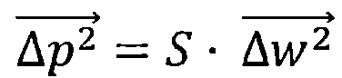
在提供該等粒子光學組件效果的該第一設定之處理之後,該粒子光學單元設定為一成像粒子光學單元。然後該方法更進一步包含決定一線性或非線性算術映射,其描述該等粒子光學組件效果改變之間的關係,例如考量透過線圈或電極上電壓的電流改變,以及將該粒子光學成像特徵化的該等參數改變,例如該成像比例或收斂。根據具體實施例,利用矩陣A可說明線性案例中的這種關係,以使以下為真:


其中


根據具體實施例,該矩陣A可由實驗決定。藉由出自於該等粒子光學組件效果第一設定之範例,獨立效果可改變並且可利用例如測量,決定將該粒子光學成像特徵化的該等參數之改變結果。 According to a specific embodiment, the matrix A can be determined experimentally. With the example from the first setting of the effects of the particle optical components, the independent effects can be changed and the results of the changes of the parameters that characterize the particle optical imaging can be determined using, for example, measurement.
其可進行m×n測量,以便決定該矩陣A的該等m×n項目:針對該等m個參數之每一者,該等n個粒子光學組件已經改變,並且在每一案例中決定該等組件在該相關參數上的每一改變之影響。這針對所有參數來執行。針對每一參數,此導致等式數量等於粒子光學組件數量。在此案例中,該等粒子光學組件的改變必須受到影響,使得出現等式的線性無關系統。從所有該等參數的等式來說,用此方式出現該矩陣A的所有分量。以算術方式表示,在針對該矩陣A的該等m列向量a i1、a i2、...、a in (i=1、...、m)每一者之該等n測量每一者內,n等式的數量產生,其可關於該列向量a i1、a i2、...、a in(i=1、...、m)的該等元件來解出。也就是說,使用m×n測量可決定該矩陣A的所有矩陣元件。針對m不等於n的案例,產生等式的超定或欠定系統。不過,這並不會造成該方法的下一步驟中有任何限制。 It can perform m × n measurements in order to determine the m × n items of the matrix A : for each of the m parameters, the n particle optical components have changed, and the decision is made in each case The effect of each change of the relevant components on the relevant parameters. This is performed for all parameters. For each parameter, this results in the number of equations equal to the number of particle optics. In this case, the changes of the particle optical components must be affected, so that a linearly independent system of equations appears. From the equation of all such parameters, all components of the matrix A appear in this way. Expressed in an arithmetic manner, the n measurements of each of the m column vectors a i 1 , a i 2 , ..., a in ( i =1, ..., m ) for the m columns of the matrix A Within one, the number of n equations is generated, which can be solved with respect to the elements of the column vectors a i 1 , a i 2 , ..., a i n ( i =1, ..., m ) . That is to say, using m × n measurement can determine all matrix elements of the matrix A. For cases where m is not equal to n , an overdetermined or underdetermined system of equations is produced. However, this does not cause any restrictions in the next step of the method.
藉由範例,在最簡單的案例中,決定該矩陣A可包含產生與該第一設定不同的設定,如此只有該向量
依照本說明書內的具體實施例,決定該矩陣A更進一步包含重複產生與該第一設定不同的該設定之處理,其中每次只有一個與該向量


根據進一步具體實施例,決定該矩陣A包含數值模擬該粒子光學成像,如此根據該數值模擬,決定在該等粒子光學組件效果改變事件中所帶來將該成像特徵化的參數內之改變。 According to a further specific embodiment, it is determined that the matrix A includes a numerical simulation of the particle optical imaging, and thus, based on the numerical simulation, a change in the parameters that characterize the imaging in the event of an effect change of the particle optical components is determined.
該等粒子光學組件可包含粒子光學透鏡,其可設定的效果為聚焦效果、像差補償器,其可設定的效果為像散效應,以及其他粒子光學組件及這些的組合。 The particle optical components may include particle optical lenses whose settable effects are focusing effects, aberration compensators, and whose settable effects are astigmatism effects, and other particle optical components and combinations thereof.
根據具體實施例,一粒子光束系統包含:一多光束來源,其設置用於產生複數個第一粒子束的一第一場;一第一粒子光學單元,其設置用於將該等第一粒子束指引到一物體上;以及一控制器;其中該第一粒子光學單元包含至少兩個,尤其是三個或四個粒子光學透鏡,這些透鏡都排列在該第一粒子光學單元的一光束路徑內;其中該控制器設置成用於設定該等第一粒子束上該第一粒子光學單元的該等粒子光學透鏡之每一者之效果,如此含該等第一粒子束粒子的一第一平面以粒子光學方式成像到一第二平面上,並且該第二平面與一物體平面重疊,如此該等第一粒子束在位於一第二場的一撞擊位置上撞擊該物體。 According to a specific embodiment, a particle beam system includes: a multi-beam source configured to generate a first field of a plurality of first particle beams; a first particle optical unit configured to use the first particles The beam is directed to an object; and a controller; wherein the first particle optical unit includes at least two, especially three or four particle optical lenses, these lenses are arranged in a beam path of the first particle optical unit Inside; wherein the controller is configured to set the effect of each of the particle optical lenses of the first particle optical unit on the first particle beams, such a first containing the first particle beam particles The plane is imaged onto a second plane by particle optics, and the second plane overlaps with an object plane, so that the first particle beams strike the object at an impact position in a second field.
用於該粒子束系統內的該第一粒子光學單元首先允許一設 定,如此該第一平面與該第二平面間之距離可設定,如此若例如以相對固定於該第一粒子光學單元來定位該第一平面並且該物體排列在與該第一平面相距一已知距離,則該第二平面可設定成其排列在該物體上,並且與例如該物體的表面重疊。該第一粒子光學單元第二允許將該粒子光學成像特徵化的進一步參數設定為所要值,該等參數特別包含該成像比例、該旋轉以及該光束路徑收斂,其中這些參數可用彼此特別獨立的方式來設定。這表示例如該成像比例可在該光束路徑收斂以及該旋轉不變之下改變,或該旋轉可在該成像比例以及該光束路徑收斂不變之下改變。 The first particle optical unit used in the particle beam system first allows a design In this way, the distance between the first plane and the second plane can be set, so if, for example, the first plane is positioned relatively fixed to the first particle optical unit and the objects are arranged at a distance from the first plane Knowing the distance, the second plane can be set so that it is arranged on the object and overlaps with, for example, the surface of the object. The first particle optical unit second allows further parameters characterizing the particle optical imaging to be set to the desired values, these parameters including in particular the imaging scale, the rotation and the beam path convergence, wherein these parameters can be used in a way that is particularly independent of each other To set. This means that, for example, the imaging ratio can be changed without converging the beam path and the rotation, or the rotation can be changed without converging the imaging ratio and the beam path.
根據具體實施例,設置多光束來源,如此所產生的光束從安排在彼此相距一距離的位置上通過該第一平面,並且在該第一平面內定義該第一場。這些位置可定位在每一案例中彼此相距一樣距離的該場內。更進一步,該等位置可形成矩形方格或六角形方格。尤其是,該等位置之間的距離可固定,也就是不可改變。該第一平面內的這些位置由該等粒子束成像至該第二平面內位置上或該物體上,其上該等粒子束通過該第二平面或撞擊該物體。在該第二平面或該物體上,這些位置形成該第二場,其以粒子光學方式對應至該第一場,其中該第二場內該等位置間之距離取決於該粒子光學成像之該成像比例。根據具體實施例,該控制器設置成利用改變該第一粒子光學單元的該等粒子光學透鏡之效果,來改變該成像比例以及因此改變該第二場之內該等撞擊位置間之距離。 According to a specific embodiment, a multi-beam source is provided, the beams thus generated pass through the first plane from a position arranged at a distance from each other, and the first field is defined in the first plane. These positions can be located in the field at the same distance from each other in each case. Furthermore, these positions can form a rectangular grid or a hexagonal grid. In particular, the distance between these locations can be fixed, that is, cannot be changed. The positions in the first plane are imaged by the particle beams to positions in the second plane or to the object, on which the particle beams pass through the second plane or strike the object. On the second plane or the object, these positions form the second field, which corresponds to the first field in a particle optical manner, wherein the distance between the positions in the second field depends on the particle optical imaging Imaging ratio. According to a specific embodiment, the controller is configured to use the effect of changing the particle optical lenses of the first particle optical unit to change the imaging scale and thus the distance between the impact locations within the second field.
該第二平面內或該物體上該第二場的方位取決於該粒子光學成像之旋轉。根據具體實施例,該控制器進一步設置成利用改變該第一粒子光學單元的該等粒子光學透鏡之效果,來改變該旋轉以及因此改變撞 擊位置的該第二場相對於該等粒子光學透鏡之方位。 The orientation of the second field in the second plane or on the object depends on the rotation of the particle optical imaging. According to a specific embodiment, the controller is further arranged to use the effect of changing the particle optical lenses of the first particle optical unit to change the rotation and therefore the collision The second field of the impact position is relative to the orientation of the particle optical lenses.
該控制器更進一步設置成利用改變該第一粒子光學單元的該等粒子光學透鏡之效果,不改變該處理中撞擊位置的該第二場相對於該等粒子光學透鏡之該方位,來改變該第二場之內該等撞擊位置間之距離。 The controller is further configured to use the effect of changing the particle optical lenses of the first particle optical unit without changing the orientation of the second field of the impact position in the process relative to the particle optical lenses to change the The distance between these impact locations within the second field.
該控制器有可能設置成利用改變該第一粒子光學單元的該等粒子光學透鏡之效果,不改變該處理中該第二場之內該等撞擊位置間之距離,來改變撞擊位置的該第二場相對於該等粒子光學透鏡之該方位。 The controller may be set to change the first position of the impact position without changing the distance between the impact positions within the second field in the process by changing the effect of the particle optical lenses of the first particle optical unit The orientation of the two fields relative to the particle optical lens.
根據具體實施例,該粒子光束系統另包含:一偵測器,其具有排列在一第三場內的複數個偵測區;一第二粒子光學單元,其設置成將從該物體上撞擊位置的該第二場內該等撞擊位置冒出之第二粒子束引導至偵測區域的該第三場上;其中該第二粒子光學單元包含至少兩個,尤其是三個或四個粒子光學透鏡,這些透鏡都排列在一第三平面與一第四平面之間該第二粒子光學單元的一光束路徑內。該控制器設置成將該第二粒子光學單元的該等粒子光學透鏡每一者之效果設定到該第二粒子束上,如此該第三平面成像於該第四平面上。在此案例中,該第三平面可與該物體的該表面重疊,並且偵測區的該場可排列在該第四平面內,如此該等第二粒子束每一者都撞擊排列在該第三場內至少該等偵測區之一者上,互不相同的第二粒子束撞擊到互不相同的偵測區。 According to a specific embodiment, the particle beam system further includes: a detector having a plurality of detection areas arranged in a third field; and a second particle optical unit configured to strike a position from the object The second particle beam emerging from the impact position in the second field is directed to the third field of the detection area; wherein the second particle optical unit includes at least two, especially three or four particle optics Lenses, these lenses are arranged in a beam path of the second particle optical unit between a third plane and a fourth plane. The controller is configured to set the effect of each of the particle optical lenses of the second particle optical unit onto the second particle beam, so that the third plane is imaged on the fourth plane. In this case, the third plane may overlap with the surface of the object, and the field of the detection area may be arranged in the fourth plane, so that each of the second particle beams collides and is arranged in the first In at least one of the detection areas in the three fields, different second particle beams impinge on different detection areas.
此粒子束系統可操作為一粒子束顯微鏡,其同時在該物體的複數個位置上執行該物體屬性測量。 The particle beam system can be operated as a particle beam microscope, which simultaneously performs the property measurement of the object at a plurality of positions of the object.
該第二粒子控制單元設置成如此首先該第三平面與該第一粒子光學單元的該第二平面或該物體的表面重疊,並且該第三平面藉由該 等第二粒子束從該第三平面進入該第四平面來成像,該第四平面內排列偵測區的該第三場。第二,該第二粒子光學單元可設置成設定該成像的進一步參數,例如該成像比例、該旋轉以及該光束路徑的收斂。考慮到該成像比例的可設定度,如此在已知該等偵測區之間距離並且該第二平面內該等第一粒子束的該等撞擊位置間之距離可變之下,可藉由該等第二粒子束將該獨立撞擊位置成像在對應的偵測區域上。 The second particle control unit is set such that first the third plane overlaps with the second plane of the first particle optical unit or the surface of the object, and the third plane passes the After the second particle beam enters the fourth plane from the third plane for imaging, the third field of the detection area is arranged in the fourth plane. Second, the second particle optical unit can be set to set further parameters of the imaging, such as the imaging scale, the rotation, and the convergence of the beam path. Considering the settable degree of the imaging scale, under such a known distance between the detection areas and the distance between the impact positions of the first particle beams in the second plane is variable, the The second particle beams image the independent impact position on the corresponding detection area.
有可能並非所有該等參數都與該多束粒子系統的特定操作模式有關,有可能例如該第二粒子光學單元內該光束路徑的收斂與該旋轉或該成像比例較無關係。然後較少的粒子光學組件就足夠設定所要的剩餘參數。例如若衍射平面的該位置要故意維持基本上恆定,則可針對在該衍射平面的該位置上具有高決定影響的特定透鏡,預先選擇並決定一固定激勵。 It is possible that not all of these parameters are related to the specific operating mode of the multi-beam particle system, and it is possible that, for example, the convergence of the beam path in the second particle optical unit has little to do with the rotation or the imaging scale. Then fewer particle optics are enough to set the remaining parameters required. For example, if the position of the diffraction plane is intentionally kept substantially constant, a fixed excitation can be pre-selected and decided for a specific lens having a high decision influence at the position of the diffraction plane.
根據具體實施例,該控制器更進一步設置成利用改變該第二粒子光學單元的該等粒子光學透鏡之效果,補償該第二場之內該等撞擊位置之間距離的改變,如此在該第二場之內該撞擊位置之間該等距離改變的事件中,撞擊至少該等偵測區之一者的每一該第二粒子束都排列在該第三場內,並且互不相同的第二粒子束撞擊在互不相同的偵測區域上。 According to a specific embodiment, the controller is further configured to use the effect of changing the particle optical lenses of the second particle optical unit to compensate for the change in the distance between the impact positions within the second field. In the event that the distances between the impact positions change within the two fields, each of the second particle beams striking at least one of the detection areas is arranged in the third field, and the mutually different The two particle beams hit different detection areas.
根據本說明書中的示範具體實施例,該控制器更進一步設置成利用改變該第二粒子光學單元的該等粒子光學透鏡之效果,補償撞擊位置的該第二場相對於該第二粒子光學單元的該等粒子光學透鏡之方位改變,如此在撞擊位置的該第二場方位改變之事件中,撞擊至少該等偵測區之一者的每一該等第二粒子束都排列在該第三場內,並且互不相同的第二 粒子束撞擊在互不相同的偵測區域上。 According to an exemplary embodiment in this specification, the controller is further configured to compensate for the second field of the impact position relative to the second particle optical unit using the effect of changing the particle optical lenses of the second particle optical unit The orientation of the particle optical lenses of the is changed, so that in the event of an orientation change of the second field of the impact position, each of the second particle beams striking at least one of the detection areas is arranged in the third Second in the field and different from each other The particle beam hits different detection areas.
該等第一和第二粒子光學單元可具體實施為無共用粒子光學透鏡的個別粒子光學單元。不過,也可能該第一粒子光學單元的該等至少二個,尤其是三個或四個粒子光學透鏡的至少一個粒子光學透鏡為該第二粒子光學單元的該等至少二個,尤其是三個或四個粒子光學透鏡的至少、之一者,如此該等第一和第二粒子光學單元具有一個或複數個共用透鏡。該等至少一個共用透鏡可為例如一粒子光學顯微鏡的一物鏡。根據本說明書中的具體實施例,該粒子束系統包含一粒子光學開關,其排列在該等第一和第二粒子光學單元的該等光束路徑內。 The first and second particle optical units may be embodied as individual particle optical units without a shared particle optical lens. However, it is also possible that at least two of the first particle optical units, especially at least one particle optical lens of three or four particle optical lenses are at least two of the second particle optical units, especially three At least one of the one or four particle optical lenses, so that the first and second particle optical units have one or a plurality of common lenses. The at least one common lens may be an objective lens of a particle optical microscope, for example. According to a specific embodiment in this specification, the particle beam system includes a particle optical switch arranged in the beam paths of the first and second particle optical units.
1‧‧‧粒子光學單元 1‧‧‧Particle optical unit
1‧‧‧檢測系統 1‧‧‧ detection system
2‧‧‧粒子光學透鏡 2‧‧‧Particle optical lens
3‧‧‧粒子光學透鏡、電子束 3‧‧‧Particle optical lens, electron beam
4‧‧‧粒子光學透鏡 4‧‧‧Particle optical lens
5‧‧‧位置、粒子光學透鏡 5‧‧‧Position, particle optical lens
7‧‧‧光學軸、物體 7‧‧‧Optical axis, object
9‧‧‧控制器 9‧‧‧Controller
9‧‧‧電子束 9‧‧‧ electron beam
13‧‧‧第一平面 13‧‧‧The first plane
15‧‧‧第二平面 15‧‧‧Second plane
15’‧‧‧第二平面 15’‧‧‧second plane
17‧‧‧箭頭 17‧‧‧arrow
19‧‧‧場射線 19‧‧‧ field rays
21‧‧‧箭頭 21‧‧‧arrow
23‧‧‧直角 23‧‧‧Right angle
37‧‧‧場 37‧‧‧
39‧‧‧部分場 39‧‧‧Partial
41‧‧‧參考標記 41‧‧‧Reference mark
42‧‧‧參考標記 42‧‧‧Reference mark
43‧‧‧參考標記 43‧‧‧Reference mark
44‧‧‧參考標記 44‧‧‧Reference mark
45‧‧‧水平編碼區 45‧‧‧ horizontal coding area
46‧‧‧垂直編碼區 46‧‧‧Vertical coding area
47‧‧‧測試圖案 47‧‧‧Test pattern
51‧‧‧參考檯 51‧‧‧Reference station
53‧‧‧測量探針 53‧‧‧Measurement probe
55‧‧‧參考表面 55‧‧‧Reference surface
55’‧‧‧參考表面 55’‧‧‧Reference surface
55”‧‧‧參考表面 55”‧‧‧Reference surface
57‧‧‧移動台 57‧‧‧Mobile
59‧‧‧致動器 59‧‧‧Actuator
61‧‧‧樣本室 61‧‧‧Sample room
63‧‧‧樣本檯 63‧‧‧Sample table
65‧‧‧樣本 65‧‧‧sample
100‧‧‧物鏡系統 100‧‧‧Objective system
101‧‧‧物體平面 101‧‧‧Object plane
102‧‧‧物鏡 102‧‧‧Objective
103‧‧‧一般矩形場 103‧‧‧General rectangular field
104‧‧‧校正物體 104‧‧‧corrected object
200‧‧‧偵測系統 200‧‧‧detection system
205‧‧‧投影透鏡系統 205‧‧‧Projection lens system
209‧‧‧電子多重偵測器 209‧‧‧Electronic multiple detector
211‧‧‧平面 211‧‧‧plane
213‧‧‧位置 213‧‧‧ Location
217‧‧‧第二場
217‧‧‧
300‧‧‧光束產生裝置 300‧‧‧beam generating device
301‧‧‧電子來源 301‧‧‧Electronic source
303‧‧‧準直透鏡 303‧‧‧collimating lens
305‧‧‧多孔徑配置 305‧‧‧Multi-aperture configuration
307‧‧‧場透鏡系統 307‧‧‧Field lens system
309‧‧‧發散電子束 309‧‧‧ Divergent electron beam
311‧‧‧光束 311‧‧‧beam
313‧‧‧多孔徑平板 313‧‧‧Multi-aperture flat plate
315‧‧‧開口 315‧‧‧ opening
317‧‧‧中點 317‧‧‧ midpoint
319‧‧‧場 319‧‧‧
323‧‧‧光束焦點 323‧‧‧beam focus
325‧‧‧平面 325‧‧‧plane
400‧‧‧光束開關 400‧‧‧beam switch
403‧‧‧調整透鏡 403‧‧‧Adjust lens
下面將參考圖式來更詳細說明本發明的具體實施例,其中:圖1顯示一傳統粒子束系統;圖2a、圖2b和圖2c顯示根據本發明的一個粒子束系統具體實施例內之成像示意圖;圖3顯示用於闡明一個粒子光學單元操作方法具體實施例的流程圖;圖4、圖5和圖6在逐漸放大的例圖中顯示一個測試圖案具體實施例;圖7至圖13顯示測試圖案的變化;以及圖14a、圖14b和圖14c顯示一物鏡、一測量系統以及一校正物體的剖面圖來闡明一調整技術。 The specific embodiments of the present invention will be described in more detail below with reference to the drawings, in which: FIG. 1 shows a conventional particle beam system; FIGS. 2a, 2b, and 2c show imaging in a specific embodiment of a particle beam system according to the present invention. Schematic diagram; FIG. 3 shows a flow chart for explaining a specific embodiment of a particle optical unit operating method; FIGS. 4, 5 and 6 show a specific embodiment of a test pattern in the gradually enlarged example diagram; FIGS. 7 to 13 show Changes in test patterns; and Figures 14a, 14b, and 14c show a cross-sectional view of an objective lens, a measurement system, and a calibration object to illustrate an adjustment technique.
圖1為使用複數個粒子束的多束檢測系統之示意圖。該檢測系統產生複數個粒子束,撞擊在要試驗的物體上,以便在此產生電子,這
些電子從該物體發出並接著被偵測到。檢測系統1為一種掃描式電子顯微鏡(SEM,scanning electron microscope),其使用複數個主要電子束3撞擊物體7表面上位置5,並且在此產生複數個電子束點。要試驗的物體7可為任意類型,並且包含例如一半導體晶圓、一生物樣本以及小型化元件的配置等等。物體7的該表面排列在一物鏡系統100的物鏡102之物體平面101內。
FIG. 1 is a schematic diagram of a multi-beam detection system using a plurality of particle beams. The detection system generates a plurality of particle beams that impinge on the object to be tested to generate electrons here, which
Some electrons are emitted from the object and then detected. The
圖1內的放大摘錄I1顯示物體平面101的平面圖,內含形成於平面101內的撞擊位置5之一般矩形場103。在圖1內,撞擊位置的數量為25,排列成一5×5場103。為了簡化起見,所以選擇撞擊位置數25這小數量。尤其是,粒子束或撞擊位置的數量可選擇大一點,像是例如20×30、100×100等。
The enlarged excerpt I1 in FIG. 1 shows a plan view of the
在例示的具體實施例內,撞擊位置5的場103大體上為一般矩形場,在相鄰撞擊位置之間具有恆定距離P1。距離P1的示範值為1μm、10μm或40μm。不過,場103也可具有其他對稱性,像是例如六角對稱。
In the illustrated specific embodiment, the
在物體平面101內形成的粒子束點直徑並不大,此直徑的示範值為1nm、5nm、100nm和200nm。利用物鏡系統100執行用於形成粒子束點5的粒子束3之聚焦。
The diameter of the particle beam spot formed in the
該等粒子撞擊該物體,產生電子從物體7的表面冒出。從物體7表面冒出的該等電子由物鏡102塑型來形成電子束9。檢測系統1提供一電子束路徑11,以便將多個電子束9送至偵測系統200。偵測系統200包含具有投影透鏡系統205的一電子光學單元,以便將電子束9導引至電子多重偵測器209上。
The particles hit the object, producing electrons emerging from the surface of the object 7. The electrons emerging from the surface of the object 7 are shaped by the
圖1內的摘錄I2顯示平面211的平面圖,其中排列個別偵測區,其上電子束9撞擊位置213。撞擊位置213形成一第二場217,在該等撞擊位置之間具有規則距離P2,距離P2的示範值為10μm、100μm或200μm。
The excerpt I 2 in FIG. 1 shows a plan view of the
光束產生裝置300內產生主要電子束3,該裝置包含至少一個電子來源301、至少一個準直透鏡303、一個多孔徑配置305以及一個場透鏡系統307。電子來源301產生一發散電子束309,其利用準直透鏡303準直,以便塑造光束311照射多孔徑配置305。
The
圖1內的摘錄I3顯示多孔徑配置305的平面圖。多孔徑配置305包含一多孔徑平板313,其內形成複數個開口或孔徑315。開口315的中點317配置在一場319內,其對應至物體平面101內光束點5所形成的場103。孔徑315的中點317間之距離P3可具有5μm、100μm和200μm的示範值。孔徑315的直徑D小於該等孔徑中點間之距離P3,直徑D的示範值為0.2×P3、0.4×p3和0.8×P3。
Excerpt I3 in FIG. 1 shows a plan view of the
照射束311的電子通過孔徑315,並形成電子束3。該晶格會捕捉入射平板313的照射束311之電子,因此不會用於形成電子束3。
The electrons irradiating the
多孔徑配置305將電子束3聚焦,如此在平面325內形成光束焦點323。焦點323的直徑可為10nm、100nm和1μm。
The
場透鏡系統307和物鏡102提供用於將平面325成像的一第一成像粒子光學單元,其中該焦點形成於物體平面101上,如此在物體7的表面上形成撞擊位置5的一場103或光束點。
The
物鏡102和投影透鏡系統205提供一第二成像粒子光學單
元,用於將物體平面101成像至偵測平面211上。如此,物鏡102是一個同時為第一粒子光學單元零件以及第二粒子光學單元零件的透鏡,而場透鏡系統307只屬於該第一粒子光學單元,並且投影透鏡系統205只屬於該第二粒子光學單元。
光束開關400提供於多孔徑配置305與物鏡系統100之間該第一粒子光學單元之該光束路徑內。光束開關400也是物鏡系統100與偵測系統200之間該光束路徑內該第二粒子光學單元之零件。
The
光束開關400構成一非旋轉對稱電子光學成像系統。針對在主要光束路徑13內此粒子光學單元400之成像效能,最重要是該主要光束路徑內的該等粒子以正確入射角以及正確入射位置,通過該粒子光學單元。在此意義上,正確意味著入射角以及入射位置的偏差偏離數值模擬內所使用值足夠小之程度。不過,在考慮到其非旋轉對稱構造,光束開關400不提供用於決定該入射位置與入射角的直接標準。用於決定這些俗稱入射條件的直接可能性為例如將孔徑導入至該光束開關的該光束路徑上游,該等孔徑為可調整,相對於該光束開關的扇形場來說非常精準。因為考量到廣泛的成像場,該等孔徑不應固定安裝在該光束開關的上游,而是應該可藉由機械光圈驅動伸縮,該等孔徑的使用並非總是可用於空間因素。在此情況下,在光束產生裝置300與光束開關400之間插入一調整透鏡403(請參閱圖1)具有其優點。該調整透鏡403至少由一線圈以及選擇性一透鏡軛所構成,這兩者都可用機械方式非常精準地與光束開關400匹配。也就是說,該線圈關於光束開關400的該位置公差非常小。例如藉由電子光學模擬,可決定調整透鏡403相關於光束開關400的確切機械位置。在該粒子
光學系統的正常操作期間,該調整透鏡的該線圈關閉。在調整操作中,藉由偏轉器(未顯示)可設定光束產生裝置300的該光束路徑下游,如此在調整透鏡403的該激勵改變之事件中及/或在調整透鏡403的極性反轉之事件中,主要光束13並不會飄移。在此情況下,確定該主要光束撞擊調整透鏡403的中央,並且與該調整透鏡的光學軸平行運行。考量到調整透鏡403相關於該光束開關的匹配,因此確定該光束開關內的入射位置與入射角度足夠精準,在來自該模擬的該等值之公差範圍(誤差預算)之內。
The
從國際專利申請案WO 2005/024881、WO 2007/028595、WO 2007/028596和WO 2007/060017當中,以及具有申請編號DE 10 2013 016 113.4和DE 10 2013 014 976.2的德國專利申請案當中,可獲得本文內所使用有關這種多光束檢測系統以及組件的進一步資訊,例如粒子來源、多孔徑平板以及透鏡,這些申請案的完整揭露事項都在此併入當成本申請案的參考。 Available from international patent applications WO 2005/024881, WO 2007/028595, WO 2007/028596 and WO 2007/060017, and German patent applications with application numbers DE 10 2013 016 113.4 and DE 10 2013 014 976.2 Further information about this multi-beam detection system and components used in this article, such as particle sources, multi-aperture plates, and lenses, the full disclosure of these applications are here incorporated by reference as cost applications.
該第一粒子光學單元將第一平面325的粒子光學成像提供至第二平面101內。用於將該粒子光學成像特徵化的一個參數為沿著該光束軸,介於第一平面325與第二平面101之間的該距離。此距離可變,例如利用改變場透鏡系統307的影響或透鏡102的影響。用於將該粒子光學成像特徵化的進一步參數為該旋轉,憑藉由磁場所產生的透鏡307和102之效果所產生。磁場導致旋轉,如此該等個別粒子束不會沿著該光束路徑直線移動,而是沿著螺旋路徑移動。
The first particle optical unit provides particle optical imaging of the
圖1顯示例如該等撞擊位置的場103之所要方位,如此撞擊位置沿著圖1內水平與垂直線排列。此方位的值由圖1內的該角度R0所設
計,考量到該第一粒子光學單元所提供的該粒子光學成像之旋轉,該等粒子束的場必須具有一方位,如此該粒子束在通過該第一粒子光學單元之後,撞擊平面101形成具有該方位R0的一場。該等已產生粒子束的場319之必要方位由圖1內的該角度R1所表示。
FIG. 1 shows, for example, the desired orientation of the
該第二粒子光學單元也提供一粒子光學成像,其可具有介於平面101與211之間的該距離當成一特徵化參數。更進一步,該旋轉也為將該第二粒子光學單元特徵化之參數。第二粒子束的場103來自於平面101並具有方位R0,在通過該第二粒子光學單元之後,以一方位,就圖1內該角度R2所指定,撞擊平面211。
The second particle optical unit also provides a particle optical imaging, which may have the distance between the
在圖1的示意圖中,個別粒子束3、9的主要射線都垂直通過平面325、101和211。這種光束路徑指定為一遠心光束路徑,實際上有其優點,因為例如改變物體7與物鏡102之間的距離會導致該物體上該光束點放大,但是不會改變該等光束點之間的該距離P1。不過,在該第一及/或第二粒子光學單元的該粒子光學透鏡之效果已改變的案例中,該光束路徑的收斂改變,也就是說,例如與物鏡102的光學軸相距一段距離運行的粒子束3之主要射線不再垂直撞擊平面101。
In the schematic diagram of FIG. 1, the main rays of the
圖2a為一粒子光學單元1的示意圖,該單元包含四個粒子光學透鏡2、3、4和5,這些都沿著粒子光學單元1的光學軸7排列。透鏡2、3、4、5具體實施為磁性透鏡,其線圈由控制器9供應激勵電流,產生透鏡的磁場,其中該激勵電流可針對每一透鏡調整,如圖2a內用箭頭9圖解代表可設定的激勵電流。透鏡2、3、4、5之間沿著光學軸7的距離通常藉由透鏡的設計來固定,也就是說在操作期間不可改變。不過,利用改變
該等透鏡在一粒子束上的效果,藉由該控制器9將可設定的激勵電流供應給個別透鏡,則可由控制器9改變該粒子光學單元的光學特性。
FIG. 2a is a schematic diagram of a particle
粒子光學單元1以粒子光學方式將一第一平面13成像至一第二平面15內,這兩平面沿著光學軸7彼此相隔一距離。在圖2a的示意圖中,此成像由配置在第一平面13內的箭頭17,以及將箭頭17成像至配置在第二平面15內的箭頭21之粒子束主要射線的兩場射線19所呈現。
The particle
此成像可由四個參數特徵化:第一參數為第一平面13與第二平面15之間沿著光學軸7的距離,第二參數為該成像的該成像比例,其來自於箭頭21與17的長度比例,第三參數為該旋轉,來自於針對箭頭17的已知方位繞著光學軸7旋轉,造成箭頭21的方位繞著光學軸7旋轉,在圖2a內,箭頭17的方位用一角度R呈現,並且箭頭21的方位用一角度R1呈現,第四參數為該光束路徑的收斂,來自於場射線19與光學軸7相距一已知距離,以一角度通過平面13和15,在圖2a內,其可為平面13上的直角23以及平面15上的直角T1,如此該成像為遠心。
This imaging can be characterized by four parameters: the first parameter is the distance between the
此時應該假設由粒子光學單元1參考圖2a描述的該粒子光學成像要改變,特別是如此會提高該成像比例。為此,該控制器根據圖2a,修改透鏡2、3、4和5的效果之設定。
At this time, it should be assumed that the particle optical imaging described by the particle
圖2b顯示透鏡2、3、4和5與根據圖2a設定不同的效果設定,其中透鏡2、4和5的效果設定與根據圖2a的設定相同,只有透鏡3的設定與根據圖2a的設定不同。這首先導致該成像比例值增加,從圖2b內箭頭21的長度比圖2a中還要長可得到證明。不過,這也具有第一平面13成像至第二平面15’的效果,該第二平面與第一平面13相距一段距離,
該距離比根據圖2a的該設定情況中之對應距離要小一值△F。更進一步,箭頭21配置在平面15’內,具有與圖2a內該方位R 1不同之方位R 3。如此,該成像的旋轉已經由△R=R 3-R 1所改變。
Figure 2b shows the different effect settings for
更進一步,圖2b內的場射線19以一角度T3撞擊平面15’,如此相較於根據圖2a的該設定,該光束路徑的遠心度或收斂可能改變,其中該光束路徑收斂的改變值可顯示為△T=T 3-T 1。
Still further change the value of field rays in FIG.
這顯示在一粒子光學單元內只有一個粒子光學組件之效果改變,會導致將該粒子光學單元所提供的該粒子光學成像特徵化之四個參數改變。 This shows that the change in the effect of only one particle optical component in a particle optical unit will cause the four parameters that characterize the particle optical imaging provided by the particle optical unit to change.
不過實際上,吾人想要改變一粒子光學單元的設定,如此由於該設定改變結果,只有將該粒子光學成像特徵化的一個參數改變,其他參數保留未變。為此,需要改變複數個粒子光學組件的效果設定一起改變。不過難以決定為了達成此目標,決定該個別粒子光學組件的效果值之必要改變。實際上,這傳統上通常反覆執行。 However, in reality, we want to change the setting of a particle optical unit. Therefore, due to the result of this setting change, only one parameter that characterizes the particle optical imaging is changed, and the other parameters remain unchanged. For this reason, it is necessary to change the effect settings of a plurality of particle optical components together. However, it is difficult to determine the necessary changes to determine the effect value of the individual particle optics in order to achieve this goal. In fact, this has traditionally been repeated over and over.
底下參考圖3,說明一粒子光學單元的粒子光學組件效果之設定方法範例,如此該等參數將具有所要值的該成像特徵化。在此情況下,該方法的起點為步驟51,在此提供該粒子光學組件的效果之第一設定,如此一第一平面成像至一第二平面。該第一設定內該個別粒子光學組件的效果值由一向量來呈現,將該成像特徵化的該等參數之值可由一向量來呈現。
Next, referring to FIG. 3, an example of a method for setting the particle optical element effect of a particle optical unit will be described, so that these parameters will characterize the imaging with desired values. In this case, the starting point of the method is
此時應想要修改該粒子光學組件的效果之該第一設定,如此在一第二設定內,將具有所要值的該成像特徵化之該等參數由一對應向量
為此,在步驟53內,已經決定一矩陣A,以使以下為真:


在此


該矩陣A可例如由數值模擬來決定,或在該粒子光學單元本身上用實驗來決定,利用其中已改變的設定由改變該個別粒子光學組件效果值來進行之程序,並且將該等粒子光學成像特徵化的該等參數內之結果變化由測量所決定。 The matrix A can be determined, for example, by numerical simulation, or experimentally on the particle optical unit itself, using a procedure in which the changed settings are performed by changing the effect value of the individual particle optical component, and the particle optical The changes in the results within these parameters characterized by imaging are determined by measurements.
其可進行m×n測量,以便決定該矩陣A的該等m×n項目:針對該等m個參數之每一者,該等n個粒子光學組件已經改變,並且在每一案例中決定該等組件在該相關參數上的每一改變之影響。這針對所有參數來執行。針對每一參數,此導致等式數量等於粒子光學組件數量。 It can perform m × n measurements in order to determine the m × n items of the matrix A : for each of the m parameters, the n particle optical components have changed, and the decision is made in each case The effect of each change of the relevant components on the relevant parameters. This is performed for all parameters. For each parameter, this results in the number of equations equal to the number of particle optics.
底下解釋一範例,其中將該成像特徵化的該等參數為該收斂、該旋轉以及該成像比例,如此該數為m=3,△tele、△rot和△mag依序代表這些參數的改變。在此範例中,該成像由四個透鏡所提供,如此粒子光學組件的數量為n=4。電流I產生該等透鏡的效果。 An example is explained below, in which the parameters characterizing the imaging are the convergence, the rotation, and the imaging scale, so that the number is m = 3, and △ tele , △ rot, and △ mag represent the changes of these parameters in order. In this example, the imaging is provided by four lenses, so the number of particle optics is n = 4. The current I produces the effect of such lenses.
該

其中該等參數△tele、△rot和△mag內的結果改變以三種測量方式測量。該矩陣的分量a ij 一開始未知。設定n=4的總數與該等電流△I i的變化不同,並且在該四個設定之每一者內測量該等參數△tele、△rot和△mag的三種變化,如此要執行總共12次測量。 Among these parameters, the changes in the results of △ tele , △ rot and △ mag are measured by three measurement methods. The components a ij of the matrix are initially unknown. The total number of settings n = 4 is different from the changes of these currents △ I i , and the three changes of these parameters △ tele , △ rot and △ mag are measured in each of the four settings, so a total of 12 times are performed measuring.
然後,該等值a 11、...、a 14可由該第一參數△tele的該等改變之設定來決定

其中上標字指出該等電流變化數量。此等式可用a 11、...、a 14來解出,結果獲得該矩陣A的第一列之元素。然後,一對應程序調整用於△rot和△mag,以便計算該矩陣A的第二和第三列之元素,如此計算出該矩陣A的所有元素。對此,若該等電流的變化已經選取就有用,如此在上面的等式內,該列向量具有元素


在步驟53內已經決定一矩陣A之後,在步驟55內,決定一矩陣S,以使以下為真:S.A=D A , After a matrix A has been decided in
其中D A 唯一對角矩陣或幾乎是對角式的矩陣。若該等非對角元素顯著小於該等對角元素,則一矩陣就幾乎為對角式。若以數值計算該矩陣S並且該矩陣A為病態,則特別產生這種矩陣。在此案例中,特別是可能決定該矩陣S,如此S=A -1 D A is the only diagonal matrix or almost diagonal matrix. If the off-diagonal elements are significantly smaller than the diagonal elements, then a matrix is almost diagonal. If the matrix S is calculated numerically and the matrix A is ill-conditioned, such a matrix is particularly generated. In this case, in particular, the matrix S may be determined, so that S = A -1
為真,也就是說該矩陣S利用該矩陣A的顛倒來計算。然後,該矩陣D A 為單位矩陣或幾乎是單位矩陣,也就是說該矩陣D A 的該等對角元素只稍微差異1,並且該等非對角元素只稍微差異0。 Is true, that is to say the matrix S is calculated using the inverse of the matrix A. Then, the matrix D A is an identity matrix or almost an identity matrix, that is to say, the diagonal elements of the matrix D A differ only slightly by 1, and the non-diagonal elements differ only slightly by zero.
之後,在步驟57內定義將該所要成像特徵化之該等參數值。這些值可表示為一向量


如此由於該等式

更進一步,後續可執行進一步、不同的該等粒子光學組件之該等效果設定。為此,該方法可跳至步驟57,其中決定該等參數的所要值,
並且可在步驟59內執行該等新效果之設定,其中先前在步驟55內已經決
定的該對角矩陣D A 用於該計算。這很容易做到,尤其是若該向量
上面解釋的該方法可修改根據圖2a中透鏡2、3、4、5的該等效果之設定,如此只有該成像的該成像比例增加,該第一和第二平面之間的距離維持相同(△F=0),該旋轉維持相同(△R=R 2-R 1=0)並且該光束路徑的該收斂維持相同(△T=T 2-T 1=0)。圖2c內例示這種該等粒子光學組件,也就是透鏡2、3、4、5,的該等效果之設定。
The method explained above can modify the settings according to the effects of
上面已經參考圖2a、2b和2c並且根據一粒子光學單元,其使用四個透鏡將第一平面成像至第二平面,其中該等四個透鏡排列在這兩平面之間,來解釋設定一粒子光學單元的該方法。不過,該方法並不受限於此。可使用更多或更少的透鏡來提供該成像。一虛擬成像可實現,如此並非提供該成像的所有該等透鏡都需要排列在該兩平面之間,一或多個透鏡可排列在該第一平面的該光束路徑上游或該第二平面的光束路徑下游。更進一步,該成像可將該第一平面成像至一或多個中間成像平面,然後接著成像至該第二平面。更進一步,並不需要確實在該第一與第二平面之間形成一個交叉。而是可形成複數個交叉或完全不交叉。 2a, 2b and 2c have been referred to above and according to a particle optical unit, which uses four lenses to image the first plane to the second plane, where the four lenses are arranged between the two planes, to explain the setting of a particle The method of the optical unit. However, the method is not limited to this. More or fewer lenses can be used to provide this imaging. A virtual imaging can be achieved, so that not all the lenses providing the imaging need to be arranged between the two planes, one or more lenses can be arranged upstream of the beam path of the first plane or the beam of the second plane Path downstream. Furthermore, the imaging can image the first plane to one or more intermediate imaging planes, and then image to the second plane. Furthermore, it is not necessary to actually form a cross between the first and second planes. Instead, a plurality of intersections or no intersections at all can be formed.
吾人想要參考圖1解釋的該電子顯微鏡系統可操作,如此該
物體上粒子束3的相鄰撞擊位置間之該距離P1可設定,並且撞擊位置的該場之該方位R0可能可設定。為此,需要每一案例中的該第一和第二粒子光學單元設置成彼此獨立設定該成像比例與該旋轉,尤其較佳是如此不改變該光束路徑的收斂。這可由上面參考圖2a和圖3所解釋的方式來修改該第一和第二粒子光學單元來達成,這表示在圖1內對稱顯示的該等兩粒子光學單元每一者內排列四或更多個透鏡,這些透鏡可根據上面參考圖3所解釋的方法由一控制器控制。
I want the electron microscope system explained with reference to FIG. 1 to be operational, so that the distance P 1 between adjacent impact positions of the
底下解釋測試圖案,其可用來決定像是參考圖1所解釋的一多光束粒子光學單元之成像參數。例如藉由微影蝕刻方法,可在矽晶圓上高精準產生這種測試圖案。 The test pattern is explained below, which can be used to determine imaging parameters like a multi-beam particle optical unit explained with reference to FIG. 1. For example, by the lithography etching method, this test pattern can be generated on a silicon wafer with high precision.
從WO 2013/032949 A1可收集到有關用於多光束粒子系統的測試圖案之背景資訊,其在此完整併入當成本專利申請案之參考。 Background information on the test patterns used in multi-beam particle systems can be collected from WO 2013/032949 A1, which is hereby fully incorporated into the reference of the current cost patent application.
這些測試圖案較佳固定在也承載物體7的一移動桌面上,如此在該多光束粒子系統的操作期間,必要時該測試圖案可移動進入光束路徑9,以便實施該多光束粒子系統的測量、校正與調整。在該測量、校正與調整的結論之後,再次導入物體7並且繼續該物體的試驗。
These test patterns are preferably fixed on a moving table that also carries the object 7, so that during the operation of the multi-beam particle system, the test pattern can be moved into the
圖4顯示測試圖案31的一個範例。測試圖案31包含例如四個方形Q1、Q2、Q3和Q4以及例如四個調整標記33。該等方形Q1和Q2每一者都包含例如10×10=100小型場,而該等方形Q3和Q4每一者都包含例如7×7=49較大場。所有該等方形內的該等場在結構方面都是一致的測試圖案,底下有更詳細說明,但是尺寸有所差異。該等方形Q1和Q2的該等小型場提供用於測量具有12微米長度的粒子束之場,而該等方形Q3
和Q4的該等較大場提供用於測量具有18微米長度的粒子束之場。圖式內用黑白例示的該等測試圖案對應至該測試晶圓上的圖案,考量到其拓撲,也就是說例如考量到其表面的方位及/或考量到其結構,也就是說例如考量到其化學成分,導致在該記錄的二次電子影像中強烈對比。
FIG. 4 shows an example of the
圖5詳細顯示一個這種場37。其大約是六角輪廓,並且由127個部分場排列構成,其中圖5內的最頂端列包含七個部分場39。由上而下,每一案例中部分場39的數量逐列加一,直到中間列包含13個部分場。之後,每一案例中每列部分場39的數量逐列減一,直到圖5內最底列再度包含七個部分場。每一該等部分場都提供用於由粒子束場的一粒子束掃描。因為該場37內部分場39的配置對應至粒子束場內該等粒子束之配置。也就是說,粒子束場並未如圖1內所示排列成一矩形圖案,而是六角形圖案。
Figure 5 shows one
圖6顯示具有來自圖5的七個部分場39之放大摘錄。每一部分場39都包含參考標記41、42、43和44、水平編碼區45、垂直編碼區46以及一測試圖案47。在圖6內例示的範例中,在每一案例中,測試圖案47為四個巢狀方形群組。編碼區45細分成12個地區,例如每一地區都可或不可內含一編碼元素,例如像是一方形,如此每一編碼區都可編碼一數量。在此案例中,垂直區46編碼該場37內一特定部分場39所保有之數,並且水平區45編碼該等方形Q1、Q2、Q3和Q4之一者內一特定場37所保有之數。
FIG. 6 shows an enlarged excerpt with seven
圖7以放大圖顯示測試圖案47。該等個別線可具有例如60奈米的線寬。
FIG. 7 shows the
圖8至圖12顯示來自圖7的該測試圖案之變化。圖8內的該測試圖案由水平線構成,圖9內的該測試圖案由垂直線構成,圖10內的該測試圖案由交叉線構成,圖11內的該測試圖案由矩形方格配置構成,圖12內的該測試圖案由所有測試圖案內十字都遠離中央測試圖案(右側部分)所構成。該中央測試圖案進一步由一方形圍繞十字(左側部分)所構成。圖13內的該測試圖案為元素的非週期性圖案,其寬度由左至右並且由下至上以非線性方式改變。此測試圖案特別適合用於運用傅立葉轉換當成該成像處理步驟之測試。 8 to 12 show the change of the test pattern from FIG. 7. The test pattern in FIG. 8 is composed of horizontal lines, the test pattern in FIG. 9 is composed of vertical lines, the test pattern in FIG. 10 is composed of cross lines, and the test pattern in FIG. 11 is composed of a rectangular grid configuration. The test pattern in 12 is composed of all test patterns in which the cross is far from the central test pattern (right part). The central test pattern is further composed of a square surrounding the cross (left part). The test pattern in FIG. 13 is a non-periodic pattern of elements whose width changes in a non-linear manner from left to right and from bottom to top. This test pattern is particularly suitable for testing using Fourier transform as the imaging processing step.
上面解釋的該等測試圖案適合用於決定利用該粒子光學單元所提供的該成像所獲得之該成像比例以及該旋轉。例如設計為截頭金字塔的測試圖案適合用於決定該光束路徑的收斂,如此一截頭的金字塔具有四個大小一致的斜側面。在一粒子束垂直撞擊這種測試結構時,該等斜側面的尺寸似乎一致,而在歪斜撞擊粒子束的案例中,尺寸似乎不同。從該等斜側面的寬度測量當中,其可縮減該粒子束的撞擊角度,如此縮減其收斂度。 The test patterns explained above are suitable for determining the imaging scale and the rotation obtained by the imaging provided by the particle optical unit. For example, a test pattern designed as a truncated pyramid is suitable for determining the convergence of the beam path. Such a truncated pyramid has four oblique sides of uniform size. When a particle beam strikes this test structure perpendicularly, the dimensions of the oblique sides seem to be the same, while in the case of a skew impact particle beam, the dimensions seem to be different. From the width measurement of the oblique sides, it can reduce the angle of impact of the particle beam, thus reducing its convergence.
該測試晶圓的結構可運用在不同方式中來調整該等多光束設備,尤其是:該等粒子束的位置之決定、該等粒子束之間該距離的設定以及相對於該物體檯子的該多光束之相對方位、該遠心率,以便確定所有物體點都受到軸向平行束照射,該掃描的校正,以避免該掃描場扭曲與非線性,以及其他。 The structure of the test wafer can be used in different ways to adjust the multi-beam equipment, in particular: the determination of the position of the particle beams, the setting of the distance between the particle beams and the relative to the object table The relative azimuth of the multiple beams, the telecentricity, in order to determine that all object points are illuminated by the axial parallel beam, the correction of the scan, to avoid distortion and nonlinearity of the scan field, and others.
一般而言,該測試晶圓已經併入該物體檯子,如此該測試晶圓結構的方位對應至該階段的移動軸。 Generally speaking, the test wafer has been incorporated into the object table, so the orientation of the test wafer structure corresponds to the moving axis at this stage.
光束位置測量: Beam position measurement:
為了決定該樣本平面內該等光束的撞擊地點之位置,從此依序決定例如該放大率以及該旋轉,則可使用以下方法: In order to determine the position of the collision location of the beams in the sample plane, and to sequentially determine the magnification and the rotation, for example, the following method can be used:
a)使用校正測試樣本的測量法 a) Measurement method using calibration test samples
使用具有校正結構的一測試樣本,也就是說,關於該測試樣本座標系統已知該等結構的位置。使用所有(或從全部當中選取)光束掃描該測試樣本。該掃描(尤其是該影像座標系統相關於該測試樣本座標系統的像素尺寸以及方位)可在之前校正,或可同時校正。從產生的影像可計算該等個別光束的位置(或形成該等影像內該等結構的位置),這可例如用明確識別該等影像內的該等結構,並決定該等影像內的該等位置來執行。在該測試樣本內賦予該等結構的已知位置,並且知道該測試樣本座標系統與該影像座標系統之間的轉換M,則可從該掃描影像內該等結構的位置,計算出該光束在該測試晶圓上的位置。取代明確識別該等個別影像內的該等結構,也可使用定期結構樣本。然後可決定每一案例中兩粒子束之間的該影像置換:若該定期結構的一個元素位於例如置中於一第一粒子束的該影像內,但是在一第二粒子束的該影像內,該定期結構的一個(不同)元素用來自該影像中央的(dx,dy)像素置換,則可藉由該測試樣本座標系統內一轉換矩陣M來呈現該置換向量(dx,dy)。賦予該定期結構的該等元素相關於彼此之一已知位置,則可計算出該第二粒子束關於該第一粒子束位置的位置。這對其他粒子束都一樣,其中在每一案例中決定相對於該相同粒子束(例如該第一粒子束)的該置換有其優點,以便不增加錯誤。 A test sample with a correction structure is used, that is, the position of the structure is known with respect to the test sample coordinate system. Use all (or select from all) beams to scan the test sample. The scan (especially the pixel size and orientation of the image coordinate system relative to the test sample coordinate system) may be corrected before, or may be corrected at the same time. The positions of the individual beams (or the positions forming the structures in the images) can be calculated from the generated images, which can be used, for example, to clearly identify the structures in the images and determine the positions in the images To perform. Given the known positions of the structures within the test sample, and knowing the conversion M between the coordinate system of the test sample and the image coordinate system, the beam can be calculated from the positions of the structures in the scanned image The location on the test wafer. Instead of clearly identifying the structures within the individual images, periodic structure samples can also be used. Then it is possible to determine the image replacement between the two particle beams in each case: if an element of the periodic structure is located, for example, in the image of a first particle beam, but in the image of a second particle beam If a (different) element of the periodic structure is replaced with (dx, dy) pixels from the center of the image, the replacement vector (dx, dy) can be presented by a transformation matrix M in the coordinate system of the test sample. The elements assigned to the periodic structure are related to a known position of each other, and the position of the second particle beam relative to the position of the first particle beam can be calculated. This is the same for other particle beams, where in each case it is determined that the replacement with respect to the same particle beam (eg, the first particle beam) has its advantages so as not to increase errors.
b)重疊測量法 b) Overlap measurement
取代含已校正結構的測試樣本,也可使用任意結構樣本。為此,已經記錄影像,該影像大小超過該樣本上該等粒子束的該等撞擊位置間之預期距離,也就是說,相鄰光束的影像重疊。若已比較兩相鄰粒子束的影像並且該等影像關於彼此的置換係根據該一致重疊區來決定,則在一校正掃描(像素大小)的案例中,可決定在該影像座標系統內該等兩粒子束關於彼此的該位置。如此,獲得每一相鄰粒子束配對的一相對位置向量。根據這些位置向量,可計算出所有該等粒子束關於彼此的該等相對位置。兩粒子束之間的該相對位置可直接或藉由運用其他光束的間接路徑(個別位置向量的總和)來決定。 Instead of a test sample containing a corrected structure, any structure sample can also be used. To this end, an image has been recorded whose size exceeds the expected distance between the impact positions of the particle beams on the sample, that is, the images of adjacent beams overlap. If the images of two adjacent particle beams have been compared and the replacement of these images with respect to each other is determined based on the uniform overlap area, then in the case of a calibration scan (pixel size), the image coordinate system can be determined The position of the two particle beams with respect to each other. In this way, a relative position vector of each adjacent particle beam pair is obtained. Based on these position vectors, the relative positions of all the particle beams with respect to each other can be calculated. The relative position between the two particle beams can be determined directly or by using the indirect path of other beams (sum of individual position vectors).
遠心度測量: Telecentricity measurement:
如同藉由含升高結構的一測試樣本來替代上述測量,也可使用一任意平坦、結構測試樣本,其可藉由馬達驅動的檯子往該z方向移動(也就是說往高度方向,與該光學軸平行)。然後在每一案例中將掃描影像(所有光束的或從該等光物所選取的)記錄在至少兩不同z位置上。接著決定(手動或自動)一任意粒子束的影像內在一第一高度z1上的該樣本結構如何相對於該相同粒子束的影像內在相對於該第一高度z1改變的一第二高度z2上之該樣本結構來置換。在一已校正掃描的案例中,該置換可從像素轉換成例如奈米。整合該(已校正)樣本檯子的該等兩高度z1-z2間之差異或距離,然後可從該已決定的至換來計算該相對粒子束的該撞擊角度:t=atan(置換/(z1-z2))。若可能有超過兩個z位置,則可多次計算該遠心度並平均。在此案例中,該兩高度z1和z2應該經過選擇,如此該等影像位於該成像的聚焦深度上,也就是說,不用重新調整(聚焦)電子光學元件,就可顯示足夠的對 比或樣本細節,也就是說該兩高度z1、z2應該都接近該聚焦平面。此外,該等高度z1-z2的差異應該經過選擇,如此一任意粒子束在所有高度位置上的影像顯示該樣本結構的一共用區,也就是說,該置換不得過大。另外,其他地方說明的該粒子束位置測量也可在每一高度位置上執行,然後該等粒子束關於彼此的該相對撞擊角度可從該等粒子束位置之間的差異,以及該(已校正)樣本檯子高度位置之間的差異z1-z2來計算。針對此方法,並不需要讓特定粒子束的影像顯示所有高度位置內該樣本結構之共用區。 Like replacing the above measurement with a test sample containing a raised structure, an arbitrary flat, structural test sample can also be used, which can be moved in the z direction by a motor-driven table (that is, in the height direction, with the The optical axis is parallel). Then in each case, the scanned image (of all beams or selected from such light objects) is recorded in at least two different z positions. Then determine (manually or automatically) how the sample structure at a first height z1 in the image of an arbitrary particle beam is at a second height z2 that changes relative to the first height z1 relative to the image of the same particle beam The sample structure is replaced. In the case of a corrected scan, the permutation can be converted from pixels to nanometers, for example. Integrate the difference or distance between the two heights z1-z2 of the (corrected) sample stage, and then the impact angle of the relative particle beam can be calculated from the determined to exchange: t=atan(displacement/(z1 -z2)). If there may be more than two z positions, the telecentricity can be calculated multiple times and averaged. In this case, the two heights z1 and z2 should be selected so that the images are located at the depth of focus of the imaging, that is, without readjusting (focusing) the electronic optical components, sufficient pairs can be displayed Ratio or sample details, that is to say the two heights z1, z2 should be close to the focal plane. In addition, the difference between the heights z1-z2 should be selected so that the image of an arbitrary particle beam at all height positions shows a common area of the sample structure, that is to say, the displacement must not be too large. In addition, the particle beam position measurement described elsewhere can also be performed at each height position, and then the relative impact angles of the particle beams with respect to each other can be derived from the difference between the particle beam positions, and the (corrected ) The difference z1-z2 between the height positions of the sample stage is calculated. For this method, it is not necessary for the image of a specific particle beam to display the common area of the sample structure in all height positions.
掃描校正: Scan correction:
該掃描產生器要經過校正,以確切設定該掃描場。這包含針對該掃描方向的偏轉幅度、該掃描的線性度、該兩偏轉方向的正交度以及該傾斜點的設定,用於獲得相對較大掃描場案例中的遠心度。這可執行如下:該掃描校正演算法使用該掃描影像內的測量位置,比較該測試晶圓上重複結構的真實已知位置。根據該等差異,可決定並修正該掃描影像內的放大、旋轉與扭曲。 The scan generator is calibrated to set the scan field exactly. This includes the setting of the deflection amplitude for the scanning direction, the linearity of the scanning, the orthogonality of the two deflection directions, and the setting of the tilt point for obtaining the telecentricity in the case of a relatively large scanning field. This can be performed as follows: the scan calibration algorithm uses the measured position within the scanned image to compare the true known position of the repeating structure on the test wafer. Based on these differences, the enlargement, rotation and distortion within the scanned image can be determined and corrected.
相對解析度測量: Relative resolution measurement:
針對該等多光束設備的常規操作,每一光束內的該解析度都必須只能在一指定公差範圍之內(例如±5%、±10%或±20%)。更進一步,最重要是知道所有光束的絕對解析度值。使用含統計分布結構與距離的一(無定形)樣本,可執行高解析度測量。此樣本有利地具有一改變的平坦載體,其平坦度小於該多光束粒子設備的聚焦深度。在此案例中,該載體具有相對低的二次電子產量(例如矽、碳),同時供應具有高二次電子產量的重金屬島(例如金、鉑)。 For the normal operation of such multi-beam devices, the resolution in each beam must only be within a specified tolerance range (eg, ±5%, ±10%, or ±20%). Further, the most important thing is to know the absolute resolution value of all beams. Using one (amorphous) sample with statistical distribution structure and distance, high-resolution measurements can be performed. This sample advantageously has a modified flat carrier whose flatness is less than the depth of focus of the multi-beam particle device. In this case, the carrier has a relatively low secondary electron yield (eg silicon, carbon) while supplying heavy metal islands (eg gold, platinum) with high secondary electron yield.
例如藉由使用該影像資訊邊緣陡度的方法,該絕對解析度決定在計算上相對複雜。儘管高精確度,此測量在大量光束的案例中並不實際。根據2D傅立葉轉換,其他解析度方法的計算複雜度較低。不過,例如在該傅立葉轉換法的案例中該絕對解析度值大幅取決於該切斷臨界之選擇,其導致該相互空間內的該切換頻率,產生該解析度的測量。一個針對一多光束粒子設備的解析度決定之優點實施,構成只根據一個別粒子束(參考束)的影像來實施該絕對解析度測量,並且藉由關於絕對條件內特徵化的該參考光束之一相對解析度標準,決定該等剩餘粒子束的影像。這藉由該傅立葉轉換法有利地執行,其中可針對所有該等影像定義一恆等切斷頻率。因此,該切斷臨界的該絕對選擇與該相對解析度無關。如此,該對應空間頻率的偏差形成該等光束之間該解析度等向性的修正值。每一個別光束的絕對解析度來自於以絕對條款測量的該參考光束之解析度以及該修正值。 For example, by using the method of edge steepness of the image information, the determination of the absolute resolution is relatively complicated in calculation. Despite the high accuracy, this measurement is not practical in the case of a large number of beams. According to the 2D Fourier transform, the computational complexity of other resolution methods is lower. However, for example, in the case of the Fourier transform method, the absolute resolution value greatly depends on the selection of the cut-off threshold, which results in the switching frequency in the mutual space, resulting in a measurement of the resolution. An implementation of the advantages determined by the resolution of a multi-beam particle device constitutes that the absolute resolution measurement is carried out only on the basis of the image of a different particle beam (reference beam), and by referring to the characteristics of the reference beam characterized in absolute conditions A relative resolution standard determines the image of the remaining particle beams. This is advantageously performed by the Fourier transform method, where an identical cutoff frequency can be defined for all such images. Therefore, the absolute selection of the cutoff threshold is independent of the relative resolution. In this way, the deviation of the corresponding spatial frequency forms a correction value of the resolution isotropy between the beams. The absolute resolution of each individual beam comes from the resolution of the reference beam measured in absolute terms and the correction value.
圖14a、圖14b和圖14c闡述一項校正該位置並相對於該粒子束系統的物鏡102來傾斜一樣本檯子63之技術。為此,例如三個測量探針53裝入樣本檯子63或裝入一參考檯子51,以便測量樣本檯子63或參考檯子51在三個位置上的距離,其以散佈在圍繞物鏡102的主軸周邊方向,相關於物鏡102的參考表面55之方式來排列,則樣本檯子63可相對於物鏡102正確對準。然後,可移除該等測量探針,以便其上排列一樣本的該樣本檯可相對於該等物鏡移動。
14a, 14b and 14c illustrate a technique for correcting the position and tilting the
圖14c顯示樣本檯63(其上具有一樣本65)相對於該粒子束系統的物鏡102之配置。在此只顯示物鏡102的下方極靴。可平行與垂直
將該樣本移動至該樣本表面的一移動台57藉由至少三個致動器59,固定至該樣本室61。這些致動器可改變該樣本檯相關於該室的校準,如此相關於物鏡102的校準,其藉由進一步機械組件(此處未顯示)固定至該室61。致動器59可為例如手動可調整的設定螺絲或壓電致動器。
FIG. 14c shows the configuration of the sample stage 63 (with the
圖14a顯示在這方面一測量系統裝入移動台57,以便校正樣本檯63相關於物鏡102的該位置與該傾斜。該測量系統由一參考平板51構成,其可固定例如三個測量探針53,以便測量三個位置上參考檯51的距離,這些探針以分布圍繞物鏡102的主軸四周方向之方式排列,相關於物鏡102的一參考表面55。垂直於物鏡102的該軸可非常精準地產生該參考表面55。取代固定在一參考平板51上,該測量探針也可固定在該樣本檯63上。
FIG. 14a shows that in this aspect a measurement system is incorporated in the
針對正確測量該等測量探針的該等參考位置,圖14b顯示可固定在參考平板51上的校正物體104。該等測量探針的參考表面55’可非常精準的產生平行於參考表面55”,而該校正物體位於參考平板51上。在第一步驟中,已經固定校正物體104,並且已經決定測量探針53相對於參考表面55’的位置。在第二步驟中,已經移除校正物體104,並且測量探針53已經相對於物鏡102移動。利用調整該等設定螺絲,其可用將該第一步驟內該測量與該第二步驟內該測量之間,每一測量探針位置內的差異設定為在所有測量探針案例中相同值,正確相對於物鏡102對齊參考平板51。之後,可移除測量探針53和參考平板51並且可固定樣本檯63。移動台57的軸可相關於樣本檯63非常精準平行與垂直地產生。在上述方法中設定螺絲59的調整之後,如此其上配置一樣本65的一樣本檯63可相對於物鏡102
移動,並且垂直於物鏡102的軸,如此物鏡102的軸方向內關於樣本65之距離只些微改變。
For correctly measuring the reference positions of the measurement probes, FIG. 14b shows the
51,53,55,57,59,61‧‧‧步驟 51,53,55,57,59,61‧‧‧ steps
Claims (16)


Applications Claiming Priority (2)
| Application Number | Priority Date | Filing Date | Title |
|---|---|---|---|
| DE102014008383.7A DE102014008383B9 (en) | 2014-06-06 | 2014-06-06 | Particle beam system and method of operating a particle optic |
| DE102014008383.7 | 2014-06-06 |
Publications (2)
| Publication Number | Publication Date |
|---|---|
| TW201610425A TW201610425A (en) | 2016-03-16 |
| TWI687681B true TWI687681B (en) | 2020-03-11 |
Family
ID=54770143
Family Applications (2)
| Application Number | Title | Priority Date | Filing Date |
|---|---|---|---|
| TW104118105A TWI687681B (en) | 2014-06-06 | 2015-06-04 | Particle beam system and method for operating a particle optical unit |
| TW109103910A TWI704344B (en) | 2014-06-06 | 2015-06-04 | Particle beam system and method for operating a particle optical unit |
Family Applications After (1)
| Application Number | Title | Priority Date | Filing Date |
|---|---|---|---|
| TW109103910A TWI704344B (en) | 2014-06-06 | 2015-06-04 | Particle beam system and method for operating a particle optical unit |
Country Status (5)
| Country | Link |
|---|---|
| US (2) | US9799485B2 (en) |
| KR (1) | KR102430355B1 (en) |
| CN (1) | CN105280464B (en) |
| DE (1) | DE102014008383B9 (en) |
| TW (2) | TWI687681B (en) |
Families Citing this family (37)
| Publication number | Priority date | Publication date | Assignee | Title |
|---|---|---|---|---|
| EP3454357B1 (en) | 2013-09-30 | 2020-08-12 | Carl Zeiss Microscopy GmbH | Charged particle beam system and method of operating the same |
| DE102014008105B4 (en) | 2014-05-30 | 2021-11-11 | Carl Zeiss Multisem Gmbh | Multi-beam particle microscope |
| DE102014008083B9 (en) | 2014-05-30 | 2018-03-22 | Carl Zeiss Microscopy Gmbh | particle beam |
| DE102014008383B9 (en) | 2014-06-06 | 2018-03-22 | Carl Zeiss Microscopy Gmbh | Particle beam system and method of operating a particle optic |
| DE102015202172B4 (en) | 2015-02-06 | 2017-01-19 | Carl Zeiss Microscopy Gmbh | Particle beam system and method for particle-optical examination of an object |
| US10062541B2 (en) | 2016-01-27 | 2018-08-28 | Hermes Microvision Inc. | Apparatus of plural charged-particle beams |
| DE102016120902B4 (en) | 2016-11-02 | 2018-08-23 | Carl Zeiss Microscopy Gmbh | Multibeam Teilchenmikroskop |
| TWI729368B (en) * | 2017-02-08 | 2021-06-01 | 荷蘭商Asml荷蘭公司 | Source-conversion unit, multi-beam apparatus and method to configure a multi-beam apparatus |
| TWI787802B (en) * | 2017-02-08 | 2022-12-21 | 荷蘭商Asml荷蘭公司 | Source-conversion unit, multi-beam apparatus and method to configure a multi-beam apparatus |
| KR102520386B1 (en) * | 2017-03-20 | 2023-04-11 | 칼 짜이스 마이크로스카피 게엠베하 | Charged Particle Beam Systems and Methods |
| US10338013B1 (en) * | 2018-01-25 | 2019-07-02 | Kla-Tencor Corporation | Position feedback for multi-beam particle detector |
| DE102018202421B3 (en) | 2018-02-16 | 2019-07-11 | Carl Zeiss Microscopy Gmbh | Multibeam particle beam |
| DE102018202428B3 (en) | 2018-02-16 | 2019-05-09 | Carl Zeiss Microscopy Gmbh | Multibeam Teilchenmikroskop |
| WO2019166331A2 (en) | 2018-02-27 | 2019-09-06 | Carl Zeiss Microscopy Gmbh | Charged particle beam system and method |
| US10811215B2 (en) | 2018-05-21 | 2020-10-20 | Carl Zeiss Multisem Gmbh | Charged particle beam system |
| DE102018007455B4 (en) | 2018-09-21 | 2020-07-09 | Carl Zeiss Multisem Gmbh | Process for detector alignment when imaging objects using a multi-beam particle microscope, system and computer program product |
| DE102018007652B4 (en) | 2018-09-27 | 2021-03-25 | Carl Zeiss Multisem Gmbh | Particle beam system and method for current regulation of single particle beams |
| DE102018124044B3 (en) | 2018-09-28 | 2020-02-06 | Carl Zeiss Microscopy Gmbh | Method for operating a multi-beam particle beam microscope and multi-beam particle beam system |
| DE102018124903B3 (en) * | 2018-10-09 | 2020-01-30 | Carl Zeiss Microscopy Gmbh | Method for calibrating a multi-beam particle beam microscope |
| JP7110383B2 (en) * | 2018-10-19 | 2022-08-01 | 株式会社日立ハイテク | Alignment system and alignment seal |
| CN111477530B (en) * | 2019-01-24 | 2023-05-05 | 卡尔蔡司MultiSEM有限责任公司 | Method for imaging 3D samples using a multi-beam particle microscope |
| TWI743626B (en) | 2019-01-24 | 2021-10-21 | 德商卡爾蔡司多重掃描電子顯微鏡有限公司 | System comprising a multi-beam particle microscope, method for imaging a 3d sample layer by layer and computer program product |
| US10741355B1 (en) | 2019-02-04 | 2020-08-11 | Carl Zeiss Multisem Gmbh | Multi-beam charged particle system |
| DE102019204575B3 (en) * | 2019-04-01 | 2020-08-06 | Carl Zeiss Smt Gmbh | Method, device and computer program for determining a wavefront of a mass-laden particle beam |
| DE102019005362A1 (en) * | 2019-07-31 | 2021-02-04 | Carl Zeiss Multisem Gmbh | Method for operating a multitude particle beam system with changing the numerical aperture, associated computer program product and multitude particle beam system |
| TWI787794B (en) | 2020-05-28 | 2022-12-21 | 德商卡爾蔡司多重掃描電子顯微鏡有限公司 | Multi-beam charged particle microscope or system and method of operating the same |
| EP3951832A1 (en) * | 2020-08-03 | 2022-02-09 | FEI Company | Method of aligning a charged particle beam apparatus |
| DE102020125534B3 (en) | 2020-09-30 | 2021-12-02 | Carl Zeiss Multisem Gmbh | Multiple particle beam microscope and associated process with fast autofocus at an adjustable working distance |
| DE102021105201B4 (en) | 2021-03-04 | 2024-10-02 | Carl Zeiss Multisem Gmbh | Multiplicity particle beam microscope and associated method with fast autofocus with special designs |
| TW202220012A (en) | 2020-09-30 | 2022-05-16 | 德商卡爾蔡司多重掃描電子顯微鏡有限公司 | Multiple particle beam microscope and associated method with fast autofocus around an adjustable working distance |
| DE102021200799B3 (en) | 2021-01-29 | 2022-03-31 | Carl Zeiss Multisem Gmbh | Method with improved focus adjustment considering an image plane tilt in a multiple particle beam microscope |
| CN113082549B (en) * | 2021-03-26 | 2022-12-06 | 中以康联国际医疗科技有限公司 | Particle beam monitoring method and particle beam therapy device |
| TW202312205A (en) | 2021-05-27 | 2023-03-16 | 德商卡爾蔡司多重掃描電子顯微鏡有限公司 | Multi-beam charged particle system and method of controlling the working distance in a multi-beam charged particle system |
| DE102021116969B3 (en) | 2021-07-01 | 2022-09-22 | Carl Zeiss Multisem Gmbh | Method for region-wise sample inspection using a multi-beam particle microscope, computer program product and multi-beam particle microscope for semiconductor sample inspection |
| DE102021211801B3 (en) | 2021-10-19 | 2023-04-20 | Carl Zeiss Smt Gmbh | Method for characterizing an optical parameter |
| EP4423789A1 (en) | 2021-10-25 | 2024-09-04 | Carl Zeiss MultiSEM GmbH | Method of global and local optimization of imaging resolution in a multibeam system |
| US20240304415A1 (en) * | 2023-03-08 | 2024-09-12 | Ims Nanofabrication Gmbh | Method for Determining Focal Properties in a Target Beam Field of a Multi-Beam Charged-Particle Processing Apparatus |
Citations (6)
| Publication number | Priority date | Publication date | Assignee | Title |
|---|---|---|---|---|
| TW579536B (en) * | 2001-07-02 | 2004-03-11 | Zeiss Carl Semiconductor Mfg | Examining system for the particle-optical imaging of an object, deflector for charged particles as well as method for the operation of the same |
| US20080210887A1 (en) * | 2005-10-20 | 2008-09-04 | Carl Zeiss Sms Gmbh | Charged Particle System |
| US20090114818A1 (en) * | 2005-09-06 | 2009-05-07 | Carl Zeiss Smt Ag | Particle-Optical Component |
| JP2010183062A (en) * | 2009-01-09 | 2010-08-19 | Canon Inc | Charged particle beam drawing apparatus, and method of manufacturing apparatus |
| US20120241606A1 (en) * | 2011-03-23 | 2012-09-27 | Liqun Han | Multiple-beam system for high-speed electron-beam inspection |
| CN103069536A (en) * | 2010-04-09 | 2013-04-24 | 卡尔蔡司Smt有限责任公司 | Charged particle detection system and multi-beamlet inspection system |
Family Cites Families (24)
| Publication number | Priority date | Publication date | Assignee | Title |
|---|---|---|---|---|
| US5892224A (en) | 1996-05-13 | 1999-04-06 | Nikon Corporation | Apparatus and methods for inspecting wafers and masks using multiple charged-particle beams |
| JP4421836B2 (en) | 2003-03-28 | 2010-02-24 | キヤノン株式会社 | Exposure apparatus and device manufacturing method |
| JP4794444B2 (en) | 2003-09-05 | 2011-10-19 | カール・ツァイス・エスエムティー・ゲーエムベーハー | Particle optical system and apparatus, and particle optical component for such system and apparatus |
| WO2007060017A2 (en) | 2005-11-28 | 2007-05-31 | Carl Zeiss Smt Ag | Particle-optical component |
| US7504622B2 (en) | 2006-04-03 | 2009-03-17 | Applied Materials, Israel, Ltd. | High throughput multi beam detection system and method |
| WO2008101713A2 (en) * | 2007-02-22 | 2008-08-28 | Applied Materials Israel Ltd. | High throughput sem tool |
| WO2008101714A2 (en) | 2007-02-22 | 2008-08-28 | Applied Materials Israel, Ltd. | High throughput sem tool |
| CN102017052B (en) | 2008-02-26 | 2013-09-04 | 迈普尔平版印刷Ip有限公司 | Projection lens arrangement |
| JP5250350B2 (en) * | 2008-09-12 | 2013-07-31 | 株式会社日立ハイテクノロジーズ | Charged particle beam application equipment |
| WO2012041464A1 (en) | 2010-09-28 | 2012-04-05 | Applied Materials Israel Ltd. | Particle-optical systems and arrangements and particle-optical components for such systems and arrangements |
| EP2450936B1 (en) | 2010-11-03 | 2013-03-13 | Carl Zeiss NTS Ltd. | Microscope system, method for operating a charged-particle microscope |
| WO2012112894A2 (en) | 2011-02-18 | 2012-08-23 | Applied Materials Israel, Ltd. | Focusing a charged particle imaging system |
| NL2007604C2 (en) | 2011-10-14 | 2013-05-01 | Mapper Lithography Ip Bv | Charged particle system comprising a manipulator device for manipulation of one or more charged particle beams. |
| JP5996635B2 (en) | 2011-05-03 | 2016-09-21 | アプライド マテリアルズ イスラエル リミテッド | Multi-spot collection optics |
| NL2006868C2 (en) | 2011-05-30 | 2012-12-03 | Mapper Lithography Ip Bv | Charged particle multi-beamlet apparatus. |
| GB2494118A (en) | 2011-08-28 | 2013-03-06 | Applied Materials Israel Ltd | Test object for testing an array of beams |
| DE102012017950A1 (en) | 2012-09-11 | 2014-03-13 | Carl Zeiss Microscopy Gmbh | Particle beam microscope for the production of material components |
| DE102013014976A1 (en) | 2013-09-09 | 2015-03-12 | Carl Zeiss Microscopy Gmbh | Particle-optical system |
| DE102013016113B4 (en) | 2013-09-26 | 2018-11-29 | Carl Zeiss Microscopy Gmbh | Method for detecting electrons, electron detector and inspection system |
| US9263233B2 (en) | 2013-09-29 | 2016-02-16 | Carl Zeiss Microscopy Gmbh | Charged particle multi-beam inspection system and method of operating the same |
| EP3454357B1 (en) | 2013-09-30 | 2020-08-12 | Carl Zeiss Microscopy GmbH | Charged particle beam system and method of operating the same |
| DE102014008083B9 (en) | 2014-05-30 | 2018-03-22 | Carl Zeiss Microscopy Gmbh | particle beam |
| DE102014008105B4 (en) | 2014-05-30 | 2021-11-11 | Carl Zeiss Multisem Gmbh | Multi-beam particle microscope |
| DE102014008383B9 (en) | 2014-06-06 | 2018-03-22 | Carl Zeiss Microscopy Gmbh | Particle beam system and method of operating a particle optic |
-
2014
- 2014-06-06 DE DE102014008383.7A patent/DE102014008383B9/en active Active
-
2015
- 2015-06-04 US US14/730,505 patent/US9799485B2/en active Active
- 2015-06-04 TW TW104118105A patent/TWI687681B/en active
- 2015-06-04 TW TW109103910A patent/TWI704344B/en active
- 2015-06-05 KR KR1020150079754A patent/KR102430355B1/en active IP Right Grant
- 2015-06-08 CN CN201510581543.1A patent/CN105280464B/en active Active
-
2017
- 2017-10-19 US US15/788,338 patent/US9991089B2/en active Active
Patent Citations (6)
| Publication number | Priority date | Publication date | Assignee | Title |
|---|---|---|---|---|
| TW579536B (en) * | 2001-07-02 | 2004-03-11 | Zeiss Carl Semiconductor Mfg | Examining system for the particle-optical imaging of an object, deflector for charged particles as well as method for the operation of the same |
| US20090114818A1 (en) * | 2005-09-06 | 2009-05-07 | Carl Zeiss Smt Ag | Particle-Optical Component |
| US20080210887A1 (en) * | 2005-10-20 | 2008-09-04 | Carl Zeiss Sms Gmbh | Charged Particle System |
| JP2010183062A (en) * | 2009-01-09 | 2010-08-19 | Canon Inc | Charged particle beam drawing apparatus, and method of manufacturing apparatus |
| CN103069536A (en) * | 2010-04-09 | 2013-04-24 | 卡尔蔡司Smt有限责任公司 | Charged particle detection system and multi-beamlet inspection system |
| US20120241606A1 (en) * | 2011-03-23 | 2012-09-27 | Liqun Han | Multiple-beam system for high-speed electron-beam inspection |
Also Published As
| Publication number | Publication date |
|---|---|
| DE102014008383A1 (en) | 2015-12-31 |
| CN105280464B (en) | 2019-06-14 |
| TW202024622A (en) | 2020-07-01 |
| US9991089B2 (en) | 2018-06-05 |
| CN105280464A (en) | 2016-01-27 |
| DE102014008383B9 (en) | 2018-03-22 |
| US20150357157A1 (en) | 2015-12-10 |
| DE102014008383B4 (en) | 2017-08-24 |
| US20180040454A1 (en) | 2018-02-08 |
| KR20150140585A (en) | 2015-12-16 |
| TW201610425A (en) | 2016-03-16 |
| US9799485B2 (en) | 2017-10-24 |
| KR102430355B1 (en) | 2022-08-08 |
| TWI704344B (en) | 2020-09-11 |
Similar Documents
| Publication | Publication Date | Title |
|---|---|---|
| TWI687681B (en) | Particle beam system and method for operating a particle optical unit | |
| US10388487B2 (en) | Method for operating a multi-beam particle microscope | |
| CN1979751B (en) | Method for determining the aberration coefficients of the aberration function of a particle-optical lens | |
| JP5941704B2 (en) | Pattern dimension measuring apparatus and computer program | |
| CN109298001B (en) | Electron beam imaging module, electron beam detection equipment and image acquisition method thereof | |
| JP2022117446A (en) | Multi-particle beam microscopy and related methods with improved focus setting considering image plane tilt | |
| CN110546732B (en) | Measuring and controlling aberrations in electron microscopes | |
| TW201830150A (en) | Adjusting method of multi-beam optical system and multi-beam exposure apparatus | |
| US20240079207A1 (en) | Multi-beam charged particle system and method of controlling the working distance in a multi-beam charged particle system | |
| US20240274398A1 (en) | Method of global and local optimization of imaging resolution in a multibeam system | |
| JP5817360B2 (en) | Scanning transmission electron microscope observation method and scanning transmission electron microscope | |
| JP6632863B2 (en) | Electron beam diameter control method and electron beam diameter control device for electron beam inspection / length measurement device, and electron beam inspection / length measurement device | |
| US8008629B2 (en) | Charged particle beam device and method for inspecting specimen | |
| TW202001971A (en) | Multi-charged-particle-beam writing apparatus and beam evaluating method for the same | |
| WO2024156468A1 (en) | Method for designing a multi-beam particle beam system having monolithic path trajectory correction plates, computer program product and multi-beam particle beam system | |
| KR20230079266A (en) | Multiple Particle Beam Microscopy with High-Speed Autofocus Around Adjustable Working Distance and Related Methods |