RU53318U1 - FRAMES FOR RAIN WATER COLLECTION - Google Patents
FRAMES FOR RAIN WATER COLLECTION Download PDFInfo
- Publication number
- RU53318U1 RU53318U1 RU2005139995/22U RU2005139995U RU53318U1 RU 53318 U1 RU53318 U1 RU 53318U1 RU 2005139995/22 U RU2005139995/22 U RU 2005139995/22U RU 2005139995 U RU2005139995 U RU 2005139995U RU 53318 U1 RU53318 U1 RU 53318U1
- Authority
- RU
- Russia
- Prior art keywords
- boom
- water
- channel
- collecting
- gutter
- Prior art date
Links
Classifications
-
- Y—GENERAL TAGGING OF NEW TECHNOLOGICAL DEVELOPMENTS; GENERAL TAGGING OF CROSS-SECTIONAL TECHNOLOGIES SPANNING OVER SEVERAL SECTIONS OF THE IPC; TECHNICAL SUBJECTS COVERED BY FORMER USPC CROSS-REFERENCE ART COLLECTIONS [XRACs] AND DIGESTS
- Y02—TECHNOLOGIES OR APPLICATIONS FOR MITIGATION OR ADAPTATION AGAINST CLIMATE CHANGE
- Y02A—TECHNOLOGIES FOR ADAPTATION TO CLIMATE CHANGE
- Y02A20/00—Water conservation; Efficient water supply; Efficient water use
- Y02A20/108—Rainwater harvesting
Landscapes
- Building Awnings And Sunshades (AREA)
Abstract
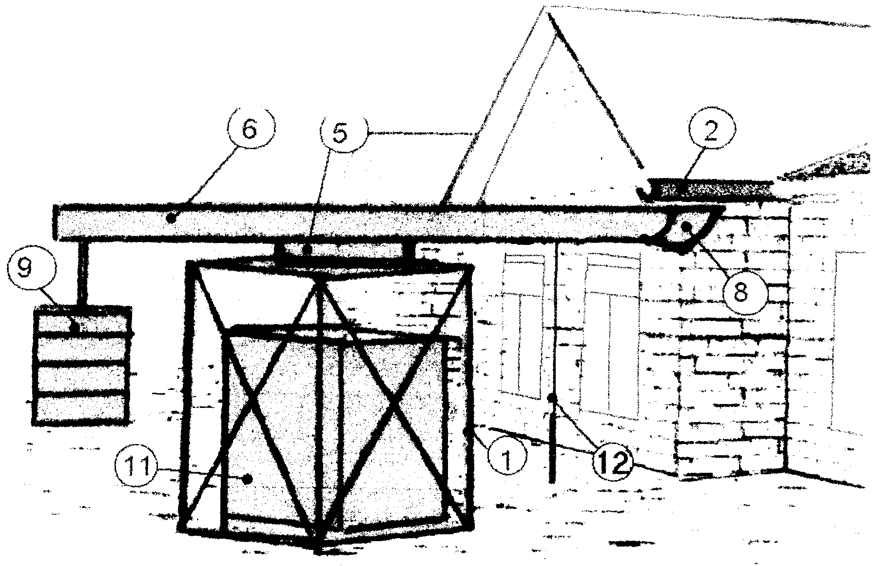
Полезная модель относится к строительству, в частности к конструкциям водоотводов для крыш зданий, а более конкретно, может найти применение в качестве устройства для сбора дождевой воды. Каркасное устройство для сбора дождевой воды состоит из остова, вращающейся площадки, швеллерной стрелы, желоба сбора воды, водоприемника, противовеса и телескопической рукояти. Остов собирается в форме прямоугольной призмы 1, нижняя сторона которой устанавливается на земле, а верхняя сторона достигает уровня расположения желоба 2 системы водоотвода с крыши, при этом в точке пересечения осей симметрии верхней стороны конструктивно фиксируется муфта 3, вмещающая в себя вал 4 вращающейся площадки 5, к которой крепится швеллерная стрела 6 «альтернативного» желоба 7 сбора воды. С одного торца стрела оканчивается водоприемником 8, а с другого - противовесом 9. Внутри швеллерной стрелы 6 устанавливается «альтернативный» желоб 7 сбора воды, соединенный с одной стороны с водоприемником 8, а с другой стороны имеющий открытый торец 10, расположенный в границах периметра верхней стороны остова 1. Внутри каркасного остова 1 помещается резервуар 11 для сбора и хранения дождевой воды, с любыми габаритами, ограниченными объемом призмы, а водоприемник 8 швеллерной стрелы 6 имеет возможность, путем вращения площадки 5, подводиться под открытый торец желоба 2 системы водоотвода с крыши. При этом образуется новый путь прохождения дождевой воды: через водоприемник 8 и «альтернативный» желоб 7 сбора воды - в резервуар 11 для сбора и хранения. Вращение площадки 5, жестко связанной со швеллерной стрелой 6, производится путем манипулирования телескопической рукоятью 12, присоединенной к The invention relates to the construction, in particular, to the design of drainage systems for roofs of buildings, and more specifically, may find application as a device for collecting rainwater. The frame device for collecting rainwater consists of a core, a rotating platform, a channel boom, a gutter for collecting water, a water intake, a counterweight and a telescopic handle. The skeleton is assembled in the form of a rectangular prism 1, the lower side of which is mounted on the ground, and the upper side reaches the level of the gutter 2 of the roof drainage system, while at the point of intersection of the symmetry axes of the upper side the coupling 3 is structurally fixed, accommodating the shaft 4 of the rotating platform 5 , to which the channel boom 6 of the “alternative” trough 7 of the water collection is attached. At one end, the arrow ends with water inlet 8, and on the other with a counterbalance 9. Inside the channel boom 6, an “alternative” water collection chute 7 is installed, connected to the water inlet 8 on one side and having an open end 10 located on the perimeter of the upper sides of the skeleton 1. Inside the frame skeleton 1 is placed a reservoir 11 for collecting and storing rainwater, with any dimensions limited by the volume of the prism, and the water intake 8 of the channel boom 6 has the opportunity, by rotating the platform 5, to feed One open end of the gutter 2 roof drainage systems. In this case, a new path of rainwater passage is formed: through the water intake 8 and the "alternative" trough 7 for collecting water - into the tank 11 for collection and storage. The rotation of the platform 5, rigidly connected with the channel boom 6, is carried out by manipulating the telescopic handle 12 attached to
одной из внешних сторон стрелы между границами периметра призмы 1 и водоприемником 8. Предложенная конструкция позволяет применять для сбора дождевой воды резервуары различных габаритов, дистанционно манипулировать подвижными частями устройства для достижения необходимого расположения составляющих его узлов, проводить технологические мероприятия без привлечения специалистов.one of the external sides of the boom between the boundaries of the perimeter of prism 1 and the water inlet 8. The proposed design allows the use of tanks of various sizes to collect rainwater, remotely manipulate the moving parts of the device to achieve the necessary arrangement of its components, and carry out technological measures without the involvement of specialists.
Description
Изобретение относится к строительству, в частности к устройствам для отвода и сбора воды с крыш.The invention relates to the construction, in particular, to devices for draining and collecting water from roofs.
Известно приспособление для сбора дождевой воды по Европейскому патенту 1350902, МПК 7 E 04 D 13/08; Е 03 В 3/02, 08.10.2003 г. Приспособление выполнено в виде врезки в водосточную трубу между ее концами и содержит переключающее устройство клапанного типа, которое может быть установлено в двух различных положениях: для проведения воды «альтернативным» путем к резервуару для сборки или вниз от врезки по трубе к земле - «традиционным» путем.A device for collecting rainwater according to European patent 1350902, IPC 7 E 04 D 13/08; E 03 B 3/02, 10/08/2003. The device is made as a cut-in into a drain pipe between its ends and contains a valve-type switching device that can be installed in two different positions: for conducting water in an "alternative" way to the assembly tank or down from the tie-in through the pipe to the ground - the "traditional" way.
Недостатком этой конструкции является отсутствие возможности мобильной замены габаритов и локализации на местности резервуаров для сбора и аккумуляции дождевой воды.The disadvantage of this design is the lack of the possibility of mobile replacement of the dimensions and localization on the ground of reservoirs for collecting and accumulating rainwater.
Технической задачей, на решение которой направлена заявляемая конструкция, является быстрое и легкое изменение направления потока воды с «традиционного» на «альтернативное» с тем, чтобы иметь возможность произвести сбор и аккумуляцию воды в наземных резервуарах, которые при этом могут иметь вариации в габаритах и локализации на местности.The technical problem to which the claimed design is directed is to quickly and easily change the direction of the water flow from “traditional” to “alternative” in order to be able to collect and accumulate water in land tanks, which may have variations in size and localization on the ground.
Поставленная задача решается тем, что собирается легкая каркасная металлоконструкция - остов (Фиг.1) в форме прямоугольной призмы 1, нижняя сторона которой устанавливается на земле, а верхняя сторона достигает уровня расположения желоба 2 системы водоотвода с крыши, при этом в точке пересечения осей симметрии верхней стороны конструктивно фиксируется муфта 3, вмещающая в себя вал 4 The problem is solved in that a light frame metal structure is assembled - the skeleton (Fig. 1) in the form of a rectangular prism 1, the lower side of which is mounted on the ground, and the upper side reaches the level of the gutter 2 of the roof drainage system, while at the intersection of the axes of symmetry the upper side is structurally fixed coupling 3, accommodating the shaft 4
вращающейся площадки 5, к которой крепится швеллерная стрела 6 «альтернативного» желоба 7 сбора воды (Фиг.2).rotating platform 5, to which the channel boom 6 of the "alternative" gutter 7 for collecting water is attached (Figure 2).
Швеллерная стрела 6 «альтернативного» желоба 7 сбора воды представляет собой имеющую профиль швеллера (с вертикально-расположенными полками) сборную металлоконструкцию из перфорированных полос, торцы которой расположены асимметрично относительно вращаемой площадки 5. С одного торца стрела оканчивается водоприемником 8, а с другого - противовесом 9.The channel boom 6 of the "alternative" gutter 7 for collecting water is a prefabricated metal structure with perforated strips having a channel profile (with vertically arranged shelves), the ends of which are located asymmetrically relative to the rotatable platform 5. At one end, the arrow ends with a water intake 8, and on the other, with a counterweight 9.
Внутри швеллерной стрелы 6 устанавливается «альтернативный» желоб 7 сбора воды, соединенный с одной стороны с водоприемником 8, а с другой стороны имеющий открытый торец 10, расположенный в границах периметра верхней стороны остова 1.Inside the channel boom 6, an “alternative” water collection chute 7 is installed, connected on the one hand to the water intake 8, and on the other hand having an open end 10 located within the perimeter of the upper side of the core 1.
Внутри каркасного остова 1 помещается резервуар 11 для сбора и хранения дождевой воды, с любыми габаритами, ограниченными объемом призмы, а водоприемник 8 швеллерной стрелы 6 имеет возможность, путем вращения площадки 5, подводиться под открытый торец желоба 2 системы водоотвода с крыши, образованный, например, с помощью специального устройства для размыкания водосточного желоба (Патент РФ 47408, МПК 7 Е 04 D 13/076, 27.08.2005 г.). При этом образуется новый путь прохождения дождевой воды: через водоприемник 8 и «альтернативный» желоб 7 сбора воды - в резервуар 11 для сбора и хранения. Вращение площадки 5, жестко связанной со швеллерной стрелой 6, производится путем манипулирования телескопической рукоятью 12, присоединенной к одной из внешних сторон стрелы между границами периметра призмы 1 и водоприемником 8.Inside the frame skeleton 1 is placed a reservoir 11 for collecting and storing rainwater, with any dimensions limited by the volume of the prism, and the water intake 8 of the channel boom 6 is able, by rotating the platform 5, to be brought under the open end of the gutter 2 of the roof drainage system, formed, for example using a special device for opening the gutter (RF Patent 47408, IPC 7 E 04 D 13/076, 08/27/2005). In this case, a new path of rainwater passage is formed: through the water intake 8 and the "alternative" trough 7 for collecting water - into the tank 11 for collection and storage. The rotation of the platform 5, rigidly connected with the channel boom 6, is done by manipulating the telescopic handle 12 attached to one of the outer sides of the boom between the borders of the perimeter of the prism 1 and the water inlet 8.
Техническими преимуществами предлагаемого устройства являются следующие возможности:The technical advantages of the proposed device are the following features:
- применение для сбора дождевой воды резервуаров различных габаритов без изменения конструкции устройства;- use for collecting rainwater tanks of various sizes without changing the design of the device;
- быстрая и легкая сборка конструкции в выбранном месте локализации;- quick and easy assembly of the structure in the selected location;
- дистанционное манипулирование подвижными частями устройства для достижения необходимого расположения составляющих его узлов;- remote manipulation of the moving parts of the device to achieve the necessary location of its components;
- возможность проведения технологических мероприятий без привлечения специалистов;- the ability to carry out technological activities without the involvement of specialists;
- снижение стоимости эксплуатации водоотвода.- reduction in the cost of operating the drainage system.
Claims (7)
Priority Applications (1)
| Application Number | Priority Date | Filing Date | Title |
|---|---|---|---|
| RU2005139995/22U RU53318U1 (en) | 2005-12-20 | 2005-12-20 | FRAMES FOR RAIN WATER COLLECTION |
Applications Claiming Priority (1)
| Application Number | Priority Date | Filing Date | Title |
|---|---|---|---|
| RU2005139995/22U RU53318U1 (en) | 2005-12-20 | 2005-12-20 | FRAMES FOR RAIN WATER COLLECTION |
Publications (1)
| Publication Number | Publication Date |
|---|---|
| RU53318U1 true RU53318U1 (en) | 2006-05-10 |
Family
ID=36657606
Family Applications (1)
| Application Number | Title | Priority Date | Filing Date |
|---|---|---|---|
| RU2005139995/22U RU53318U1 (en) | 2005-12-20 | 2005-12-20 | FRAMES FOR RAIN WATER COLLECTION |
Country Status (1)
| Country | Link |
|---|---|
| RU (1) | RU53318U1 (en) |
Cited By (23)
| Publication number | Priority date | Publication date | Assignee | Title |
|---|---|---|---|---|
| USD683229S1 (en) | 2012-06-07 | 2013-05-28 | Colgate-Palmolive Company | Container |
| USD683230S1 (en) | 2012-06-07 | 2013-05-28 | Colgate-Palmolive Company | Container |
| USD683237S1 (en) | 2012-06-07 | 2013-05-28 | Colgate-Palmolive Company | Container |
| USD683631S1 (en) | 2012-06-07 | 2013-06-04 | Colgate-Palmolive Company | Container |
| USD684064S1 (en) | 2012-06-07 | 2013-06-11 | Colgate-Palmolive Company | Container |
| USD684473S1 (en) | 2012-06-07 | 2013-06-18 | Colgate-Palmolive Company | Container |
| USD684864S1 (en) | 2012-06-07 | 2013-06-25 | Colgate-Palmolive Company | Container |
| USD688131S1 (en) | 2012-06-07 | 2013-08-20 | Colgate-Palmolive Company | Container |
| USD688130S1 (en) | 2012-06-07 | 2013-08-20 | Colgate-Palmolive Company | Container |
| USD688558S1 (en) | 2012-06-07 | 2013-08-27 | Colgate-Palmolive Company | Container |
| USD689367S1 (en) | 2012-06-07 | 2013-09-10 | Colgate-Palmolive Company | Container |
| USD689775S1 (en) | 2012-06-07 | 2013-09-17 | Colgate-Palmolive Company | Container |
| USD690204S1 (en) | 2012-06-07 | 2013-09-24 | Colgate-Palmolive Company | Container |
| USD691042S1 (en) | 2012-06-07 | 2013-10-08 | Colgate-Palmolive Company | Container closure |
| USD691044S1 (en) | 2012-06-07 | 2013-10-08 | Colgate-Palmolive Company | Container closure |
| USD691045S1 (en) | 2012-06-07 | 2013-10-08 | Colgate-Palmolive Company | Container closure |
| USD691043S1 (en) | 2012-06-07 | 2013-10-08 | Colgate-Palmolive Company | Container closure |
| USD694629S1 (en) | 2012-06-07 | 2013-12-03 | Colgate-Palmolive Company | Container |
| USD694630S1 (en) | 2012-06-07 | 2013-12-03 | Colgate-Palmolive Company | Container |
| USD694631S1 (en) | 2012-06-07 | 2013-12-03 | Colgate-Palmolive Company | Container |
| USD708949S1 (en) | 2012-06-07 | 2014-07-15 | Colgate-Palmolive Company | Cap for a container |
| USD708948S1 (en) | 2012-06-07 | 2014-07-15 | Colgate-Palmolive Company | Cap for a container |
| RU199507U1 (en) * | 2020-01-09 | 2020-09-04 | Валерий Павлович Левицкий | Device for collecting and storing rainwater with a volume of more than 3000 m3 |
-
2005
- 2005-12-20 RU RU2005139995/22U patent/RU53318U1/en not_active IP Right Cessation
Cited By (25)
| Publication number | Priority date | Publication date | Assignee | Title |
|---|---|---|---|---|
| USD683229S1 (en) | 2012-06-07 | 2013-05-28 | Colgate-Palmolive Company | Container |
| USD683230S1 (en) | 2012-06-07 | 2013-05-28 | Colgate-Palmolive Company | Container |
| USD683237S1 (en) | 2012-06-07 | 2013-05-28 | Colgate-Palmolive Company | Container |
| USD683631S1 (en) | 2012-06-07 | 2013-06-04 | Colgate-Palmolive Company | Container |
| USD684064S1 (en) | 2012-06-07 | 2013-06-11 | Colgate-Palmolive Company | Container |
| USD684473S1 (en) | 2012-06-07 | 2013-06-18 | Colgate-Palmolive Company | Container |
| USD684864S1 (en) | 2012-06-07 | 2013-06-25 | Colgate-Palmolive Company | Container |
| USD688131S1 (en) | 2012-06-07 | 2013-08-20 | Colgate-Palmolive Company | Container |
| USD688130S1 (en) | 2012-06-07 | 2013-08-20 | Colgate-Palmolive Company | Container |
| USD688558S1 (en) | 2012-06-07 | 2013-08-27 | Colgate-Palmolive Company | Container |
| USD689367S1 (en) | 2012-06-07 | 2013-09-10 | Colgate-Palmolive Company | Container |
| USD689775S1 (en) | 2012-06-07 | 2013-09-17 | Colgate-Palmolive Company | Container |
| USD690204S1 (en) | 2012-06-07 | 2013-09-24 | Colgate-Palmolive Company | Container |
| USD691042S1 (en) | 2012-06-07 | 2013-10-08 | Colgate-Palmolive Company | Container closure |
| USD691044S1 (en) | 2012-06-07 | 2013-10-08 | Colgate-Palmolive Company | Container closure |
| USD691045S1 (en) | 2012-06-07 | 2013-10-08 | Colgate-Palmolive Company | Container closure |
| USD691043S1 (en) | 2012-06-07 | 2013-10-08 | Colgate-Palmolive Company | Container closure |
| USD694629S1 (en) | 2012-06-07 | 2013-12-03 | Colgate-Palmolive Company | Container |
| USD694624S1 (en) | 2012-06-07 | 2013-12-03 | Colgate-Palmolive Company | Container closure |
| USD694630S1 (en) | 2012-06-07 | 2013-12-03 | Colgate-Palmolive Company | Container |
| USD694631S1 (en) | 2012-06-07 | 2013-12-03 | Colgate-Palmolive Company | Container |
| USD700056S1 (en) | 2012-06-07 | 2014-02-25 | Colgate-Palmolive Company | Container |
| USD708949S1 (en) | 2012-06-07 | 2014-07-15 | Colgate-Palmolive Company | Cap for a container |
| USD708948S1 (en) | 2012-06-07 | 2014-07-15 | Colgate-Palmolive Company | Cap for a container |
| RU199507U1 (en) * | 2020-01-09 | 2020-09-04 | Валерий Павлович Левицкий | Device for collecting and storing rainwater with a volume of more than 3000 m3 |
Similar Documents
| Publication | Publication Date | Title |
|---|---|---|
| RU53318U1 (en) | FRAMES FOR RAIN WATER COLLECTION | |
| JP6826256B2 (en) | Rainwater guidance collection device on the ceiling of the building | |
| KR101340799B1 (en) | Rainwater collecting device and facility for using rainwater with the device | |
| KR101574644B1 (en) | A Rainwater Gathering Equipment | |
| CN109372088A (en) | A kind of self-closed inlet for stom water of easy cleaning | |
| US20150008229A1 (en) | Rain Water Divert and Collection Device | |
| CN114250841B (en) | Rainwater comprehensive treatment device for four courtyards in old urban area | |
| CN209457129U (en) | A kind of self-closed inlet for stom water of easy cleaning | |
| CN109779006B (en) | Effectively solve vestibule of ponding problem | |
| KR101932145B1 (en) | An Initial rainwater exclusion device using the flowmeter measuring precipitation per unit area | |
| GB2228521A (en) | Roof tile rain collector | |
| JP3129492U (en) | Rainwater dust removal system | |
| JP2011137299A (en) | Rainwater intake device | |
| JPH0885982A (en) | Rainwater intake device | |
| CN206308915U (en) | A kind of roof greening rainwater collection irrigation device based on sponge the idea of the city | |
| CN206564951U (en) | A kind of drainage system of strawberry greenhouse | |
| JPH10168952A (en) | Water storage system of rain water | |
| CN113187078A (en) | Rainwater treatment device | |
| JP2003155761A (en) | Rainwater storing apparatus | |
| CN208918145U (en) | Plant pitched roof | |
| JP2009121217A (en) | Initial rainwater removing device and rainwater storage system using the same | |
| CN208309756U (en) | A kind of ecology of scenic area water circulation system | |
| CN209927544U (en) | Rainproof system of air comprehensive sampler | |
| CN217923864U (en) | Rainwater collecting device | |
| JP4846528B2 (en) | Water storage tank with water use adjustment function |
Legal Events
| Date | Code | Title | Description |
|---|---|---|---|
| MM1K | Utility model has become invalid (non-payment of fees) |
Effective date: 20061221 |