RU2822103C1 - Road-railway crossing through kerch strait - Google Patents
Road-railway crossing through kerch strait Download PDFInfo
- Publication number
- RU2822103C1 RU2822103C1 RU2023119441A RU2023119441A RU2822103C1 RU 2822103 C1 RU2822103 C1 RU 2822103C1 RU 2023119441 A RU2023119441 A RU 2023119441A RU 2023119441 A RU2023119441 A RU 2023119441A RU 2822103 C1 RU2822103 C1 RU 2822103C1
- Authority
- RU
- Russia
- Prior art keywords
- stayed
- cable
- overpasses
- barge
- strait
- Prior art date
Links
- 230000008878 coupling Effects 0.000 claims description 13
- 238000010168 coupling process Methods 0.000 claims description 13
- 238000005859 coupling reaction Methods 0.000 claims description 13
- XLYOFNOQVPJJNP-UHFFFAOYSA-N water Substances O XLYOFNOQVPJJNP-UHFFFAOYSA-N 0.000 abstract description 10
- 238000010276 construction Methods 0.000 abstract description 3
- 230000001133 acceleration Effects 0.000 abstract 1
- 239000000126 substance Substances 0.000 abstract 1
- 239000012634 fragment Substances 0.000 description 7
- 238000003032 molecular docking Methods 0.000 description 6
- 238000000034 method Methods 0.000 description 5
- 230000001681 protective effect Effects 0.000 description 3
- 230000015572 biosynthetic process Effects 0.000 description 2
- 239000003351 stiffener Substances 0.000 description 2
- 230000007704 transition Effects 0.000 description 2
- 230000000903 blocking effect Effects 0.000 description 1
- 239000002184 metal Substances 0.000 description 1
- 239000011150 reinforced concrete Substances 0.000 description 1
- 230000001360 synchronised effect Effects 0.000 description 1
Images

Abstract
Description
Изобретение относится к области строительства, а именно, к строительству транспортных переходов через водные препятствия.The invention relates to the field of construction, namely, to the construction of transport crossings over water obstacles.
Известен проект транспортного перехода (патент РФ 270.93.77 от 17.02.2019 г.) в котором путепроводы стоят на многочисленных опорах.There is a well-known project for a transport crossing (RF patent 270.93.77 dated February 17, 2019) in which the overpasses stand on numerous supports.
Недостатком известного проекта является проблема пропуска ледохода из-за наличия большого числа опор.The disadvantage of the known project is the problem of missing ice drift due to the presence of a large number of supports.
Задачей изобретения является разработка конструкции транспортного перехода, обеспечивающего пропуск автомобильно-железнодорожных потоков, судов, а также ледохода.The objective of the invention is to develop a design for a transport crossing that ensures the passage of road and rail traffic, ships, and ice drift.
Поставленная задача решается тем, что два вантовых путепровода транспортного перехода оборудованы выдвижными опорами, которые 360 дней в году стоят вставленными в персональные соединительные муфты, закрепленные на глубине 2,5 м на сваях, забитых в дно пролива и обеспечивают штатный пропуск автомобильно-железнодорожных потоков, а на время ледохода (6 дней), поднимаются на вантовые путепроводы и, тем самым, освобождают проходы под Байтовыми путепроводами для пропуска ледохода, по окончанию которого выдвижные опоры снова опускаются с вантовых путепроводов и вставляются в свои персональные соединительные муфты, закрепленные на сваях забитых в дно пролива, и обеспечивают штатный пропуск автомобильно-железнодорожных потоков по вантовым путепроводам.The task is solved by the fact that two cable-stayed overpasses of the transport crossing are equipped with retractable supports, which 360 days a year stand inserted into personal connecting couplings, fixed at a depth of 2.5 m on piles driven into the bottom of the strait and ensure the regular passage of road and railway flows, and during the ice drift (6 days), they climb onto the cable-stayed overpasses and, thereby, free up the passages under the Byte overpasses for the passage of the ice drift, at the end of which the retractable supports are again lowered from the cable-stayed overpasses and inserted into their personal connecting couplings, fixed on piles driven into the bottom of the strait, and ensure the regular passage of road and railway flows along cable-stayed overpasses.
Заявленное изобретение поясняется чертежами, гдеThe claimed invention is illustrated by drawings, where
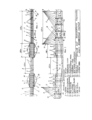
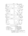
на Фиг. 1 - дан общий вид транспортного перехода, вид сверху, баржевый мост соединен;in Fig. 1 - a general view of the transport crossing is given, a top view, the barge bridge is connected;
на Фиг. 2 - общий вид транспортного перехода, баржевый мост соединен, вид сбоку;in Fig. 2 - general view of the transport crossing, the barge bridge is connected, side view;
на Фиг. 3 - общий вид транспортного перехода с разведенным баржевым мостом, вид сбоку;in Fig. 3 - general view of a transport crossing with an extended barge bridge, side view;
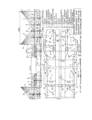
на Фиг. 4 - фрагмент транспортного перехода, вид сверху;in Fig. 4 - fragment of a transport crossing, top view;
на Фиг. 5 - выдвижная опора опущенная;in Fig. 5 - retractable support lowered;
на Фиг. 6 - выдвижная опора поднята;in Fig. 6 - retractable support is raised;
на Фиг. 7 - фрагмент поперечного разреза вантового путепровода, выдвижные опоры опущены;in Fig. 7 - fragment of a cross-section of a cable-stayed overpass, retractable supports are lowered;
на Фиг. 8 - фрагмент вантового путепровода, выдвижная опора опущена, вид сбоку;in Fig. 8 - fragment of a cable-stayed overpass, the retractable support is lowered, side view;
на Фиг. 9 - фрагмент вантового путепровода, выдвижная опора поднята, вид сбоку;in Fig. 9 - fragment of a cable-stayed overpass, the retractable support is raised, side view;
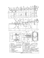
на Фиг. 10 - фрагмент вантового путепровода, выдвижные опоры подняты, поперечный разрез;in Fig. 10 - fragment of a cable-stayed overpass, retractable supports raised, cross section;
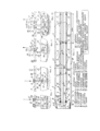
на Фиг. 11 - фрагмент транспортного перехода, вид сверху;in Fig. 11 - fragment of a transport crossing, top view;
на Фиг. 12 - поперечный разрез вантового путепровода, выдвижные опоры опущены;in Fig. 12 - cross-section of a cable-stayed overpass, retractable supports lowered;
на Фиг. 13 - фрагмент вантового путепровода, расположение ребер жесткости, вид сверху;in Fig. 13 - fragment of a cable-stayed overpass, location of stiffeners, top view;
на Фиг. 14 - самоходная баржа №1, вид сбоку;in Fig. 14 - self-propelled barge No. 1, side view;
на Фиг. 15 - самоходная баржа №1, вид сверху;in Fig. 15 - self-propelled barge No. 1, top view;
на Фиг. 16 - самоходная баржа №2, вид сбоку;in Fig. 16 - self-propelled barge No. 2, side view;
на Фиг. 17 - самоходная баржа №2, вид сверху;in Fig. 17 - self-propelled barge No. 2, top view;
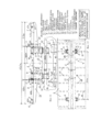
на Фиг. 18 - общий вид 3-х секций платформы 3 и самоходной баржи №1, вид сбоку;in Fig. 18 - general view of 3 sections of
на Фиг. 19 - общий вид перехода с самоходной баржи №1 на три секции платформы 3, вид сбоку;in Fig. 19 - general view of the transition from self-propelled barge No. 1 to three sections of
на Фиг. 20 - показан узел фиксации секции 3 платформы в наклонном положении, вид сверху;in Fig. 20 - shows the fixation unit for
на Фиг. 21 - показан узел фиксации секции 3 платформы в наклонном положении, вид сбоку;in Fig. 21 - shows the fixation unit for
на Фиг. 22 - показана панель узла фиксации с отверстиями для засова 17 с электроприводом.in Fig. 22 - shows a panel of the fixation unit with holes for a
Автомобильно-железнодорожный переход через Керченский пролив состоит из раздвижного баржевого моста, образованного состыкованными самоходными баржами ледокольного класса, которые при расстыковке заплывают в свои защитные доки, образованные защитными стенами - 2 и накрытые платформами - 3, со стоящими из секций, которые своими краями надеты на направляющие сваи - 4, забитыми в дно пролива - 5, и, которые с помощью электролебедок - 6, закрепленных на верхних концах направляющих свай - 4, поднимаются (опускаются) диспетчером в зависимости от уровня воды в проливе, а также при обеспечении плавного подъема (спуска) с примыкающих секций платформы 3 на баржевый мост - 1. На продольной оси самоходных барж - 1, секций - 3 платформ и вантовых путепроводов - 7 уложен ж/д путь - 8, по обе стороны которого оборудованы две автополосы - 9. Байтовый путепровод - 7 держится с помощью пилонов - 10, попарно вбитых в дно пролива - 5 через каждые 150 м. и системами вант - 11. На раме путепровода - 7 через каждые 30 м. закреплена пара направляющих втулок - 12, в которые вставлены цилиндрические выдвижные опоры - 13, которые с помощью электродвигателей - 14, зубчатых шестеренок - 15 и зубчатых пластин - 16, закрепленных вдоль каждой выдвижной опоры - 13 с двух сторон, перемещаются в направляющих втулках - 12 вверх перед ледоходом и фиксируются в поднятом положении двумя засовами - 17, снабженных электроприводами - 18, через отверстия - 19 в выдвижных опорах - 13. После ледохода каждая выдвижная опора - 13 опускается по направляющей втулке - 12 с помощью электродвигателей - 14 и зубчатых шестеренок - 15 и зубчатых пластин - 16 вниз и вставляются в персональную соединительную муфту - 20 в верхнее углубление - 21, где своей пяткой - 22 упирается в пружину - 23, закрепленную на металлической пластине - 24, забетонированной в соединительной муфте - 20, которая надета своим нижним углублением - 25 на две забивные сваи - 26, продетые через отверстия в ж/б плите - 27 и забитые в дно пролива - 5.The road-railway crossing across the Kerch Strait consists of a sliding barge bridge formed by docked icebreaker-class self-propelled barges, which, when undocking, float into their protective docks, formed by protective walls - 2 and covered with platforms - 3, with sections standing on them, their edges are put on guide piles - 4, driven into the bottom of the strait - 5, and which, with the help of electric winches - 6, attached to the upper ends of the guide piles - 4, are raised (lowered) by the dispatcher depending on the water level in the strait, as well as while ensuring a smooth rise ( descent) from adjacent sections of
Конструкция вантового путепровода - 7 усилена поперечными ребрами жесткости - 28. Вдоль продольных краев самоходных барж - 1, секций платформ 3 и вантовых путепроводов - 7 оборудована пешеходная дорожка - 29. Вдоль железнодорожной зоны - 8, автомобильных полос - 9 и пешеходных дорожек - 29 уложены бордюры - 30 и отбойники -31.The structure of the cable-stayed overpass - 7 is reinforced with transverse stiffeners - 28. A pedestrian path - 29 is installed along the longitudinal edges of self-propelled barges - 1, sections of
В районе пилонов - 10 у автополос - 9 имеются аварийные автомобильные карманы - 32. Оба защитных дока - 2 с двух сторон имеют противоледоходную защиту - 33, а пилоны - 10 с двух сторон защищены от ледохода ледорезами - 34, забитыми в дно пролива - 5 в одном створе с пилонами - 10, в 50 метрах от них и высотою до 3-х метров над уровнем воды - 35 в заливе. Самоходные баржи - 1 снабжены двигателями - 36, гребными винтами - 37, кабиной машиниста - 38 и рулями - 39, а в носовой части верхним выступом - 40, средним выступом - 41, нижним выступом - 42, верхней выемкой - 43, средней выемкой - 44, нижней выемкой - 45. На кормовой части каждой самоходной баржи - 1 выполнена приемная площадка - 46 шириной 22 метра, у которой уровень пола ниже уровня палубы самоходной баржи - 1 на 15 см. На площадке - 46 отсутствуют ж/д пути и автополосы с бордюрами и предназначена она для приема крайней секции - 3 платформы, которая при опускании устанавливается на площадке - 46 и формирует общий для 2-х крайних секций 3 платформы спуск 47 с платформы - 3 на самоходную баржу - 1, так как на 1-й крайней секции - 3 платформы ж/д путь и две автополосы выполнены с уклоном - 48. Для обеспечения плавного перехода на самоходную баржу - 1 с крайней секции 3 платформы, крайняя секция 3 снабжена одним шарнирно-закрепленным ж/д трапом - 49 и двумя автомобильными трапами - 50. Ж/д путь - 8 на ж/д трапе - 49 соединяется с ж/д путем - 8 на самоходной барже №1 с помощью рельсовых вставок - 51 и рельсовых накладок. Вантовый путепровод - 7 собран на продольной раме - 52.In the area of the pylons - 10, the highway lanes - 9 have emergency car pockets - 32. Both protective docks - 2 have anti-ice protection on both sides - 33, and the pylons - 10 on both sides are protected from ice drift by ice cutters - 34, driven into the bottom of the strait - 5 in the same alignment with the pylons - 10, 50 meters from them and up to 3 meters above the water level - 35 in the bay. Self-propelled barges - 1 are equipped with engines - 36, propellers - 37, driver's cabin - 38 and rudders - 39, and in the bow with an upper protrusion - 40, a middle protrusion - 41, a lower protrusion - 42, an upper recess - 43, a middle recess - 44, with a lower recess - 45. On the aft part of each self-propelled barge - 1 there is a receiving platform - 46 with a width of 22 meters, whose floor level is below the level of the deck of the self-propelled barge - 1 by 15 cm. On the platform - 46 there are no railway tracks and highway lanes with curbs and is designed to receive the outermost section - 3 platform, which, when lowered, is installed on the platform - 46 and forms a
Для фиксации секций 3 платформы в установленных диспетчером положениях используются узлы фиксации, состоящие из закрепленных на секциях 3 засовов - 17 с электроприводами, которые взаимодействуют с отверстиями панели фиксации - 52, закрепленной на направляющих сваях - 4.To fix
Все засовы с электроприводами снабжены конечными датчиками, показания которых выведены на диспетчерский пульт управления. К углам стыковки на самоходных баржах, к затворам эл. приводами на секциях платформ и на выдвижных опорах вантовых путепроводов подведены сети пневмо-термических систем.All bolts with electric drives are equipped with end sensors, the readings of which are displayed on the dispatch control panel. To the docking corners on self-propelled barges, to the electric gates. drives on sections of platforms and on retractable supports of cable-stayed overpasses provide networks of pneumatic-thermal systems.
Работа раздвижного баржевого мостаOperation of a sliding barge bridge
За исходное положение принимается ситуация, когда моет разведен и самоходные баржи находятся в своих доках. Диспетчера 2-х платформ 3, после согласования вопроса о стыковке самоходных барж, дают команду машинистам самоходных барж и те включают двигатели - 36 и самоходные баржи выплывают из своих доков навстречу друг другу и через 100 метров стыкуются на середине судоходного прохода раздвижного баржевого моста. Операции стыковки приведены в патенте РФ 270.9377 от 17.12.2019 г. После получения докладов о стыковке самоходных барж, каждый диспетчер с пульта управления включает электролебедки на направляющих сваях - 4 крайней секции платформы и горизонтально опускает ее на 1 метр.The initial position is taken to be the situation when the wash is open and the self-propelled barges are in their docks. The dispatchers of 2
После этого, диспетчер опять включает электролебедки на первых двух крайних направляющих сваях - 4 первой секции и опускает край первой секции платформы с трапами - 49 и 50 на площадку - 46 самоходной баржи. Включив электролебедки на первых двух направляющих сваях - 4 второй секции платформы, диспетчер опускает передний край 2-й платформы до ее стыковки с краем 1-й наклоненной секцией платформы. В результате этих операций формируется общий спуск - 47 из 2-х наклоненных крайних секций 1 и 2, который обеспечивает спуск с 3-й секции платформы на самоходную баржу (Фиг. 19). Наклоненные секции 1 и 2 фиксируются диспетчером в установленном положении с помощью узлов фиксации - засовами с электроприводами и отверстиями панели фиксации, После этого, диспетчер дает команду путевым работникам на соединение ж/д рельсовых стыков на самоходной барже и на ж/д трапе - 49 с помощью рельсовых вставок - 51 и рельсовых накладок (Фиг. 19). По окончанию путевых работ и докладов путейцев, диспетчера согласовывают начало движения по баржевому мосту и включают разрешающие сигналы на светофорах для автотранспорта и согласовывают порядок движения ж/д состава через баржевый мост.After this, the dispatcher again turns on the electric winches on the first two outer guide piles - 4 of the first section and lowers the edge of the first section of the platform with ladders - 49 and 50 onto the platform - 46 of the self-propelled barge. Having turned on the electric winches on the first two guide piles - 4 of the second section of the platform, the dispatcher lowers the front edge of the 2nd platform until it docks with the edge of the 1st inclined section of the platform. As a result of these operations, a common descent is formed - 47 from 2 inclined
Разведение баржевого мостаRaising the barge bridge
После согласования вопроса о разведении баржевого моста, диспетчера светофорами перекрывают движение ж/д и автотранспорта через баржевый мост. После освобождения баржевого моста от транспорта, диспетчер дает команду путевым рабочим снять рельсовые накладки на ж/д стыках на барже и на ж/д трапе крайней секции платформы. Получив доклад о выполнении путевых работ, диспетчер включает на пульте управления четыре электропривода 4-х засовов узла блокировки и разблокирует первую крайнюю секцию платформы. После этого включает 2 электролебедки на 2-х первых направляющих сваях крайней секции 1 платформы и переводит секцию 1 платформы из наклонного положения в горизонтальное положение. Включает 4 электролебедки на 4-х направляющих сваях крайней секции 1 платформы и поднимает ее на 1,5 метра над площадкой 46 самоходной баржи. После этого включает 4 электропривода, 4-х засовов на 4-х направляющих сваях 2-й платформы и разблокирует 2-ю секцию платформы. После этого диспетчер включает 2 электролебедки и на 2-х первых направляющих сваях 2-й секции платформы и переводит наклонную 2-ю секцию платформы в горизонтальное положение на высоте 1,5 метра над площадкой 46 самоходной баржи. Диспетчер блокирует 1-ю и 2-ю секции платформы в горизонтальном положении на высоте 1,5 метра над площадкой 46 самоходной баржи с помощью узлов фиксации. После этого диспетчера дают команду работникам, находящимся на узле стыковки самоходных барж, выполнить операцию по расстыковке самоходных барж. После получения докладов о выполнении расцепки самоходных барж, диспетчера дают команды машинистам на включение двигателей 36 и заплывание самоходных барж в свои доки. Самоходные баржи заплывают в свои доки и освобождают судоходный проход раздвижного баржевого моста для прохода судов.After agreeing on the issue of raising the barge bridge, the dispatcher uses traffic lights to block the movement of railways and vehicles across the barge bridge. After the barge bridge is cleared of traffic, the dispatcher gives the command to the track workers to remove the rail linings at the railway joints on the barge and on the railway ladder of the outer section of the platform. Having received a report on the completion of track work, the dispatcher turns on the four electric drives of the 4 bolts of the blocking unit on the control panel and unlocks the first outer section of the platform. After this, it turns on 2 electric winches on the first 2 guide piles of the outermost section of
Работа раздвижного баржевого моста при изменении уровня воды в проливеOperation of a sliding barge bridge when the water level in the strait changes
При изменении уровня воды в проливе на 0,5 м. датчики в ДОКах проинформируют диспетчеров об этом.If the water level in the strait changes by 0.5 m, sensors in the docks will inform dispatchers about this.
Диспетчера согласованно останавливают светофорами авто и ж/д движение через баржевый мост. После освобождения баржевого моста от транспорта диспетчера дают указания путевым работникам и те снимают рельсовые накладки со стыков ж/д путей между баржей и ж/д трапами.The dispatcher coordinates traffic lights to stop automobile and railway traffic across the barge bridge. After the barge bridge is freed from transport, the dispatcher gives instructions to the track workers and they remove the rail pads from the joints of the railway tracks between the barge and the railway gangways.
После выполнения путевых работ и доклада путейцев, каждый диспетчер через углы фиксации разблокирует фиксацию 2-х крайних секций и 1 и 2 платформы и, включив электролебедки на направляющих сваях 1-й и 2-й секции платформы, синхронно поднимает (опускает) наклоненные секции 1 и 2 платформы на 0,5 м., обеспечивая при этом плавный спуск (подъем) с 3-й секции платформы на баржевый мост, уже при новом уровне воды в проливе.After completing the track work and the report of the track workers, each dispatcher, through the fixation angles, unlocks the fixation of the 2 outer sections and
Секции 1 и 2 узлами фиксации блокируется при новых условиях уровня воды в проливе. После этого путевые работники устанавливают на стыках ж/д рельс баржи и ж/д трапа рельсовые накладки и докладывают об этом диспетчерам.
Диспетчера согласованно открывают светофорами автомобильное движение через баржевый мост и согласовывают порядок пропуска ж/д состава.The dispatchers coordinately use traffic lights to open vehicular traffic across the barge bridge and agree on the procedure for the passage of the railway train.
Работа раздвижного баржевого моста зимойOperation of a sliding barge bridge in winter
В зимний период времени раздвижной баржевый мост работает в штатном режиме. Два раза в сутки баржевый мост разводится на 1-2 часа для пропуска накопившихся на якорной стоянке судов и два раза в сутки соединяется. Выполнение операций разведения моста и соединения описаны выше. Регулярное соединение и разведение баржевого моста помогает самоходным баржам ледокольного класса штатно проходить свой маршрут и мешать формированию ледяного покрытия. Регулярный проход судов так же мешает формированию ледяного покрытия на форваторе движения судов. К узлам стыковки на самоходных баржах, к засовам с электроприводами в узлах фиксации на секциях платформ и на выдвижных опорах путепроводов подведены сети пневмо-термических систем.In winter, the sliding barge bridge operates normally. Twice a day the barge bridge is opened for 1-2 hours to allow the passage of ships accumulated at the anchorage and connected twice a day. The operations of opening the bridge and connecting are described above. Regular connection and opening of the barge bridge helps self-propelled icebreaker-class barges to regularly navigate their route and prevent the formation of ice cover. Regular passage of ships also prevents the formation of ice cover on the ship traffic breaker. Networks of pneumatic-thermal systems are connected to the docking points on self-propelled barges, to the bolts with electric drives in the fixing points on sections of platforms and on the retractable supports of overpasses.
Работа транспортного перехода при ледоходеOperation of a transport crossing during ice drift
При получении от синоптиков информации о приближении через 3-5 дней начала ледохода диспетчера двух платформ раздвижного баржевого моста согласованно начинают выполнять перечень операций по переводу раздвижного баржевого моста и 2-х вантовых путепроводов, стоящих на выдвижных опорах, в режим пропуска ледохода. Диспетчера согласованно с помощью светофоров останавливают движение через раздвижной баржевый мост и, после его освобождения от транспорта, выполняют операции по разведению раздвижного баржевого моста, которые описаны выше. Самоходные баржи заплывают в свои ДОКи, устанавливаются заподлицо с входом в ДОК и крепятся тросами к направляющим сваям - 4.Upon receiving information from weather forecasters about the approaching start of ice drift in 3-5 days, the dispatcher of the two platforms of the sliding barge bridge coordinately begins to carry out a list of operations to transfer the sliding barge bridge and 2 cable-stayed overpasses standing on retractable supports to the ice drift mode. The dispatcher, in coordination with the help of traffic lights, stops traffic across the sliding barge bridge and, after it is freed from transport, performs the operations to open the sliding barge bridge, which are described above. Self-propelled barges float into their docks, are installed flush with the entrance to the docks and are attached with cables to guide piles - 4.
После этого диспетчера начинают операцию по подъему выдвижных опор 13 из соединительных муфт 20 на вантовый путепровод. Каждый диспетчер организует подъем выдвижных опор на своем участке вантового путепровода длиной 2,25 км с 62 парами выдвижных опор. Два слесаря по указанию диспетчера находятся на вантовом путепроводе у первой по ходу от платформы пары выдвижных опор, вставленных в персональные соединительные муфты - 20, находящиеся на глубине 2,5 м. от уровня воды в проливе. Диспетчер с пульта управления включает 2 электропривода - 18 первой выдвижной опоры, которые выдвигают два засова - 17 из выдвижной опоры - 13 и - освобождают ее от фиксации в опущенном положении.After this, the dispatcher begins the operation of lifting the
Концевые датчики на засовах - 17 информируют на пульте управления диспетчера об этом. После этого диспетчер включает 2 электродвигателя - 14, которые вращают две зубчатые шестеренки - 15, находящиеся в сцеплении с двумя зубчатыми пластинами - 16,закрепленными с двух сторон на выдвижной опоре, вдоль нее. Вращающиеся зубчатые шестеренки - 15 перемещают зубчатые планки и поднимают выдвижную опору по направляющей втулке - 12 вверх до упора пятки - 22 выдвижной опоры в нижний конец направляющей втулки - 12. Выдвижная опора - 13 поднята над вантовым путепроводом - 7 (Фиг. 6). Диспетчер включает 2 электропривода - 18, которые заводят засовы - 17 через отверстия - 19 в поднятую выдвижную опору - 13 и фиксируют ее в поднятом положении. Концевые датчики на засовах - 17 выдвижной опоры - 13 информируют диспетчера на пульте управления об этом.Limit sensors on the bolts - 17 inform the dispatcher's control panel about this. After this, the dispatcher turns on 2 electric motors - 14, which rotate two toothed gears - 15, which are in engagement with two toothed plates - 16, fixed on both sides on a retractable support, along it. Rotating gears - 15 move the gear bars and lift the retractable support along the guide sleeve - 12 up to the stop of the heel - 22 of the retractable support into the lower end of the guide sleeve - 12. The retractable support - 13 is raised above the cable-stayed overpass - 7 (Fig. 6). The dispatcher turns on 2 electric drives - 18, which drive the bolts - 17 through the holes - 19 into the raised retractable support - 13 and fix it in the raised position. Limit sensors on the bolts - 17 of the retractable support - 13 inform the dispatcher at the control panel about this.
Слесаря контролируют процесс поднятия выдвижной опоры над вантовым путепроводом и ее фиксацию в поднятом положении, устраняя возникающие проблемы. После поднятия первой выдвижной опоры слесаря переходят ко 2-й выдвижной опоре первой пары выдвижных опор. Диспетчер с пульта управления выполняет поднятие 2-й выдвижной опоры аналогично поднятию первой выдвижной опоры. Время на поднятие пары выдвижных опор составляет около 3-5 мин. Время на поднятие 62 пар выдвижных опор, установленных на 2,25 км вантового путепровода, составляет 310 мин или 5,2 часа (5 мин. * 62 пары). Так как два диспетчера одновременно синхронно поднимают выдвижные опоры на своих участках, то общее время поднятия всех 124 пар выдвижных опор на 2-х вантовых путепроводах составит 5,2 часа.Mechanics control the process of raising the retractable support above the cable-stayed overpass and fixing it in the raised position, eliminating problems that arise. After lifting the first retractable support, the mechanics move on to the 2nd retractable support of the first pair of retractable supports. The dispatcher from the control panel raises the 2nd retractable support in the same way as raising the first retractable support. The time to lift a pair of retractable supports is about 3-5 minutes. The time to lift 62 pairs of retractable supports installed on 2.25 km of cable-stayed overpass is 310 minutes or 5.2 hours (5 minutes * 62 pairs). Since two dispatchers simultaneously simultaneously lift retractable supports in their sections, the total time for raising all 124 pairs of retractable supports on 2 cable-stayed overpasses will be 5.2 hours.
При использовании 2-х пультов управления процессом поднятия выдвижных опор на одном вантовом путепроводе (длиною 2,25 км.), один у диспетчера платформы и второй на входном посту перед въездом на путепровод, при общем контроле диспетчера платформы, 62 пары выдвижных опор на одном вантовом путепроводе условно делятся на две группы - по 31 паре выдвижных опор, и тогда, общее время поднятия 62 пар выдвижных опор составит 155 мин. (5 мин * 31 пару) или 2,6 часа. В этом случае, при синхронной работе 2-х диспетчеров и 2-х помощников диспетчера и 4-х бригад слесарей, общее время поднятия всех 124 пар выдвижных опор на 2-х вантовых путепроводах составит 2,6 часа.When using 2 control panels for the process of raising retractable supports on one cable-stayed overpass (2.25 km long), one at the platform manager and the second at the entrance post before entering the overpass, with general control of the platform dispatcher, 62 pairs of retractable supports on one cable-stayed overpass are conditionally divided into two groups - 31 pairs of retractable supports, and then the total time for raising 62 pairs of retractable supports will be 155 minutes. (5 min * 31 pairs) or 2.6 hours. In this case, with the synchronous work of 2 dispatchers and 2 assistant dispatchers and 4 teams of mechanics, the total time for raising all 124 pairs of retractable supports on 2 cable-stayed overpasses will be 2.6 hours.
Поднятые на вантовые путепроводы выдвижные опоры освобождают проходы под Байтовыми путепроводами и поэтому не мешают проходу ледохода, как и соединительные муфты, находящиеся на глубине 2,5 метра от уровня воды в проливе.The retractable supports raised on the cable-stayed overpasses clear the passages under the Bytovy overpasses and therefore do not interfere with the passage of the ice drift, as do the connecting couplings located at a depth of 2.5 meters from the water level in the strait.
Во время активной фазы ледохода (3-5 дней) транспортный переход через Керченский пролив не работает.During the active phase of ice drift (3-5 days), the transport crossing through the Kerch Strait does not work.
После окончания активной фазы ледохода, диспетчера и слесаря выполняют операцию по опусканию выдвижных опор с вантовых путепроводов и их вставлению в соединительные муфты, закрепленные на концах свай, забитых в дно пролива. Оба диспетчера, по согласованию, начинают процесс опускания выдвижных опор, каждый на своем участке вантового путепровода. Диспетчер на пульте управления включает 2 электропривода - 18 двух засовов - 17 первой по ходу от платформы выдвижной опоры - 13 и выдвигает 2 засова - 17 из 2-х отверстий - 19 первой выдвижной опоры и тем самым, разблокирует ее. Диспетчер включает 2 электродвигателя - 14, которые вращают 2 зубчатые шестерни - 15, которые воздействуют на 2 зубчатые планки - 16, закрепленные на выдвижной опоре, вдоль нее, и перемещают выдвижную опору по направляющей втулке - 12 вниз, пока она не упрется в дно углубления 21 соединительной муфты 20. Выдвижная опора - 13 вставлена в углубление 21 соединительной муфты - 20 (Фиг. 5). Диспетчер включает 2 электропривода - 18, которые перемещают 2 засова - 17 в отверстия - 19 выдвижной опоры и блокируют ее в опущенном положении и вставленную в соединительную муфту - 20. Слесаря, находящиеся рядом, контролируют процесс опускания и вставления выдвижной опоры. После опускания, вставления и фиксации первой выдвижной опоры в первой паре, диспетчер аналогично опускает и фиксирует вторую выдвижную опору первой по ходу пары выдвижных опор. Время на опускание и фиксирование пары выдвижных опор составляет около 3-5 минут.After the end of the active phase of the ice drift, the dispatcher and the mechanic carry out the operation of lowering the retractable supports from the cable-stayed overpasses and inserting them into the couplings secured to the ends of the piles driven into the bottom of the strait. Both dispatchers, by agreement, begin the process of lowering the retractable supports, each on their own section of the cable-stayed overpass. The dispatcher on the control panel turns on 2 electric drives - 18 of two bolts - 17 of the first retractable support along the platform - 13 and pulls out 2 bolts - 17 from 2 holes - 19 of the first retractable support and thereby unlocks it. The controller turns on 2 electric motors - 14, which rotate 2 toothed gears - 15, which act on 2 toothed strips - 16, mounted on the retractable support, along it, and move the retractable support along the guide sleeve - 12 down until it rests against the bottom of the
Два диспетчера и две бригады слесарей опустят все 124 пары выдвижных опор на 2 вантовых путепроводах через Керченский пролив за 310 мин (5 мин.* 62 пар) или 5,2 часа.Two dispatchers and two teams of mechanics will lower all 124 pairs of retractable supports on 2 cable-stayed overpasses across the Kerch Strait in 310 minutes (5 minutes* 62 pairs) or 5.2 hours.
После установки всех выдвижных опор в соединительные муфты - 20, грузоподъемность 2-х вантовых путепроводов восстановлена, что позволяет возобновить осуществление автомобильно-железнодорожных перевозок через Керченский пролив.After installing all retractable supports in connecting couplings - 20, the carrying capacity of 2 cable-stayed overpasses was restored, which makes it possible to resume road and rail transportation through the Kerch Strait.
За месяц до начала ледохода, диспетчера проводят штатный поочередный контрольный подъем и опускание всех 124 пар выдвижных опор во времена пропуска судов через судоходный проход раздвижного баржевого моста. Это до 4-х часов в сутки.A month before the start of ice drift, the dispatcher carries out a routine, alternate control raising and lowering of all 124 pairs of retractable supports while ships are passing through the navigable passage of the sliding barge bridge. This is up to 4 hours a day.
Claims (1)
Publications (1)
| Publication Number | Publication Date |
|---|---|
| RU2822103C1 true RU2822103C1 (en) | 2024-07-01 |
Family
ID=
Citations (6)
| Publication number | Priority date | Publication date | Assignee | Title |
|---|---|---|---|---|
| US4662019A (en) * | 1986-01-15 | 1987-05-05 | Figg And Muller Engineers, Inc. | Method of erecting a cable stayed bridge |
| FR2693492A1 (en) * | 1992-07-10 | 1994-01-14 | Dumez | Cable stayed bridge - comprises tower(s) with cables extending from top(s) to deck and longitudinal steel beams with deck slabs spanning between |
| RU2014126254A (en) * | 2014-06-27 | 2016-01-27 | Геннадий Васильевич Кокорев | SLIDING PONTON BARGE BRIDGE |
| RU2018102777A (en) * | 2018-01-24 | 2019-07-24 | Геннадий Васильевич Кокорев | Road-rail sliding barge bridge with a navigable passage 200 meters wide |
| RU2709377C1 (en) * | 2019-02-27 | 2019-12-17 | Геннадий Васильевич Кокорев | Automobile-railway crossing through the nevelsky strait |
| RU2018125124A (en) * | 2018-07-09 | 2020-01-09 | Геннадий Васильевич Кокорев | An automobile-railway sliding barge bridge equipped with two railway tracks, along which two railway trains can be passed at the same time, eight lanes and a navigable passage 200 meters wide |
Patent Citations (6)
| Publication number | Priority date | Publication date | Assignee | Title |
|---|---|---|---|---|
| US4662019A (en) * | 1986-01-15 | 1987-05-05 | Figg And Muller Engineers, Inc. | Method of erecting a cable stayed bridge |
| FR2693492A1 (en) * | 1992-07-10 | 1994-01-14 | Dumez | Cable stayed bridge - comprises tower(s) with cables extending from top(s) to deck and longitudinal steel beams with deck slabs spanning between |
| RU2014126254A (en) * | 2014-06-27 | 2016-01-27 | Геннадий Васильевич Кокорев | SLIDING PONTON BARGE BRIDGE |
| RU2018102777A (en) * | 2018-01-24 | 2019-07-24 | Геннадий Васильевич Кокорев | Road-rail sliding barge bridge with a navigable passage 200 meters wide |
| RU2018125124A (en) * | 2018-07-09 | 2020-01-09 | Геннадий Васильевич Кокорев | An automobile-railway sliding barge bridge equipped with two railway tracks, along which two railway trains can be passed at the same time, eight lanes and a navigable passage 200 meters wide |
| RU2709377C1 (en) * | 2019-02-27 | 2019-12-17 | Геннадий Васильевич Кокорев | Automobile-railway crossing through the nevelsky strait |
Similar Documents
| Publication | Publication Date | Title |
|---|---|---|
| EP2614186B1 (en) | Construction of a floating bridge | |
| JPS6319310A (en) | Flat foldable alternating barrier | |
| RU2822103C1 (en) | Road-railway crossing through kerch strait | |
| CN110042720A (en) | Level crossing automatic cover plate device | |
| CN112727132A (en) | Method for dismantling existing canopy of overhead operation subway station | |
| Hovey | Movable bridges | |
| RU2709377C1 (en) | Automobile-railway crossing through the nevelsky strait | |
| CN109823970A (en) | A kind of bridge construction steel construction transportation resources | |
| CN114875768A (en) | A sightseeing and leisure bridge structure utilizing the vertical space of the bridge | |
| US1876496A (en) | goldsbobottgh | |
| RU13805U1 (en) | FLOATING BRIDGE | |
| CN208530806U (en) | It is a kind of to launch a ship system according to the large ship shifting of embankment construction | |
| RU2844191C1 (en) | Accelerated method of deconstruction (construction) of floating railway bridge | |
| RU2000123135A (en) | METHOD FOR RECONSTRUCTION OF THE BRIDGE CROSSING WITH MOVING TO THE FLIGHT OF THE RAILWAY OF THE RAILWAY BRIDGE AND ESTABLISHING THE PEDESTRIAN BRIDGE | |
| CN208668246U (en) | Open bridge structure for trams to pass | |
| RU2755794C1 (en) | Floating railway bridge | |
| Standard | Maritime structures | |
| BEST et al. | THREE FERRY TERMINALS. | |
| Sloan et al. | George Washington Bridge | |
| McCullough | Economics of highway bridge types | |
| Howard | Vertical Lift Bridges | |
| Hammond et al. | Discussion of “Hammond on Chicago Bridges” | |
| Bozorgzadeh et al. | Sausalito Ferry Terminal Vessel Boarding Rehabilitation | |
| Schmitt et al. | Primary constructions for traversing traffic routes with the maglev train | |
| RU2018125124A (en) | An automobile-railway sliding barge bridge equipped with two railway tracks, along which two railway trains can be passed at the same time, eight lanes and a navigable passage 200 meters wide |