RU2794271C1 - System of steel collapsible pipelines - Google Patents
System of steel collapsible pipelines Download PDFInfo
- Publication number
- RU2794271C1 RU2794271C1 RU2022124800A RU2022124800A RU2794271C1 RU 2794271 C1 RU2794271 C1 RU 2794271C1 RU 2022124800 A RU2022124800 A RU 2022124800A RU 2022124800 A RU2022124800 A RU 2022124800A RU 2794271 C1 RU2794271 C1 RU 2794271C1
- Authority
- RU
- Russia
- Prior art keywords
- pipelines
- auxiliary
- pipeline
- steel
- another
- Prior art date
Links
- 229910000831 Steel Inorganic materials 0.000 title claims abstract description 16
- 239000010959 steel Substances 0.000 title claims abstract description 16
- 238000009434 installation Methods 0.000 claims abstract description 6
- 230000007935 neutral effect Effects 0.000 claims abstract description 3
- 239000000126 substance Substances 0.000 abstract description 4
- 238000000034 method Methods 0.000 abstract description 3
- 238000007670 refining Methods 0.000 abstract description 3
- 230000000694 effects Effects 0.000 abstract 2
- XLYOFNOQVPJJNP-UHFFFAOYSA-N water Substances O XLYOFNOQVPJJNP-UHFFFAOYSA-N 0.000 description 7
- 239000011261 inert gas Substances 0.000 description 6
- 239000002184 metal Substances 0.000 description 6
- 101150096674 C20L gene Proteins 0.000 description 4
- 102220543923 Protocadherin-10_F16L_mutation Human genes 0.000 description 4
- 101100445889 Vaccinia virus (strain Copenhagen) F16L gene Proteins 0.000 description 4
- 101100445891 Vaccinia virus (strain Western Reserve) VACWR055 gene Proteins 0.000 description 4
- 239000011152 fibreglass Substances 0.000 description 4
- 238000013461 design Methods 0.000 description 3
- -1 optional for steam Substances 0.000 description 3
- 239000002360 explosive Substances 0.000 description 2
- 239000011253 protective coating Substances 0.000 description 2
- 238000005086 pumping Methods 0.000 description 2
- 238000007789 sealing Methods 0.000 description 2
- 230000015572 biosynthetic process Effects 0.000 description 1
- 231100001261 hazardous Toxicity 0.000 description 1
- 230000003993 interaction Effects 0.000 description 1
- 238000012423 maintenance Methods 0.000 description 1
- 230000001681 protective effect Effects 0.000 description 1
- 239000011241 protective layer Substances 0.000 description 1
- 231100000331 toxic Toxicity 0.000 description 1
- 230000002588 toxic effect Effects 0.000 description 1
- 238000012546 transfer Methods 0.000 description 1
Images
Abstract
Description
Система стальных сборно-разборных трубопроводов предназначена для создания временных заводских трубопроводных систем, связывающих технологическое оборудование (резервуары, емкости, реакторы, массообменные и теплообменные аппараты и др.) с общезаводскими трубопроводами подачи водяного пара, воды, инертного газа и других вспомогательных потоков, в период ремонтных операций и может быть использована в нефтеперерабатывающей, нефтехимической, химической и других отраслях промышленности.The system of steel collapsible pipelines is designed to create temporary factory pipeline systems connecting process equipment (tanks, tanks, reactors, mass transfer and heat exchangers, etc.) with general factory pipelines for supplying steam, water, inert gas and other auxiliary flows, during repair operations and can be used in oil refining, petrochemical, chemical and other industries.
В ходе эксплуатации технологических установок нефтеперерабатывающей, нефтехимической, химической и других отраслей промышленности неизбежны короткие непродуктивные периоды текущего и капитального ремонтов. В это время необходимо вскрывать ремонтируемые аппараты, обеспечивая безопасность деятельности персонала, особенно при огневых работах. Перед огневыми работами аппараты, машины, емкости, трубопроводы и другое технологическое оборудование должны быть остановлены, пропарены, промыты, очищены, освобождены от взрывоопасных, взрывопожароопасных, пожароопасных и токсичных продуктов, а также отключены заглушками от действующих аппаратов и коммуникаций. По завершении ремонтных работ аппаратура должна быть опрессована. Указанные операции выполняются путем подачи воды, водяного пара, инертного газа и других вспомогательных потоков из соответствующих общезаводских трубопроводов по вспомогательным трубопроводам, соединяющим общезаводские трубопроводы с ремонтируемым оборудованием. Во время нормальной эксплуатации аппаратов эти вспомогательные трубопроводы простаивают, что увеличивает затраты предприятия. Поэтому при строительстве новых объектов полезно использовать сборно-разборные трубопроводы, которые можно устанавливать поочередно на вновь вводимые или ремонтируемые установки. Это позволяет использовать несколько комплектов сборно-разборных трубопроводов вместо десятков стационарно установленных вспомогательных трубопроводов.During the operation of technological installations in the oil refining, petrochemical, chemical and other industries, short unproductive periods of maintenance and overhaul are inevitable. At this time, it is necessary to open the repaired apparatus, ensuring the safety of the personnel, especially during hot work. Before hot work, devices, machines, containers, pipelines and other technological equipment must be stopped, steamed, washed, cleaned, freed from explosive, explosive, fire hazardous and toxic products, and also disconnected from operating devices and communications with plugs. Upon completion of the repair work, the equipment must be pressure tested. These operations are performed by supplying water, water vapor, inert gas and other auxiliary flows from the corresponding general plant pipelines through auxiliary pipelines connecting the general plant pipelines with the equipment being repaired. During normal operation of the apparatus, these auxiliary pipelines are idle, which increases the costs of the enterprise. Therefore, when building new facilities, it is useful to use collapsible pipelines, which can be installed alternately on newly commissioned or repaired installations. This allows the use of several sets of collapsible pipelines instead of dozens of permanently installed auxiliary pipelines.
Известен временный трубопровод из металлических труб для откачки-закачки нефти и нефтепродуктов при ремонте трубопроводов, который соединяет насос с местом откачки-закачки и выполнен из гибких металлических труб (патент на полезную модель RU 119058, МПК F16L 11/14, F17D 1/14, заявлен 22.03.2012 г., опубликован 10.08.2012 г.). Недостатками полезной модели являются:A temporary pipeline made of metal pipes for pumping oil and oil products during pipeline repair is known, which connects the pump to the pumping point and is made of flexible metal pipes (utility model patent RU 119058, IPC F16L 11/14, F17D 1/14, announced on March 22, 2012, published on August 10, 2012). The disadvantages of the utility model are:
• высокая стоимость гибких труб,• high cost of flexible pipes,
• наличие дополнительного насоса, удорожающего формируемую трубопроводную систему.• the presence of an additional pump, which increases the cost of the formed pipeline system.
Известен линейный элемент сборно-разборного трубопровода, содержащий трубу с фигурными концевыми частями, одна из которых выполнена в виде манжеты, а другая - в виде раструба, имеющего на наружной поверхности ближе к трубе прямоугольную кольцевую проточку для взаимодействия с инструментом сборки-разборки, а на внутренней поверхности раструба имеется заходная фаска и две последовательно расположенные кольцевые канавки, в первой из которых установлена микропористая резиновая подкладка со стальным запорным кольцом, а во второй - фигурное резиновое уплотнительное кольцо, на наружной поверхности манжеты выполнен заходный участок и впадина, имеющая со стороны заходного участка вогнутую радиусную поверхность для контакта со стальным запорным кольцом раструба и заканчивающаяся прямоугольным кольцевым выступом для взаимодействия с инструментом сборки-разборки, при этом наружная часть раструба на глубину h1, внутренняя часть манжеты с толщиной стенки h2 и труба выполнены в виде единой конструкции из стеклопластика, жестко связанной с металлическими узлами раструба и манжеты, заходный участок которой, выполненный из стеклопластика, имеет выступ, жестко соединенный с торцом металлического узла манжеты, противоположный торец которого за прямоугольным выступом имеет по кольцу, шириной l1, сквозные отверстия и заделан на глубину l1 в стеклопластиковую трубу, при этом металлические узлы раструба и манжеты на поверхностях, жестко соединяемых с узлами из стеклопластика, имеют кольцевые выступы (патент на изобретение RU 2543921, МПК F16L 9/14, заявлен 05.03.2014 г., опубликован 10.03.2015 г.). Недостатками изобретения являются:A linear element of a collapsible pipeline is known, containing a pipe with figured end parts, one of which is made in the form of a cuff, and the other is in the form of a socket, having a rectangular annular groove on the outer surface closer to the pipe for interacting with the assembly-disassembly tool, and on the inner surface of the socket has a lead-in chamfer and two successively located annular grooves, in the first of which a microporous rubber lining with a steel locking ring is installed, and in the second - a shaped rubber sealing ring, on the outer surface of the cuff there is a lead-in section and a depression, which has a lead-in section on the side of the lead-in section a concave radius surface for contact with the steel locking ring of the socket and ending with a rectangular annular ledge for interaction with the assembly-disassembly tool, while the outer part of the socket to a depth h1, the inner part of the cuff with wall thickness h2 and the pipe is made in the form of a single structure made of fiberglass, rigidly connected to the metal nodes of the socket and the cuff, the lead-in section of which, made of fiberglass, has a protrusion rigidly connected to the end face of the metal cuff assembly, the opposite end of which, behind the rectangular protrusion, has a ring with a width l1, through holes and embedded to a depth l1 into a fiberglass pipe, while the metal nodes of the socket and the cuff on the surfaces rigidly connected to the nodes made of fiberglass have annular protrusions (patent for invention RU 2543921, IPC
• ограниченность линейности профиля вспомогательного трубопровода;• limited linearity of the auxiliary pipeline profile;
• высокая стоимость сложных конструкций концевых частей в виде раструба и конуса;• high cost of complex structures of end parts in the form of a socket and a cone;
• наличие специального дополнительного устройства для разъема вспомогательного трубопровода по концевым частям на исходные конструктивные варианты.• the presence of a special additional device for the connector of the auxiliary pipeline along the end parts to the original design options.
Известны варианты элемента металлического сборно-разборного трубопровода, содержащего, в частности, центральную часть, выполненную из низколегированной бесшовной или сварной трубы, и концевых частей, приваренных к трубе и выполненных одна в виде раструба, а другая в виде конуса, при этом длина элемента выполнена кратной 0,15 м, для обеспечения сварного соединения на торцах концевых частей, присоединяемых к трубе, выполнены кольцевые выступы с внутренней проточкой для ввода трубы, причем на внутренней поверхности раструба выполнены заходная фаска и две последовательно расположенные канавки, в первой из которых расположены микропористая резиновая подкладка со стальным запорным кольцом, а во второй - резиновое уплотнительное кольцо, при этом на конце наружной поверхности раструба, ближайшем к трубе, выполнена кольцевая проточка, образующая концевой прямоугольный выступ, а на наружной поверхности конуса выполнены заходная фаска или радиусное закругление и конусный заходной участок и впадина, имеющая со стороны конусного заходного участка вогнутую радиусную поверхность для контакта с запорным кольцом раструба при сборке трубопровода, а заканчивается впадина прямоугольным выступом, кроме того, элемент может иметь форму угольника с углом 15°, 30°, 45° и 90° (патент на полезную модель RU 69191, МПК F16L 9/02, заявлен 06.08.2007 г., опубликован 10.12.2007 г.). Недостатками полезной модели являются:Variants of an element of a metal collapsible pipeline are known, containing, in particular, a central part made of a low-alloyed seamless or welded pipe, and end parts welded to the pipe and made one in the form of a socket and the other in the form of a cone, while the length of the element is made multiple of 0.15 m, to ensure a welded joint at the ends of the end parts attached to the pipe, annular protrusions are made with an internal groove for introducing the pipe, and on the inner surface of the socket there is a lead-in chamfer and two successively located grooves, in the first of which there is a microporous rubber a lining with a steel locking ring, and in the second - a rubber sealing ring, while at the end of the outer surface of the socket, closest to the pipe, an annular groove is made, forming an end rectangular ledge, and on the outer surface of the cone, a lead-in chamfer or a radius rounding and a conical lead-in section are made and a recess having a concave radius surface on the side of the conical lead-in section for contact with the locking ring of the socket during pipeline assembly, and the recess ends with a rectangular protrusion, in addition, the element can be in the form of a square with an angle of 15°, 30°, 45° and 90° ( utility model patent RU 69191, IPC F16L 9/02, filed on August 6, 2007, published on December 10, 2007). The disadvantages of the utility model are:
• ограниченность профиля небольшим числом конструктивных вариантов;• limitation of the profile by a small number of design options;
• высокая стоимость сложных конструкций концевых частей в виде раструба и конуса;• high cost of complex structures of end parts in the form of a socket and a cone;
• наличие специального дополнительного устройства для разъема вспомогательного трубопровода по концевым частям на исходные конструктивные варианты.• the presence of a special additional device for the connector of the auxiliary pipeline along the end parts to the original design options.
Известен также элемент стального трубопровода с внутренним защитным покрытием, содержащий стальную трубу, имеющую на концах, по крайней мере, один фланец с отверстиями под крепежные элементы для соединения со смежными элементами трубопровода, при этом стальная труба снабженная внутренней защитной камерой из износостойкой резины, которая выполнена выступающей за пределы стальной трубы с созданием защитного слоя, покрывающего часть фланца, может быть выполнена линейной, а смежные вторые элементы трубопровода могут иметь форму крутоизогнутой трубы или содержать стальную трубу и сопряженные с ней патрубки, имеющие на концах, по крайней мере, один фланец с отверстиями под крепежные элементы для соединения с другими смежными элементами трубопровода, благодаря которым вторые элементы могут иметь форму тройника, крестовины или коллектора (патент на полезную модель RU 138519, МПК F16L 9/02, заявлен 07.12.2012 г., опубликован 20.03.2014 г. ). Недостатками полезной модели являются:Also known is a steel pipeline element with an internal protective coating, containing a steel pipe having at the ends at least one flange with holes for fasteners for connection with adjacent elements of the pipeline, while the steel pipe is equipped with an internal protective chamber made of wear-resistant rubber, which is made protruding beyond the steel pipe with the creation of a protective layer covering part of the flange, can be made linear, and the adjacent second elements of the pipeline can be in the form of a bent pipe or contain a steel pipe and associated branch pipes, having at the ends at least one flange with holes for fasteners for connection with other adjacent elements of the pipeline, due to which the second elements can be in the form of a tee, cross or manifold (utility model patent RU 138519, IPC F16L 9/02, declared 12/07/2012, published 03/20/2014 . ). The disadvantages of the utility model are:
• наличие внутреннего защитного покрытия, необязательного для водяного пара, инертного газа или воды;• the presence of an internal protective coating, optional for steam, inert gas or water;
• сложность формирования трассы трубопровода из-за ограниченного набора стандартных фитингов.• the complexity of the formation of the pipeline route due to the limited set of standard fittings.
При создании изобретения была поставлена задача разработки элементов системы стальных трубопроводов, обеспечивающей временные вспомогательные трубопроводы, функционирующие только в период ремонтных работ на технологических установках для подачи воды, водяного пара, инертного газа из соответствующих общезаводских трубопроводов в ремонтируемые технологические аппараты и разбираемые после окончания ремонтных работ.When creating the invention, the task was to develop elements of a steel pipeline system that provides temporary auxiliary pipelines that operate only during the period of repair work at technological installations for supplying water, steam, inert gas from the corresponding plant-wide pipelines to the technological apparatus being repaired and disassembled after the completion of repair work.
Решение поставленной задаопроводов состоит из линейных участков и стандартных фитингов с, почи обеспечивается за счет того, что система стальных сборно-разборных труб крайней мере, двумя фланцами по краям, а также содержит, по крайней мере, одну трассу вспомогательных трубопроводов с возможностью переключения ее с одного вспомогательного потока на другой или с одного ремонтируемого аппарата на другой, и возможностью полного размыкания вспомогательных трубопроводов путем перестановки в нейтральное положение с установкой фланцевой заглушки.The solution of the delivered piping consists of linear sections and standard fittings, which is ensured by the fact that the system of steel collapsible pipes has at least two flanges at the edges, and also contains at least one auxiliary pipeline route with the ability to switch it from one auxiliary flow to another or from one repaired apparatus to another, and the possibility of complete opening of auxiliary pipelines by moving to a neutral position with the installation of a flange plug.
Переключение трассы вспомогательных трубопроводов с одного вспомогательного потока на другой или с одного ремонтируемого аппарата на другой, а также размыкание вспомогательных трубопроводов обеспечивается с помощью дополнительного трубопроводного элемента Z-образной формы. Трубопроводный элемент Z-образной формы может быть дополнительно оснащен устройством для временной фиксации фланцевых заглушек, невостребованных во время подачи вспомогательных потоков.Switching the route of auxiliary pipelines from one auxiliary flow to another or from one repaired apparatus to another, as well as opening auxiliary pipelines, is provided using an additional Z-shaped pipeline element. The Z-shaped piping element can be optionally equipped with a device for temporarily fixing flange plugs that are not required during the supply of auxiliary flows.
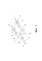
Заявляемое изобретение иллюстрируется фигурами 1 и 2 с использованием следующих обозначений:The claimed invention is illustrated by figures 1 and 2 using the following notation:
1 - линейный участок;1 - linear section;
2 - вспомогательный трубопровод;2 - auxiliary pipeline;
3 - клапан;3 - valve;
4 - трубопроводный элемент Z-образной формы;4 - Z-shaped pipeline element;
5 - фланец;5 - flange;
6 - устройство для временной фиксации фланцевых заглушек$6 - device for temporary fixation of flange plugs $
7 - положение подключения водяного пара;7 - position of connection of water vapor;
8 - положение подключения инертного газа;8 - inert gas connection position;
9 - положение отключения участка.9 - section shutdown position.
Линейный участок 1 системы сборно-разборных трубопроводов с одной стороны подключен к ремонтируемому оборудованию (на фигуре не указан), а с другой с помощью фланца 5 - к трубопроводному элементу Z-образной формы 4. В свою очередь, трубопроводный элемент Z-образной формы 4 подключается через клапан 3 к трассе вспомогательных трубопроводов 2, куда из общезаводских трубопроводов поступают вода, водяной пар, инертный газ и другие вспомогательные потоки для проведения соответствующих операций.The linear section 1 of the system of collapsible pipelines is connected on the one hand to the equipment being repaired (not shown in the figure), and on the other hand, with the help of a
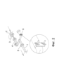
На фигуре 2 трубопроводный элемент Z-образной формы 4 дополнительно оснащен устройством для временной фиксации фланцевых заглушек 6 на время подключения элемента к одному из вспомогательных трубопроводов 2.In figure 2, the Z-
Таким образом, разработанная система стальных сборно-разборных трубопроводов обеспечивает временные заводские трубопроводные системы, связывая технологическое оборудование с трубопроводами подачи вспомогательных потоков на время проведения ремонтных работ.Thus, the developed system of steel collapsible pipelines provides temporary factory pipeline systems, connecting process equipment with pipelines for supplying auxiliary flows for the period of repair work.
Claims (3)
Publications (1)
| Publication Number | Publication Date |
|---|---|
| RU2794271C1 true RU2794271C1 (en) | 2023-04-13 |
Family
ID=
Citations (5)
| Publication number | Priority date | Publication date | Assignee | Title |
|---|---|---|---|---|
| RU11588U1 (en) * | 1999-05-05 | 1999-10-16 | Общество с ограниченной ответственностью Научно-производственное предприятие "ИМПУЛЬС" | GAS PUMPING SYSTEM FROM A MAIN PIPELINE SECTION |
| RU29117U1 (en) * | 2001-11-02 | 2003-04-27 | ООО "Ненецкий научно-исследовательский и проектно-изыскательский институт нефтяной промышленности" | Pipeline system for transporting oil, or oil products, or water |
| RU69193U1 (en) * | 2007-08-06 | 2007-12-10 | Ооо "Нефтегаз Инжиниринг" | ASSEMBLY AND DISASSEMBLY PIPELINE SYSTEM FOR TRANSPORTATION OF OIL, OIL PRODUCTS, WATER |
| RU119058U1 (en) * | 2012-03-22 | 2012-08-10 | Министерство образования и науки Российской Федерации Федеральное государственное бюджетное образовательное учреждение высшего профессионального образования Уфимский государственный авиационный технический университет | TEMPORARY PIPELINE FOR PUMPING-PUMPING OIL AND OIL PRODUCTS WHEN REPAIRING PIPELINES |
| RU2543921C1 (en) * | 2014-03-05 | 2015-03-10 | Федеральное автономное учреждение "25 Государственный научно-исследовательский институт химмотологии Министерства обороны Российской Федерации" | Linear element of demountable pipeline |
Patent Citations (5)
| Publication number | Priority date | Publication date | Assignee | Title |
|---|---|---|---|---|
| RU11588U1 (en) * | 1999-05-05 | 1999-10-16 | Общество с ограниченной ответственностью Научно-производственное предприятие "ИМПУЛЬС" | GAS PUMPING SYSTEM FROM A MAIN PIPELINE SECTION |
| RU29117U1 (en) * | 2001-11-02 | 2003-04-27 | ООО "Ненецкий научно-исследовательский и проектно-изыскательский институт нефтяной промышленности" | Pipeline system for transporting oil, or oil products, or water |
| RU69193U1 (en) * | 2007-08-06 | 2007-12-10 | Ооо "Нефтегаз Инжиниринг" | ASSEMBLY AND DISASSEMBLY PIPELINE SYSTEM FOR TRANSPORTATION OF OIL, OIL PRODUCTS, WATER |
| RU119058U1 (en) * | 2012-03-22 | 2012-08-10 | Министерство образования и науки Российской Федерации Федеральное государственное бюджетное образовательное учреждение высшего профессионального образования Уфимский государственный авиационный технический университет | TEMPORARY PIPELINE FOR PUMPING-PUMPING OIL AND OIL PRODUCTS WHEN REPAIRING PIPELINES |
| RU2543921C1 (en) * | 2014-03-05 | 2015-03-10 | Федеральное автономное учреждение "25 Государственный научно-исследовательский институт химмотологии Министерства обороны Российской Федерации" | Linear element of demountable pipeline |
Similar Documents
| Publication | Publication Date | Title |
|---|---|---|
| US20020038954A1 (en) | Protected welded joint for fluid transport pipes and its manufacturing process | |
| US3351361A (en) | Insulated piping system | |
| CN208859146U (en) | A kind of crossover flange with neck containing sealing structure | |
| RU2557154C1 (en) | Dismountable heat exchanger | |
| RU2794271C1 (en) | System of steel collapsible pipelines | |
| US20110241342A1 (en) | Pipe Repair Clamp with Self Pressurizing Seal | |
| RU2724093C1 (en) | Pipeline system for fire extinguishing | |
| Vasquez | COST | |
| CN101352603B (en) | Automatic spray conduit system and installation method thereof | |
| KR100938901B1 (en) | How to repair plumbing system | |
| RU99098U1 (en) | INTERIOR COUPLING STRUCTURE DESIGN | |
| RU214763U1 (en) | CORROSION-RESISTANT (STAINLESS) STEEL FIXED SUPPORT | |
| US20120049515A1 (en) | Boltless Pipe Joint Assembly | |
| WO2012030307A1 (en) | Innovation in assembly – disassembly systems and o-ring groove of plastic pipe fitting couplings | |
| KR20210039240A (en) | The joint pipe for preventing stagnant water | |
| WO2025037155A1 (en) | Welded clamp to repair an active pipe leakage | |
| KR20220010853A (en) | A valve union | |
| Murakami et al. | WJC-E 7334A | |
| CN220286738U (en) | Acid and alkali resistant multipath connection device | |
| RU138519U1 (en) | ELEMENT OF STEEL PIPELINE (OPTIONS) | |
| CN222163896U (en) | Bolt compensation type corrugated pipe | |
| CN223563670U (en) | Bearing type PE drain pipe | |
| Herckis | Specifications, Procedures, and Fittings for Tapping and Plugging to Achieve Effective Pipeline Modification and Repair | |
| Pipe et al. | SECTION 22 10 00-PLUMBING PIPING | |
| CN121273996A (en) | A pipe sealing device and sealing method |