RU2781663C1 - Cone dryer - Google Patents
Cone dryer Download PDFInfo
- Publication number
- RU2781663C1 RU2781663C1 RU2022102257A RU2022102257A RU2781663C1 RU 2781663 C1 RU2781663 C1 RU 2781663C1 RU 2022102257 A RU2022102257 A RU 2022102257A RU 2022102257 A RU2022102257 A RU 2022102257A RU 2781663 C1 RU2781663 C1 RU 2781663C1
- Authority
- RU
- Russia
- Prior art keywords
- heat
- insulated chamber
- perforated
- cones
- coolant
- Prior art date
Links
- 238000001035 drying Methods 0.000 claims abstract description 24
- 230000003247 decreasing effect Effects 0.000 claims abstract description 6
- 239000002826 coolant Substances 0.000 claims description 18
- 230000000694 effects Effects 0.000 abstract 1
- 239000000126 substance Substances 0.000 abstract 1
- 238000009434 installation Methods 0.000 description 3
- XLYOFNOQVPJJNP-UHFFFAOYSA-N water Substances O XLYOFNOQVPJJNP-UHFFFAOYSA-N 0.000 description 3
- 238000007664 blowing Methods 0.000 description 2
- 241000218631 Coniferophyta Species 0.000 description 1
- 238000005265 energy consumption Methods 0.000 description 1
- 230000005484 gravity Effects 0.000 description 1
- 238000010438 heat treatment Methods 0.000 description 1
- 238000012423 maintenance Methods 0.000 description 1
- 239000000463 material Substances 0.000 description 1
Images
Abstract
Description
Техническое решение относится к лесохозяйственной технике, в частности, к устройствам для сушки шишек хвойных деревьев с целью извлечения из них семян.The technical solution relates to forestry equipment, in particular, to devices for drying cones of coniferous trees in order to extract seeds from them.
Известна шишкосушилка [Патент РФ №163962, опубл. 20.08.2016], которая включает теплоизолированную камеру в виде шкафа с дверями, многоярусный стеллаж с полками для сушильных ящиков, электрический водонагреватель с автоматическим управлением температурой, устройство для подачи теплоносителя в зону сушки, распределитель теплоносителя и вытяжной вентилятор. Устройство для подачи теплоносителя в зону сушки выполнено в виде циркуляционного насоса. Распределитель теплоносителя выполнен в виде горизонтальных трубчатых теплообменников, которые используются в качестве полок для сушильных ящиков. Все полки последовательно соединены между собой водонагревателем и циркуляционным насосом, образуя единый замкнутый контур для обеспечения циркуляции воды.Known cone dryer [RF Patent No. 163962, publ. 08/20/2016], which includes a heat-insulated chamber in the form of a cabinet with doors, a multi-tiered rack with shelves for drying boxes, an electric water heater with automatic temperature control, a device for supplying coolant to the drying zone, a coolant distributor and an exhaust fan. The device for supplying the heat carrier to the drying zone is made in the form of a circulation pump. The heat carrier distributor is made in the form of horizontal tubular heat exchangers, which are used as shelves for drying boxes. All shelves are connected in series with each other by a water heater and a circulation pump, forming a single closed loop to ensure water circulation.
Однако такая шишкосушилка имеет ряд недостатков, к которым можно отнести: значительные потери теплоты, сложность конструкции и низкое качество сушки шишек.However, such a cone dryer has a number of disadvantages, which include: significant heat loss, design complexity and poor quality of cone drying.
Технический результат, достигаемый при использовании изобретения - снижение затрат энергии на сушку, повышение качества сушки шишек и упрощение конструкции.The technical result achieved by using the invention is to reduce energy costs for drying, improve the quality of drying cones and simplify the design.
Технический результат достигается тем, что устройство для подачи теплоносителя в зону сушки выполняют в виде центробежного вентилятора. Распределитель теплоносителя выполняют в виде горизонтально установленной перфорированной трубы, которую снабжают установленными радиально по винтовой линии и на равном расстоянии друг от друга перфорированными патрубками, внутренняя полость которых сообщается с внутренней полостью перфорированной трубы. Отверстия в перфорированных патрубках выполняют с уменьшающимися размерами от места прикрепления перфорированных патрубков к их концу. Емкость для шишек выполняют в виде сетчатого барабана, снабженного съемными створками. Сетчатый барабан устанавливают в теплоизолированной камере как с возможностью вращения вокруг перфорированной трубы, так и с возможностью изменения частоты вращения. Привод вентилятора выполняют с регулируемой частотой вращения. В верхней части боковых сторон теплоизолированной камеры устанавливают выпускные патрубки. Теплоизолированную камеру устанавливают на стойках, а двери устанавливают как в верхней, так и в нижней частях теплоизолированной камеры.The technical result is achieved by the fact that the device for supplying the coolant to the drying zone is made in the form of a centrifugal fan. The coolant distributor is made in the form of a horizontally installed perforated pipe, which is provided with perforated branch pipes installed radially along a helical line and at an equal distance from each other, the internal cavity of which communicates with the internal cavity of the perforated pipe. The holes in the perforated pipes are made with decreasing size from the point of attachment of the perforated pipes to their end. The container for cones is made in the form of a mesh drum equipped with removable flaps. The mesh drum is installed in a heat-insulated chamber both with the possibility of rotation around the perforated pipe, and with the possibility of changing the speed of rotation. The fan drive is performed with an adjustable speed. In the upper part of the sides of the heat-insulated chamber, outlet pipes are installed. The thermally insulated chamber is installed on racks, and the doors are installed both in the upper and lower parts of the thermally insulated chamber.
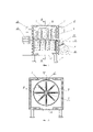
На фиг. 1 изображен общий вид шишкосушилки, на фиг. 2 - то же, разрез по А - А.In FIG. 1 shows a general view of the cone dryer, Fig. 2 - the same, section along A - A.
Шишкосушилка состоит из теплоизолированной камеры 1, выполненной в виде установленного на стойках 2 шкафа с дверями 3 и 4, установленными соответственно в верхней и нижней частях теплоизолированной камеры 1, электрического нагревателя 5 теплоносителя с автоматическим управлением температурой, устройства для подачи теплоносителя в зону сушки, выполненного в виде центробежного вентилятора 6, распределителя теплоносителя, выполненного в виде установленной горизонтально перфорированной трубы 7, снабженной установленными радиально по винтовой линии и на равном расстоянии друг от друга перфорированными патрубками 8, внутренняя полость которых сообщается с внутренней полостью перфорированной трубы 7, и емкости для шишек, которая выполнена в виде сетчатого барабана 9, снабженного съемными створками 10 и установленного в теплоизолированной камере 1 с возможностью вращения вокруг перфорированной трубы 7, а также с возможностью изменения частоты вращения. Отверстия в перфорированных патрубках 8 выполнены с уменьшающимися размерами от места прикрепления перфорированных патрубков 8 к их концу. Центробежный вентилятор 6 соединен с перфорированной трубой 7 воздуховодом 11, в котором установлен электрический нагреватель 5 теплоносителя. Привод вентилятора 6 выполнен с регулируемой частотой вращения. В верхней части боковых сторон теплоизолированной камеры 1 установлены выпускные патрубки 12. Сетчатый барабан 9 вращается вокруг перфорированной трубы 7 от привода 13. Изменение частоты вращения сетчатого барабана 9 может достигаться, например, использованием в приводе 13 асинхронного электродвигателя вместе с преобразователем частоты питающего тока. Аналогичным образом можно регулировать частоту вращения привода центробежного вентилятора 6.The cone dryer consists of a heat-insulated
Шишкосушилка работает следующим образом. Открывают двери 3, установленные в верхней части теплоизолированной камеры 1. Открывают съемные створки 10 и заполняют шишками сетчатый барабан 9. Затем съемные створки 10 закрывают и также закрывают двери 3. Включают привод 13, с помощью которого сетчатый барабан 9 начинает вращаться вокруг установленной горизонтально перфорированной трубы 7. Включают центробежный вентилятор 6 и электрический нагреватель 5. Нагретый теплоноситель (воздух) поступает через воздуховод 11 в перфорированную трубу 7 и установленные радиально по винтовой линии и на равном расстоянии друг от друга перфорированные патрубки 8, затем проходит через отверстия перфорированной трубы 7 и перфорированных патрубков 8, а далее - через слой шишек, находящихся в сетчатом барабане 9, нагревая их и удаляя из них влагу. При вращении сетчатого барабана 9 установленные радиально по винтовой линии и на равном расстоянии друг от друга перфорированные патрубки 8 дополнительно перемешивают находящиеся в сетчатом барабане 9 шишки, повышая равномерность этого перемешивания, а равномерность обдува шишек теплоносителем повышается за счет выполнения отверстий в перфорированных патрубках 8 с уменьшающимися размерами от места прикрепления перфорированных патрубков 8 к их концу. Влажный воздух удаляется из теплоизолированной камеры 1 через выпускные патрубки 12, установленные в верхней части боковых сторон теплоизолированной камеры 1. После окончания процесса сушки отключают электрический нагреватель 5 и центробежный вентилятор 6, привод 13 останавливают и открывают двери 3. Затем открывают двери 4, установленные в нижней части теплоизолированной камеры 1. Открывают съемные створки 10, а сетчатый барабан 9 поворачивают на 180 градусов таким образом, чтобы открытый проем в сетчатом барабане 9, образовавшийся после открывания съемных створок 10, был направлен вниз. Под действием силы тяжести высушенные шишки падают вниз, освобождая сетчатый барабан 9. После этого процесс сушки повторяется.Shishkosushilka works as follows.
При использовании шишек других хвойных деревьев с помощью устройства автоматического управления изменяют температуру теплоносителя, управляя мощностью электрического нагревателя 5, а также изменяют частоты вращения сетчатого барабана 9 и центробежного вентилятора 6, что обеспечивает требуемое качество сушки при низких затратах энергии.When using the cones of other coniferous trees, the automatic control device changes the temperature of the coolant by controlling the power of the
Установка сетчатого барабана 9 в теплоизолированной камере 1 как с возможностью вращения вокруг перфорированной трубы 7, так и с возможностью изменения частоты вращения, выполнение привода вентилятора 6 с регулируемой частотой вращения позволяет обеспечить легкое изменение режимов сушки при различной исходной влажности партий обрабатываемых шишек, а также при необходимости сушить шишки разных хвойных деревьев.Installing a mesh drum 9 in a heat-insulated
Выполнение устройства для подачи теплоносителя в зону сушки в виде центробежного вентилятора позволяет обеспечить достаточный напор воздуха для его прохождения через слой шишек. Выполнение распределителя теплоносителя в виде установленной горизонтально перфорированной трубы, снабженной установленными радиально по винтовой линии и на равном расстоянии друг от друга перфорированными патрубками, внутренняя полость которых сообщается с внутренней полостью перфорированной трубы, выполнение отверстий в патрубках с уменьшающимися размерами от места прикрепления патрубков к их концу - все это обеспечивает равномерную подачу теплоносителя в высушиваемый материал по всем радиальным направлениям сетчатого барабана. Выполнение емкости для шишек в виде сетчатого барабана, установленного в теплоизолированной камере с возможностью вращения вокруг перфорированной трубы, повышает равномерность обдува шишек теплоносителем как за счет вращения сетчатого барабана, так и за счет изменения положения шишек при его вращении и действии на шишки перфорированных патрубков.The implementation of the device for supplying the coolant to the drying zone in the form of a centrifugal fan allows you to provide sufficient air pressure to pass through the layer of cones. Execution of the coolant distributor in the form of a horizontally installed perforated pipe, equipped with perforated pipes installed radially along a helical line and at an equal distance from each other, the internal cavity of which communicates with the internal cavity of the perforated pipe, making holes in the pipes with decreasing dimensions from the place of attachment of the pipes to their end - all this ensures a uniform supply of the coolant to the material to be dried in all radial directions of the mesh drum. Execution of the container for cones in the form of a mesh drum installed in a heat-insulated chamber with the possibility of rotation around the perforated pipe increases the uniformity of blowing the cones with the coolant both due to the rotation of the mesh drum and by changing the position of the cones during its rotation and the action of the perforated pipes on the cones.
Снабжение сетчатого барабана съемными створками, установка в верхней и нижней частях теплоизолированной камеры дверей, а также установка теплоизолированной камеры на стойках, все это при простоте конструкции обеспечивает легкую загрузку и выгрузку шишек, а также упрощает доступ к элементам шишкосушилки при ее техническом обслуживании.The supply of the mesh drum with removable shutters, the installation of doors in the upper and lower parts of the heat-insulated chamber, as well as the installation of the heat-insulated chamber on racks, all this, with a simple design, provides easy loading and unloading of cones, and also simplifies access to the elements of the cone dryer during its maintenance.
Установка в верхней части боковых сторон теплоизолированной камеры выпускных патрубков обеспечивает качественное удаление отработанного теплоносителя. Таким образом, предлагаемая шишкосушилка снижает энергоемкость процесса сушки, повышает качества сушки шишек при более простом конструктивном исполнении.The installation of outlet pipes in the upper part of the sides of the heat-insulated chamber ensures high-quality removal of the spent coolant. Thus, the proposed cone dryer reduces the energy consumption of the drying process, improves the quality of drying cones with a simpler design.
Claims (1)
Publications (1)
| Publication Number | Publication Date |
|---|---|
| RU2781663C1 true RU2781663C1 (en) | 2022-10-17 |
Family
ID=
Citations (4)
| Publication number | Priority date | Publication date | Assignee | Title |
|---|---|---|---|---|
| RU2216700C1 (en) * | 2002-03-19 | 2003-11-20 | Никоноров Сергей Николаевич | Drier for loose thermally sensitive materials ( variants ) |
| RU2364808C2 (en) * | 2007-05-03 | 2009-08-20 | Андрей Николаевич Серов | Dryer drum |
| RU163962U1 (en) * | 2015-11-03 | 2016-08-20 | Анатолий Александрович Головин | DRYER DRYER |
| RU2680709C1 (en) * | 2017-12-20 | 2019-02-25 | Федеральное государственное бюджетное образовательное учреждение высшего образования "Чувашская государственная сельскохозяйственная академия" | Hops initial post-harvest processing system |
Patent Citations (4)
| Publication number | Priority date | Publication date | Assignee | Title |
|---|---|---|---|---|
| RU2216700C1 (en) * | 2002-03-19 | 2003-11-20 | Никоноров Сергей Николаевич | Drier for loose thermally sensitive materials ( variants ) |
| RU2364808C2 (en) * | 2007-05-03 | 2009-08-20 | Андрей Николаевич Серов | Dryer drum |
| RU163962U1 (en) * | 2015-11-03 | 2016-08-20 | Анатолий Александрович Головин | DRYER DRYER |
| RU2680709C1 (en) * | 2017-12-20 | 2019-02-25 | Федеральное государственное бюджетное образовательное учреждение высшего образования "Чувашская государственная сельскохозяйственная академия" | Hops initial post-harvest processing system |
Similar Documents
| Publication | Publication Date | Title |
|---|---|---|
| RU2781663C1 (en) | Cone dryer | |
| RU2780912C1 (en) | Cone dryer | |
| RU2783847C1 (en) | Cone dryer | |
| RU2781672C1 (en) | Cone dryer | |
| RU2781667C1 (en) | Cone dryer | |
| RU2781662C1 (en) | Cone dryer | |
| RU2781664C1 (en) | Cone dryer | |
| RU2781668C1 (en) | Cone dryer | |
| RU2781666C1 (en) | Cone dryer | |
| RU2779082C1 (en) | Cone dryer | |
| US2098066A (en) | Treating apparatus | |
| CN206989622U (en) | A kind of drum type brake baked seed equipment with two-layer equation drying plate | |
| CN108826912A (en) | A kind of textile fabric drying box | |
| KR102392052B1 (en) | Agricultural drier with air blow reversing device | |
| RU2779107C1 (en) | Cone dryer | |
| RU2781660C1 (en) | Cone dryer | |
| CN209415943U (en) | A kind of novel dehumidifying exhaust fan | |
| RU98674U1 (en) | PLANT FOR DRYING VEGETABLE RAW MATERIALS AND ROOTS | |
| RU2779106C1 (en) | Cone dryer | |
| CN211926378U (en) | Novel drying-machine is used in tea-oil camellia processing | |
| CN205337440U (en) | Tea wrap device of easy control | |
| CN223525481U (en) | A vegetable seed dehydration and drying equipment | |
| CN207936719U (en) | A kind of drying system | |
| EP0281525B1 (en) | Apparatus for the dyeing of yarn hanks in short bath and the drying thereof | |
| RU2208341C2 (en) | Macaroni product drying cabinet |