RU2775503C1 - Centrifugal drencher nozzle - Google Patents
Centrifugal drencher nozzle Download PDFInfo
- Publication number
- RU2775503C1 RU2775503C1 RU2021125363A RU2021125363A RU2775503C1 RU 2775503 C1 RU2775503 C1 RU 2775503C1 RU 2021125363 A RU2021125363 A RU 2021125363A RU 2021125363 A RU2021125363 A RU 2021125363A RU 2775503 C1 RU2775503 C1 RU 2775503C1
- Authority
- RU
- Russia
- Prior art keywords
- cast
- swirler
- chamber
- diffuser
- neck
- Prior art date
Links
- XLYOFNOQVPJJNP-UHFFFAOYSA-N water Substances O XLYOFNOQVPJJNP-UHFFFAOYSA-N 0.000 claims description 9
- 239000003795 chemical substances by application Substances 0.000 claims description 6
- 230000035622 drinking Effects 0.000 claims description 4
- 239000004033 plastic Substances 0.000 claims description 3
- 239000004734 Polyphenylene sulfide Substances 0.000 claims description 2
- 229920000069 polyphenylene sulfide Polymers 0.000 claims description 2
- 239000007788 liquid Substances 0.000 abstract description 4
- 238000009434 installation Methods 0.000 abstract description 2
- 238000009827 uniform distribution Methods 0.000 abstract description 2
- 239000000126 substance Substances 0.000 abstract 1
- 230000002093 peripheral effect Effects 0.000 description 5
- 239000000243 solution Substances 0.000 description 5
- 238000005507 spraying Methods 0.000 description 5
- 239000003651 drinking water Substances 0.000 description 3
- 235000020188 drinking water Nutrition 0.000 description 3
- 238000004519 manufacturing process Methods 0.000 description 2
- 238000000034 method Methods 0.000 description 2
- 230000015572 biosynthetic process Effects 0.000 description 1
- 239000012530 fluid Substances 0.000 description 1
- 238000001746 injection moulding Methods 0.000 description 1
- 230000002262 irrigation Effects 0.000 description 1
- 238000003973 irrigation Methods 0.000 description 1
- 238000003908 quality control method Methods 0.000 description 1
- 238000000926 separation method Methods 0.000 description 1
- 239000007921 spray Substances 0.000 description 1
- 239000008399 tap water Substances 0.000 description 1
- 235000020679 tap water Nutrition 0.000 description 1
- 229920001169 thermoplastic Polymers 0.000 description 1
- 239000004416 thermosoftening plastic Substances 0.000 description 1
- 239000002699 waste material Substances 0.000 description 1
Images
Abstract
Description
Предлагаемое техническое решение относится к противопожарной технике и может применяться в установках пожаротушения при защите от пожара в жилых помещениях, обеспечивая равномерное распределение потока жидкости при рабочем давлении от 0,05 МПа.The proposed technical solution relates to fire fighting equipment and can be used in fire extinguishing installations for fire protection in residential premises, providing a uniform distribution of fluid flow at an operating pressure of 0.05 MPa.
Из уровня техники известно много устройств, использующих центробежные силы потоков жидкости для создания равномерно распределенного распыленного потока жидкости по защищаемой площади.In the prior art, many devices are known that use the centrifugal forces of liquid flows to create a uniformly distributed atomized liquid flow over the area to be protected.
В качестве аналогов рассмотрены: центробежный распылитель RU 30275, распылитель RU 90692, ороситель центробежный RU 2297865.The following are considered as analogues: centrifugal atomizer RU 30275, atomizer RU 90692, centrifugal sprinkler RU 2297865.
В настоящее вермя широко используется для распределения по защищаемой поверхности распыленного потока огнетушащего вещества (ОТВ) распылитель центробежный «РЦ-180», выпускаемый ЗАО «ПО «Спецавтоматика», г. Бийск, в основу конструкции которого заложен патент на изобретение RU 2297865.At present, the RC-180 centrifugal sprayer, produced by CJSC PO Spetsavtomatika, Biysk, is widely used to distribute the sprayed flow of a fire extinguishing agent (FTE) over the protected surface, the design of which is based on the patent for the invention RU 2297865.
Известный распылитель содержит корпус, втулку и вкладыш с нанесенными на их внешние поверхности винтовыми каналами; между корпусом в втулкой образована одна вихревая камера, имеющая входные отверстия и выходное отверстие, а между втулкой и вкладышем создана другая вихревая камера, имеющая свои входные отверстия и выходное отверстие.Known atomizer contains a housing, a sleeve and an insert with screw channels applied to their outer surfaces; between the body in the sleeve, one vortex chamber is formed, having inlets and an outlet, and between the sleeve and the liner, another vortex chamber is created, having its own inlets and an outlet.
Наличие двух концентрично расположенных вихревых камер позволяет формировать два концентрично расположенных вихревых факела распыла ОТВ, обеспечивающих равномерное орошение защищаемой площади.The presence of two concentrically located vortex chambers makes it possible to form two concentrically located vortex flames of the OTV spray, providing uniform irrigation of the protected area.
В другом известном распылителе жидкости, выполненном по патенту на полезную модель RU 90692, равномерное распыление по защищаемой поверхности обеспечивается формированием распыленных внутреннего и внешнего факелов ОТВ, при этом внутренний факел создан посредством прямоточного центрального распылителя с розеткой на выходе, а внешний факел выполнен на периферии потока ОТВ посредством проходной камеры, выполненной внутренней и внешней воронками, которые соосны со штуцером.In another well-known liquid atomizer, made according to the utility model patent RU 90692, uniform spraying over the protected surface is ensured by the formation of sprayed internal and external torches of OTV, while the inner torch is created by means of a direct-flow central atomizer with a socket at the outlet, and the outer torch is made on the periphery of the flow OTV through a passage chamber made with internal and external funnels, which are coaxial with the fitting.
В известном оросителе центробежном, выполненном по патенту на изобретение RU 2297865, центробежные силы, действующие на поток ОТВ, заданы посредством выполнения вводного устройства в виде тангенциального патрубка, соединенного с корпусом с сердечником, и закрепленную на корпусе насадок, имеющий центральный и боковые отверстия и конусный отражатель.In the well-known centrifugal sprinkler, made according to the invention patent RU 2297865, the centrifugal forces acting on the flow of FTV are set by making an inlet device in the form of a tangential pipe connected to the body with a core, and fixed on the body of the nozzle, having a central and side holes and a conical reflector.
Применение аналогов не гарантирует, в случае подключения их к источникам воды с рабочим давлением 0,05 МПа, эффективное тушение. Кроме того анализ известных вышеописанных устройств показал, что для реализации этих устройств требуется использование сложных и трудоемких технологических способов, что сказывается на себестоимости продукции.The use of analogues does not guarantee, if they are connected to water sources with a working pressure of 0.05 MPa, effective extinguishing. In addition, the analysis of the known devices described above showed that the implementation of these devices requires the use of complex and labor-intensive technological methods, which affects the cost of production.
На потребительском рынке мало насадков и оросителей, известных в качестве устройств сравнительно дешевых и способных эффективно осуществлять тушение в жилых помещениях, в случаях использования для тушения воды, получаемой из водопровода хозяйственно-питьевого назначения, в котором рабочий диапозон давления часто начинается от 0,05 МПа.There are few nozzles and sprinklers on the consumer market, known as devices that are relatively cheap and capable of effectively extinguishing in residential premises, in cases where they are used to extinguish water obtained from a drinking water supply system, in which the operating pressure range often starts from 0.05 MPa .
При создании изобретения ставится задача по расширению арсенала технических средств, а именно: включение в арсенал технических средств насадков дренчерных цетробежных, способных при тушении эффективно распылять ОТВ, включая водопроводную воду, получаемую при рабочем давлении ОТВ от 0,05 МПа из водопровода хозяйственно-питьевого назначения.When creating the invention, the task is to expand the arsenal of technical means, namely: the inclusion in the arsenal of technical means of deluge centrifugal nozzles capable of effectively spraying fire extinguishing agents, including tap water obtained at an operating pressure of fire extinguishing agents from 0.05 MPa from a drinking water supply .
Технический результат должен заключаться в реализации заявленного назначения, а именно: проявляться в возможности функционировать как противопожарное устройство при использовании в качестве ОТВ воды, получаемой из водопровода сети хозяйственно-питьевого назначения с рабочим давлением от 0,05 МПа, равномерно распыляя ее по защищаемой поверхности. Известные аналоги не способны выполнять такую функцию.The technical result should consist in the implementation of the declared purpose, namely: to manifest itself in the ability to function as a fire-fighting device when using water obtained from the water supply of a household and drinking network with a working pressure of 0.05 MPa as an extinguishing agent, spraying it evenly over the protected surface. Known analogues are not capable of performing such a function.
Поставленная задача решается насадком дренчерным центробежным, который характеризуется при его активации действием от водопроводной сети хозяйственно-питьевого назначения с рабочим давлением ОТВ от 0,05 МПа, выполнением пустотелого корпуса, который имеет входную нижнюю часть с наружной присоединительной резьбой, имеет шестигранник, выполненный на средней части корпуса, имеет внутри корпуса выходную часть, выполненную в виде диффузора, при этом внутри корпуса входная нижняя часть выполнена в виде конфузора, в котором концентрично относительно оси корпуса расположен литой завихритель с размещенным в нем литым вкладышем, над завихрителем в корпусе выполнена камера, выход из камеры выполнен через горловину определенной формы, которая характеризуется отношением высоты горловины к ее диаметру приблизительно равным 1:5; горловина плавно сопряжена с диффузором, завихритель выполнен в виде пустотелой литой втулки, у которой на внешней нижней цилиндрической части выполнена левая трапецеидальная четырехзаходная резьба, нижняя цилиндрическая часть литого завихрителя плавно переходит в верхнюю сферическую часть, которая сопрягается с верхней цилиндрической частью, при этом диаметр нижней цилиндрической части завихрителя больше диаметра его верхней цилиндрической части в 1,7 раза, внутри в нижней цилиндрической части литого завихрителя выполнена цилиндрическая полость, переходящая в средней части литого завихрителя в полость, выполненную в виде усеченного конуса, при этом угол схождения боковой стенки усеченного конуса приблизительно равен 23°, верхняя часть этой конусоидальной полости посредством небольшого диффузора сообщена с камерой, в цилиндрической полости литого завихрителя установлен литой вкладыш, выполненный в виде центральной двухзаходной для потока ОТВ направляющей детали с правым направлением, при этом каждый ход направляющей детали выполнен в виде нижней наклонной плоскости, переходящей в горизонтальную ступень, которая переходит в верхнюю наклонную плоскость.The task is solved by a centrifugal deluge nozzle, which, when activated, is characterized by the action from the water supply network for household and drinking purposes with an operating pressure of OTV from 0.05 MPa, the implementation of a hollow body, which has an inlet lower part with an external connecting thread, has a hexagon, made on the middle part of the housing, has an outlet part inside the housing, made in the form of a diffuser, while inside the housing the inlet lower part is made in the form of a confuser, in which a cast swirler with a cast insert placed in it is located concentrically with respect to the axis of the housing, a chamber is made above the swirler in the housing, the outlet from the chamber is made through a neck of a certain shape, which is characterized by a ratio of the height of the neck to its diameter of approximately 1:5; the neck is smoothly mated with the diffuser, the swirler is made in the form of a hollow cast bushing, in which a left-hand trapezoidal four-start thread is made on the outer lower cylindrical part, the lower cylindrical part of the cast swirler smoothly passes into the upper spherical part, which mates with the upper cylindrical part, while the diameter of the lower cylindrical part of the swirler is 1.7 times larger than the diameter of its upper cylindrical part, inside in the lower cylindrical part of the cast swirler a cylindrical cavity is made, passing in the middle part of the cast swirler into a cavity made in the form of a truncated cone, while the angle of convergence of the side wall of the truncated cone is approximately is equal to 23°, the upper part of this cone-shaped cavity is connected with the chamber by means of a small diffuser, a cast insert is installed in the cylindrical cavity of the cast swirler, made in the form of a central two-way guide for the flow of the ETV with the right direction, n At the same time, each stroke of the guide part is made in the form of a lower inclined plane, turning into a horizontal step, which turns into an upper inclined plane.
Корпус, завихритель, вкладыш могут быть выполнены из полифениленсульфида ТЕРМОРАН ПФС СВ - 40 ТУ 2016.59-001-01531596-2018, представляющего собой пластическую массу.The body, swirler, insert can be made of polyphenylene sulfide TERMORAN PFS SV - 40 TU 2016.59-001-01531596-2018, which is a plastic mass.
Способ изготовления деталей может быть осуществлен высокопроизводительно, малозатратно, практически безотходно, с применением широко применяемых термопласт - автоматов.The method of manufacturing parts can be carried out highly productively, at low cost, practically without waste, using widely used thermoplastic machines.
Предлагаемый насадок дренчерный центробежный состоит из простых трех деталей, выполненных в виде форм тел вращения, не имеющих внутри себя тупиковых и замкнутых полостей, выполненных, из пластмассы методом литья под давлением, при этом сборка деталей, контроль качества деталей и самого насадка легко осуществимы.The proposed centrifugal deluge nozzle consists of simple three parts, made in the form of bodies of rotation, without dead-end and closed cavities inside, made of plastic by injection molding, while the assembly of parts, quality control of parts and the nozzle itself are easily feasible.
Таким образом заявляемое техническое решение соответствует критерию «промышленная применимость».Thus, the claimed technical solution meets the criterion of "industrial applicability".
Впервые в предлагаемом техническом решении проявляется возможность его использования, при обеспечении защиты от пожара жилых помещений, путем подачи воды в качестве ОТВ при сравнительно низком давлении (от 0,05 МПа) от источника воды хозяйственно-питьевого назначения, обеспечивая равномерное распыление воды по защищаемой поверхности, при этом новым в техническом решении являются конструкции всех трех деталей, которые образуют насадок и при активации насадка обеспечивают новую оригинальную комбинацию разнонаправленных потоков ОТВ как внутри насадка, так и на выходе из него.For the first time in the proposed technical solution, the possibility of its use is manifested, when providing fire protection for residential premises, by supplying water as a fire extinguishing agent at a relatively low pressure (from 0.05 MPa) from a source of drinking water, ensuring uniform spraying of water over the protected surface , while new in the technical solution are the designs of all three parts that form the nozzle and, when the nozzle is activated, provide a new original combination of multidirectional OTV flows both inside the nozzle and at the exit from it.
Поступающей в насадок поток ОТВ разделяется на разнонаправленные завихряющиеся периферийный и центральный потоки.The flow of OTV entering the nozzle is divided into differently directed swirling peripheral and central flows.
Периферийный поток, проходя по винтовым каналам между корпусом и завихрителем, получает поступательную и угловую левонаправленную составляющие скорости потока. Центральный поток, проходя в нижней цилиндрической части завихрителя по центральной двухзаходной правонаправляющей детали (вкладышу), поступает в сужающееся пространство завихрителя. Оба потока встречаются в камере, при этом имеют разные скорости, как вдоль общей оси движения, так и угловые. Далее периферийный и центральный потоки, проходя через горловину, поступают в диффузор, что сопровождается резким перепадом давления, отрывом потока от корпуса, дроблением потоков ОТВ и равномерным распылением по защищаемой поверхности.The peripheral flow, passing through the helical channels between the housing and the swirler, receives the translational and angular left-hand components of the flow velocity. The central flow, passing in the lower cylindrical part of the swirler along the central two-way right-hand guide part (liner), enters the narrowing space of the swirler. Both streams meet in the chamber, while they have different velocities, both along the common axis of motion and angular. Further, the peripheral and central flows, passing through the neck, enter the diffuser, which is accompanied by a sharp pressure drop, separation of the flow from the housing, crushing of the FTA flows and uniform spraying over the protected surface.
В наилучшем варианте исполнения изображения насадокIn the best version of the image of the nozzles
На основе вышеизложенного можно утверждать о соответствии технического решения критерию «новизна».Based on the foregoing, it can be argued that the technical solution meets the criterion of "novelty".
Более подробно изобретение описывается с опорой на чертежи, где:The invention is described in more detail with reference to the drawings, where:
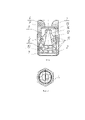
Фиг. 1 - общий вид насадка дренчерного центробежного в разрезе.Fig. 1 - a general view of the centrifugal deluge nozzle in section.
Фиг. 2 - вид снизу насадка дренчерного центробежного.Fig. 2 - bottom view of the nozzle centrifugal deluge.
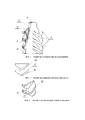
Фиг. 3 - общий вид спереди литого завихрителя.Fig. 3 is a general front view of the cast swirler.
Фиг. 4 - общий вид спереди литового вкладыша.Fig. 4 is a general front view of the cast insert.
Фиг. 5 - общий вид в изометрии литого вкладыша.Fig. 5 is a general isometric view of a cast insert.
Насадок дренчерный центробежный, функционирующий от водопроводной сети с рабочим давлением от 0,05 МПа, выполнен в виде пустотелого корпуса 1, который имеет входную нижнюю часть 2 с наружной присоединительной резьбой, имеет шестигранник 3, выполненный на средней части корпуса, имеет внутри корпуса выходную часть, выполненную в виде диффузора 4, при этом внутри корпуса входная нижняя часть выполнена в виде конфузора 5, в котором концентрично относительно оси корпуса расположены литой зивихритель 6 с размещенным в нем литым вкладышем 7, над завихрителем в корпусе выполнена камера 8, выход из камеры выполнен через горловину 9 определенной формы, которая характеризуется отношением высоты горловины к ее диаметру, приблизительно равным 1:5, горловина плавно сопряжена с диффузором, литой завихритель выполнен в виде пустотелой литой втулки, у которой на внешней нижней цилиндрической части 10 выполнена левая трапецеидальная четырехзаходная резьба 11, нижняя цилиндрическая часть литого завихрителя плавно переходит в верхнюю сферическую часть 12, которая сопрягается с верхней цилиндрической частью 13, внутри в нижней цилиндрической части литого завихрителя выполнена цилиндрическая полость, переходящая в средней части литого завихрителя в полость 14, выполненную в виде усеченного конуса, верхняя часть этой конусоидальной полости посредством небольшого диффузора 15 сообщена с камерой, в цилиндрической полости литого завихрителя установлен литой вкладыш, выполненный в виде центральной двухзаходной для потока ОТВ направляющей детали с правым направлением, при этом каждый ход направляющей детали выполнен в виде нижней наклонной плоскости 16, переходящей в горизонтальную ступень 17, которая переходит в верхнюю наклонную плоскость 18.The centrifugal deluge nozzle, operating from a water supply network with a working pressure of 0.05 MPa, is made in the form of a
Работает насадок дренчерный центробежный следующим образом.Works nozzle deluge centrifugal as follows.
При активации насадка дренчерного центробежного в процессе тушения пожара, ОТВ из трубопровода хозяйственно-питьевого назначения под давлением поступает в конфузор 5, далее поток ОТВ разделяется на периферийный поток, который закручиваясь по четырем каналам, образованным в пространстве между витками левой трапецеидальной четырехзаходной резьбы 10 и литым корпусом 1, поступает в камеру 8, туда же направляется центральный поток, который, проходя через нижнюю цилиндрическую часть 10 литого завихрителя 6, распадается посредством литого вкладыша 7 на два слегка закрученные вправо потока, которые попадают в полость, образованную усеченным конусом 14, далее оба потока под давлением через небольшой диффузор 15 завихрителя попадают в камеру. Из камеры периферийный и центральный потоки, вырываясь через горловину 9, проходя диффузор 4, разряжаются и дробятся, отрываются от корпуса и распыляются по защищаемой площади.When the nozzle of the deluge centrifugal nozzle is activated in the process of extinguishing a fire, the FTV from the pipeline for domestic and drinking purposes enters the
Claims (2)
Publications (1)
| Publication Number | Publication Date |
|---|---|
| RU2775503C1 true RU2775503C1 (en) | 2022-07-04 |
Family
ID=
Citations (4)
| Publication number | Priority date | Publication date | Assignee | Title |
|---|---|---|---|---|
| RU30275U1 (en) * | 2001-07-03 | 2003-06-27 | Закрытое акционерное общество Производственное объединение "Спецавтоматика" | Centrifugal atomizer |
| RU2297865C1 (en) * | 2005-08-03 | 2007-04-27 | ЗАО "ПО "Спецавтоматика" | Irrigator |
| US8833676B2 (en) * | 2008-07-18 | 2014-09-16 | Tie fu Han | Spraying device |
| CN207203271U (en) * | 2017-07-13 | 2018-04-10 | 沈阳二一三电子科技有限公司 | A kind of fire-fighting nozzle |
Patent Citations (4)
| Publication number | Priority date | Publication date | Assignee | Title |
|---|---|---|---|---|
| RU30275U1 (en) * | 2001-07-03 | 2003-06-27 | Закрытое акционерное общество Производственное объединение "Спецавтоматика" | Centrifugal atomizer |
| RU2297865C1 (en) * | 2005-08-03 | 2007-04-27 | ЗАО "ПО "Спецавтоматика" | Irrigator |
| US8833676B2 (en) * | 2008-07-18 | 2014-09-16 | Tie fu Han | Spraying device |
| CN207203271U (en) * | 2017-07-13 | 2018-04-10 | 沈阳二一三电子科技有限公司 | A kind of fire-fighting nozzle |
Similar Documents
| Publication | Publication Date | Title |
|---|---|---|
| RU2427402C1 (en) | Kochetov's sprayer | |
| RU2428235C1 (en) | Kochetov's vortex sprayer | |
| RU2557505C1 (en) | Centrifugal swirl atomiser of kochstar type | |
| RU2478409C1 (en) | Method of modular fire extinguishing | |
| RU2564281C1 (en) | Kochetov's atomiser to spray fluids | |
| RU2554331C1 (en) | Kochetov's centrifugal vortex burner | |
| RU2416444C1 (en) | Fluid sprayer | |
| RU2647104C2 (en) | Finely divided liquid sprayer | |
| RU2646675C2 (en) | Finely divided liquid sprayer | |
| RU2479333C1 (en) | Vortex foam generator of kochetov | |
| RU2775503C1 (en) | Centrifugal drencher nozzle | |
| RU2265467C1 (en) | Fire extinguisher | |
| RU2616857C1 (en) | Vortex nozzle | |
| RU2536396C1 (en) | Centifugal swirl atomiser of kochstar type | |
| RU2513174C1 (en) | Foam generator of vortex type | |
| RU2264833C1 (en) | Liquid sprayer and fire-extinguisher | |
| RU2577653C1 (en) | Kochetov centrifugal vortex burner | |
| EP3398659A1 (en) | Method of producing a fire extinguishant and spray duct for the implementation thereof | |
| RU2474447C1 (en) | Plant of modular fire suppression | |
| RU2456041C1 (en) | Sprayer | |
| RU2479332C1 (en) | Foam generator of vortex type | |
| RU2551733C1 (en) | Kochetov's fluid fine sprayer | |
| RU2622793C1 (en) | Kochetov's pneumatic dispenser | |
| CN203400440U (en) | Double-phase-flow fire sprinkler | |
| RU2655601C1 (en) | Pneumatic fluid sprayer |