RU2768766C1 - Steam turbine plant of the npp with an additional steam turbine and with a system for the safe use of hydrogen - Google Patents
Steam turbine plant of the npp with an additional steam turbine and with a system for the safe use of hydrogen Download PDFInfo
- Publication number
- RU2768766C1 RU2768766C1 RU2021112670A RU2021112670A RU2768766C1 RU 2768766 C1 RU2768766 C1 RU 2768766C1 RU 2021112670 A RU2021112670 A RU 2021112670A RU 2021112670 A RU2021112670 A RU 2021112670A RU 2768766 C1 RU2768766 C1 RU 2768766C1
- Authority
- RU
- Russia
- Prior art keywords
- hydrogen
- steam
- steam turbine
- npp
- oxygen
- Prior art date
Links
Images
Classifications
-
- G—PHYSICS
- G21—NUCLEAR PHYSICS; NUCLEAR ENGINEERING
- G21D—NUCLEAR POWER PLANT
- G21D1/00—Details of nuclear power plant
-
- Y—GENERAL TAGGING OF NEW TECHNOLOGICAL DEVELOPMENTS; GENERAL TAGGING OF CROSS-SECTIONAL TECHNOLOGIES SPANNING OVER SEVERAL SECTIONS OF THE IPC; TECHNICAL SUBJECTS COVERED BY FORMER USPC CROSS-REFERENCE ART COLLECTIONS [XRACs] AND DIGESTS
- Y02—TECHNOLOGIES OR APPLICATIONS FOR MITIGATION OR ADAPTATION AGAINST CLIMATE CHANGE
- Y02E—REDUCTION OF GREENHOUSE GAS [GHG] EMISSIONS, RELATED TO ENERGY GENERATION, TRANSMISSION OR DISTRIBUTION
- Y02E30/00—Energy generation of nuclear origin
Abstract
Description
Изобретение относится к области атомной энергетики и предназначено для использования на атомных электрических станциях (АЭС) работающие на влажном паре.The invention relates to the field of nuclear energy and is intended for use in nuclear power plants (NPP) operating on wet steam.
Известна парогазовая установка, содержащая подключенную к парогенератору паровую турбину насыщенного пара, между цилиндрами которой установлены сепаратор и паровой промежуточный пароперегреватель. Параллельно последнему включен газовый промежуточный пароперегреватель, сообщенный по греющей среде с выхлопным трактом газовой турбины. Газовая часть установки включает также компрессор, камеру нагрева и газовый подогреватель питательной воды паровой турбины, включенный в выхлопной тракт газовой турбины последовательно за пароперегревателем и соединенный с входом компрессора, т.е. газовая часть установки замкнута. Газовый подогреватель включен по питательной воде параллельно регенеративному подогревателю паровой турбины (остальные регенеративные подогреватели на чертеже не изображены). Установка снабжена системой получения и хранения водорода и кислорода, подключенной к камере нагрева, которая в свою очередь соединена с паровой турбиной (авт. свид. СССР на изобретение №1163681, МПК F01K 23/10, опубл. 15.12.1985 г.). Парогазовая установка предназначена для использования во время пиков электрической нагрузки в энергосистеме. Это осуществляется за счет того, что теплота от сжигания водорода с кислородом в камере нагрева подводится к рабочему телу газовой турбины, повышая его температуру и, тем самым, достигается большая выработка мощности. При этом нагрев рабочего тела осуществляется через разделяющую теплообменную поверхность. Отработавшее рабочее тело в газовой турбине отдает оставшуюся теплоту пару паротурбинной установки при промежуточном перегреве, вытесняя, тем самым, весь пар, предназначенный для осуществления промежуточного перегрева и, который, срабатывает в паровой турбине, повышая мощность паротурбинной установки.Known steam-gas plant containing connected to the steam turbine saturated steam, between the cylinders of which are installed separator and steam reheater. Parallel to the latter, a gas intermediate superheater is connected through the heating medium to the exhaust path of the gas turbine. The gas part of the installation also includes a compressor, a heating chamber, and a gas turbine feed water heater included in the gas turbine exhaust tract in series behind the superheater and connected to the compressor inlet, i.e. the gas part of the installation is closed. The gas heater is connected to the feed water in parallel with the regenerative heater of the steam turbine (other regenerative heaters are not shown in the drawing). The plant is equipped with a system for the production and storage of hydrogen and oxygen, connected to a heating chamber, which in turn is connected to a steam turbine (USSR inventor's certificate for the invention No. 1163681, IPC F01K 23/10, publ. 15.12.1985). The combined cycle plant is intended for use during peaks in the electrical load in the power system. This is due to the fact that the heat from the combustion of hydrogen with oxygen in the heating chamber is supplied to the working fluid of the gas turbine, increasing its temperature and, thereby, achieving a large power output. In this case, the heating of the working fluid is carried out through the separating heat exchange surface. The spent working fluid in the gas turbine gives off the remaining heat to the steam of the steam turbine plant during reheating, thereby displacing all the steam intended for reheating and which is triggered in the steam turbine, increasing the power of the steam turbine plant.
Недостатком известной парогазовой установки является образование непрореагировавшего водорода после сжигания в среде кислорода в потоке рабочего тела газотурбинной установки, что при соединении с непрореагировавшим кислородом приведет к образованию гремучей смеси. Также недостатком является наличие громоздкой теплопередающей поверхности, а также необходимость использования принудительного внешнего охлаждения камеры нагрева, где происходит образование высокотемпературного пара при окислении водорода кислородом специальной охлаждающей водой, что связано со значительным количеством отводимой теплоты, необходимой для изменения ее фазового состояния и сопряжено с образованием солевых отложений в тракте охлаждения, что со временем становится причиной неработоспособного состояния паро-водородного нагревателя. Все это снижает безопасность и эффективность использования водорода в цикле парогазовой установки.A disadvantage of the known steam-gas plant is the formation of unreacted hydrogen after combustion in an oxygen environment in the working fluid flow of the gas turbine plant, which, when combined with unreacted oxygen, will lead to the formation of an explosive mixture. Another disadvantage is the presence of a bulky heat transfer surface, as well as the need to use forced external cooling of the heating chamber, where high-temperature steam is formed during the oxidation of hydrogen with oxygen by special cooling water, which is associated with a significant amount of heat removed necessary to change its phase state and is associated with the formation of salt deposits in the cooling path, which over time becomes the cause of the inoperable state of the steam-hydrogen heater. All this reduces the safety and efficiency of using hydrogen in the cycle of a combined cycle plant.
Известна принципиальная схема двухконтурной АЭС с паро-водородным перегревом пара на параллельно подключенной к основной (сателлитной) турбоустановке (в статье Малышенко С.П., Назарова О.В., Сарумов Ю.А. Некоторые термодинамические и технико-экономические аспекты применения водорода как энергоносителя в энергетике // Атомно-водородная энергетика и технология. - М.: Энергоатомиздат. - 1986. - Вып. 7. - С. 116-117). Схема предназначена для достижения маневренности энергоблока АЭС. На сателлитную турбоустановку подается часть основного пара путем его разделения перед цилиндром высокого давления основной турбины АЭС. При входе в сателлитную турбоустановку осуществляется паро-водородный перегрев пара. При всех нагрузках тепловая мощность реактора и расход пара поддерживаются постоянными, так что открытие дроссельных клапанов, установленных на линии подачи пара в основную и сателлитную турбины приводит к изменению расхода пара через турбины, а значит, к изменению общей мощности турбоагрегатов. Увеличение расхода пара через сателлитную турбину при одновременном снижении его через основную турбину сопровождается ростом общей мощности энергоустановки, благодаря чему становится возможным плавное регулирование мощности и покрытие графика электрической нагрузки. Таким образом, достигается регулирование мощности энергоблока АЭС.A schematic diagram of a double-circuit NPP with steam-hydrogen superheating of steam on a parallel connected to the main (satellite) turbine plant is known (in the article Malyshenko S.P., Nazarova O.V., Sarumov Yu.A. Some thermodynamic and technical and economic aspects of the use of hydrogen as energy carrier in the energy sector // Atomic Hydrogen Energy and Technology. - M.: Energoatomizdat. - 1986. -
Недостатком известной принципиальной схемы является образование непрореагировавшего водорода после сжигания в среде кислорода в потоке рабочего тела сателлитной паровой турбины, что при соединении с непрореагировавшим кислородом приведет к образованию гремучей смеси. Также недостатком является менее эффективное использование теплоты высокотемпературных продуктов сгорания водорода в кислороде вследствие применения принудительного наружного охлаждения камеры сгорания, что связано со значительным количеством отводимой теплоты, необходимой для изменения фазового состояния охлаждающей воды, что снижает эффективность использования подведенной теплоты водорода. Также недостатком является образование солевых отложений в тракте внешнего охлаждения камеры сгорания охлаждающей водой, что со временем становится причиной неработоспособного состояния паро-водородного перегревателя. Таким образом, это снижает безопасность и эффективность повышения мощности энергоблока АЭС.A disadvantage of the known concept is the formation of unreacted hydrogen after combustion in an oxygen environment in the working fluid flow of a satellite steam turbine, which, when combined with unreacted oxygen, will lead to the formation of an explosive mixture. Also, the disadvantage is the less efficient use of the heat of high-temperature combustion products of hydrogen in oxygen due to the use of forced external cooling of the combustion chamber, which is associated with a significant amount of heat removed necessary to change the phase state of the cooling water, which reduces the efficiency of using the supplied heat of hydrogen. Also, the disadvantage is the formation of salt deposits in the path of external cooling of the combustion chamber with cooling water, which over time becomes the cause of the inoperable state of the steam-hydrogen superheater. Thus, it reduces the safety and efficiency of increasing the power of the nuclear power unit.
Известна турбинная установка АЭС (авт. свид. СССР на изобретение №936734, МПК G21D 1/00, опубл. 07.09.1983 г.), содержащая паровую турбину с цилиндром высокого давления (ЦВД) и цилиндром низкого давления (ЦНД), сепаратор, промежуточный перегреватель, систему для получения водорода и кислорода, включающую электролизную установку для получения водорода и водородные ресиверы, паро-водородный перегреватель, регенеративный подогреватель, установленный на трубопроводе питательной воды, водородный водонагреватель, задвижки и обратный клапан. При этом выход ЦВД через сепаратор и промежуточный перегреватель соединен с входом ЦНД, регенеративный подогреватель установлен на трубопроводе питательной воды и соединен с отбором пара от ЦВД и сепаратора, водородный пароперегреватель соединен с системой для получения водорода и кислорода, паро-водородный водонагреватель подключен по питательной воде через задвижку параллельно регенеративному подогревателю и к системе для получения водорода и кислорода, паро-водородный перегреватель подключен через задвижки параллельно промежуточному перегревателю.Known turbine plant NPP (ed. USSR certificate for invention No. 936734, IPC G21D 1/00, publ. 09/07/1983), containing a steam turbine with a high pressure cylinder (HPC) and a low pressure cylinder (LPC), a separator, an intermediate superheater, a system for producing hydrogen and oxygen, including an electrolysis plant for producing hydrogen and hydrogen receivers, a steam-hydrogen superheater, a regenerative heater installed on the feed water pipeline, a hydrogen water heater, valves and a check valve. At the same time, the outlet of the HPC through a separator and an intermediate superheater is connected to the inlet of the LPC, the regenerative heater is installed on the feed water pipeline and connected to the steam extraction from the HPC and the separator, the hydrogen superheater is connected to the system for producing hydrogen and oxygen, the steam-hydrogen water heater is connected via feed water through a valve in parallel with the regenerative heater and to the system for producing hydrogen and oxygen, the steam-hydrogen superheater is connected through valves in parallel with the reheater.
Турбинная установка позволяет увеличить мощность энергоблока АЭС в пиковые часы электрической нагрузки в энергосистеме. Это достигается за счет того, что промежуточный перегрев основного пара осуществляют в паро-водородном перегревателе, куда подается для сжигания водород. Вытесненный пар, предназначенный для осуществления промежуточного перегрева, срабатывает в основной турбине, повышая ее мощность.Turbine installation allows to increase the capacity of the NPP power unit during peak hours of electrical load in the power system. This is achieved due to the fact that the intermediate overheating of the main steam is carried out in a steam-hydrogen superheater, where hydrogen is supplied for combustion. Displaced steam, intended for reheating, works in the main turbine, increasing its power.
Недостатком известной турбинной установки является образование непрореагировавшего водорода после сжигания в среде кислорода в потоке рабочего тела паро-водородного перегревателя, что при соединении с непрореагировавшим кислородом приведет к образованию гремучей смеси. Также недостатком является наличие громоздкой теплопередающей поверхности, а также необходимость использования принудительного внешнего охлаждения водород-кислородной камеры сгорания, установленной внутри водородного пароперегревателя, где происходит образование высокотемпературного пара при окислении водорода кислородом специальной охлаждающей водой, что связано со значительным количеством отводимой теплоты, необходимой для изменения ее фазового состояния и сопряжено с образованием солевых отложений в тракте охлаждения, что со временем становится причиной неработоспособного состояния паро-водородного нагревателя. Все это снижает безопасность и эффективность использования водорода.A disadvantage of the known turbine plant is the formation of unreacted hydrogen after combustion in an oxygen environment in the flow of the working fluid of a steam-hydrogen superheater, which, when combined with unreacted oxygen, will lead to the formation of an explosive mixture. Also, the disadvantage is the presence of a bulky heat transfer surface, as well as the need to use forced external cooling of the hydrogen-oxygen combustion chamber installed inside the hydrogen superheater, where high-temperature steam is formed when hydrogen is oxidized by oxygen with special cooling water, which is associated with a significant amount of heat removed, which is necessary to change its phase state and is associated with the formation of salt deposits in the cooling path, which over time becomes the cause of the inoperable state of the steam-hydrogen heater. All this reduces the safety and efficiency of hydrogen use.
Известна гибридная атомная электростанция (патент РФ на изобретение №2537386, МПК G21D 5/14, G21D 5/16, опубл. 10.01.2015), содержащая ядерный реактор на тепловых нейтронах, реакторный парогенератор и паротурбинную установку, работающую на генератор, дополнительный ядерный реактор в качестве источника пароперегрева, подключенного к пароперегревателю по его греющей стороне. Вход пароперегревателя по нагреваемой стороне подключен к выходу парогенератора, а выход подключен к входу паротурбинной установки.Known hybrid nuclear power plant (RF patent for invention No. 2537386, IPC G21D 5/14, G21D 5/16, publ. 01/10/2015), containing a thermal neutron nuclear reactor, a reactor steam generator and a steam turbine plant powered by a generator, an additional nuclear reactor as a superheat source connected to the superheater on its heating side. The inlet of the superheater on the heated side is connected to the outlet of the steam generator, and the outlet is connected to the inlet of the steam turbine plant.
Гибридная АЭС предназначена для повышения эффективной мощности АЭС.A hybrid nuclear power plant is designed to increase the effective power of a nuclear power plant.
Недостатком известной гибридной АЭС является повышенная радиационная опасность в связи с применением дополнительного ядерного реактора с целью перегрева пара из парогенераторов. Это снижает безопасность использования гибридной АЭС.A disadvantage of the well-known hybrid nuclear power plant is the increased radiation hazard due to the use of an additional nuclear reactor to overheat steam from steam generators. This reduces the safety of using a hybrid nuclear power plant.
Известен способ работы энергоблока АЭС с водородной надстройкой и высокотемпературными электролизерами (патент РФ на изобретение №2682723, МПК G21D 7/00, опубл. 21.03.2019 г), включающий турбину с электрогенератором и подключенным к ней конденсатором, цех химводоочистки, бак-хранилище воды, а также подключенные к электрогенератору, по крайней мере, один пусковой электролизер, по крайней мере, один высокотемпературный электролизер, по крайней мере, два компрессора (один для водорода и второй для кислорода и выполнены с 2-3 ступенями сжатия и после каждой ступени установлен охладитель), конденсатный насос, двухрежимный водород-кислородный парогенератор (ДВКП). При этом ДВКП связан посредством двух паропроводов с турбиной и двух водопроводов, один из которых связан с цехом химводоочистки, другой - с тепловой схемой АЭС через бак-хранилище, конденсатный насос и конденсатор. При этом пусковой электролизер связан с баком-хранилищем воды и/или с цехом химводоочистки, а также подключен посредством газопроводов водорода и кислорода к ДВКП. Высокотемпературный электролизер связан посредством паропровода с ДВКП и посредством газопроводов водорода и кислорода с ДВКП, а также через компрессоры водорода и кислорода с хранилищем водорода и кислорода, которое также подключено газопроводами водорода и кислорода к ДВКП.A known method of operating a nuclear power plant with a hydrogen superstructure and high-temperature electrolyzers (RF patent for invention No. 2682723, IPC G21D 7/00, publ. 03/21/2019), including a turbine with an electric generator and a condenser connected to it, a chemical water treatment plant, a water storage tank , as well as connected to the electric generator, at least one starting electrolyzer, at least one high-temperature electrolyzer, at least two compressors (one for hydrogen and the second for oxygen and are made with 2-3 compression stages and after each stage cooler), condensate pump, dual-mode hydrogen-oxygen steam generator (DVKP). At the same time, the DVKP is connected by means of two steam pipelines to the turbine and two water pipelines, one of which is connected to the chemical water treatment plant, the other - to the thermal circuit of the NPP through a storage tank, a condensate pump and a condenser. At the same time, the starting electrolyzer is connected to a water storage tank and/or to a chemical water treatment plant, and is also connected to the DVKP via hydrogen and oxygen gas pipelines. The high-temperature electrolyzer is connected via a steam pipeline to the DVKP and through hydrogen and oxygen gas pipelines to the DVKP, as well as through hydrogen and oxygen compressors to a hydrogen and oxygen storage, which is also connected to the DVKP by hydrogen and oxygen gas pipelines.
АЭС с водородной надстройкой предназначена для повышения эффективности работы АЭС за счет снижения расхода электроэнергии на электролиз, повышение количества производимого водорода и кислорода, дополнительного повышения количества вырабатываемой электроэнергии в периоды максимума электрической нагрузки.A nuclear power plant with a hydrogen superstructure is designed to increase the efficiency of the NPP by reducing the consumption of electricity for electrolysis, increasing the amount of hydrogen and oxygen produced, and additionally increasing the amount of electricity generated during periods of maximum electrical load.
Недостатком известной схемы является образование непрореагировавшего водорода после сжигания в среде кислорода в потоке рабочего тела, что при соединении с непрореагировавшим кислородом приведет к образованию гремучей смеси. Также недостатком является необходимость использования принудительного внешнего охлаждения ДВКП, что связано со значительным количеством отводимой теплоты, необходимой для изменения ее фазового состояния и сопряжено с образованием солевых отложений в тракте охлаждения, что со временем становится причиной неработоспособного состояния паро-водородного нагревателя. Все это снижает безопасность и эффективность использования водорода.The disadvantage of the known scheme is the formation of unreacted hydrogen after combustion in an oxygen environment in the flow of the working fluid, which, when combined with unreacted oxygen, will lead to the formation of an explosive mixture. Also, a disadvantage is the need to use forced external cooling of the DVKP, which is associated with a significant amount of heat removed, which is necessary to change its phase state and is associated with the formation of salt deposits in the cooling path, which over time becomes the reason for the inoperable state of the steam-hydrogen heater. All this reduces the safety and efficiency of hydrogen use.
Известна парогазовая установка на базе АЭС (патент РФ на изобретение №2553725, МПК F01K 23/00, F24H 7/00, опубл. 20.06.2015), содержащая паровую турбину с цилиндрами высокого и низкого давления, соединенными между собой паропроводом с последовательно включенными в него сепаратором и двухступенчатым промежуточным паропаровым перегревателем, подогреватель высокого давления, газотурбинную установку, газопаровой подогреватель, подключенный по греющей стороне к тракту отработавших газов газовой турбины, а по нагреваемой - к паропроводу между цилиндрами паровой турбины параллельно второй ступени паропарового перегревателя, газоводяной подогреватель, подключенный по греющей стороне к тракту отработавших газов газовой турбины после газопарового подогревателя, а по нагреваемой - к трубопроводу питательной воды парового цикла и установленный параллельно подогревателю высокого давления, сателлитную турбину, дожигающее устройство, паровую электролизерную, хранилище кислорода, хранилище водорода, компрематор кислорода, компрематор водорода, водород-кислородный пароенератор.A combined-cycle plant based on nuclear power plants is known (RF patent for invention No. 2553725, IPC F01K 23/00,
Парогазовая установка предназначена для повышения коэффициента использования установленной мощности (КИУМ) энергоблока АЭС и всего энергокомплекса в целом за счет более глубокой утилизации уходящих газов ГТУ и предусмотрения резервной системы утилизации тепла ГТУ при выделении для реакторной установки строго базового режима и при одновременном расширении регулировочного диапазона всей энергоустановки, а также повышение эксплуатационной гибкости и маневренности парогазовой установки на базе АЭС и ГТУ с глубокой и вариативной утилизацией отработавших газов ГТУ.The combined cycle plant is designed to increase the installed capacity utilization factor (ICUF) of the NPP power unit and the entire power complex as a whole due to a deeper utilization of the gas turbine exhaust gases and the provision of a backup heat recovery system for the gas turbine when a strictly basic mode is allocated to the reactor plant and at the same time expanding the control range of the entire power plant , as well as increasing the operational flexibility and maneuverability of a combined cycle plant based on nuclear power plants and gas turbines with deep and variable utilization of exhaust gases from gas turbines.
Недостатком известной парогазовой установки на базе АЭС является содержание некоторой минимальной доли непрореагировавшего водорода и кислорода в паре после системы контроля и дожигания перед подачей в сателлитную турбину. Это требует применение дополнительной системы удаления непрореагировавшего водорода из потока рабочего тела, иначе это приведет к образованию гремучей смеси в конденсаторе как сателлитной турбины, так и в конденсаторе, либо деаэраторе основной турбины. Также недостатком является необходимость использования принудительного внешнего охлаждения водород-кислородной камеры сгорания, что связано со значительным количеством отводимой теплоты, необходимой для изменения ее фазового состояния и сопряжено с образованием солевых отложений в тракте охлаждения, что со временем становится причиной ее неработоспособного состояния. Все это снижает безопасность и эффективность использования водорода.A disadvantage of the known steam-gas plant based on nuclear power plants is the content of a certain minimum proportion of unreacted hydrogen and oxygen in the steam after the control and afterburning system before being fed into the satellite turbine. This requires the use of an additional system for removing unreacted hydrogen from the flow of the working fluid, otherwise it will lead to the formation of an explosive mixture in the condenser of both the satellite turbine and in the condenser or deaerator of the main turbine. Another disadvantage is the need to use forced external cooling of the hydrogen-oxygen combustion chamber, which is associated with a significant amount of heat removed necessary to change its phase state and is associated with the formation of salt deposits in the cooling path, which over time becomes the cause of its inoperable state. All this reduces the safety and efficiency of hydrogen use.
Известен способ и принципиальная схема повышения маневренности и безопасности АЭС на основе теплового и химического аккумулирования (патент РФ на изобретение №2640409, МПК G21D 1/00, опубл. 09.01.2018 г), содержащая основную паротурбинную установку (ПТУ), парогенератор (ПГ), устройство парораспределения, причем устройство парораспределения соединено с входом в основную ПТУ и ПГ посредством паропроводов, систему регенерации, электролизную установку для получения водорода и кислорода, водородные и кислородные ресиверы, водород-кислородный парогенератор, дополнительную ПТУ, бак горячей воды (БГВ), бак холодной воды (БХВ), поверхностный теплообменник.A known method and schematic diagram of increasing the maneuverability and safety of nuclear power plants based on thermal and chemical storage (RF patent for the invention No. 2640409, IPC G21D 1/00, publ. 01/09/2018), containing the main steam turbine plant (STU), steam generator (SG) , steam distribution device, moreover, the steam distribution device is connected to the entrance to the main STP and SG through steam pipelines, a regeneration system, an electrolysis plant for producing hydrogen and oxygen, hydrogen and oxygen receivers, a hydrogen-oxygen steam generator, an additional STP, a hot water tank (HWT), a tank cold water (CW), surface heat exchanger.
Сущность изобретения заключается в обеспечении надежного повышения маневренности и безопасности двухконтурной АЭС на основе теплового и химического аккумулирования внепиковой электроэнергии в виде водородного топлива и горячей воды, которые могут использоваться для выработки пиковой электроэнергии и обеспечения резервного электроснабжения собственных нужд АЭС с использованием энергии остаточного тепловыделения реактора при полном обесточивании.The essence of the invention is to ensure a reliable increase in the maneuverability and safety of a double-circuit NPP based on thermal and chemical storage of off-peak electricity in the form of hydrogen fuel and hot water, which can be used to generate peak electricity and provide backup power supply for the NPP's own needs using the energy of residual heat from the reactor at full de-energization.
Недостатком известного способа является образование непрореагировавшего водорода после сжигания в среде кислорода в потоке рабочего тела пи подаче в дополнительную паровую турбину, что при соединении с непрореагировавшим кислородом приведет к образованию гремучей смеси. Также недостатком является коррозионный износ рабочих лопаток паровой турбины из-за непрореагировавшего кислорода в условиях повышенной температуры свежего пара в результате его перегрева. Также недостатком является значительные затраты тепла из-за фазового изменения подаваемой воды на охлаждение при сжигании водорода с кислородом. Все это снижает безопасность, эффективность использования водорода и рабочий ресурс рабочих лопаток дополнительной паровой турбины.The disadvantage of this method is the formation of unreacted hydrogen after combustion in an oxygen environment in the flow of the working fluid and supply to an additional steam turbine, which, when combined with unreacted oxygen, will lead to the formation of an explosive mixture. Another disadvantage is the corrosive wear of the working blades of a steam turbine due to unreacted oxygen at an elevated temperature of fresh steam as a result of its overheating. Also, a disadvantage is the significant heat costs due to the phase change of the supplied water for cooling during the combustion of hydrogen with oxygen. All this reduces the safety, efficiency of hydrogen use and the operating life of the working blades of the additional steam turbine.
Известен способ повышения мощности двухконтурной АЭС за счет комбинирования с водородным циклом (патент РФ на изобретение №2707182, МПК G21D 5/16, опубл. 25.11.2019 г), при этом принципиальная схема содержит водород-кислородную камеру сгорания, тракт охлаждения продуктов сгорания, подогреватели высокого давления питательной воды, питательный насос.There is a known method for increasing the power of a bypass nuclear power plant by combining it with a hydrogen cycle (RF patent for invention No. 2707182, IPC G21D 5/16, publ. 11/25/2019), while the circuit diagram contains a hydrogen-oxygen combustion chamber, a combustion products cooling path, high pressure feed water heaters, feed pump.
Сущность изобретения заключается в повышении эффективности использования водородного топлива для повышения мощности и КПД АЭС за счет повышения параметров острого пара перед паровой турбиной и увеличенного расхода рабочего тела через ПГ и турбину вследствие дополнительного подогрева питательной воды после подогревателей высокого давления теплотой продуктов сгорания водорода в кислороде выше номинальной температуры, но не выше температуры кипения при данном давлении перед подачей в ПГ.The essence of the invention lies in increasing the efficiency of using hydrogen fuel to increase the power and efficiency of nuclear power plants by increasing the parameters of live steam before the steam turbine and the increased flow of the working fluid through the steam generator and the turbine due to additional heating of the feed water after the high-pressure heaters with the heat of the combustion products of hydrogen in oxygen above the nominal temperature, but not higher than the boiling point at a given pressure before being fed into the steam generator.
Недостатком известного способа является образование непрореагировавшего водорода после сжигания в среде кислорода в потоке рабочего тела при смешении высокотемпературных продуктов сгорания водорода в кислороде с питательной водой и со свежим паром, что при соединении с непрореагировавшим кислородом приведет к образованию гремучей смеси по тракту движения рабочего тела паротурбинной установки АЭС. Также недостатком является коррозионный износ рабочих лопаток паровой турбины из-за непрореагировавшего кислорода в условиях повышенной температуры свежего пара в результате его перегрева. Это снижает безопасность использования водорода и рабочий ресурс рабочих лопаток паровой турбины АЭС.The disadvantage of this method is the formation of unreacted hydrogen after combustion in an oxygen environment in the flow of the working fluid when high-temperature combustion products of hydrogen in oxygen are mixed with feed water and fresh steam, which, when combined with unreacted oxygen, will lead to the formation of an explosive mixture along the path of the working fluid of a steam turbine plant NUCLEAR PLANT. Another disadvantage is the corrosive wear of the working blades of a steam turbine due to unreacted oxygen at an elevated temperature of fresh steam as a result of its overheating. This reduces the safety of hydrogen use and the operating life of the working blades of the NPP steam turbine.
Известен способ водородного подогрева питательной воды на АЭС (патент РФ на изобретение №2709783, МПК G21D 5/00, F22B 1/26, F02C 3/30, F01K 3/18) содержащей водород-кислородную камеру сгорания, тракт охлаждения продуктов сгорания, подогреватели высокого давления питательной воды, питательный насос, компрессор, бак-аккумулятор, дополнительную паровую турбину.A known method of hydrogen heating of feed water at nuclear power plants (RF patent for invention No. 2709783,
Сущность изобретения заключается в повышении эффективности и надежности использования водородного топлива для повышения мощности АЭС за счет увеличения расхода рабочего тела через ПГ вследствие дополнительного подогрева питательной воды после подогревателей высокого давления выше номинальной температуры за счет тепла продуктов сгорания водорода в кислороде, но не выше температуры кипения при данном давлении перед подачей в ПГ.The essence of the invention lies in increasing the efficiency and reliability of using hydrogen fuel to increase the power of nuclear power plants by increasing the flow rate of the working fluid through the SG due to the additional heating of feed water after high-pressure heaters above the nominal temperature due to the heat of the combustion products of hydrogen in oxygen, but not higher than the boiling point at given pressure before being fed into the steam generator.
Недостатком известного изобретения является образование непрореагировавшего водорода после сжигания в среде кислорода в потоке рабочего тела при подаче в дополнительную паровую турбину, что при соединении с непрореагировавшим кислородом приведет к образованию гремучей смеси. Вместе с этим недостатком является коррозионный износ рабочих лопаток дополнительной паровой турбины из-за непрореагировавшего кислорода в условиях повышенной температуры свежего пара в результате его перегрева. Это снижает безопасность использования водорода и рабочий ресурс рабочих лопаток дополнительной паровой турбины.The disadvantage of the known invention is the formation of unreacted hydrogen after combustion in an oxygen environment in the flow of the working fluid when fed into an additional steam turbine, which, when combined with unreacted oxygen, will lead to the formation of an explosive mixture. Along with this disadvantage is the corrosive wear of the working blades of the additional steam turbine due to unreacted oxygen at an elevated temperature of fresh steam as a result of its overheating. This reduces the safety of using hydrogen and the operating life of the working blades of the additional steam turbine.
Известен способ повышения маневренности АЭС (патент РФ на изобретение №2529508, МПК G21D 1/00, опубл. 27.09.2014), включающий паровую турбину с цилиндрами высокого и низкого давления, устройство парораспределения, сепаратор, промежуточный перегреватель, систему для получения водорода и кислорода, включающую электролизную установку для получения водорода и кислорода с водородными и кислородными ресиверами.A known method for increasing the maneuverability of a nuclear power plant (RF patent for the invention No. 2529508,
Сущность изобретения заключается в обеспечении надежного и безопасного повышения маневренности и экономичности двухконтурной АЭС посредством работы ПГУ и водородного комплекса, оборудование которых выведено за территорию площадки станции.The essence of the invention is to ensure a reliable and safe increase in the maneuverability and efficiency of a double-circuit nuclear power plant through the operation of a CCGT and a hydrogen complex, the equipment of which is removed from the territory of the plant site.
Недостатком известного изобретения является образование непрореагировавшего водорода после сжигания в среде кислорода в потоке рабочего тела при подаче в дополнительную паровую турбину, что при соединении с непрореагировавшим кислородом приведет к образованию гремучей смеси. Также недостатком является коррозионный износ рабочих лопаток дополнительной паровой турбины из-за непрореагировавшего кислорода в условиях повышенной температуры свежего пара в результате его перегрева. Также недостатком является значительные затраты тепла из-за фазового изменения подаваемой воды на охлаждение водород-кислородной камеры сгорания. Все это снижает безопасность, эффективность использования водорода и рабочий ресурс рабочих лопаток дополнительной паровой турбины.The disadvantage of the known invention is the formation of unreacted hydrogen after combustion in an oxygen environment in the flow of the working fluid when fed into an additional steam turbine, which, when combined with unreacted oxygen, will lead to the formation of an explosive mixture. Also, the disadvantage is the corrosive wear of the working blades of the additional steam turbine due to unreacted oxygen at an elevated temperature of fresh steam as a result of its overheating. Also, a disadvantage is the significant heat costs due to the phase change of the supplied water for cooling the hydrogen-oxygen combustion chamber. All this reduces the safety, efficiency of hydrogen use and the operating life of the working blades of the additional steam turbine.
Известен способ расхолаживания водоохлаждаемого реактора при полном обесточивании АЭС (патент РФ на изобретение №2499307, МПК G21D 3/08, опубл. 20.11.2013 г), содержащий паропроизводящую установку с ядерным энергетическим водоохлаждаемым реактором, пароэнергетическую турбогенераторную установку, дополнительную паровую турбину, систему производства и хранения водорода и кислорода, систему расхолаживания паропроизводящей установки.A known method of cooling down a water-cooled reactor with a complete blackout of a nuclear power plant (RF patent for the invention No. 2499307,
Способ предназначен для расхолаживания водоохлаждаемого реактора в штатном режиме при полном обесточивании АЭС, без использования аварийных систем расхолаживания реактора, за счет использования энергии остаточных тепловыделений в активной зоне, энергии сжигания водородного топлива и дополнительной турбины, эффективно используемой для повышения маневренности энергоблока АЭС в эксплуатационных режимах.The method is designed to cool down a water-cooled reactor in the normal mode with a complete blackout of the NPP, without using emergency reactor cooldown systems, by using the energy of residual heat in the core, the energy of burning hydrogen fuel and an additional turbine, which is effectively used to increase the maneuverability of the NPP power unit in operating modes.
Недостатком известного способа является образование непрореагировавшего водорода после сжигания в среде кислорода в потоке рабочего тела дополнительной паровой турбины, что при соединении с непрореагировавшим кислородом приведет к образованию гремучей смеси. Также недостатком является коррозионный износ рабочих лопаток дополнительной паровой турбины из-за непрореагировавшего кислорода в условиях повышенной температуры свежего пара в результате его перегрева. Также недостатком является значительные затраты тепла из-за фазового изменения подаваемой воды на охлаждение водород-кислородной камеры сгорания, что сопряжено с образованием солевых отложений в тракте охлаждения, что со временем становится причиной ее неработоспособного состояния. Все это снижает безопасность, эффективность использования водорода и рабочий ресурс рабочих лопаток дополнительной паровой турбины.The disadvantage of this method is the formation of unreacted hydrogen after combustion in an oxygen environment in the working fluid flow of an additional steam turbine, which, when combined with unreacted oxygen, will lead to the formation of an explosive mixture. Also, the disadvantage is the corrosive wear of the working blades of the additional steam turbine due to unreacted oxygen at an elevated temperature of fresh steam as a result of its overheating. Also, a disadvantage is the significant heat costs due to the phase change of the supplied water for cooling the hydrogen-oxygen combustion chamber, which is associated with the formation of salt deposits in the cooling path, which over time becomes the cause of its inoperable state. All this reduces the safety, efficiency of hydrogen use and the operating life of the working blades of the additional steam turbine.
Известна установка для обеспечения маневренности АЭС (патент на полезную модель РФ №70312, МПК F01K 13/02, H02J 9/04, G21D 3/08, опубл. 20.01.2008 г) содержащая ядерный реактор, парогенератор, паровую турбину, соединенную с электрогенератором, и через конденсатор и конденсатный насос с системой регенеративных подогревателей низкого давления, связанной последовательно установленными деаэратором, питательным насосом парогенератора, подогревателями высокого давления, соединенными с парогенератором, причем подогреватели низкого и высокого давления через конденсатор связаны с паровой турбиной, выходной вал которой соединен с электрогенератором, который связан с реактором для получения кислорода и водорода, за которым установлены емкости для накопления и хранения кислорода и водорода, соединенные с расположенными в технологической последовательности камерой сгорания, паровой турбиной сверхкритических параметров, вторыми конденсатором и конденсатным насосом, связанным через регулирующий клапан с подогревателями низкого давления, деаэратором, питательным насосом камеры сгорания, подогревателями высокого давления, связанными с камерой сгорания, при этом конденсатный насос соединен с резервуаром для воды, связанный с помощью насосов с реактором для получения кислорода и водорода с одной стороны и с камерой сгорания с другой, а подогреватели низкого и высокого давления соединены через второй конденсатор с паровой турбиной сверхкритических параметров, соединенной со вторым электрогенератором.A known installation for ensuring the maneuverability of nuclear power plants (utility model patent of the Russian Federation No. 70312, IPC F01K 13/02, H02J 9/04, G21D 3/08, publ. 01/20/2008) containing a nuclear reactor, a steam generator, a steam turbine connected to an electric generator , and through a condenser and a condensate pump with a system of low pressure regenerative heaters connected in series with a deaerator, a steam generator feed pump, high pressure heaters connected to the steam generator, and the low and high pressure heaters are connected through the condenser to a steam turbine, the output shaft of which is connected to an electric generator , which is connected to the reactor for producing oxygen and hydrogen, after which there are tanks for accumulating and storing oxygen and hydrogen, connected to a combustion chamber located in the technological sequence, a supercritical steam turbine, a second condenser and a condensate pump connected through a control valve n with low-pressure heaters, deaerator, combustion chamber feed pump, high-pressure heaters connected to the combustion chamber, while the condensate pump is connected to a water tank, connected by means of pumps to a reactor for producing oxygen and hydrogen on one side and to the combustion chamber on the other hand, the low and high pressure heaters are connected through the second condenser to a supercritical steam turbine connected to the second electric generator.
Недостатком известной полезной модели является образование непрореагировавшего водорода после сжигания в среде кислорода в потоке рабочего тела паровой турбины сверхкритических параметров, что при соединении с непрореагировавшим кислородом приведет к образованию гремучей смеси. Также недостатком является коррозионный износ рабочих лопаток паровой турбины из-за непрореагировавшего кислорода в условиях повышенной температуры свежего пара в результате его перегрева. Также недостатком является необходимость использования принудительного внешнего охлаждения водород-кислородной камеры сгорания, что связано со значительным количеством отводимой теплоты, необходимой для изменения ее фазового состояния и сопряжено с образованием солевых отложений в тракте охлаждения, что со временем становится причиной ее неработоспособного состояния. Все это снижает безопасность, эффективность использования водорода и рабочий ресурс рабочих лопаток дополнительной паровой турбины.A disadvantage of the well-known utility model is the formation of unreacted hydrogen after combustion in an oxygen environment in the flow of the working fluid of a steam turbine of supercritical parameters, which, when combined with unreacted oxygen, will lead to the formation of an explosive mixture. Another disadvantage is the corrosive wear of the working blades of a steam turbine due to unreacted oxygen at an elevated temperature of fresh steam as a result of its overheating. Another disadvantage is the need to use forced external cooling of the hydrogen-oxygen combustion chamber, which is associated with a significant amount of heat removed necessary to change its phase state and is associated with the formation of salt deposits in the cooling path, which over time becomes the cause of its inoperable state. All this reduces the safety, efficiency of hydrogen use and the operating life of the working blades of the additional steam turbine.
Известна турбинная установка атомной электростанции (варианты) (патент РФ на изобретение №2459293, МПК G21D 1/00, опубл. 20.08.2012 г). Турбинная установка АЭС содержит паровую турбину с цилиндром высокого давления и цилиндром низкого давления, сепаратор, промежуточный перегреватель, систему для получения водорода и кислорода, включающую электролизную установку для получения водорода и кислорода с водородными и кислородными ресиверами, пароводородные перегреватели, устройство парораспределения. При этом вход цилиндра высокого давления соединен трубопроводом с устройством парораспределения, пароводородные перегреватели соединены с системой для получения водорода и кислорода. По первому варианту введена сателлитная вытесненного пара, которая подключена к устройству парораспределения, а выход цилиндра высокого давления через сепаратор, пароводородный перегреватель и промежуточный перегреватель соединен с входом цилиндра низкого давления. По второму варианту введена сателлитная паротурбинная установка с трубопроводом вытесненного пара и пароводородным перегревателем вытесненного пара, соединенным с системой для получения водорода и кислорода и с устройством парораспределения перед цилиндром высокого давления, выход пароводородного перегревателя вытесненного пара соединен с сателлитной паротурбинной установкой, а выход цилиндра высокого давления соединен с входом цилиндра низкого давления.A turbine plant of a nuclear power plant (options) is known (RF patent for the invention No. 2459293,
Турбинная установка предназначена для устранения переменного расхода рабочего тела через основную паровую турбину АЭС при повышении мощности энергоблока выше номинальной.The turbine plant is designed to eliminate the variable flow rate of the working fluid through the main steam turbine of the NPP when the power unit's power is increased above the nominal one.
Недостатком известного изобретения является образование непрореагировавшего водорода после сжигания в среде кислорода в потоке рабочего тела основной турбины АЭС и дополнительной паровой турбины, что при соединении с непрореагировавшим кислородом приведет к образованию гремучей смеси. Вместе с тем наличие непрореагировавшего кислорода будет способствовать коррозионному разрушению рабочих лопаток цилиндра низкого давления основной турбины АЭС и всех рабочих лопаток дополнительной турбины в условиях повышенной температуры пара в результате его перегрева. Также недостатком является необходимость использования принудительного внешнего охлаждения водород-кислородной камеры сгорания, что связано со значительным количеством отводимой теплоты, необходимой для изменения ее фазового состояния и сопряжено с образованием солевых отложений в тракте охлаждения, что со временем становится причиной ее неработоспособного состояния. Все это снижает безопасность, эффективность использования водорода и рабочий ресурс рабочих лопаток цилиндра низкого давления основной паровой турбины АЭС и всех рабочих лопаток дополнительной паровой турбины.A disadvantage of the known invention is the formation of unreacted hydrogen after combustion in an oxygen environment in the working fluid flow of the main turbine of the nuclear power plant and an additional steam turbine, which, when combined with unreacted oxygen, will lead to the formation of an explosive mixture. At the same time, the presence of unreacted oxygen will contribute to the corrosion destruction of the working blades of the low-pressure cylinder of the main NPP turbine and all the working blades of the additional turbine at elevated steam temperatures as a result of its overheating. Another disadvantage is the need to use forced external cooling of the hydrogen-oxygen combustion chamber, which is associated with a significant amount of heat removed necessary to change its phase state and is associated with the formation of salt deposits in the cooling path, which over time becomes the cause of its inoperable state. All this reduces the safety, efficiency of hydrogen use and the working life of the working blades of the low-pressure cylinder of the main steam turbine of the NPP and all the working blades of the additional steam turbine.
Наиболее близким аналогом является магнитная сепарация недоокисленного газообразного водорода из среды перегретого водяного пара под давлением с использованием магнитного поля соленоида после системы сжигания в паротурбинном цикле атомных теплоэнергетических установок (патент РФ на изобретение №2579849 С1, опубл. 10.04.2016 г). Магнитный сепаратор включает соленоид, рабочий канал для транспортировки очищаемого потока, при этом основной трубопровод круглого сечения имеет прямолинейное направление, во внутренней части которого в пристеночной области по всему периметру установлена селективная мембрана на основе сплава палладия с серебром на участке воздействия магнитного поля на очищаемый поток перегретого водяного пара под давлением от недоокисленного газообразного водорода после системы сжигания в цикле паротурбинной установки. С внешней стороны основного трубопровода предусмотрен сообщающийся с ним стравливающий трубопровод диффундирующего сквозь мембрану отсепарированного водорода с установленным на нем соответствующим выпускным клапаном, а также датчиком концентрации диффундирующего сквозь мембрану отсепарированного водорода.The closest analogue is the magnetic separation of underoxidized gaseous hydrogen from a medium of superheated water vapor under pressure using the magnetic field of the solenoid after the combustion system in the steam turbine cycle of nuclear thermal power plants (RF patent for the invention No. 2579849 C1, publ. 10.04.2016). The magnetic separator includes a solenoid, a working channel for transporting the stream being cleaned, while the main pipeline of circular cross section has a rectilinear direction, in the inner part of which, in the near-wall region around the entire perimeter, a selective membrane based on an alloy of palladium and silver is installed in the area where the magnetic field affects the superheated stream being cleaned pressurized water vapor from under-oxidized hydrogen gas after the combustion system in the steam turbine plant cycle. On the outer side of the main pipeline, a bleed pipeline of the separated hydrogen diffusing through the membrane is provided, which communicates with it, with a corresponding outlet valve installed on it, as well as a concentration sensor for the separated hydrogen diffusing through the membrane.
Изобретение предназначено для использования в паротурбинных установках АЭС с системой сжигания водорода с кислородом с содержанием непрореагировавшего водорода в рабочем теле под давлением после системы сжигания перед поступлением в турбину.The invention is intended for use in steam turbine plants of nuclear power plants with a hydrogen-oxygen combustion system containing unreacted hydrogen in the working fluid under pressure after the combustion system before entering the turbine.
Недостатком известного изобретения является невозможность полного удаления непрореагировавшего водорода, что приводит к сохранению опасности образования гремучей смеси водорода с кислородом, а также невозможность удаления непрореагировавшего кислорода, что приведет к коррозионному разрушению рабочих лопаток как основной турбины АЭС, так и дополнительной турбины в условиях повышения температуры пара в результате его перегрева. Все это снижает безопасность использования водорода и рабочий ресурс рабочих лопаток паровой турбины АЭС и дополнительной турбины.The disadvantage of the known invention is the impossibility of complete removal of unreacted hydrogen, which leads to the preservation of the danger of the formation of an explosive mixture of hydrogen and oxygen, as well as the impossibility of removing unreacted oxygen, which will lead to corrosion destruction of the working blades of both the main turbine of the nuclear power plant and the additional turbine under conditions of increasing steam temperature. as a result of overheating. All this reduces the safety of using hydrogen and the working life of the working blades of the NPP steam turbine and the additional turbine.
Задачей настоящего изобретения является повышение безопасности использования водорода в паротурбинной установке АЭС с использованием дополнительной турбины.The objective of the present invention is to improve the safety of using hydrogen in a nuclear power plant steam turbine plant using an additional turbine.
Техническим результатом, достигаемым при использовании настоящего изобретения, является практически полное удаление непрореагировавшего водорода при существенном снижении концентрации непрореагировавшего кислорода в рабочем теле паротурбинной установки АЭС и сохранение номинального рабочего ресурса рабочих лопаток основной турбины АЭС и дополнительной турбины.The technical result achieved by using the present invention is the almost complete removal of unreacted hydrogen with a significant decrease in the concentration of unreacted oxygen in the working fluid of the NPP steam turbine plant and the preservation of the nominal working life of the working blades of the main NPP turbine and additional turbine.
Указанный технический результат достигается тем, что паротурбинная установка АЭС с использованием дополнительной паровой турбины с системой сжигания водорода в кислороде с содержанием непрореагировавшего водорода и кислорода в паровой фазе рабочего тела под давлением содержит магнитный сепаратор, включающий соленоид, рабочий канал для транспортировки очищаемого потока пара от непрореагировавшего водорода при этом основной трубопровод круглого сечения и выполнен с возможностью прямолинейного направления, во внутренней части которого в пристеночной области по всему периметру установлена селективная мембрана на основе сплава палладия с серебром на участке воздействия магнитного поля на очищаемый поток водяного пара, согласно изобретения, после водород-кислородной камеры сгорания перед цилиндром высокого давления дополнительной турбины паротурбинной установки АЭС и после промежуточного пароперегревателя перед цилиндром низкого давления основной турбины паротурбинной установки АЭС установлены каталитические рекомбинаторы (дожигатели) непрореагировавшего водорода.This technical result is achieved by the fact that the NPP steam turbine plant using an additional steam turbine with a hydrogen-in-oxygen combustion system containing unreacted hydrogen and oxygen in the vapor phase of the working fluid under pressure contains a magnetic separator, including a solenoid, a working channel for transporting the cleaned steam stream from the unreacted hydrogen at the same time, the main pipeline is of circular cross section and is made with the possibility of a rectilinear direction, in the inner part of which, in the near-wall region around the entire perimeter, a selective membrane based on an alloy of palladium and silver is installed in the area where the magnetic field affects the stream of water vapor being cleaned, according to the invention, after hydrogen - oxygen combustion chamber before the high-pressure cylinder of the additional turbine of the NPP steam turbine plant and after the intermediate superheater before the low-pressure cylinder of the main turbine of the NPP steam turbine plant We are catalytic recombiners (afterburners) of unreacted hydrogen.
Повышение безопасности и эффективности использования водорода в паротурбинной установке АЭС при повышении ее мощности выше номинальной достигается за счет того, что в каталитических рекомбинаторах происходит дожигание непрореагировавшего водорода с кислородом, что существенно снижает его концентрацию в рабочем теле дополнительной и основной турбины паротурбинной установки АЭС при этом в устройстве магнитного сепаратора за счет воздействия неоднородного магнитного поля соленоида происходит дополнительное удаление оставшегося количества непрореагировавшего водорода за счет его сорбции в мембране из палладиевого сплава. Возможный оставшийся непрореагировавший кислород удаляется системой эжекторных насосов. Комбинирование каталитического дожигания и магнитного сепаратора позволяет практически полностью удалить непрореагировавший водород из рабочего тела дополнительной и основной турбины паротурбинной установки АЭС. При этом водород-кислородные камеры сгорания, установленные перед цилиндром высокого давления дополнительной турбины паротурбинной установки АЭС и перед пароперегревателем основной турбины паротурбинной установки АЭС выполнены из ультравысокотемпературного керамического материала без принудительного водяного охлаждения. Данные материалы способны длительно работать в окислительной среде при температурах до 2000°С. При этом температура плавления у керамики на основе борида гафния и циркония 3380 и 3250°С соответственно. Температура плавления у керамики на основе карбида гафния 3890°С. Имеют небольшую плотность и высокие прочностные свойства при повышенных температурах. Таким образом, данные материалы более надежны и долговечны в условиях термических напряжений при сжигании водорода в кислороде без использования внешнего водяного охлаждения по сравнению с жаропрочными сталями и сплавами, такими как, например, ХН35ВТ, 36Х18Н25С2, 13Х11Н2ВМФ, 12Х18Н10Т.An increase in the safety and efficiency of hydrogen use in the NPP steam turbine plant with an increase in its power above the nominal value is achieved due to the fact that in the catalytic recombiners, unreacted hydrogen is burned with oxygen, which significantly reduces its concentration in the working fluid of the additional and main turbine of the NPP steam turbine plant, while in In the device of a magnetic separator, due to the influence of a non-uniform magnetic field of the solenoid, the remaining amount of unreacted hydrogen is additionally removed due to its sorption in the palladium alloy membrane. Any remaining unreacted oxygen is removed by a system of ejector pumps. The combination of catalytic afterburning and a magnetic separator makes it possible to almost completely remove unreacted hydrogen from the working fluid of the auxiliary and main turbines of the NPP steam turbine plant. At the same time, the hydrogen-oxygen combustion chambers installed in front of the high-pressure cylinder of the additional turbine of the NPP steam turbine plant and in front of the superheater of the main turbine of the NPP steam turbine plant are made of ultra-high-temperature ceramic material without forced water cooling. These materials are able to work for a long time in an oxidizing environment at temperatures up to 2000°C. The melting temperature of ceramics based on hafnium and zirconium boride is 3380 and 3250°C, respectively. The melting temperature of ceramics based on hafnium carbide is 3890°C. They have low density and high strength properties at elevated temperatures. Thus, these materials are more reliable and durable under conditions of thermal stresses during the combustion of hydrogen in oxygen without the use of external water cooling in comparison with heat-resistant steels and alloys, such as, for example, KhN35VT, 36Kh18N25S2, 13Kh11N2VMF, 12Kh18N10T.
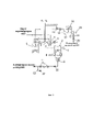
Изобретение иллюстрируется чертежом, где на фиг. 1 показана принципиальная схема ПТУ АЭС с дополнительной паровой турбиной и с системой безопасного использования водорода.The invention is illustrated in the drawing, where in Fig. 1 shows a schematic diagram of a NPP STU with an additional steam turbine and a system for the safe use of hydrogen.
Позиции на чертеже обозначают следующее: 1 - цилиндр высокого давления основной турбины паротурбинной установки АЭС; 2 - цилиндр низкого давления основной турбины паротурбинной установки АЭС; 3 - сепаратор основной турбины паротурбинной установки АЭС; 4 - водород-кислородная камера сгорания из ультравысокотемпературного материала основной турбины паротурбинной установки АЭС; 5 - промежуточный перегреватель основной турбины паротурбинной установки АЭС; 6 - каталитический рекомбинатор непрореагировавшего водорода основной турбины паротурбинной установки АЭС; 7 - электрический генератор основной турбины паротурбинной установки АЭС; 8 - магнитный сепаратор непрореагировавшего водорода основной турбины паротурбинной установки АЭС; 9 - конденсатор основной турбины паротурбинной установки АЭС; 10 - конденсатный насос основной турбины паротурбинной установки АЭС; 11 - подогреватели низкого давления основной турбины паротурбинной установки АЭС; 12 - рециркуляция добавленного рабочего тела при промперегреве пара основной турбины паротурбинной установки АЭС; 13 - водород-кислородная камера сгорания из ультравысокотемпературного материала дополнительной турбины паротурбинной установки АЭС; 14 - каталитический рекомбинатор непрореагировавшего водорода дополнительной турбины паротурбинной установки АЭС; 15 - цилиндр высокого давления дополнительной турбины паротурбинной установки АЭС; 16 - сепаратор дополнительной турбины паротурбинной установки АЭС; 17 - цилиндр низкого давления дополнительной турбины паротурбинной установки АЭС; 18 - электрический генератор дополнительной турбины паротурбинной установки АЭС; 19 - магнитный сепаратор непрореагировавшего водорода дополнительной турбины паротурбинной установки АЭС; 20 - конденсатор дополнительной турбины паротурбинной установки АЭС.The positions in the drawing indicate the following: 1 - high pressure cylinder of the main turbine of the NPP steam turbine plant; 2 - low pressure cylinder of the main turbine of the NPP steam turbine plant; 3 - separator of the main turbine of the NPP steam turbine plant; 4 - hydrogen-oxygen combustion chamber made of ultra-high-temperature material of the main turbine of the NPP steam turbine plant; 5 - intermediate superheater of the main turbine of the NPP steam turbine plant; 6 - catalytic recombiner of unreacted hydrogen of the main turbine of the NPP steam turbine plant; 7 - electric generator of the main turbine of the NPP steam turbine plant; 8 - magnetic separator of unreacted hydrogen of the main turbine of the NPP steam turbine plant; 9 - condenser of the main turbine of the NPP steam turbine plant; 10 - condensate pump of the main turbine of the NPP steam turbine plant; 11 - low pressure heaters of the main turbine of the NPP steam turbine plant; 12 - recirculation of the added working fluid during reheating of the steam of the main turbine of the NPP steam turbine plant; 13 - hydrogen-oxygen combustion chamber made of ultra-high-temperature material of an additional turbine of a steam turbine plant of a nuclear power plant; 14 - catalytic recombiner of unreacted hydrogen of the additional turbine of the NPP steam turbine plant; 15 - high-pressure cylinder of the additional turbine of the NPP steam turbine plant; 16 - separator of the additional turbine of the NPP steam turbine plant; 17 - low pressure cylinder of the additional turbine of the NPP steam turbine plant; 18 - electric generator of the additional turbine of the NPP steam turbine plant; 19 - magnetic separator of unreacted hydrogen of the additional turbine of the NPP steam turbine plant; 20 - condenser of the additional turbine of the NPP steam turbine plant.
Паротурбинная установка АЭС с дополнительной паровой турбиной и с системой безопасного использования водорода содержит основную паровую турбину с цилиндром высокого давления 1 и цилиндром низкого давления 2, сепаратор основной турбины паротурбинной установки АЭС 3, водород-кислородную камеру сгорания из ультравысокотемпературного материала основной турбины паротурбинной установки АЭС 4. промежуточный перегреватель основной турбины паротурбинной установки АЭС 5, каталитический рекомбинатор непрореагировавшего водорода основной турбины паротурбинной установки АЭС 6, электрический генератор основной турбины паротурбинной установки АЭС 7, магнитный сепаратор непрореагировавшего водорода основной турбины паротурбинной установки АЭС 8, конденсатор основной турбины паротурбинной установки АЭС 9, конденсатный насос основной турбины паротурбинной установки АЭС 10, подогреватели низкого давления основной турбины паротурбинной установки АЭС 11, рециркуляция добавленного рабочего тела при промперегреве пара основной турбины паротурбинной установки АЭС 12, водород-кислородная камера сгорания из ультравысокотемпературного материала дополнительной турбины паротурбинной установки АЭС 13, каталитический рекомбинатор непрореагировавшего водорода дополнительной турбины паротурбинной установки АЭС 14, цилиндр высокого давления 15 и цилиндр низкого давления 17 дополнительной турбины паротурбинной установки АЭС, сепаратор дополнительной турбины паротурбинной установки АЭС 16, электрический генератор дополнительной турбины паротурбинной установки АЭС 18, магнитный сепаратор непрореагировавшего водорода дополнительной турбины паротурбинной установки АЭС 19, конденсатор дополнительной турбины паротурбинной установки АЭС 20, систему для получения водорода и кислорода, включающую электролизную установку с водородными и кислородными ресиверами. При этом вход водород-кислородных камер сгорания 4 и 13 соединен с магистралями подачи водорода и кислорода из системы получения и хранения. Вход камеры сгорания 4 через сепаратор 3 соединен с выходом цилиндра высокого давления основной турбины паротурбинной установки АЭС. Выход камеры сгорания 4 через промежуточный перегреватель пара 5 и каталитический рекомбинатор 6 основной турбины паротурбинной установки АЭС соединен со входом в цилиндр низкого давления основной турбины паротурбинной установки АЭС 2. Выход цилиндра низкого давления основной турбины паротурбинной установки АЭС 2 соединен со входом в магнитный сепаратор 8, выход которого соединен со входом в конденсатор 9 основной турбины паротурбинной установки АЭС. Выход конденсатора основной турбины паротурбинной установки АЭС 9 соединен через конденсатный насос 10 с подогревателями низкого давления 11 и с системой регенерации. Рециркуляция 12 подмешанного пара, полученного при сжигании водорода в кислороде, к основному пару основной турбины паротурбинной установки АЭС при промперегреве в виде конденсата осуществляется после подогревателей низкого давления 11 с целью возврата в электролиз. Вход водород-кислородной камеры сгорания 13 соединен с трубопроводом подачи свежего пара из парогенераторов в количестве, равном вытесненному пару, предназначенного для промперегрева пара основной турбины паротурбинной установки АЭС. Выход водород-кислородной камеры сгорания 13 соединен с входом в каталитический рекомбинатор 14, выход которого соединен с входом в цилиндр высокого давления дополнительной турбины паротурбинной установки АЭС 15, а выход цилиндра высокого давления дополнительной турбины соединен через сепаратор 16 с входом в цилиндр низкого давления дополнительной турбины паротурбинной установки АЭС 17. Выход цилиндра низкого давления дополнительной турбины 17 соединен с входом в магнитный сепаратор 19, выход которого соединен с входом в конденсатор дополнительной турбины паротурбинной установки АЭС 20.The NPP steam turbine plant with an additional steam turbine and with a system for the safe use of hydrogen contains a main steam turbine with a high pressure cylinder 1 and a low pressure cylinder 2, a separator of the main turbine of the NPP steam turbine plant 3, a hydrogen-oxygen combustion chamber made of ultra-high-temperature material of the main turbine of the NPP steam turbine plant 4 reheater of the main turbine of the NPP 5 steam turbine plant, catalytic recombiner of unreacted hydrogen of the main turbine of the NPP 6 steam turbine plant, electric generator of the main turbine of the NPP 7 steam turbine plant, magnetic separator of unreacted hydrogen of the main turbine of the NPP 8 steam turbine plant, condenser of the main turbine of the NPP 9 steam turbine plant, condensate pump of the main turbine of the NPP 10 steam turbine plant, low-pressure heaters of the main turbine of the NPP 11 steam turbine plant, recirculation of the added working fluid during the promoter steam heating of the main turbine of the NPP 12 steam turbine plant, hydrogen-oxygen combustion chamber made of ultra-high-temperature material of the additional turbine of the NPP 13 steam turbine plant, catalytic recombiner of unreacted hydrogen of the additional turbine of the NPP 14 steam turbine plant, high pressure cylinder 15 and low pressure cylinder 17 of the additional turbine of the NPP steam turbine plant, separator of the additional turbine of the NPP 16 steam turbine plant, electric generator of the additional turbine of the NPP 18 steam turbine plant, magnetic separator of unreacted hydrogen of the additional turbine of the NPP 19 steam turbine plant, condenser of the additional turbine of the NPP 20 steam turbine plant, a system for producing hydrogen and oxygen, including an electrolysis plant with hydrogen and oxygen receivers. At the same time, the inlet of the hydrogen-
Паротурбинная установка АЭС с дополнительной паровой турбиной и с системой безопасного использования водорода включает подачу водорода и кислорода по подводящим магистралям в водород-кислородные камеры сгорания 4 и 13, выполненные из ультравысокотемпературного керамического материала без принудительного водяного охлаждения, соединенные с системой получения и хранения водорода и кислорода. За счет ступенчатого окисления водорода кислородом с образованием высокотемпературного пара и его смешения с паром основной турбины паротурбинной установки АЭС осуществляется промперегрев. При этом пар, предназначенный для промперегрева поступает в водород-кислородную камеру сгорания дополнительной турбины паротурбинной установки АЭС 13, где он перегревается. Ввиду сложности обеспечения условий для полного сжигания водорода, образуется непрореагировавший водород и кислород в паре дополнительной и основной турбины паротурбинной установки АЭС. С целью снижения концентрации непрореагировавшего водорода и недопущения образования гремучей смеси, перед цилиндром низкого давления основной турбины паротурбинной установки АЭС 2 и перед цилиндром высокого давления дополнительной турбины паротурбинной установки АЭС 15 установлены каталитические рекомбинаторы 6 и 14 соответственно, в которых происходит дожигание непрореагировавшего водорода в кислороде. Дополнительно после цилиндра низкого давления основной турбины паротурбинной установки АЭС 2 и после цилиндра низкого давления дополнительной турбины паротурбинной установки АЭС 17 установлены магнитные сепараторы непрореагировавшего водорода 8 и 19 соответственно, в котором под воздействием неоднородного магнитного поля соленоида происходит дополнительное удаление оставшегося количества непрореагировавшего водорода посредством контактной палладиевой мембраны. Возможный оставшийся непрореагировавший кислород удаляется системой эжекторных насосов. На основе выполненных расчетов автором заявки определена возможность практически полного удаления непрореагировавшего водорода из рабочего тела паротурбинного цикла АЭС с предотвращением образования гремучей смеси.The NPP steam turbine plant with an additional steam turbine and a system for the safe use of hydrogen includes the supply of hydrogen and oxygen through supply lines to hydrogen-
Паротурбинная установка АЭС с дополнительной паровой турбиной и с системой безопасного использования водорода работает следующим образом. В ночные провальные часы электрической нагрузки за счет процесса электролиза воды происходит аккумулирование невостребованной электроэнергии АЭС в виде водорода и кислорода, которые при помощи дожимных водородных и кислородных компрессорных агрегатов поступают в систему хранения на основе металлических емкостей. В пиковые часы электрических нагрузок водород и кислород отбираются из емкостей хранения и при помощи дожимных водородных и кислородных компрессорных агрегатов подаются по соответствующим подводящим магистралям в водород-кислородные камеры сгорания 4 и 13, выполненные из ультравысокотемпературного керамического материала. За счет водород-кислородной камеры сгорания 4 осуществляется промперегрев пара основной турбины паротурбинной установки АЭС за счет смешения с паром, полученного при сжигании водорода в кислороде, что приводит к возможности подачи вытесненного пара, предназначенного для промперегрева в водород-кислородную камеру сгорания 13 дополнительной турбины. В водород-кислородной камере сгорания 13 за счет высокотемпературного пара, полученного в результате ступенчатого окисления водорода кислородом и его смешения со свежим паром перед цилиндром высокого давления дополнительной турбины паротурбинной устанвоки АЭС 15, происходит его перегрев. В результате повышается температура пара при входе в дополнительную турбину, что способствует повышению вырабатываемой мощности выше номинальной электрогенератором 18. За счет применения ультравысокотемпературного керамического материала для водород-кислородных камер сгорания 4 и 13 отсутствует необходимость их принудительного водяного охлаждения, что исключает затраты тепла на фазовое превращение охлаждающей воды и повышает термодинамическую эффективность использования теплоты от сжигания водорода в паротурбинном цикле АЭС. Ввиду сложности обеспечения условий для полного сжигания водорода, образуется непрореагировавший водород и кислород в паре дополнительной и основной турбины паротурбинной установки АЭС. С целью снижения концентрации непрореагировавшего водорода и недопущения образования гремучей смеси перед цилиндром низкого давления основной турбины паротурбинной установки АЭС 2 и перед цилиндром высокого давления дополнительной турбины паротурбинной установки АЭС 15 установлены каталитические рекомбинаторы 6 и 14 соответственно, в которых происходит дожигание непрореагировавшего водорода в кислороде. Дополнительно после цилиндра низкого давления основной турбины паротурбинной установки АЭС 2 и после цилиндра низкого давления дополнительной турбины паротурбинной установки АЭС 17 установлены магнитные сепараторы непрореагировавшего водорода 8 и 19 соответственно, в котором под воздействием неоднородного магнитного поля соленоида происходит дополнительное удаление оставшегося количества непрореагировавшего водорода посредством контактной палладиевой мембраны. После того, как пар с содержанием некоторого количества непрореагировавшего водорода и кислорода отработал в цилиндре низкого давления и давление его снизилось, далее двигается в трубопроводе прямолинейного направления через область воздействия неоднородного магнитного поля соленоида, в виде обмотки токового провода в изоляции с внешней стороны трубопровода, находящейся внутри водяной рубашки охлаждения и подключенного к источнику электропитания. При этом на внутренней поверхности участка трубопровода по всему периметру нанесена палладиевая мембрана. Необходимая рабочая температура мембраны может быть обеспечена электронагревом. Вследствие того, что соленоид обмотан с внешней стороны трубопровода, то вектор магнитной индукции сонаправлен с направлением движения пара с содержанием непрореагировавшего водорода и кислорода. В этом случае возникающая сила Лоренца, действующая на электроны непрореагировавшего водорода, направлена перпендикулярно линиям магнитной индукции поля. У молекулярного водорода (диамагнетик) ввиду спаренности электронов отсутствует собственное внешнее магнитное поле. Под воздействием неоднородного внешнего магнитного поля в результате действия силы Лоренца искривляются сферические орбиты движения электронов, что создаем силу, стремящаяся переместить водород в область более слабого поля, т.е., в направлении к периферии внутреннего пространства трубопровода, где искривления орбит будут минимальными. У молекулярного кислорода (парамагнетик) ввиду наличия неспаренных электронов имеется собственное внешнее магнитное поле. Под воздействием неоднородного внешнего магнитного поля спины неспаренных электронов ориентируются в направлении поля и кислород втягивается в область более сильного поля, т.е., в направлении к центральной оси соленоида, совпадающей с центром трубопровода. Таким образом, это приводит к взаимному разделению водорода и кислорода в неоднородном магнитном поле. Возможный оставшийся непрореагировавший кислород удаляется системой эжекторных насосов. На основе выполненных расчетов автором заявки определена возможность практически полного удаления непрореагировавшего водорода из рабочего тела основной и дополнительной турбины паротурбинной установки АЭС с предотвращением образования гремучей смеси. Таким образом, комбинирование каталитических рекомбинаторов и магнитного сепаратора создает условия, при которых в конденсаторах основной и дополнительной турбин паротурбинной установки АЭС 9 и 20 соответственно не возникает образование гремучей смеси в виде неконденсирующихся газов - водорода и кислорода.The steam turbine plant of a nuclear power plant with an additional steam turbine and a system for the safe use of hydrogen operates as follows. During night failure hours of electrical load, due to the process of water electrolysis, unclaimed electricity from nuclear power plants is accumulated in the form of hydrogen and oxygen, which, using booster hydrogen and oxygen compressor units, enter the storage system based on metal containers. During peak hours of electrical loads, hydrogen and oxygen are taken from the storage tanks and, using booster hydrogen and oxygen compressor units, are fed through the corresponding supply lines to the hydrogen-
Отличительным признаком предложенной паротурбинной установки АЭС с дополнительной паровой турбиной и с системой безопасного использования водорода является практически полное удаление непрореагировавшего водорода при существенном снижении концентрации непрореагировавшего кислорода из паровой фазы рабочего тела основной и дополнительной турбины паротурбинной установки АЭС и сохранение номинального рабочего ресурса рабочих лопаток основной паровой турбины АЭС и дополнительной турбины.A distinctive feature of the proposed NPP steam turbine plant with an additional steam turbine and with a system for the safe use of hydrogen is the almost complete removal of unreacted hydrogen with a significant decrease in the concentration of unreacted oxygen from the vapor phase of the working fluid of the main and additional turbines of the NPP steam turbine plant and the preservation of the nominal working life of the working blades of the main steam turbine Nuclear power plant and additional turbine.
Claims (1)
Priority Applications (1)
| Application Number | Priority Date | Filing Date | Title |
|---|---|---|---|
| RU2021112670A RU2768766C1 (en) | 2021-04-29 | 2021-04-29 | Steam turbine plant of the npp with an additional steam turbine and with a system for the safe use of hydrogen |
Applications Claiming Priority (1)
| Application Number | Priority Date | Filing Date | Title |
|---|---|---|---|
| RU2021112670A RU2768766C1 (en) | 2021-04-29 | 2021-04-29 | Steam turbine plant of the npp with an additional steam turbine and with a system for the safe use of hydrogen |
Publications (1)
| Publication Number | Publication Date |
|---|---|
| RU2768766C1 true RU2768766C1 (en) | 2022-03-24 |
Family
ID=80819473
Family Applications (1)
| Application Number | Title | Priority Date | Filing Date |
|---|---|---|---|
| RU2021112670A RU2768766C1 (en) | 2021-04-29 | 2021-04-29 | Steam turbine plant of the npp with an additional steam turbine and with a system for the safe use of hydrogen |
Country Status (1)
| Country | Link |
|---|---|
| RU (1) | RU2768766C1 (en) |
Cited By (1)
| Publication number | Priority date | Publication date | Assignee | Title |
|---|---|---|---|---|
| RU2792761C1 (en) * | 2022-07-13 | 2023-03-23 | Федеральное государственное бюджетное учреждение "Национальный исследовательский центр "Курчатовский институт" | Nuclear energy process system and method for its operation |
Citations (6)
| Publication number | Priority date | Publication date | Assignee | Title |
|---|---|---|---|---|
| SU936734A1 (en) * | 1980-05-20 | 1983-09-07 | Саратовский политехнический институт | Nuclear power plant turbine unit |
| US20100043435A1 (en) * | 2008-08-19 | 2010-02-25 | Hinders Edward B | Methods for Enhancing Efficiency of Steam-Based Generating Systems |
| RU2459293C1 (en) * | 2011-06-08 | 2012-08-20 | Рашид Зарифович Аминов | Nuclear power station turbine plant (versions) |
| RU2537386C1 (en) * | 2013-06-20 | 2015-01-10 | Виктор Николаевич Иванюк | Hybrid nuclear power plant |
| US9006915B1 (en) * | 2012-07-06 | 2015-04-14 | Byung-Youl Choi | Mechanical energy storage system and generating method using the same |
| RU2579849C1 (en) * | 2015-02-25 | 2016-04-10 | Артем Николаевич Байрамов | Magnetic separation of non-oxidised hydrogen gas from medium of superheated steam under pressure using magnetic field of solenoid after combustion system in steam turbine cycle of nuclear heat and power plants |
-
2021
- 2021-04-29 RU RU2021112670A patent/RU2768766C1/en active
Patent Citations (6)
| Publication number | Priority date | Publication date | Assignee | Title |
|---|---|---|---|---|
| SU936734A1 (en) * | 1980-05-20 | 1983-09-07 | Саратовский политехнический институт | Nuclear power plant turbine unit |
| US20100043435A1 (en) * | 2008-08-19 | 2010-02-25 | Hinders Edward B | Methods for Enhancing Efficiency of Steam-Based Generating Systems |
| RU2459293C1 (en) * | 2011-06-08 | 2012-08-20 | Рашид Зарифович Аминов | Nuclear power station turbine plant (versions) |
| US9006915B1 (en) * | 2012-07-06 | 2015-04-14 | Byung-Youl Choi | Mechanical energy storage system and generating method using the same |
| RU2537386C1 (en) * | 2013-06-20 | 2015-01-10 | Виктор Николаевич Иванюк | Hybrid nuclear power plant |
| RU2579849C1 (en) * | 2015-02-25 | 2016-04-10 | Артем Николаевич Байрамов | Magnetic separation of non-oxidised hydrogen gas from medium of superheated steam under pressure using magnetic field of solenoid after combustion system in steam turbine cycle of nuclear heat and power plants |
Non-Patent Citations (5)
| Title |
|---|
| Aminov R. Z. Assessment of the Performance of a Nuclear-Hydrogen Power Generation System / R. Z. Aminov, A. N. Bairamov, M. V. Garievskii // Thermal Engineering. 2019. N 3. Vol.66. pp.196-209. Bairamov A.N. Evaluation of the operating resource of the most loaded rotor element of the additional steam turbine with steam-hydrogen overheat of the working fluid at a nuclear power station // Journal of Physics: Conference Series. 2017. Vol.891. 012252. P.1-9. Aminov R.Z., Bairamov A.N., Shatskova O. V. Assessment of the Efficiency of Hydrogen Cycles on the Basis of Off-Peak Electric Energy Produced at a Nuclear Power Station // Thermal Engineering. - 2009. - Т.56. N 11 - P. 940 - 945. * |
| Aminov R.Z., Bairamov A.N., Shatskova O. V. Assessment of the Efficiency of Hydrogen Cycles on the Basis of Off-Peak Electric Energy Produced at a Nuclear Power Station // Thermal Engineering. - 2009. - Т.56. N 11 - P. 940 - 945. * |
| Bairamov A.N. Evaluation of the operating resource of the most loaded rotor element of the additional steam turbine with steam-hydrogen overheat of the working fluid at a nuclear power station // Journal of Physics: Conference Series. 2017. Vol.891. 012252. P.1-9. * |
| C1. * |
| C1. Aminov R. Z. Assessment of the Performance of a Nuclear-Hydrogen Power Generation System / R. Z. Aminov, A. N. Bairamov, M. V. Garievskii // Thermal Engineering. 2019. N 3. Vol.66. pp.196-209. * |
Cited By (2)
| Publication number | Priority date | Publication date | Assignee | Title |
|---|---|---|---|---|
| RU2792761C1 (en) * | 2022-07-13 | 2023-03-23 | Федеральное государственное бюджетное учреждение "Национальный исследовательский центр "Курчатовский институт" | Nuclear energy process system and method for its operation |
| RU2805458C1 (en) * | 2022-11-23 | 2023-10-17 | Николай Геннадьевич Кириллов | Nuclear power unit for nuclear-powered ships |
Similar Documents
| Publication | Publication Date | Title |
|---|---|---|
| CN109184812B (en) | Nuclear energy coupling chemical energy power generation system and method based on two-loop boiler | |
| WO2011075923A1 (en) | High-temperature gas-cooled reactor steam generating system and method | |
| CA2679811A1 (en) | High efficiency feedwater heater | |
| RU70312U1 (en) | INSTALLATION FOR ENSURING MANEUVERABILITY OF ATOMIC ELECTRIC STATIONS | |
| CN108843414B (en) | Working method for coupling and decoupling nuclear energy and conventional energy with reheating power generation system | |
| RU2768766C1 (en) | Steam turbine plant of the npp with an additional steam turbine and with a system for the safe use of hydrogen | |
| RU2769511C1 (en) | Npp steam turbine plant with hydrogen safe use system | |
| CN114183742A (en) | Reheating steam extraction and heat storage combined denitration load reduction system | |
| RU2661231C1 (en) | Method of hydrogen steam overheating at npp | |
| RU2529508C1 (en) | Method of improvement of manoeuvrability of atomic power plants | |
| RU2604208C1 (en) | Method to increase npp cyclic load capability and safety | |
| WO2006126914A1 (en) | Nuclear power plant and a steam turbine | |
| RU2609894C1 (en) | Method for active removal of residual heat emission of reactors under conditions of nps blackout | |
| RU2459293C1 (en) | Nuclear power station turbine plant (versions) | |
| CN112303604A (en) | Economizer temperature governing system that unit start-up process denitration was put into | |
| RU2602649C2 (en) | Steam turbine npp | |
| RU2736603C1 (en) | System for safe use of hydrogen while increasing power of double-circuit npp above nominal | |
| Aminov et al. | Evaluation of the efficiency of combining wet-steam NPPs with a closed hydrogen cycle | |
| RU2709783C1 (en) | Method of hydrogen heating of feed water to npp | |
| RU2759559C1 (en) | Method for increasing safety and technical and economic efficiency of npp operation under uniform energy consumption based on hydrogen-heat storage | |
| RU2547828C1 (en) | Steam-gas unit of two-circuit nuclear power plant | |
| RU2489574C1 (en) | Steam and gas plant based on npp | |
| RU2707182C1 (en) | Method to increase power of double circuit npp by combining with hydrogen cycle | |
| RU2553725C1 (en) | Steam-gas unit based on nuclear power plant | |
| SU787695A1 (en) | Power plant |