RU2761503C1 - Electrohydraulic control system - Google Patents
Electrohydraulic control system Download PDFInfo
- Publication number
- RU2761503C1 RU2761503C1 RU2020142348A RU2020142348A RU2761503C1 RU 2761503 C1 RU2761503 C1 RU 2761503C1 RU 2020142348 A RU2020142348 A RU 2020142348A RU 2020142348 A RU2020142348 A RU 2020142348A RU 2761503 C1 RU2761503 C1 RU 2761503C1
- Authority
- RU
- Russia
- Prior art keywords
- hydraulic
- outlet
- inlet
- valve
- pump
- Prior art date
Links
- 238000010438 heat treatment Methods 0.000 claims abstract description 7
- 238000006073 displacement reaction Methods 0.000 claims description 5
- 239000000126 substance Substances 0.000 abstract 1
- 239000012530 fluid Substances 0.000 description 7
- 230000033228 biological regulation Effects 0.000 description 2
- 238000013461 design Methods 0.000 description 2
- 238000010586 diagram Methods 0.000 description 2
- 230000014759 maintenance of location Effects 0.000 description 2
- 238000000034 method Methods 0.000 description 2
- 238000013459 approach Methods 0.000 description 1
- 238000011010 flushing procedure Methods 0.000 description 1
- 230000005484 gravity Effects 0.000 description 1
- 230000003287 optical effect Effects 0.000 description 1
- 230000002028 premature Effects 0.000 description 1
- 238000005086 pumping Methods 0.000 description 1
- 238000012360 testing method Methods 0.000 description 1
- 238000012546 transfer Methods 0.000 description 1
Images
Classifications
-
- F—MECHANICAL ENGINEERING; LIGHTING; HEATING; WEAPONS; BLASTING
- F15—FLUID-PRESSURE ACTUATORS; HYDRAULICS OR PNEUMATICS IN GENERAL
- F15B—SYSTEMS ACTING BY MEANS OF FLUIDS IN GENERAL; FLUID-PRESSURE ACTUATORS, e.g. SERVOMOTORS; DETAILS OF FLUID-PRESSURE SYSTEMS, NOT OTHERWISE PROVIDED FOR
- F15B9/00—Servomotors with follow-up action, e.g. obtained by feed-back control, i.e. in which the position of the actuated member conforms with that of the controlling member
- F15B9/02—Servomotors with follow-up action, e.g. obtained by feed-back control, i.e. in which the position of the actuated member conforms with that of the controlling member with servomotors of the reciprocatable or oscillatable type
- F15B9/03—Servomotors with follow-up action, e.g. obtained by feed-back control, i.e. in which the position of the actuated member conforms with that of the controlling member with servomotors of the reciprocatable or oscillatable type with electrical control means
Landscapes
- Engineering & Computer Science (AREA)
- Fluid-Pressure Circuits (AREA)
- Physics & Mathematics (AREA)
- Fluid Mechanics (AREA)
- Mechanical Engineering (AREA)
- General Engineering & Computer Science (AREA)
Abstract
Description
Изобретение относится к электрогидравлическим системам управления и предназначено для подъема и опускания полезной инерционной нагрузки (радиолокационных модулей, оптических систем) из походного положения в рабочее и обратно.The invention relates to electro-hydraulic control systems and is intended for raising and lowering the inertial payload (radar modules, optical systems) from the stowed position to the working position and vice versa.
Известна электрогидравлическая система управления (патент РФ №2271479 от 10.03.2006 г., МПК F15B 9/04). Система содержит исполнительный гидродвигатель, регулируемый насос и золотниковый механизм с регулируемой производимостью дросселирующих окон для регулирования положения выходного вала гидродвигателя. В качестве управляющего элемента золотника использован электромеханический элемент, а для обеспечения качества регулирования использован датчик положения золотника и датчик положения вала гидродвигателя.Known electrohydraulic control system (RF patent No. 2271479 dated 03/10/2006, IPC F15B 9/04). The system contains an executive hydraulic motor, a variable pump and a spool mechanism with variable capacity of throttling ports to regulate the position of the output shaft of the hydraulic motor. An electromechanical element is used as a spool control element, and a spool position sensor and a hydraulic motor shaft position sensor are used to ensure the quality of regulation.
Недостатками данной системы являются повышенная сложность конструкции и, как следствие, недостаточная надежность.The disadvantages of this system are the increased complexity of the design and, as a consequence, insufficient reliability.
Указанные недостатки частично устранены в электрогидравлической системе управления (патент РФ №2347950 от 27.02.2009 г., МПК F15B 9/03), взятой нами в качестве прототипа.These disadvantages are partially eliminated in the electrohydraulic control system (RF patent No. 2347950 dated February 27, 2009, IPC F15B 9/03), taken by us as a prototype.
Электрогидравлическая система управления содержит гидробак, гидроцилиндры, блок управления, блок задания скорости, трехпозиционный гидрораспределитель с электромагнитами, насос постоянной производительности, гидрозамок и переливной клапан, при этом выход блока задания скорости соединен с входом блока управления, первый и второй выходы блока управления соединены с электромагнитами трехпозиционного гидрораспределителя, вход насоса постоянной производительности соединен с первым выходом гидробака, первый выход трехпозиционного гидрораспределителя соединен с первым входом гидроцилиндра и первым входом гидрозамка, а третий вход гидрозамка соединен со вторым входом гидроцилиндра.The electrohydraulic control system contains a hydraulic tank, hydraulic cylinders, a control unit, a speed setting unit, a three-position hydraulic valve with electromagnets, a constant displacement pump, a hydraulic lock and an overflow valve, while the output of the speed setting unit is connected to the input of the control unit, the first and second outputs of the control unit are connected to electromagnets a three-position hydraulic valve, the inlet of the constant-flow pump is connected to the first outlet of the hydraulic tank, the first outlet of the three-position hydraulic valve is connected to the first inlet of the hydraulic cylinder and the first inlet of the hydraulic lock, and the third inlet of the hydraulic lock is connected to the second inlet of the hydraulic cylinder.
Электрогидравлическая система управления работает следующим образом. Находясь в исходном положении, релейный гидрораспределитель создает гидролинию с небольшим гидравлическим сопротивлением от насоса до гидробака. При появлении электрического сигнала от блока задания скорости блок управления, вырабатывает по заданному алгоритму сигнал управления дросселирующим электрогидрораспределителем. Регулирование скорости перемещения нагрузки обеспечивается за счет изменения гидравлического сопротивления дросселирующего электрогидрорасперделителя.The electro-hydraulic control system works as follows. When in the initial position, the relay valve creates a hydraulic line with a small hydraulic resistance from the pump to the hydraulic tank. When an electrical signal appears from the speed setting unit, the control unit generates, according to a given algorithm, a control signal for the throttling electrohydraulic valve. Regulation of the speed of movement of the load is provided by changing the hydraulic resistance of the throttling electrohydraulic distributor.
Недостатком указанной системы является невозможность управления гидроцилиндрами при отсутствии электропитания насосной установки, а также при возможном выходе из строя электромагнита трехпозиционного гидрораспределителя, что указывает на ограниченные функциональные возможности, сложность конструкции и сказывается на надежности.The disadvantage of this system is the impossibility of controlling the hydraulic cylinders in the absence of power supply to the pumping unit, as well as in the event of a possible failure of the electromagnet of the three-position hydraulic valve, which indicates limited functionality, the complexity of the design and affects the reliability.
Задачей предполагаемого изобретения является расширение функциональных возможностей и эксплуатационной надежности системы.The objective of the proposed invention is to enhance the functionality and operational reliability of the system.
Поставленная задача решается электрогидравлической системой управления, включающей гидробак, гидроцилиндры, блок управления, блок задания скорости, трехпозиционный гидрораспределитель с электромагнитами, насос постоянной производительности, гидрозамок и переливной клапан, при этом выход блока задания скорости соединен с входом блока управления, первый и второй выходы блока управления соединены с электромагнитами трехпозиционного гидрораспределителя, вход насоса постоянной производительности соединен с первым выходом гидробака, первый выход трехпозиционного гидрораспределителя соединен с первым входом гидроцилиндра и первым входом гидрозамка, а третий вход гидрозамка соединен со вторым входом гидроцилиндра, при этом, новым является то, что в нее введены насос ручной, фильтр и обратный клапан, в трехпозиционный гидрораспределитель введен ручной привод, а в блок управления введена плата обогрева, соединенная с выходом блока задания скорости, также вход насоса ручного соединен со вторым выходом гидробака, при этом выход насоса ручного и выход насоса постоянной производительности соединены с входом переливного клапана и входом фильтра, выход фильтра соединен с напорным входом трехпозиционного гидрораспределителя, вход обратного клапана соединен со сливным выходом трехпозиционного гидрораспределителя и выходом переливного клапана, а его выход - с входом насоса постоянной призводительности и первым выходом гидробака, также второй выход трехпозиционного гидрораспределителя соединен с первым и вторым входами гидрозамка.The task is solved by an electro-hydraulic control system, which includes a hydraulic tank, hydraulic cylinders, a control unit, a speed setting unit, a three-position hydraulic valve with electromagnets, a constant-flow pump, a hydraulic lock and an overflow valve, while the output of the speed setting unit is connected to the input of the control unit, the first and second outputs of the unit controls are connected to the electromagnets of the three-position hydraulic valve, the input of the constant-flow pump is connected to the first outlet of the hydraulic tank, the first output of the three-position hydraulic valve is connected to the first input of the hydraulic cylinder and the first input of the hydraulic lock, and the third input of the hydraulic lock is connected to the second input of the hydraulic cylinder, while the new is that in a manual pump, a filter and a check valve are introduced, a manual drive is introduced into the three-position hydraulic valve, and a heating board is introduced into the control unit, connected to the output of the speed setting unit, and the input of the manual pump is connected to the second hydraulic tank stroke, while the output of the manual pump and the output of the constant-flow pump are connected to the inlet of the overflow valve and the inlet of the filter, the outlet of the filter is connected to the pressure inlet of the three-position hydraulic valve, the inlet of the check valve is connected to the drain outlet of the three-position hydraulic distributor and the outlet of the overflow valve, and its outlet is connected to the input of the constant capacity pump and the first output of the hydraulic tank, and the second output of the three-position hydraulic valve is connected to the first and second inputs of the hydraulic lock.
Плата обогрева соединена с блоком задания скорости посредством электролинии.The heating board is connected to the speed setting unit by means of a power line.
Вход насоса ручного соединен со вторым выходом гидробака посредствам гидролинии.The inlet of the manual pump is connected to the second outlet of the hydraulic tank by means of a hydraulic line.
Выход насоса ручного и выход насоса постоянной производительности соединены с входом переливного клапана и входом фильтра посредствам отдельных гидролиний.The outlet of the manual pump and the outlet of the constant displacement pump are connected to the inlet of the overflow valve and the inlet of the filter by means of separate hydraulic lines.
Выход фильтра соединен с напорным входом трехпозиционного гидрораспределителя посредствам гидролинии.The filter outlet is connected to the pressure inlet of the three-position hydraulic valve by means of a hydraulic line.
Вход обратного клапана соединен со сливным выходом трехпозиционного гидрораспределителя и выходом переливного клапана посредствам гидролинии.The inlet of the check valve is connected to the drain outlet of the three-position directional valve and the outlet of the overflow valve by means of a hydraulic line.
Выход обратного клапана соединен с входом насоса постоянной производительности и первым выходом гидробака посредствам гидролинии.The outlet of the check valve is connected to the inlet of the constant displacement pump and the first outlet of the hydraulic tank by means of a hydraulic line.
Второй выход трехпозиционного гидрораспределителя соединен с первым (управляющим) и вторым входами гидрозамка посредствам гидролиний.The second outlet of the three-position hydraulic valve is connected to the first (control) and second inputs of the hydraulic lock by means of hydraulic lines.
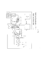
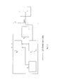
Предложенное техническое решение поясняется графическими изображениями, где на фиг. 1 представлена схема электрогидравлической системы управления, а на фиг. 2 представлена структурная схема блока управления гидросистемой.The proposed technical solution is illustrated by graphic images, where Fig. 1 shows a diagram of an electro-hydraulic control system, and FIG. 2 shows a block diagram of the hydraulic system control unit.
1 - блок задания скорости (БЗС);1 - speed setting block (BZS);
2 - блок управления (БУ);2 - control unit (BU);
3 - насос ручной (HP);3 - hand pump (HP);
4 - насос постоянной производительности (НПП);4 - constant displacement pump (NPP);
5 - фильтр;5 - filter;
6 - обратный клапан (ОК);6 - check valve (OK);
7 - трехпозиционный гидрораспределитель;7 - three-position hydraulic valve;
8 - гидроцилиндр;8 - hydraulic cylinder;
9 - гидробак;9 - hydraulic tank;
10 - переливной клапан (ПК);10 - overflow valve (PC);
11 - гидрозамок;11 - hydraulic lock;
12 - плата обогрева (ПО);12 - heating board (software);
13 - функциональный преобразователь (ФП);13 - functional converter (FP);
14 - блок питания (БП);14 - power supply unit (PSU);
15 - каскады включения.15 - cascades of inclusion.
Система содержит БЗС 1, гидроцилиндр 8, гидробак 9, ПК 10, гидрозамок 11, НПП 4 с ОК 6, трехпозиционный гидрораспределитель 7 с фильтром 5, HP 3, БУ 2 с ПО 12, вход которой соединен электролинией с выходом БЗС 1, при этом первый и второй выходы БУ 2 соединены электролиниями с трехпозиционным гидрораспределителем 7, выход НУ 4 соединен гидролиниями с входом фильтра 5 и входом ПК 10, выход HP 3 гидролиниями соединен с входом фильтра 5 и входом ПК 10, выход фильтра 5 гидролинией соединен с напорным входом трехпозиционного гидрораспределителя 7, вход НПП 4 гидролиниями соединен с первым выходом гидробака 9 и выходом ОК 6, вход HP 3 гидролинией соединен со вторым выходом гидробака 9, первый выход трехпозиционного гидрораспределителя 7 гидролиниями соединен с первым входом гидроцилиндра 8 и первым (управляющим) входом гидрозамка 11, выход ПК 10 гидролиниями соединен со входом OK 6 и сливным выходом трехпозиционного гидрораспределителя 7, второй выход которого гидролиниями соединен с первым (управляющим) входом гидрозамка 11 и со вторым входом гидрозамка 11, а третий вход гидрозамка 11 гидролинией соединен со вторым входом гидроцилиндра 8.The system contains BZS 1,
Система осуществляет свертывание и развертывание полезной нагрузки, обладающей моментом неуравновешенности до 18000 Нм, за время не более 112 секунд во всех условиях эксплуатации.The system carries out the folding and deployment of the payload, which has a moment of imbalance up to 18,000 Nm, in a time of no more than 112 seconds in all operating conditions.
Принцип работы системы заключается в следующем: при появлении питающего напряжения от БЗС 1 ПО 12, установленная в БУ 2, анализирует текущую температуру окружающей среды и при температуре ниже минус 50°С включает обогрев ФП 13, БП 14, KB 15, затем БУ 2 включает трехпозиционный гидрораспределитель 7, НПП 4, при этом для снижения пусковых токов в БУ 2 кратковременно формируется алгоритм плавного запуска электродвигателя НПП 4, который нагнетает рабочую жидкость, поступающую из первого выхода гидробака 9, через фильтр 5 в трехпозиционный гидрораспределитель 7, в первый (управляющий) вход гидрозамка 11, при этом происходит соединение второго входа гидрозамка 11 и третьего входа внутри гидрозамка 11 для протекания рабочей жидкости, соответствующие полости гидроцилиндра 8 (первую или вторую в зависимости от подъема или опускания полезной нагрузки), которые обеспечивают подъем или опускание полезной нагрузки, при этом удержание полезной нагрузки при выключении НПП 4 в процессе подъема или опускания будет осуществляться с помощью гидрозамка 11.The principle of operation of the system is as follows: when the supply voltage from BZS 1 appears,
При подходе полезной нагрузки к крайним положениям БУ 2 формирует алгоритм торможения для исключения недопустимого по величине удара полезной нагрузки о жесткий упор.When the payload approaches the extreme positions,
Фильтр 5 обеспечивает улавливание продуктов износа НПП 4 в процессе работы системы, тем самым предохраняя ее от преждевременного отказа, при чем при полностью засоренном фильтре 5 давление в системе возрастет до значения открытия ПК 10 и рабочая жидкость будет сливаться через OK 6 в гидробак 9, при этом подъем или опускание полезной нагрузки происходить не будет, что будет свидетельствовать о засоренном фильтре 5.
Для обеспечения перевода полезной нагрузки в крайние положения при отсутствии питающего напряжения в системе предусмотрено использование HP 3, при этом трехпозиционный гидрораспределитель 7 включается вручную, a HP 3 с помощью специального ключа нагнетает рабочую жидкость, поступающую из второго выхода гидробака 9, через фильтр 5 в трехпозиционный гидрораспределитель 7, в первый (управляющий) вход гидрозамка 11, при этом происходит соединение второго входа гидрозамка 11 и третьего входа внутри гидрозамка 11 для протекания рабочей жидкости, в соответствующие полости гидроцилиндра 8 (первую или вторую в зависимости от подъема или опускания полезной нагрузки), которые обеспечивают подъем или опускание полезной нагрузки, при этом удержание полезной нагрузки при неиспользовании HP 3 в процессе подъема или опускания будет осуществляться с помощью гидрозамка 11.To ensure the transfer of the payload to the extreme positions in the absence of supply voltage in the system, the use of HP 3 is provided, while the three-position hydraulic valve 7 is manually turned on, and HP 3, using a special key, pumps the working fluid from the second outlet of the hydraulic tank 9 through
При замене рабочей жидкости к гидросистеме подключается приспособление для промывки, при этом гидролиния от НПП 4 до трехпозиционного гидрораспределителя 7 «разрывается». ОК 6 предотвращает потерю рабочей жидкости из гидробака 9, стремящейся вытечь самотеком.When replacing the working fluid, a flushing device is connected to the hydraulic system, while the hydraulic line from NPP 4 to the three-position hydraulic valve 7 is “broken”.
Испытания системы в составе технологического стенда, имитирующего подъем и опускание полезной инерционной нагрузки, а также в составе реального изделия с установленной полезной нагрузкой, имеющей момент неуравновешенности 18000 Нм, подтвердили надежную работу системы управления во всех условиях эксплуатации.Tests of the system as part of a technological stand simulating the lifting and lowering of the inertial payload, as well as as part of a real product with an installed payload having an unbalance moment of 18,000 Nm, confirmed the reliable operation of the control system under all operating conditions.
Claims (8)
Priority Applications (1)
| Application Number | Priority Date | Filing Date | Title |
|---|---|---|---|
| RU2020142348A RU2761503C1 (en) | 2020-12-21 | 2020-12-21 | Electrohydraulic control system |
Applications Claiming Priority (1)
| Application Number | Priority Date | Filing Date | Title |
|---|---|---|---|
| RU2020142348A RU2761503C1 (en) | 2020-12-21 | 2020-12-21 | Electrohydraulic control system |
Publications (1)
| Publication Number | Publication Date |
|---|---|
| RU2761503C1 true RU2761503C1 (en) | 2021-12-08 |
Family
ID=79174515
Family Applications (1)
| Application Number | Title | Priority Date | Filing Date |
|---|---|---|---|
| RU2020142348A RU2761503C1 (en) | 2020-12-21 | 2020-12-21 | Electrohydraulic control system |
Country Status (1)
| Country | Link |
|---|---|
| RU (1) | RU2761503C1 (en) |
Cited By (1)
| Publication number | Priority date | Publication date | Assignee | Title |
|---|---|---|---|---|
| RU2845230C1 (en) * | 2024-07-22 | 2025-08-15 | Акционерное общество "Конструкторское бюро приборостроения им. академика А.Г. Шипунова" | Electrohydraulic drive |
Citations (4)
| Publication number | Priority date | Publication date | Assignee | Title |
|---|---|---|---|---|
| SU1789787A1 (en) * | 1991-05-12 | 1993-01-23 | Ki Polt I | Hydraulic drive of vehicle lift |
| RU2347950C1 (en) * | 2007-08-01 | 2009-02-27 | Федеральное государственное унитарное предприятие "Всероссийский научно-исследовательский институт "Сигнал" (ФГУП "ВНИИ "Сигнал") | Electrohydraulic control system |
| CN106837946B (en) * | 2017-04-07 | 2019-02-22 | 大连华锐重工集团股份有限公司 | A kind of stacker-reclaimer pitching hydraulic system, closed-loop control system and control method |
| RU2682052C1 (en) * | 2018-04-23 | 2019-03-14 | Акционерное общество "Всероссийский научно-исследовательский институт "Сигнал" | Electro-hydraulic control system |
-
2020
- 2020-12-21 RU RU2020142348A patent/RU2761503C1/en active
Patent Citations (4)
| Publication number | Priority date | Publication date | Assignee | Title |
|---|---|---|---|---|
| SU1789787A1 (en) * | 1991-05-12 | 1993-01-23 | Ki Polt I | Hydraulic drive of vehicle lift |
| RU2347950C1 (en) * | 2007-08-01 | 2009-02-27 | Федеральное государственное унитарное предприятие "Всероссийский научно-исследовательский институт "Сигнал" (ФГУП "ВНИИ "Сигнал") | Electrohydraulic control system |
| CN106837946B (en) * | 2017-04-07 | 2019-02-22 | 大连华锐重工集团股份有限公司 | A kind of stacker-reclaimer pitching hydraulic system, closed-loop control system and control method |
| RU2682052C1 (en) * | 2018-04-23 | 2019-03-14 | Акционерное общество "Всероссийский научно-исследовательский институт "Сигнал" | Electro-hydraulic control system |
Cited By (1)
| Publication number | Priority date | Publication date | Assignee | Title |
|---|---|---|---|---|
| RU2845230C1 (en) * | 2024-07-22 | 2025-08-15 | Акционерное общество "Конструкторское бюро приборостроения им. академика А.Г. Шипунова" | Electrohydraulic drive |
Similar Documents
| Publication | Publication Date | Title |
|---|---|---|
| US10400802B2 (en) | Hydraulic drive device | |
| JP6077015B2 (en) | Pressure oil energy recovery device for work machines | |
| CN113357232B (en) | Hydraulic drive unit of construction machinery | |
| US8499552B2 (en) | Method and hydraulic control system for supplying pressure medium to at least one hydraulic consumer | |
| CN104975630B (en) | Fluid pressure drive device | |
| CN107949707B (en) | Hydraulic drives for work machines | |
| US9803665B2 (en) | Machine control system having hydraulic warmup procedure | |
| US10808734B2 (en) | Apparatus for controlling a hydraulic machine | |
| CN110520635A (en) | Fluid power system | |
| US9809958B2 (en) | Engine assist by recovering swing kinetic energy | |
| EP3101285B1 (en) | Work machine hydraulic energy recovery device | |
| WO2014119569A1 (en) | Pressure oil energy recovery device for operating machine | |
| JP7026657B2 (en) | Hydraulic circuit of construction machinery | |
| JP2013508647A (en) | Safety mechanism for valve sticking | |
| RU2761503C1 (en) | Electrohydraulic control system | |
| CN108882676A (en) | Working machine lift control device | |
| CN107850093A (en) | Hydraulic pressure unit and the method for operating the hydraulic pressure unit | |
| JP6304881B2 (en) | Fluid circuit control device with accumulator | |
| WO2018051670A1 (en) | Pinching device for work machinery, and work machinery provided therewith | |
| CN113586532B (en) | Construction machine | |
| CN111608969A (en) | Controls and Construction Machinery | |
| RU2779211C2 (en) | Working machine with hydraulics for energy recuperation | |
| CA3058354C (en) | Apparatus for controlling a hydraulic machine | |
| RU2623614C1 (en) | Rotative action allhydraulic drive with valve distribution and speed control | |
| WO2026058497A1 (en) | Hydraulic system for work machine |