JP7400552B2 - Hydraulic drive system for working machines - Google Patents
Hydraulic drive system for working machines Download PDFInfo
- Publication number
- JP7400552B2 JP7400552B2 JP2020038412A JP2020038412A JP7400552B2 JP 7400552 B2 JP7400552 B2 JP 7400552B2 JP 2020038412 A JP2020038412 A JP 2020038412A JP 2020038412 A JP2020038412 A JP 2020038412A JP 7400552 B2 JP7400552 B2 JP 7400552B2
- Authority
- JP
- Japan
- Prior art keywords
- pressure
- hydraulic
- pump
- actuator
- valve
- Prior art date
- Legal status (The legal status is an assumption and is not a legal conclusion. Google has not performed a legal analysis and makes no representation as to the accuracy of the status listed.)
- Active
Links
Images


Classifications
-
- F—MECHANICAL ENGINEERING; LIGHTING; HEATING; WEAPONS; BLASTING
- F15—FLUID-PRESSURE ACTUATORS; HYDRAULICS OR PNEUMATICS IN GENERAL
- F15B—SYSTEMS ACTING BY MEANS OF FLUIDS IN GENERAL; FLUID-PRESSURE ACTUATORS, e.g. SERVOMOTORS; DETAILS OF FLUID-PRESSURE SYSTEMS, NOT OTHERWISE PROVIDED FOR
- F15B21/00—Common features of fluid actuator systems; Fluid-pressure actuator systems or details thereof, not covered by any other group of this subclass
- F15B21/08—Servomotor systems incorporating electrically operated control means
- F15B21/087—Control strategy, e.g. with block diagram
-
- F—MECHANICAL ENGINEERING; LIGHTING; HEATING; WEAPONS; BLASTING
- F15—FLUID-PRESSURE ACTUATORS; HYDRAULICS OR PNEUMATICS IN GENERAL
- F15B—SYSTEMS ACTING BY MEANS OF FLUIDS IN GENERAL; FLUID-PRESSURE ACTUATORS, e.g. SERVOMOTORS; DETAILS OF FLUID-PRESSURE SYSTEMS, NOT OTHERWISE PROVIDED FOR
- F15B11/00—Servomotor systems without provision for follow-up action; Circuits therefor
- F15B11/02—Systems essentially incorporating special features for controlling the speed or actuating force of an output member
- F15B11/04—Systems essentially incorporating special features for controlling the speed or actuating force of an output member for controlling the speed
- F15B11/042—Systems essentially incorporating special features for controlling the speed or actuating force of an output member for controlling the speed by means in the feed line, i.e. "meter in"
- F15B11/0423—Systems essentially incorporating special features for controlling the speed or actuating force of an output member for controlling the speed by means in the feed line, i.e. "meter in" by controlling pump output or bypass, other than to maintain constant speed
-
- E—FIXED CONSTRUCTIONS
- E02—HYDRAULIC ENGINEERING; FOUNDATIONS; SOIL SHIFTING
- E02F—DREDGING; SOIL-SHIFTING
- E02F9/00—Component parts of dredgers or soil-shifting machines, not restricted to one of the kinds covered by groups E02F3/00 - E02F7/00
- E02F9/20—Drives; Control devices
- E02F9/22—Hydraulic or pneumatic drives
- E02F9/2203—Arrangements for controlling the attitude of actuators, e.g. speed, floating function
-
- E—FIXED CONSTRUCTIONS
- E02—HYDRAULIC ENGINEERING; FOUNDATIONS; SOIL SHIFTING
- E02F—DREDGING; SOIL-SHIFTING
- E02F9/00—Component parts of dredgers or soil-shifting machines, not restricted to one of the kinds covered by groups E02F3/00 - E02F7/00
- E02F9/20—Drives; Control devices
- E02F9/22—Hydraulic or pneumatic drives
- E02F9/2221—Control of flow rate; Load sensing arrangements
- E02F9/2225—Control of flow rate; Load sensing arrangements using pressure-compensating valves
- E02F9/2228—Control of flow rate; Load sensing arrangements using pressure-compensating valves including an electronic controller
-
- E—FIXED CONSTRUCTIONS
- E02—HYDRAULIC ENGINEERING; FOUNDATIONS; SOIL SHIFTING
- E02F—DREDGING; SOIL-SHIFTING
- E02F9/00—Component parts of dredgers or soil-shifting machines, not restricted to one of the kinds covered by groups E02F3/00 - E02F7/00
- E02F9/20—Drives; Control devices
- E02F9/22—Hydraulic or pneumatic drives
- E02F9/2221—Control of flow rate; Load sensing arrangements
- E02F9/2232—Control of flow rate; Load sensing arrangements using one or more variable displacement pumps
- E02F9/2235—Control of flow rate; Load sensing arrangements using one or more variable displacement pumps including an electronic controller
-
- E—FIXED CONSTRUCTIONS
- E02—HYDRAULIC ENGINEERING; FOUNDATIONS; SOIL SHIFTING
- E02F—DREDGING; SOIL-SHIFTING
- E02F9/00—Component parts of dredgers or soil-shifting machines, not restricted to one of the kinds covered by groups E02F3/00 - E02F7/00
- E02F9/20—Drives; Control devices
- E02F9/22—Hydraulic or pneumatic drives
- E02F9/2278—Hydraulic circuits
- E02F9/2285—Pilot-operated systems
-
- E—FIXED CONSTRUCTIONS
- E02—HYDRAULIC ENGINEERING; FOUNDATIONS; SOIL SHIFTING
- E02F—DREDGING; SOIL-SHIFTING
- E02F9/00—Component parts of dredgers or soil-shifting machines, not restricted to one of the kinds covered by groups E02F3/00 - E02F7/00
- E02F9/20—Drives; Control devices
- E02F9/22—Hydraulic or pneumatic drives
- E02F9/2278—Hydraulic circuits
- E02F9/2296—Systems with a variable displacement pump
-
- F—MECHANICAL ENGINEERING; LIGHTING; HEATING; WEAPONS; BLASTING
- F15—FLUID-PRESSURE ACTUATORS; HYDRAULICS OR PNEUMATICS IN GENERAL
- F15B—SYSTEMS ACTING BY MEANS OF FLUIDS IN GENERAL; FLUID-PRESSURE ACTUATORS, e.g. SERVOMOTORS; DETAILS OF FLUID-PRESSURE SYSTEMS, NOT OTHERWISE PROVIDED FOR
- F15B11/00—Servomotor systems without provision for follow-up action; Circuits therefor
- F15B11/02—Systems essentially incorporating special features for controlling the speed or actuating force of an output member
- F15B11/028—Systems essentially incorporating special features for controlling the speed or actuating force of an output member for controlling the actuating force
-
- F—MECHANICAL ENGINEERING; LIGHTING; HEATING; WEAPONS; BLASTING
- F15—FLUID-PRESSURE ACTUATORS; HYDRAULICS OR PNEUMATICS IN GENERAL
- F15B—SYSTEMS ACTING BY MEANS OF FLUIDS IN GENERAL; FLUID-PRESSURE ACTUATORS, e.g. SERVOMOTORS; DETAILS OF FLUID-PRESSURE SYSTEMS, NOT OTHERWISE PROVIDED FOR
- F15B11/00—Servomotor systems without provision for follow-up action; Circuits therefor
- F15B11/02—Systems essentially incorporating special features for controlling the speed or actuating force of an output member
- F15B11/04—Systems essentially incorporating special features for controlling the speed or actuating force of an output member for controlling the speed
- F15B11/0406—Systems essentially incorporating special features for controlling the speed or actuating force of an output member for controlling the speed during starting or stopping
-
- F—MECHANICAL ENGINEERING; LIGHTING; HEATING; WEAPONS; BLASTING
- F15—FLUID-PRESSURE ACTUATORS; HYDRAULICS OR PNEUMATICS IN GENERAL
- F15B—SYSTEMS ACTING BY MEANS OF FLUIDS IN GENERAL; FLUID-PRESSURE ACTUATORS, e.g. SERVOMOTORS; DETAILS OF FLUID-PRESSURE SYSTEMS, NOT OTHERWISE PROVIDED FOR
- F15B11/00—Servomotor systems without provision for follow-up action; Circuits therefor
- F15B11/08—Servomotor systems without provision for follow-up action; Circuits therefor with only one servomotor
-
- F—MECHANICAL ENGINEERING; LIGHTING; HEATING; WEAPONS; BLASTING
- F15—FLUID-PRESSURE ACTUATORS; HYDRAULICS OR PNEUMATICS IN GENERAL
- F15B—SYSTEMS ACTING BY MEANS OF FLUIDS IN GENERAL; FLUID-PRESSURE ACTUATORS, e.g. SERVOMOTORS; DETAILS OF FLUID-PRESSURE SYSTEMS, NOT OTHERWISE PROVIDED FOR
- F15B11/00—Servomotor systems without provision for follow-up action; Circuits therefor
- F15B11/16—Servomotor systems without provision for follow-up action; Circuits therefor with two or more servomotors
- F15B11/161—Servomotor systems without provision for follow-up action; Circuits therefor with two or more servomotors with sensing of servomotor demand or load
- F15B11/167—Servomotor systems without provision for follow-up action; Circuits therefor with two or more servomotors with sensing of servomotor demand or load using pilot pressure to sense the demand
-
- F—MECHANICAL ENGINEERING; LIGHTING; HEATING; WEAPONS; BLASTING
- F15—FLUID-PRESSURE ACTUATORS; HYDRAULICS OR PNEUMATICS IN GENERAL
- F15B—SYSTEMS ACTING BY MEANS OF FLUIDS IN GENERAL; FLUID-PRESSURE ACTUATORS, e.g. SERVOMOTORS; DETAILS OF FLUID-PRESSURE SYSTEMS, NOT OTHERWISE PROVIDED FOR
- F15B13/00—Details of servomotor systems ; Valves for servomotor systems
- F15B13/02—Fluid distribution or supply devices characterised by their adaptation to the control of servomotors
- F15B13/04—Fluid distribution or supply devices characterised by their adaptation to the control of servomotors for use with a single servomotor
- F15B13/0401—Valve members; Fluid interconnections therefor
-
- F—MECHANICAL ENGINEERING; LIGHTING; HEATING; WEAPONS; BLASTING
- F15—FLUID-PRESSURE ACTUATORS; HYDRAULICS OR PNEUMATICS IN GENERAL
- F15B—SYSTEMS ACTING BY MEANS OF FLUIDS IN GENERAL; FLUID-PRESSURE ACTUATORS, e.g. SERVOMOTORS; DETAILS OF FLUID-PRESSURE SYSTEMS, NOT OTHERWISE PROVIDED FOR
- F15B15/00—Fluid-actuated devices for displacing a member from one position to another; Gearing associated therewith
- F15B15/08—Characterised by the construction of the motor unit
- F15B15/14—Characterised by the construction of the motor unit of the straight-cylinder type
- F15B15/1423—Component parts; Constructional details
-
- F—MECHANICAL ENGINEERING; LIGHTING; HEATING; WEAPONS; BLASTING
- F15—FLUID-PRESSURE ACTUATORS; HYDRAULICS OR PNEUMATICS IN GENERAL
- F15B—SYSTEMS ACTING BY MEANS OF FLUIDS IN GENERAL; FLUID-PRESSURE ACTUATORS, e.g. SERVOMOTORS; DETAILS OF FLUID-PRESSURE SYSTEMS, NOT OTHERWISE PROVIDED FOR
- F15B15/00—Fluid-actuated devices for displacing a member from one position to another; Gearing associated therewith
- F15B15/08—Characterised by the construction of the motor unit
- F15B15/14—Characterised by the construction of the motor unit of the straight-cylinder type
- F15B15/149—Fluid interconnections, e.g. fluid connectors, passages
-
- F—MECHANICAL ENGINEERING; LIGHTING; HEATING; WEAPONS; BLASTING
- F15—FLUID-PRESSURE ACTUATORS; HYDRAULICS OR PNEUMATICS IN GENERAL
- F15B—SYSTEMS ACTING BY MEANS OF FLUIDS IN GENERAL; FLUID-PRESSURE ACTUATORS, e.g. SERVOMOTORS; DETAILS OF FLUID-PRESSURE SYSTEMS, NOT OTHERWISE PROVIDED FOR
- F15B19/00—Testing; Calibrating; Fault detection or monitoring; Simulation or modelling of fluid-pressure systems or apparatus not otherwise provided for
-
- F—MECHANICAL ENGINEERING; LIGHTING; HEATING; WEAPONS; BLASTING
- F15—FLUID-PRESSURE ACTUATORS; HYDRAULICS OR PNEUMATICS IN GENERAL
- F15B—SYSTEMS ACTING BY MEANS OF FLUIDS IN GENERAL; FLUID-PRESSURE ACTUATORS, e.g. SERVOMOTORS; DETAILS OF FLUID-PRESSURE SYSTEMS, NOT OTHERWISE PROVIDED FOR
- F15B20/00—Safety arrangements for fluid actuator systems; Applications of safety devices in fluid actuator systems; Emergency measures for fluid actuator systems
- F15B20/007—Overload
-
- F—MECHANICAL ENGINEERING; LIGHTING; HEATING; WEAPONS; BLASTING
- F15—FLUID-PRESSURE ACTUATORS; HYDRAULICS OR PNEUMATICS IN GENERAL
- F15B—SYSTEMS ACTING BY MEANS OF FLUIDS IN GENERAL; FLUID-PRESSURE ACTUATORS, e.g. SERVOMOTORS; DETAILS OF FLUID-PRESSURE SYSTEMS, NOT OTHERWISE PROVIDED FOR
- F15B2211/00—Circuits for servomotor systems
- F15B2211/20—Fluid pressure source, e.g. accumulator or variable axial piston pump
- F15B2211/205—Systems with pumps
- F15B2211/20507—Type of prime mover
- F15B2211/20523—Internal combustion engine
-
- F—MECHANICAL ENGINEERING; LIGHTING; HEATING; WEAPONS; BLASTING
- F15—FLUID-PRESSURE ACTUATORS; HYDRAULICS OR PNEUMATICS IN GENERAL
- F15B—SYSTEMS ACTING BY MEANS OF FLUIDS IN GENERAL; FLUID-PRESSURE ACTUATORS, e.g. SERVOMOTORS; DETAILS OF FLUID-PRESSURE SYSTEMS, NOT OTHERWISE PROVIDED FOR
- F15B2211/00—Circuits for servomotor systems
- F15B2211/20—Fluid pressure source, e.g. accumulator or variable axial piston pump
- F15B2211/205—Systems with pumps
- F15B2211/2053—Type of pump
- F15B2211/20538—Type of pump constant capacity
-
- F—MECHANICAL ENGINEERING; LIGHTING; HEATING; WEAPONS; BLASTING
- F15—FLUID-PRESSURE ACTUATORS; HYDRAULICS OR PNEUMATICS IN GENERAL
- F15B—SYSTEMS ACTING BY MEANS OF FLUIDS IN GENERAL; FLUID-PRESSURE ACTUATORS, e.g. SERVOMOTORS; DETAILS OF FLUID-PRESSURE SYSTEMS, NOT OTHERWISE PROVIDED FOR
- F15B2211/00—Circuits for servomotor systems
- F15B2211/20—Fluid pressure source, e.g. accumulator or variable axial piston pump
- F15B2211/205—Systems with pumps
- F15B2211/2053—Type of pump
- F15B2211/20546—Type of pump variable capacity
-
- F—MECHANICAL ENGINEERING; LIGHTING; HEATING; WEAPONS; BLASTING
- F15—FLUID-PRESSURE ACTUATORS; HYDRAULICS OR PNEUMATICS IN GENERAL
- F15B—SYSTEMS ACTING BY MEANS OF FLUIDS IN GENERAL; FLUID-PRESSURE ACTUATORS, e.g. SERVOMOTORS; DETAILS OF FLUID-PRESSURE SYSTEMS, NOT OTHERWISE PROVIDED FOR
- F15B2211/00—Circuits for servomotor systems
- F15B2211/30—Directional control
- F15B2211/31—Directional control characterised by the positions of the valve element
- F15B2211/3105—Neutral or centre positions
- F15B2211/3111—Neutral or centre positions the pump port being closed in the centre position, e.g. so-called closed centre
-
- F—MECHANICAL ENGINEERING; LIGHTING; HEATING; WEAPONS; BLASTING
- F15—FLUID-PRESSURE ACTUATORS; HYDRAULICS OR PNEUMATICS IN GENERAL
- F15B—SYSTEMS ACTING BY MEANS OF FLUIDS IN GENERAL; FLUID-PRESSURE ACTUATORS, e.g. SERVOMOTORS; DETAILS OF FLUID-PRESSURE SYSTEMS, NOT OTHERWISE PROVIDED FOR
- F15B2211/00—Circuits for servomotor systems
- F15B2211/30—Directional control
- F15B2211/32—Directional control characterised by the type of actuation
- F15B2211/329—Directional control characterised by the type of actuation actuated by fluid pressure
-
- F—MECHANICAL ENGINEERING; LIGHTING; HEATING; WEAPONS; BLASTING
- F15—FLUID-PRESSURE ACTUATORS; HYDRAULICS OR PNEUMATICS IN GENERAL
- F15B—SYSTEMS ACTING BY MEANS OF FLUIDS IN GENERAL; FLUID-PRESSURE ACTUATORS, e.g. SERVOMOTORS; DETAILS OF FLUID-PRESSURE SYSTEMS, NOT OTHERWISE PROVIDED FOR
- F15B2211/00—Circuits for servomotor systems
- F15B2211/40—Flow control
- F15B2211/45—Control of bleed-off flow, e.g. control of bypass flow to the return line
-
- F—MECHANICAL ENGINEERING; LIGHTING; HEATING; WEAPONS; BLASTING
- F15—FLUID-PRESSURE ACTUATORS; HYDRAULICS OR PNEUMATICS IN GENERAL
- F15B—SYSTEMS ACTING BY MEANS OF FLUIDS IN GENERAL; FLUID-PRESSURE ACTUATORS, e.g. SERVOMOTORS; DETAILS OF FLUID-PRESSURE SYSTEMS, NOT OTHERWISE PROVIDED FOR
- F15B2211/00—Circuits for servomotor systems
- F15B2211/50—Pressure control
- F15B2211/505—Pressure control characterised by the type of pressure control means
- F15B2211/50509—Pressure control characterised by the type of pressure control means the pressure control means controlling a pressure upstream of the pressure control means
- F15B2211/50536—Pressure control characterised by the type of pressure control means the pressure control means controlling a pressure upstream of the pressure control means using unloading valves controlling the supply pressure by diverting fluid to the return line
-
- F—MECHANICAL ENGINEERING; LIGHTING; HEATING; WEAPONS; BLASTING
- F15—FLUID-PRESSURE ACTUATORS; HYDRAULICS OR PNEUMATICS IN GENERAL
- F15B—SYSTEMS ACTING BY MEANS OF FLUIDS IN GENERAL; FLUID-PRESSURE ACTUATORS, e.g. SERVOMOTORS; DETAILS OF FLUID-PRESSURE SYSTEMS, NOT OTHERWISE PROVIDED FOR
- F15B2211/00—Circuits for servomotor systems
- F15B2211/50—Pressure control
- F15B2211/51—Pressure control characterised by the positions of the valve element
- F15B2211/513—Pressure control characterised by the positions of the valve element the positions being continuously variable, e.g. as realised by proportional valves
-
- F—MECHANICAL ENGINEERING; LIGHTING; HEATING; WEAPONS; BLASTING
- F15—FLUID-PRESSURE ACTUATORS; HYDRAULICS OR PNEUMATICS IN GENERAL
- F15B—SYSTEMS ACTING BY MEANS OF FLUIDS IN GENERAL; FLUID-PRESSURE ACTUATORS, e.g. SERVOMOTORS; DETAILS OF FLUID-PRESSURE SYSTEMS, NOT OTHERWISE PROVIDED FOR
- F15B2211/00—Circuits for servomotor systems
- F15B2211/50—Pressure control
- F15B2211/52—Pressure control characterised by the type of actuation
- F15B2211/526—Pressure control characterised by the type of actuation electrically or electronically
-
- F—MECHANICAL ENGINEERING; LIGHTING; HEATING; WEAPONS; BLASTING
- F15—FLUID-PRESSURE ACTUATORS; HYDRAULICS OR PNEUMATICS IN GENERAL
- F15B—SYSTEMS ACTING BY MEANS OF FLUIDS IN GENERAL; FLUID-PRESSURE ACTUATORS, e.g. SERVOMOTORS; DETAILS OF FLUID-PRESSURE SYSTEMS, NOT OTHERWISE PROVIDED FOR
- F15B2211/00—Circuits for servomotor systems
- F15B2211/50—Pressure control
- F15B2211/52—Pressure control characterised by the type of actuation
- F15B2211/528—Pressure control characterised by the type of actuation actuated by fluid pressure
-
- F—MECHANICAL ENGINEERING; LIGHTING; HEATING; WEAPONS; BLASTING
- F15—FLUID-PRESSURE ACTUATORS; HYDRAULICS OR PNEUMATICS IN GENERAL
- F15B—SYSTEMS ACTING BY MEANS OF FLUIDS IN GENERAL; FLUID-PRESSURE ACTUATORS, e.g. SERVOMOTORS; DETAILS OF FLUID-PRESSURE SYSTEMS, NOT OTHERWISE PROVIDED FOR
- F15B2211/00—Circuits for servomotor systems
- F15B2211/50—Pressure control
- F15B2211/575—Pilot pressure control
-
- F—MECHANICAL ENGINEERING; LIGHTING; HEATING; WEAPONS; BLASTING
- F15—FLUID-PRESSURE ACTUATORS; HYDRAULICS OR PNEUMATICS IN GENERAL
- F15B—SYSTEMS ACTING BY MEANS OF FLUIDS IN GENERAL; FLUID-PRESSURE ACTUATORS, e.g. SERVOMOTORS; DETAILS OF FLUID-PRESSURE SYSTEMS, NOT OTHERWISE PROVIDED FOR
- F15B2211/00—Circuits for servomotor systems
- F15B2211/60—Circuit components or control therefor
- F15B2211/63—Electronic controllers
- F15B2211/6303—Electronic controllers using input signals
- F15B2211/6306—Electronic controllers using input signals representing a pressure
- F15B2211/6309—Electronic controllers using input signals representing a pressure the pressure being a pressure source supply pressure
-
- F—MECHANICAL ENGINEERING; LIGHTING; HEATING; WEAPONS; BLASTING
- F15—FLUID-PRESSURE ACTUATORS; HYDRAULICS OR PNEUMATICS IN GENERAL
- F15B—SYSTEMS ACTING BY MEANS OF FLUIDS IN GENERAL; FLUID-PRESSURE ACTUATORS, e.g. SERVOMOTORS; DETAILS OF FLUID-PRESSURE SYSTEMS, NOT OTHERWISE PROVIDED FOR
- F15B2211/00—Circuits for servomotor systems
- F15B2211/60—Circuit components or control therefor
- F15B2211/63—Electronic controllers
- F15B2211/6303—Electronic controllers using input signals
- F15B2211/6306—Electronic controllers using input signals representing a pressure
- F15B2211/6313—Electronic controllers using input signals representing a pressure the pressure being a load pressure
-
- F—MECHANICAL ENGINEERING; LIGHTING; HEATING; WEAPONS; BLASTING
- F15—FLUID-PRESSURE ACTUATORS; HYDRAULICS OR PNEUMATICS IN GENERAL
- F15B—SYSTEMS ACTING BY MEANS OF FLUIDS IN GENERAL; FLUID-PRESSURE ACTUATORS, e.g. SERVOMOTORS; DETAILS OF FLUID-PRESSURE SYSTEMS, NOT OTHERWISE PROVIDED FOR
- F15B2211/00—Circuits for servomotor systems
- F15B2211/60—Circuit components or control therefor
- F15B2211/63—Electronic controllers
- F15B2211/6303—Electronic controllers using input signals
- F15B2211/6306—Electronic controllers using input signals representing a pressure
- F15B2211/6316—Electronic controllers using input signals representing a pressure the pressure being a pilot pressure
-
- F—MECHANICAL ENGINEERING; LIGHTING; HEATING; WEAPONS; BLASTING
- F15—FLUID-PRESSURE ACTUATORS; HYDRAULICS OR PNEUMATICS IN GENERAL
- F15B—SYSTEMS ACTING BY MEANS OF FLUIDS IN GENERAL; FLUID-PRESSURE ACTUATORS, e.g. SERVOMOTORS; DETAILS OF FLUID-PRESSURE SYSTEMS, NOT OTHERWISE PROVIDED FOR
- F15B2211/00—Circuits for servomotor systems
- F15B2211/60—Circuit components or control therefor
- F15B2211/63—Electronic controllers
- F15B2211/6303—Electronic controllers using input signals
- F15B2211/6336—Electronic controllers using input signals representing a state of the output member, e.g. position, speed or acceleration
-
- F—MECHANICAL ENGINEERING; LIGHTING; HEATING; WEAPONS; BLASTING
- F15—FLUID-PRESSURE ACTUATORS; HYDRAULICS OR PNEUMATICS IN GENERAL
- F15B—SYSTEMS ACTING BY MEANS OF FLUIDS IN GENERAL; FLUID-PRESSURE ACTUATORS, e.g. SERVOMOTORS; DETAILS OF FLUID-PRESSURE SYSTEMS, NOT OTHERWISE PROVIDED FOR
- F15B2211/00—Circuits for servomotor systems
- F15B2211/60—Circuit components or control therefor
- F15B2211/635—Circuits providing pilot pressure to pilot pressure-controlled fluid circuit elements
- F15B2211/6355—Circuits providing pilot pressure to pilot pressure-controlled fluid circuit elements having valve means
-
- F—MECHANICAL ENGINEERING; LIGHTING; HEATING; WEAPONS; BLASTING
- F15—FLUID-PRESSURE ACTUATORS; HYDRAULICS OR PNEUMATICS IN GENERAL
- F15B—SYSTEMS ACTING BY MEANS OF FLUIDS IN GENERAL; FLUID-PRESSURE ACTUATORS, e.g. SERVOMOTORS; DETAILS OF FLUID-PRESSURE SYSTEMS, NOT OTHERWISE PROVIDED FOR
- F15B2211/00—Circuits for servomotor systems
- F15B2211/60—Circuit components or control therefor
- F15B2211/665—Methods of control using electronic components
- F15B2211/6652—Control of the pressure source, e.g. control of the swash plate angle
-
- F—MECHANICAL ENGINEERING; LIGHTING; HEATING; WEAPONS; BLASTING
- F15—FLUID-PRESSURE ACTUATORS; HYDRAULICS OR PNEUMATICS IN GENERAL
- F15B—SYSTEMS ACTING BY MEANS OF FLUIDS IN GENERAL; FLUID-PRESSURE ACTUATORS, e.g. SERVOMOTORS; DETAILS OF FLUID-PRESSURE SYSTEMS, NOT OTHERWISE PROVIDED FOR
- F15B2211/00—Circuits for servomotor systems
- F15B2211/60—Circuit components or control therefor
- F15B2211/665—Methods of control using electronic components
- F15B2211/6653—Pressure control
-
- F—MECHANICAL ENGINEERING; LIGHTING; HEATING; WEAPONS; BLASTING
- F15—FLUID-PRESSURE ACTUATORS; HYDRAULICS OR PNEUMATICS IN GENERAL
- F15B—SYSTEMS ACTING BY MEANS OF FLUIDS IN GENERAL; FLUID-PRESSURE ACTUATORS, e.g. SERVOMOTORS; DETAILS OF FLUID-PRESSURE SYSTEMS, NOT OTHERWISE PROVIDED FOR
- F15B2211/00—Circuits for servomotor systems
- F15B2211/60—Circuit components or control therefor
- F15B2211/665—Methods of control using electronic components
- F15B2211/6655—Power control, e.g. combined pressure and flow rate control
-
- F—MECHANICAL ENGINEERING; LIGHTING; HEATING; WEAPONS; BLASTING
- F15—FLUID-PRESSURE ACTUATORS; HYDRAULICS OR PNEUMATICS IN GENERAL
- F15B—SYSTEMS ACTING BY MEANS OF FLUIDS IN GENERAL; FLUID-PRESSURE ACTUATORS, e.g. SERVOMOTORS; DETAILS OF FLUID-PRESSURE SYSTEMS, NOT OTHERWISE PROVIDED FOR
- F15B2211/00—Circuits for servomotor systems
- F15B2211/60—Circuit components or control therefor
- F15B2211/665—Methods of control using electronic components
- F15B2211/6656—Closed loop control, i.e. control using feedback
-
- F—MECHANICAL ENGINEERING; LIGHTING; HEATING; WEAPONS; BLASTING
- F15—FLUID-PRESSURE ACTUATORS; HYDRAULICS OR PNEUMATICS IN GENERAL
- F15B—SYSTEMS ACTING BY MEANS OF FLUIDS IN GENERAL; FLUID-PRESSURE ACTUATORS, e.g. SERVOMOTORS; DETAILS OF FLUID-PRESSURE SYSTEMS, NOT OTHERWISE PROVIDED FOR
- F15B2211/00—Circuits for servomotor systems
- F15B2211/60—Circuit components or control therefor
- F15B2211/67—Methods for controlling pilot pressure
-
- F—MECHANICAL ENGINEERING; LIGHTING; HEATING; WEAPONS; BLASTING
- F15—FLUID-PRESSURE ACTUATORS; HYDRAULICS OR PNEUMATICS IN GENERAL
- F15B—SYSTEMS ACTING BY MEANS OF FLUIDS IN GENERAL; FLUID-PRESSURE ACTUATORS, e.g. SERVOMOTORS; DETAILS OF FLUID-PRESSURE SYSTEMS, NOT OTHERWISE PROVIDED FOR
- F15B2211/00—Circuits for servomotor systems
- F15B2211/80—Other types of control related to particular problems or conditions
- F15B2211/85—Control during special operating conditions
- F15B2211/851—Control during special operating conditions during starting
Landscapes
- Engineering & Computer Science (AREA)
- General Engineering & Computer Science (AREA)
- Physics & Mathematics (AREA)
- Fluid Mechanics (AREA)
- Mechanical Engineering (AREA)
- Mining & Mineral Resources (AREA)
- Civil Engineering (AREA)
- Structural Engineering (AREA)
- Chemical & Material Sciences (AREA)
- Analytical Chemistry (AREA)
- Fluid-Pressure Circuits (AREA)
- Operation Control Of Excavators (AREA)
Description
本発明は、作業機械に含まれる可動要素を油圧によって駆動するための装置に関する。 The present invention relates to a device for hydraulically driving movable elements included in a working machine.
作業機械に設けられる油圧駆動装置は、例えば特許文献1に記載されるように、作動油を吐出する油圧ポンプと、前記作業機械の可動要素に連結される油圧アクチュエータと、前記油圧ポンプと前記油圧アクチュエータとの間に介在するコントロールバルブと、このコントロールバルブを動かすための操作を受ける操作器と、リリーフ弁と、を含む。前記油圧アクチュエータは、前記油圧ポンプから供給される作動油により作動して前記可動要素を特定方向に動かすように作動する。前記コントロールバルブは、油圧パイロット切換弁からなり、当該コントロールバルブに入力されるパイロット圧に応じて開弁することにより、前記油圧ポンプから前記油圧アクチュエータに供給される作動油の方向及び流量を変化させる。前記操作器は、例えばリモコン弁により構成され、当該操作器の例えば操作レバーに与えられる操作に対応したパイロット圧が前記コントロールバルブに与えられるのを許容し、これにより、前記コントロールバルに前記操作に対応した開弁動作を行わせる。前記リリーフ弁は、回路圧の上限を規定するようにポンプ圧を制限する。 As described in, for example, Patent Document 1, a hydraulic drive device installed in a working machine includes a hydraulic pump that discharges hydraulic oil, a hydraulic actuator that is connected to a movable element of the working machine, and a hydraulic drive device that includes the hydraulic pump and the hydraulic pressure. The control valve includes a control valve interposed between the control valve and the actuator, an operating device that receives an operation for moving the control valve, and a relief valve. The hydraulic actuator is operated by hydraulic fluid supplied from the hydraulic pump to move the movable element in a specific direction. The control valve is composed of a hydraulic pilot switching valve, and changes the direction and flow rate of hydraulic fluid supplied from the hydraulic pump to the hydraulic actuator by opening the valve in response to pilot pressure input to the control valve. . The operating device is configured, for example, by a remote control valve, and allows pilot pressure to be applied to the control valve corresponding to an operation applied to, for example, a control lever of the operating device, thereby causing the control valve to respond to the operation. Perform the corresponding valve opening operation. The relief valve limits pump pressure to define an upper limit of circuit pressure.
前記のような油圧駆動装置では、油圧アクチュエータの起動時に前記油圧ポンプの吐出圧であるポンプ圧が急激に上昇し、これがエンジンの運転に著しい影響を与えるおそれがある。具体的に、前記油圧アクチュエータが静止している状態で操作レバーに操作が与えられて前記ポンプの吐出量が増加されるとともに前記コントロールバルブが大きく開弁すると、当該油圧アクチュエータが実際に動き始めるまでの間に増加するポンプ圧に対して前記リリーフ弁によりポンプ圧を調整する機能が追い付かない状態が瞬間的に発生し、前記ポンプ圧が前記油圧アクチュエータの負荷に相当する圧力まで跳ね上がる、すなわち、いわゆるサージ圧が発生する、おそれがある。このサージ圧の発生は、エンジンの負荷トルクを急上昇させてエンジン回転数を急減させる。このことは、前記油圧ポンプから前記油圧アクチュエータに供給される作動油の流量を低下させて起動時の応答性を低下させる可能性がある。 In the above-mentioned hydraulic drive system, when the hydraulic actuator is started, the pump pressure, which is the discharge pressure of the hydraulic pump, increases rapidly, which may significantly affect the operation of the engine. Specifically, when the hydraulic actuator is stationary and the control lever is operated to increase the discharge amount of the pump and the control valve opens widely, the hydraulic actuator may not move until the hydraulic actuator actually starts moving. A situation occurs instantaneously in which the function of adjusting the pump pressure by the relief valve cannot keep up with the increase in pump pressure during this period, and the pump pressure jumps up to a pressure corresponding to the load on the hydraulic actuator. There is a risk of surge pressure occurring. The generation of this surge pressure causes a sudden increase in engine load torque and a sudden decrease in engine speed. This may reduce the flow rate of hydraulic fluid supplied from the hydraulic pump to the hydraulic actuator, thereby reducing responsiveness during startup.
前記特許文献1では、前記油圧ポンプとタンクとの間に介在するリリーフ弁におけるエネルギー損失を抑えるために、前記油圧ポンプを可変容量型油圧ポンプにより構成すること、及び、前記リリーフ弁を流れる作動油の流量であるリリーフ流量を0に近づけるように前記油圧ポンプの容量を調節すること、が記載されているが、このような制御によって前記サージ圧の発生を有効に抑止することはできない。 In Patent Document 1, in order to suppress energy loss in a relief valve interposed between the hydraulic pump and a tank, the hydraulic pump is configured with a variable displacement hydraulic pump, and the hydraulic oil flowing through the relief valve is However, such control cannot effectively suppress the generation of the surge pressure.
本発明は、作業機械に設けられる油圧駆動装置であって、コントロールバルブの開弁に応じて油圧アクチュエータが確実に起動することを可能にしながら、当該コントロールバルブの開弁時におけるサージ圧の発生を有効に抑止することが可能な装置を提供することを目的とする。 The present invention is a hydraulic drive device installed in a working machine, which enables a hydraulic actuator to reliably start in response to the opening of a control valve, while also preventing the generation of surge pressure when the control valve is opened. The purpose is to provide a device that can effectively suppress the problem.
提供されるのは、可動要素を含む作業機械に設けられて当該可動要素を油圧により駆動するための油圧駆動装置であって、作動油を吐出する油圧ポンプと、前記可動要素に連結され、前記油圧ポンプにより吐出された作動油の供給を受けることにより前記可動要素を動かすように作動する油圧アクチュエータと、前記油圧ポンプと前記油圧アクチュエータとの間に介在し、当該油圧ポンプから当該油圧アクチュエータへの作動油の供給を許容するように開弁することが可能なコントロールバルブと、前記油圧アクチュエータを動かすためのアクチュエータ操作を受けることにより当該アクチュエータ操作に応じて前記コントロールバルブを開弁させる操作器と、前記油圧ポンプにより吐出される作動油の圧力であるポンプ圧を検出するポンプ圧検出器と、前記油圧アクチュエータに加わる負荷に抗して当該油圧アクチュエータを停止状態に保持するのに必要な圧力であるアクチュエータ保持圧を検出するアクチュエータ保持圧検出器と、パイロットポートを有するパイロット切換弁により構成され、前記油圧ポンプから吐出される作動油が前記コントロールバルブ及び前記油圧アクチュエータをバイパスしてタンクに直接戻ることを許容するアンロードラインに設けられ、前記パイロットポートに入力されるパイロット圧に対応した開度で開弁することにより当該開度に対応した流量で前記作動油が前記アンロードラインを流れることを可能にするアンロード弁と、アンロード操作指令の入力を受けることが可能な電磁弁からなり、前記アンロード弁に入力される前記パイロット圧を前記アンロード操作指令に応じて変化させるように作動するアンロード操作弁と、前記アクチュエータ保持圧検出器により検出される前記アクチュエータ保持圧に基づき前記ポンプ圧の目標圧力を算定する目標圧力算定部であって、前記目標圧力が前記油圧アクチュエータを前記負荷に抗して動かすために最低限必要な圧力以上の圧力でかつ予め設定された制限圧以下の圧力となるように当該目標圧力を算定する、目標圧力算定部と、前記アンロード操作指令であって前記ポンプ圧検出器により検出される前記ポンプ圧を前記目標圧力に追従させるような指令を生成して前記アンロード操作弁に入力するアンロード操作指令部と、を備える。 What is provided is a hydraulic drive device that is installed in a working machine that includes a movable element and for hydraulically driving the movable element, the hydraulic drive unit including a hydraulic pump that discharges hydraulic fluid, and a hydraulic pump that is connected to the movable element and that drives the movable element using hydraulic pressure. a hydraulic actuator that operates to move the movable element by receiving hydraulic fluid discharged by a hydraulic pump, and a hydraulic actuator that is interposed between the hydraulic pump and the hydraulic actuator, and that is configured to provide a hydraulic actuator that operates to move the movable element by receiving hydraulic fluid discharged by a hydraulic pump; a control valve that can be opened to allow the supply of hydraulic oil; and an operating device that receives an actuator operation for moving the hydraulic actuator and opens the control valve in response to the actuator operation; a pump pressure detector that detects pump pressure, which is the pressure of hydraulic fluid discharged by the hydraulic pump; and a pressure required to maintain the hydraulic actuator in a stopped state against the load applied to the hydraulic actuator. It is composed of an actuator holding pressure detector that detects actuator holding pressure and a pilot switching valve having a pilot port, and the hydraulic fluid discharged from the hydraulic pump bypasses the control valve and the hydraulic actuator and returns directly to the tank. The valve is provided in an unload line that allows the valve to open at an opening corresponding to the pilot pressure input to the pilot port, thereby allowing the hydraulic oil to flow through the unload line at a flow rate corresponding to the opening. and a solenoid valve capable of receiving an input of an unload operation command, and operates to change the pilot pressure input to the unload valve in accordance with the unload operation command. and a target pressure calculation unit that calculates a target pressure of the pump pressure based on the actuator holding pressure detected by the actuator holding pressure detector, the target pressure causing the hydraulic actuator to load the hydraulic actuator. a target pressure calculation unit that calculates the target pressure so that the pressure is higher than the minimum required pressure to move against the pressure and lower than a preset limit pressure; and an unload operation command unit that generates a command to cause the pump pressure detected by the pump pressure detector to follow the target pressure and inputs the command to the unload operation valve.
この装置によれば、前記ポンプ圧の目標圧力が前記油圧アクチュエータをその負荷に抗して動かすために最低限必要な圧力以上の圧力であってかつ前記制限圧以下になるように当該目標圧力を前記アクチュエータ保持圧に基づいて算定することと、当該目標圧力に前記ポンプ圧が追従するように前記アンロード弁の操作を通じて前記ポンプ圧を制御することと、により、前記油圧アクチュエータの確実な作動を確保しながら前記コントロールバルブの開弁に伴って前記ポンプ圧が急激に跳ね上がること、すなわちサージ圧の発生、が抑制される。具体的に、前記装置では、前記目標圧力算定部が前記アクチュエータ保持圧に基づいて当該目標圧力を算定し、前記アンロード操作指令部が前記ポンプ圧を前記目標圧力に追従させるようなアンロード操作指令を生成して前記アンロード操作弁に入力することにより、前記油圧アクチュエータを前記コントロールバルブの開弁時に確実に作動させるために必要なポンプ圧を確保しながら、前記油圧アクチュエータが静止した状態での前記コントロールバルブの急な開弁にもかかわらず前記ポンプ圧が急激に上昇しサージ圧が発生することを抑制することができる。 According to this device, the target pressure of the pump pressure is set so that the target pressure is higher than the minimum required pressure to move the hydraulic actuator against its load and lower than the limit pressure. Reliable operation of the hydraulic actuator is achieved by calculating based on the actuator holding pressure and controlling the pump pressure through operation of the unload valve so that the pump pressure follows the target pressure. While ensuring this, the pump pressure is prevented from rapidly jumping up due to the opening of the control valve, that is, the generation of surge pressure is suppressed. Specifically, in the device, the target pressure calculation section calculates the target pressure based on the actuator holding pressure, and the unload operation command section causes the pump pressure to follow the target pressure. By generating a command and inputting it to the unload operation valve, the hydraulic actuator is kept stationary while ensuring the pump pressure necessary to reliably operate the hydraulic actuator when the control valve is opened. Despite the sudden opening of the control valve, it is possible to prevent the pump pressure from rapidly increasing and generating a surge pressure.
具体的に、前記目標圧力算定部は、前記アクチュエータ保持圧に加えて前記アクチュエータ操作の大きさに対応する操作圧を前記目標圧力が含むように当該目標圧力を算定するものが、好適である。前記目標圧力が前記アクチュエータ保持圧を含むことは、前記油圧アクチュエータを前記コントロールバルブの開弁時に確実に作動させるために最低限必要な圧力以上の圧力に前記ポンプ圧を迅速に追従させることを可能にする。さらに、前記目標圧力が前記アクチュエータ保持圧に加えて前記操作圧を含むことは、前記アクチュエータ操作に応じた前記アクチュエータの動作の応答性を確保することを可能にする。 Specifically, it is preferable that the target pressure calculation unit calculates the target pressure so that the target pressure includes an operating pressure corresponding to the magnitude of the actuator operation in addition to the actuator holding pressure. The fact that the target pressure includes the actuator holding pressure makes it possible to quickly make the pump pressure follow a pressure that is higher than the minimum pressure required to reliably operate the hydraulic actuator when the control valve is opened. Make it. Furthermore, the fact that the target pressure includes the operation pressure in addition to the actuator holding pressure makes it possible to ensure responsiveness of the operation of the actuator in response to the actuator operation.
また、前記目標圧力算定部は、前記アクチュエータ保持圧に加えて前記油圧ポンプから前記油圧アクチュエータに至るまでの圧力損失以上の値に設定された加算圧力を前記目標圧力が含むように当該目標圧力を算定するものが、好適である。当該目標圧力算定部は、前記アクチュエータ保持圧に加えて前記加算圧力を前記目標圧力に含ませることにより、簡単な演算で、応答性悪化の要因となる圧損を考慮した、応答性を向上させるための制御を可能にする。 Further, the target pressure calculation unit calculates the target pressure so that the target pressure includes, in addition to the actuator holding pressure, an additional pressure set to a value greater than or equal to the pressure loss from the hydraulic pump to the hydraulic actuator. The one that is calculated is suitable. The target pressure calculation unit includes the added pressure in addition to the actuator holding pressure in the target pressure, thereby improving responsiveness by a simple calculation, taking into account pressure loss that is a factor in deteriorating responsiveness. control.
前記油圧駆動装置は、前記油圧アクチュエータの作動を検出するアクチュエータ作動検出器をさらに備え、前記アンロード操作指令部は、前記油圧アクチュエータの作動が検出された時点で前記ポンプ圧にかかわらず前記アンロード弁を全閉にするための指令をアンロード操作指令として前記アンロード操作弁に入力するように構成されていることが、好ましい。このことは、前記油圧アクチュエータが動き出すまで前記アンロードラインを通じて逃がされていた作動油が当該油圧アクチュエータに供給されることを可能にして当該油圧アクチュエータの作動速度を高めることを可能にする。しかも、実際に前記油圧アクチュエータが動き始める始動時点で前記アンロード弁を全閉にしてもこれに起因するサージ圧の発生すなわちポンプ圧の急激な上昇は生じにくい。当該始動時点までには前記アンロード弁の開口面積がある程度減少しており、また、実際の油圧アクチュエータの作動によって(当該油圧アクチュエータが静止している場合に比べて)当該油圧アクチュエータでの作動油の圧縮が緩和されるためである。 The hydraulic drive device further includes an actuator operation detector that detects the operation of the hydraulic actuator, and the unload operation command unit controls the unload operation regardless of the pump pressure at the time when the operation of the hydraulic actuator is detected. Preferably, a command for fully closing the valve is input to the unload operation valve as an unload operation command. This allows the hydraulic fluid that was released through the unload line until the hydraulic actuator starts to move to be supplied to the hydraulic actuator, thereby increasing the operating speed of the hydraulic actuator. Moreover, even if the unloading valve is fully closed at the starting point when the hydraulic actuator actually begins to move, it is difficult to generate surge pressure, that is, a sudden increase in pump pressure. By the time of starting, the opening area of the unloading valve has decreased to some extent, and due to the actual operation of the hydraulic actuator (compared to when the hydraulic actuator is stationary), the hydraulic fluid in the hydraulic actuator has decreased to some extent. This is because the compression of
前記油圧駆動装置におけるポンプ圧の制御は、パイロット切換弁からなる前記アンロード弁と、当該アンロード弁に入力されるパイロット圧を変化させる電磁弁であるパイロット操作弁と、の組み合わせに基づいて行われるので、前記アンロード弁を用いているにもかかわらずポンプ容量制御の自由度が高い。具体的に、前記油圧ポンプが可変容量型油圧ポンプであって当該油圧ポンプに入力される容量指令信号に応じて当該油圧ポンプの容量であるポンプ容量が変化するように構成されている(つまりポンプ容量制御が可能である)場合、アンロード弁にロードセンシング圧をパイロット圧として入力することを前提とする、いわゆるロードセンシング制御を行うものと異なり、アンロード制御とポンプ容量制御とを相互独立して実行することが可能である。例えば、前記油圧駆動装置は、前記操作器に与えられる前記アクチュエータ操作の大きさを検出するアクチュエータ操作検出器と、前記アクチュエータ操作の増大に伴って前記油圧ポンプのポンプ容量を増大させるようなポンプ容量指令を生成して前記油圧ポンプに入力するポンプ容量指令部と、をさらに備えることにより、前記のようにポンプ圧の急激な上昇を抑制するアンロード制御と、前記アクチュエータ操作に基づくポンプ容量制御である、いわゆるポジティブコントロールと、の双方を実行することが可能である。 The pump pressure in the hydraulic drive device is controlled based on a combination of the unload valve, which is a pilot switching valve, and a pilot operated valve, which is a solenoid valve that changes the pilot pressure input to the unload valve. Therefore, there is a high degree of freedom in pump capacity control even though the unload valve is used. Specifically, the hydraulic pump is a variable displacement hydraulic pump, and is configured such that the pump capacity, which is the capacity of the hydraulic pump, changes in accordance with a capacity command signal input to the hydraulic pump (that is, the pump When capacity control is possible), unload control and pump capacity control are independent of each other, unlike the so-called load sensing control, which assumes that the load sensing pressure is input as pilot pressure to the unload valve. It is possible to execute the For example, the hydraulic drive device includes an actuator operation detector that detects the magnitude of the actuator operation applied to the operating device, and a pump capacity that increases the pump capacity of the hydraulic pump as the actuator operation increases. By further comprising a pump displacement command section that generates a command and inputs it to the hydraulic pump, the unload control that suppresses a sudden increase in pump pressure as described above and the pump displacement control based on the actuator operation can be performed. It is possible to carry out both a certain so-called positive control.
以上のように、本発明によれば、作業機械に設けられる油圧駆動装置であって、コントロールバルブの開弁に応じて油圧アクチュエータが確実に起動することを可能にしながら、当該コントロールバルブの開弁時におけるサージ圧の発生を有効に抑止することが可能な装置が、提供される。 As described above, according to the present invention, there is provided a hydraulic drive device installed in a working machine, which enables a hydraulic actuator to reliably start in response to the opening of a control valve, while also opening the control valve. Provided is a device that can effectively suppress the generation of surge pressure at times.
以下、本発明の好ましい実施の形態について図面を参照しながら説明する。 Hereinafter, preferred embodiments of the present invention will be described with reference to the drawings.
図1は、本発明の実施の形態にかかる作業機械の油圧駆動装置を示す回路図である。この油圧駆動装置は、油圧ポンプ10と、油圧シリンダ20と、コントロールバルブ30と、操作器40と、アンロード弁50と、アンロード操作弁56と、複数のセンサと、コントローラ70と、を備える。
FIG. 1 is a circuit diagram showing a hydraulic drive system for a working machine according to an embodiment of the present invention. This hydraulic drive device includes a
前記作業機械は、油圧により動かされることが可能な少なくとも一つの可動要素を含む。当該作業機械は、例えば油圧ショベル、油圧クレーン、油圧式解体機である。当該作業機械が油圧ショベルの場合、前記少なくとも一つの可動要素は、作業アタッチメントを構成するブーム、アーム及びバケット、下部走行体に含まれて走行動作を行うクローラ、上部旋回体に含まれて前記下部走行体に対して縦軸回りに旋回する上部旋回体、などを含む。 The work machine includes at least one movable element that can be moved hydraulically. The working machine is, for example, a hydraulic excavator, a hydraulic crane, or a hydraulic demolition machine. When the work machine is a hydraulic excavator, the at least one movable element includes a boom, an arm, and a bucket that constitute a work attachment, a crawler that is included in a lower traveling body and performs a traveling operation, and a crawler that is included in an upper revolving body and that performs a traveling operation. It includes an upper revolving structure that rotates around a vertical axis relative to a traveling body.
前記油圧ポンプ10は、前記作業機械に搭載されるエンジンにより駆動され、これによりタンク内の作動油を吐出するように動作する。この実施の形態に係る油圧ポンプ10は、可変容量型油圧ポンプであり、変更可能なポンプ容量(押しのけ容積)をもつポンプ本体と、当該ポンプ容量を変化させるためのレギュレータ11と、を含む。前記レギュレータ11は、前記コントローラ70からの容量指令信号の入力を受けることにより、前記ポンプ本体の容量が当該容量指令信号に対応した容量になるように前記ポンプ本体を操作する。
The
前記油圧シリンダ20は、本発明に係る油圧アクチュエータの例である。すなわち、当該油圧シリンダ20は、前記少なくとも一つの可動要素の中から選ばれる特定の可動要素18に連結され、前記油圧ポンプ10から吐出される作動油の供給を受けることにより伸縮して当該伸縮方向に前記可動要素18を動かす。前記作業機械が前記油圧ショベルである場合、前記油圧シリンダ20は、例えば、前記ブームを回動させるブームシリンダ、前記アームを回動させるアームシリンダ、あるいは前記バケットを回動させるバケットシリンダ、である。
The
本発明に係る前記油圧アクチュエータは、油圧シリンダ以外のアクチュエータ、例えば油圧モータ、であってもよい。前記作業機械が前記油圧ショベルである場合、前記油圧モータは、例えば、前記上部旋回体を旋回させる旋回モータ、前記クローラに走行動作を行わせる走行モータである。 The hydraulic actuator according to the present invention may be an actuator other than a hydraulic cylinder, such as a hydraulic motor. When the working machine is the hydraulic excavator, the hydraulic motor is, for example, a swing motor that turns the upper revolving structure, or a travel motor that causes the crawler to perform a traveling operation.
前記油圧シリンダ20は、シリンダ本体22と、ピストン24と、シリンダロッド26と、を含む。前記シリンダ本体22は、シリンダ室を囲む筒状をなす。前記ピストン24は前記シリンダ本体22内に格納されて前記シリンダ室をヘッド側室22hとロッド側室22rとに区画する。前記シリンダロッド26は前記ピストン24から前記ロッド側室22rを軸方向に貫く方向に延び、前記シリンダ本体22の外部に突出しかつ駆動対象である前記可動要素18に連結される。前記油圧シリンダ20は、前記ヘッド側室22hに作動油が供給されることにより前記ロッド側室22rから作動油を排出しながら伸長する一方、前記ロッド側室22rに作動油が供給されることにより前記ヘッド側室22hから作動油を排出しながら収縮する。
The
前記コントロールバルブ30は、前記油圧ポンプ10と油圧アクチュエータである前記油圧シリンダ20との間に介在する。当該コントロールバルブ30は、閉弁することにより前記油圧ポンプ10から前記油圧シリンダ20に作動油が供給されることを阻止し、開弁することによりその開口面積に対応した流量で作動油が前記油圧シリンダ20に供給されることを許容する。
The
この実施の形態に係る前記コントロールバルブ30は、パイロット操作式の3位置方向切換弁により構成される。具体的に、当該コントロールバルブ30は、それぞれがパイロット圧の入力を受けることが可能な第1パイロットポート32A及び第2パイロットポート32Bを有する。
The
前記コントロールバルブ30は、前記第1及び第2パイロットポート32A,32Bのいずれにもパイロット圧が入力されないときは中立位置34Nに保たれて前記油圧ポンプ10と前記油圧シリンダ20との間を遮断する。すなわち、前記油圧ポンプ10から前記油圧シリンダ20への作動油の供給を遮断するように閉弁する。
The
前記コントロールバルブ30は、前記第1パイロットポート32Aに作動油が供給されると前記中立位置34Nから前記パイロット圧の大きさに対応したストロークで第1駆動位置34Aにシフトされる。すなわち、当該ストロークに応じた開口面積で開弁する。これにより、当該コントロールバルブ30は、前記油圧ポンプ10から吐出される作動油が前記開口面積に対応した流量で前記油圧シリンダ20のヘッド側室22hに供給されることを許容する油路と、前記油圧シリンダ20のロッド側室22rから排出される作動油がタンクに戻るのを許容する油路と、を形成する。
When hydraulic oil is supplied to the
前記コントロールバルブ30は、逆に、前記第2パイロットポート32Bに作動油が供給されると前記中立位置34Nから前記パイロット圧の大きさに対応したストロークで第2駆動位置34Bにシフトされる。すなわち、当該ストロークに応じた開口面積で開弁する。これにより、当該コントロールバルブ30は、前記油圧ポンプ10から吐出される作動油が前記開口面積に対応した流量で前記油圧シリンダ20のロッド側室22rに供給されることを許容する油路と、前記油圧シリンダ20のヘッド側室22hから排出される作動油がタンクに戻るのを許容する油路と、を形成する。
Conversely, when hydraulic oil is supplied to the
前記操作器40は、油圧アクチュエータである前記油圧シリンダ20を動かすためのオペレータによるシリンダ操作(アクチュエータ操作)を受け、当該シリンダ操作に対応したパイロット圧を前記コントロールバルブ30に入力するように作動する。すなわち、前記操作器40は、当該操作器40に与えられる前記シリンダ操作に対応して前記コントロールバルブ30を開弁させ、これにより、当該コントロールバルブ30に接続される油圧シリンダ20が作動することを可能にする。
The operating
具体的に、この実施の形態に係る前記操作器40は、操作レバー42と、パイロット弁44と、を有する。前記操作レバー42には、前記シリンダ操作として当該操作レバー42を第1方向及びこれと反対の第2方向にそれぞれ倒す操作が与えられる。前記パイロット弁44は、入口ポートと一対の出口ポートとを有する。前記入口ポートは、パイロット圧油圧源、例えば図1に示されるパイロットポンプ15、に接続される。前記一対の出口ポートは、前記第1及び第2パイロットポート32A,32Bにそれぞれ第1パイロットライン36A及び第2パイロットライン36Bを介して接続される。前記パイロット弁44は、前記操作レバー42の動きに連動して開弁動作をするように当該操作レバー42に連結される。当該パイロット弁44は、当該操作レバー42に与えられる前記シリンダ操作に対応して前記パイロット圧供給源から前記第1及び第2パイロットポート32A,32Bのいずれかに前記シリンダ操作の大きさに対応した大きさをもつパイロット圧が入力されるのを許容するように開弁する。
Specifically, the operating
前記アンロード弁50は、アンロードライン51の途中に設けられる。前記アンロードライン51は、前記油圧ポンプ10から吐出される作動油が前記コントロールバルブ30及び前記油圧シリンダ20をバイパスしてタンクに直接戻ることを許容するラインである。
The unload
前記アンロード弁50は、パイロット操作式の切換弁すなわちパイロット切換弁であり、かつ、流量調整機能を有する。具体的に、当該アンロード弁50は、前記パイロットポンプ15に接続される単一のパイロットポート52を有し、当該パイロットポンプ15から当該パイロットポート52に入力されるパイロット圧の大きさに対応した開口面積で開口し、これにより、前記油圧ポンプ10から吐出される作動油が前記アンロードライン51を通じて前記開口面積に対応した流量でタンクに逃がされることを可能にする。この実施の形態に係る前記アンロード弁50は、前記パイロットポート52にパイロット圧が入力されないときは閉位置53に保持されて前記アンロードライン51を完全に遮断する一方、前記パイロットポート52にパイロット圧が入力されるとそのパイロット圧の大きさに対応したストロークで前記閉位置53から開位置54にシフトされ、当該ストロークに対応した開口面積で開弁する。
The unload
前記アンロード操作弁56は、前記パイロットポンプ15と前記パイロットポート52との間に介在し、当該パイロットポンプ15から当該パイロットポート52に入力されるパイロット圧を変化させるように開閉動作を行う。当該アンロード操作弁56は、ソレノイドを有する電磁弁により構成され、前記コントローラ70から前記ソレノイドに与えられるアンロード操作指令、具体的には当該ソレノイドを流れる励磁電流、に対応した開度で開くことにより、当該アンロード操作指令に対応したパイロット圧が前記パイロットポート52に入力されることを許容する。前記電磁弁は、前記励磁電流に比例した開度で開く電磁比例弁であってもよいし、当該励磁電流が大きいほど開度が小さくなる電磁逆比例弁であってもよい。
The unload
前記複数のセンサのそれぞれは、前記コントローラ70により行われる演算制御動作を可能にするための情報を検出し、当該情報を含む電気信号(検出信号)を生成して前記コントローラ70に入力する。この実施の形態に係る前記複数のセンサは、ポンプ圧センサ60と、ヘッド圧センサ63Hと、ロッド圧センサ63Rと、シリンダ速度センサ66と、第1パイロット圧センサ62Aと、第2パイロット圧センサ62Bと、を含む。
Each of the plurality of sensors detects information for enabling the arithmetic control operation performed by the
前記ポンプ圧センサ60は、前記油圧ポンプ10のポンプ圧Pd、すなわち、前記油圧ポンプ10から吐出される作動油の圧力、を検出するポンプ圧検出器である。
The
前記ヘッド圧センサ63H及び前記ロッド圧センサ63Rは、それぞれ、前記油圧シリンダ20のヘッド圧Ph及びロッド圧Prを検出するものである。前記ヘッド圧センサ63H及び前記ロッド圧センサ63Rは、アクチュエータ保持圧Pahを検出するアクチュエータ保持圧検出器として機能することが可能である。前記アクチュエータ保持圧Pahは、この実施の形態では、前記油圧シリンダ20をこれに作用する負荷に抗して停止状態に保つための圧力、すなわちシリンダ保持圧、である。
The
具体的に、前記ヘッド圧Phは、前記ヘッド側室22h内の作動油の圧力であり、前記油圧シリンダ20に対してこれを収縮させる方向の負荷が作用しているときに当該負荷に抗して当該油圧シリンダ20を停止状態に保つための圧力である。前記ロッド圧Prは、前記ロッド側室22r内の作動油の圧力であり、前記油圧シリンダ20に対してこれを伸長させる方向の負荷が作用しているときに当該負荷に抗して当該油圧シリンダ20を停止状態に保つための圧力である。従って、前記油圧シリンダ20が伸長方向に駆動される負荷が作用しているときは前記ロッド圧センサ63Rが前記アクチュエータ保持圧検出器として機能し、前記油圧シリンダ20が収縮方向に駆動される負荷が作用しているときは前記ヘッド圧センサ63Hが前記アクチュエータ保持圧検出器として機能する。
Specifically, the head pressure Ph is the pressure of the hydraulic oil in the
前記シリンダ速度センサ66は、シリンダ速度Scを検出する。当該シリンダ速度Scは、前記油圧シリンダ20が伸縮する速度、換言すれば、前記シリンダ本体22に対する前記シリンダロッド26の軸方向の移動速度、である。従って、当該シリンダ速度センサ66は、本発明に係る油圧アクチュエータに相当する前記油圧シリンダ20の作動の有無を検出するアクチュエータ作動検出器として機能することが可能である。
The
ただし、本発明に係るアクチュエータ作動検出器は、前記のような速度センサに限られない。当該アクチュエータ作動検出器は、例えば、前記シリンダ本体22に対する前記シリンダロッド26の軸方向位置を検出する位置センサと、その軸方向位置を時間微分する微分器と、の組み合わせや、前記シリンダロッド26の加速度と、当該加速度を積分する積分器と、の組み合わせであってもよい。また、本発明に係る油圧アクチュエータが油圧モータである場合、例えば、その回転角度を検出するロータリエンコーダと、その検出された回転角度を時間微分する微分器と、の組み合わせによって前記アクチュエータ作動検出器が構成されることが可能である。
However, the actuator operation detector according to the present invention is not limited to the speed sensor described above. The actuator operation detector is, for example, a combination of a position sensor that detects the axial position of the
前記第1及び第2パイロット圧センサ62A,62Bのそれぞれは、前記シリンダ操作(アクチュエータ操作)に対応して前記操作器40から前記コントロールバルブ30に入力されるパイロット圧を検出するものであり、アクチュエータ操作検出器に相当する。具体的に、前記第1パイロット圧センサ62Aは、前記操作器40から前記第1パイロットライン36Aを通じて前記第1パイロットポート32Aに入力されるパイロット圧(伸長駆動用パイロット圧)を検出し、前記第2パイロット圧センサ62Bは、前記操作器40から前記第2パイロットライン36Bを通じて前記第2パイロットポート32Bに入力されるパイロット圧(収縮駆動用パイロット圧)を検出する。
Each of the first and second
前記コントローラ70は、前記アンロード弁50の操作を通じての前記油圧ポンプ10のポンプ圧Pdの制御と、前記油圧ポンプ10のポンプ容量の制御と、を行う。具体的に、当該コントローラ70は、前記制御を実行するための機能として、図2に示される目標圧力算定部73、アンロード操作指令部76及びポンプ容量指令部78を有する。
The
前記目標圧力算定部73は、前記ポンプ圧Pdについての目標圧力Pdoを算定する。この目標圧力Pdoは、後に詳述するように、前記アクチュエータ保持圧Pahに基づいて(つまり当該アクチュエータ保持圧Pahが大きいほど当該目標圧力Pdoが大きくなるように)算定される。
The target
前記アンロード操作指令部76は、前記目標圧力Pdoと、前記ポンプ圧センサ60により検出される実際のポンプ圧Pdと、前記シリンダ速度センサ66により検出されるシリンダ速度Scと、に基づいてアンロード操作指令を生成し、これを前記アンロード操作弁56のソレノイドに入力する。これにより、アンロード弁50に入力されるパイロット圧が前記アンロード操作指令に応じて変化し、当該アンロード弁50の開度が当該パイロット圧の大きさに対応した開度に調節される。
The unloading
前記ポンプ容量指令部78は、前記ポンプ圧Pdと、前記第1及び第2パイロット圧センサ62A,26Bにより検出されるパイロット圧と、に基づいてポンプ容量指令を生成し、これを前記油圧ポンプ10のレギュレータ11に入力することにより、当該油圧ポンプ10についてのポンプ容量制御を行う。この実施の形態に係る前記ポンプ容量指令部78は、前記ポンプ容量制御としてポジティブコントロールと馬力制御とを実行するためのポンプ容量指令を生成する。前記ポジティブコントロールは、前記第1及び第2パイロット圧センサ62A,62Bにより検出されるパイロット圧の増大すなわち前記シリンダ操作(アクチュエータ操作)の増大に応じて前記油圧ポンプ10の容量を増大させる制御であり、前記馬力制御は、前記ポンプ圧Pdとポンプ容量とに基づいて算定されるポンプ馬力(油圧ポンプ10を駆動するために必要な馬力)を前記エンジンの馬力曲線に基づいて制限する制御である。
The pump
次に、前記コントローラ70が実際に行う演算制御動作及びこれに伴う装置の作用を、図3のフローチャート及び図4のグラフを併せて参照しながら説明する。
Next, the arithmetic control operation actually performed by the
前記コントローラ70は、前記複数のセンサのそれぞれが生成する検出信号を取り込み(ステップS10)、これらの検出信号に基づいて下記の演算制御を行う。
The
(1)アクチュエータ保持圧Pahの特定(ステップS11)
前記シリンダ操作(アクチュエータ操作)がない状態、すなわち前記第1及び第2パイロット圧センサ62A,62Bによりパイロット圧が検出されない状態において、前記油圧シリンダ20は停止状態に保持される。このときの、前記油圧シリンダ20のヘッド圧Ph及びロッド圧Prが前記ヘッド圧センサ63H及び前記ロッド圧センサ63Rにより検出される。前記コントローラ70の目標圧力算定部73は、検出された前記ヘッド圧Ph及び前記ロッド圧Prのうち大きい方の圧力をアクチュエータ保持圧(シリンダ保持圧)Pahとして特定する。
(1) Identification of actuator holding pressure Pah (step S11)
In a state where there is no cylinder operation (actuator operation), that is, in a state where pilot pressure is not detected by the first and second
具体的に、前記油圧シリンダ20がブームシリンダである場合には、作業アタッチメントを構成するブーム、アーム、バケット及び当該バケットに保持される物体に対して重力が作用する。この重力に抗してブームシリンダを静止状態に保持するための前記ブームシリンダのヘッド圧Phは、前記ブームシリンダのロッド圧Prと比して大きくなる。したがって、この場合に前記目標圧力算定部73は前記ブームシリンダのヘッド圧Phを前記アクチュエータ保持圧として特定する。
Specifically, when the
(2)シリンダ操作(アクチュエータ操作)の有無の判定(ステップS12)
前記コントローラ70のアンロード操作指令部76は、前記シリンダ操作(アクチュエータ操作)の有無を、前記第1及び第2パイロット圧センサ62A,62Bより検出されるパイロット圧の有無により判定する。前記第1及び第2パイロット圧センサ62A,62Bの何れかによりパイロット圧が検出される、つまり前記シリンダ操作が検出される場合(ステップS12でYES)には、次に述べるステップS13の処理が行われる。前記第1及び第2パイロット圧センサ62A,62Bのどちらにおいてもパイロット圧が検出されない場合(ステップS12でNO)、前記アンロード操作指令部76は次のステップS18の処理を行う。
(2) Determination of presence or absence of cylinder operation (actuator operation) (step S12)
The unload
(3)待機時の制御(ステップS18)
前記シリンダ操作(アクチュエータ操作)が検出されない場合(ステップS12でNO)に、前記コントロールバルブ30は中立位置34Nに保持されている(完全に閉弁している)。この中立位置34Nにおいて、前記コントロールバルブ30は、前記油圧ポンプ10と前記油圧シリンダ20の間の油路およびタンクと前記油圧シリンダ20の間の油路との間を遮断して当該油圧シリンダ20を停止状態に保つ。このとき、前記コントローラ70のポンプ容量指令部78は、前記油圧ポンプ10のポンプ容量が最小になるようにレギュレータ11に容量信号指令を入力する。一方、当該コントローラ70のアンロード操作指令部は、アンロード弁50にこれを全開又はこれに近い状態にするようなパイロット圧を入力させるためのアンロード操作指令をアンロード操作弁56に入力する(ステップS18)。このようなアンロード弁50の開弁操作は、回路圧を最低圧に近い待機圧Pwtに抑えてエンジンへの負荷を最小にする。
(3) Control during standby (step S18)
When the cylinder operation (actuator operation) is not detected (NO in step S12), the
(4)目標圧力の算定(ステップS13でYES,ステップS14)
前記シリンダ操作(アクチュエータ操作)が検出された場合(ステップS12でYES)に、前記目標圧力算定部73は、前記シリンダ速度センサ66により検出される実際のシリンダ速度Scが図4に示すように当該シリンダ速度Scについて予め設定された作動判定速度Sco未満であるか否かを判定する(ステップS13)。前記作動判定速度Scoは、前記油圧シリンダ20が実際に動き始めている(作動している)か否かを判定するために設定される微小な値である。
(4) Calculation of target pressure (YES in step S13, step S14)
When the cylinder operation (actuator operation) is detected (YES in step S12), the target
前記目標圧力算定部73は、前記シリンダ速度Scが前記作動判定速度Sco未満である場合(ステップS13でYES)、つまり、前記油圧シリンダ20が未だ作動していないとみなせる場合、に前記ポンプ圧Pdについての目標圧力Pdoを算定する(ステップS14)。
The target
この実施の形態の特徴として、前記目標圧力算定部73は、前記油圧シリンダ20の保持圧であるアクチュエータ保持圧Pahに基づき、目標圧力Pdoを算定する。前記アクチュエータ保持圧Pahは、前記油圧シリンダ20に対してこれを収縮させる方向の負荷が作用しているときは当該負荷に抗して当該油圧シリンダ20を停止状態に保つための圧力、つまりヘッド圧センサ63Hにより検出されるヘッド圧Phであり、前記油圧シリンダ20に対してこれを伸長させる方向の負荷が作用しているときは当該負荷に抗して当該油圧シリンダ20を停止状態に保つための圧力、すなわちロッド圧センサ63Rにより検出されるロッド圧Prである。
As a feature of this embodiment, the target
具体的に、前記目標圧力算定部73は、ステップS11にて特定されたアクチュエータ保持圧Pah、すなわち、前記油圧シリンダ20に加わる伸長または収縮の負荷に抗して当該油圧シリンダ20を停止状態に保つために必要な保持圧、に操作圧ΔPop及び加算圧力ΔPadを加えた圧力を前記目標圧力Pdoとして算定する。前記操作圧ΔPopは、第1パイロット圧センサ62Aより検出されるパイロット圧の大きさに対応する圧力であり、前記加算圧力ΔPadは、前記油圧ポンプ10から前記油圧シリンダ20に至るまでの作動油の圧力損失に対応する圧力である。
Specifically, the target
前記アクチュエータ保持圧Pahは、前記ポンプ圧Pdを当該アクチュエータ保持圧Pahまで引き上げるために前記目標圧力Pdoに含められる。前記操作圧ΔPopは、第1パイロット圧センサ62Aより検出されるパイロット圧の大きさに対応して前記ポンプ圧Pdを変動させるために前記目標圧力Pdoに含められる。前記加算圧力ΔPadは、前記コントロールバルブ30における圧力損失及びそれぞれの配管における圧力損失を含むものであって、このような圧力損失に抗して前記油圧シリンダ20を確実に作動させるポンプ圧Pdを得るために前記目標圧力Pdoに含められる。
The actuator holding pressure Pah is included in the target pressure Pdo in order to raise the pump pressure Pd to the actuator holding pressure Pah. The operating pressure ΔPop is included in the target pressure Pdo in order to vary the pump pressure Pd in accordance with the magnitude of the pilot pressure detected by the first
つまり、前記目標圧力Pdoを設定するための演算の例として、例えば次式(1)に基づく演算が挙げられる。 That is, an example of the calculation for setting the target pressure Pdo is a calculation based on the following equation (1).
Pdo=Pah+ΔPop+ΔPad …(1)
前記アクチュエータ保持圧Pahは、前記油圧シリンダ20に対してこれを収縮させる方向の負荷が作用しているときには当該負荷に抗して当該油圧シリンダ20を停止状態に保つための圧力すなわち前記ヘッド圧センサ63Hにより検出されるヘッド圧Phに相当し、前記油圧シリンダ20に対してこれを伸長させる方向の負荷が作用しているときには当該負荷に抗して当該油圧シリンダ20を停止状態に保つための圧力すなわち前記ロッド圧センサ63Rにより検出されるロッド圧Prに相当する。前記操作圧ΔPopは第1パイロット圧センサ62Aより検出されるパイロット圧の大きさに対応する。前記加算圧力ΔPadは前記圧力損失に基づいて設定される。当該加算圧力ΔPadは、前記圧力損失よりも大きな値であって、かつ、当該加算圧力ΔPadを含む前記目標圧力Pdoが予め設定された制限圧Pdr以下となるような値に設定される。
Pdo=Pah+ΔPop+ΔPad…(1)
The actuator holding pressure Pah is the pressure to keep the
前記圧力損失は作動油の状態(作動油の粘度を左右する温度や作動油の種類)及び流量により変化するので、前記加算圧力ΔPadはこのような圧力損失の変動を見越した値に設定されることが好ましい。例えば、当該加算圧力ΔPadは、前記圧力損失について推定される最大の値よりもわずかに大きい一定の値に設定されてもよいし、作動油の温度(気温であってもよい)や流量に応じて変化する変数として設定されてもよい。 Since the pressure loss changes depending on the state of the hydraulic oil (temperature and type of hydraulic oil that affect the viscosity of the hydraulic oil) and flow rate, the additional pressure ΔPad is set to a value that takes into account such pressure loss fluctuations. It is preferable. For example, the additional pressure ΔPad may be set to a constant value that is slightly larger than the maximum value estimated for the pressure loss, or may vary depending on the temperature (or air temperature) and flow rate of the hydraulic oil. It may also be set as a variable that changes depending on the situation.
一方、前記制限圧Pdrは、サージ圧を抑制することができるように設定された前記目標圧力Pdoの上限圧である。当該制限圧Pdrは、前記ポンプ圧の瞬間的な増加を考慮して設定されることが好ましい。 On the other hand, the limit pressure Pdr is the upper limit pressure of the target pressure Pdo, which is set so that surge pressure can be suppressed. It is preferable that the limiting pressure Pdr is set in consideration of an instantaneous increase in the pump pressure.
前記目標圧力Pdoの演算は、前記式(1)に基づくものに限定されない。当該演算が他の数式に基づいて行われてもよい。具体的には、前記目標圧力Pdoが前記油圧シリンダ20を前記負荷に抗して動かすために最低限必要な圧力以上の圧力でかつ前記制限圧Pdr以下となる条件を満たす範囲で、前記演算の手法が適宜設定されることが可能である。
The calculation of the target pressure Pdo is not limited to that based on the equation (1). The calculation may be performed based on other formulas. Specifically, the calculation is carried out within a range in which the target pressure Pdo satisfies conditions such that the target pressure Pdo is equal to or higher than the minimum necessary pressure to move the
(5)アンロード操作指令の生成及び入力(ステップS16、S20)
前記アンロード操作指令部76は、前記油圧シリンダ20の作動の有無、この実施の形態では前記シリンダ速度Scと前記作動判定速度Scoとの大小関係,に応じて次のようなアンロード操作指令の生成を行う。
(5) Generation and input of unload operation command (steps S16, S20)
The unload
前記シリンダ速度Scが前記作動判定速度Sco未満である段階(ステップS13でYES)、つまり、前記油圧シリンダ20が実質的に動き始めていないとみなされる段階、では、前記アンロード操作指令部76は、前記ポンプ圧センサ60により検出される実際のポンプ圧Pdを前記目標圧力Pdoに追従させるようなアンロード操作指令を生成する(ステップS16)。具体的に、この実施の形態に係る前記アンロード操作指令部76は、前記目標圧力Pdoに対する前記ポンプ圧Pdの偏差δPd(=Pd-Pdo)を求め、当該偏差δPdに基づき前記ポンプ圧Pdのフィードバック制御(例えばPID制御)を実行するためのアンロード操作指令を生成する。
At the stage where the cylinder speed Sc is less than the operation determination speed Sco (YES at step S13), that is, at the stage where it is considered that the
前記アンロード操作指令部76は、前記のようにして生成されたアンロード操作指令をアンロード操作弁56に入力し(ステップS20)、これにより、当該アンロード操作指令に対応したパイロット圧をアンロード弁50のパイロットポート52に入力させる。当該アンロード弁50は、前記パイロット圧に対応した開口面積で開弁し、これにより、前記油圧ポンプ10から吐出される作動油が前記開口面積に対応した流量でタンクに直接逃がされることを許容する。
The unload
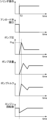
図6は、前記のように制御されるポンプ圧Pdの時間変化の例を示す。この例において、時刻t1に至るまでは前記シリンダ操作(アクチュエータ操作)が検出されておらず(ステップS12でNO)、よって前記ポンプ圧Pdは待機圧Pwtに維持される。時刻t1以降にて前記シリンダ操作(アクチュエータ操作)が検出され(ステップS12でYES)、前記コントローラ70は前記ポンプ圧Pdを前記目標圧力Pdoに追従させる制御を開始する。
FIG. 6 shows an example of a temporal change in the pump pressure Pd controlled as described above. In this example, the cylinder operation (actuator operation) is not detected until time t1 (NO in step S12), and therefore the pump pressure Pd is maintained at the standby pressure Pwt. After time t1, the cylinder operation (actuator operation) is detected (YES in step S12), and the
前記目標圧力Pdoは、前記アクチュエータ保持圧Pah(前記油圧シリンダ20に対してこれを収縮させる方向の負荷が作用しているときに当該負荷に抗して当該油圧シリンダ20を停止状態に保つためのヘッド圧センサ63Hにより検出されるヘッド圧Ph、前記油圧シリンダ20に対してこれを伸長させる方向の負荷が作用しているときに当該負荷に抗して当該油圧シリンダ20を停止状態に保つためのロッド圧センサ63Rにより検出されるロッド圧Pr)に、第1パイロット圧センサ62Aより検出されるパイロット圧の大きさに対応する操作圧ΔPopと、前記圧力損失に対応する圧力であって前記制限圧Pdrを考慮して設定された加算圧力ΔPadと、を加えた圧力に算定される。このような目標圧力Pdoに基づく制御は、前記ポンプ圧Pdが前記アクチュエータ保持圧Pahを上回ることを可能にする。
The target pressure Pdo is the actuator holding pressure Pah (for keeping the
前記コントロールバルブ30が開弁してから実際に油圧シリンダ20が動き始めるまでにはタイムラグがあるため、当該油圧シリンダ20が静止した状態のまま前記ポンプ圧Pdが上昇する。
Since there is a time lag between when the
ここでは、コントローラ70の目標圧力算定部73により算定される目標圧力Pdoに実際のポンプ圧Pdを追従させるようなアンロード操作指令をアンロード操作指令部76が生成してアンロード操作弁56に入力する。前記のような加算圧力ΔPadの設定は、前記ポンプ圧Pdが前記制限圧Pdrを超えることを阻んでサージ圧の発生の抑止を可能にする。前記制限圧Pdrは、エンジンが出力することのできるトルクの増加速度に対して、瞬間的なポンプ圧Pdの増加に対して要求されるエンジントルクの増加速度が超過することを防止できる圧力に設定される。これによって、前記油圧シリンダ20が静止した状態での前記コントロールバルブ30の急激な開弁に起因して前記ポンプ圧Pdが急激に上昇すること、すなわちサージ圧の発生、を有効に抑止することができる。
Here, the unload
そして、前記油圧シリンダ20が動き始めると、ポンプ圧Pdが低下してサージ圧の発生のおそれがさらに低下する。
Then, when the
前記油圧シリンダ20が実際に動き始めてそのシリンダ速度Scが図4に示されるように作動判定速度Scoに到達した時点(始動時点)T1で(ステップS12でNO)、アンロード操作指令部76は実際のポンプ圧Pdに関係なくアンロード弁50を全閉にするようなアンロード操作指令を生成してアンロード操作弁56に入力する(ステップS17)。これにより、油圧ポンプ10から吐出される作動油はアンロードライン51を通じて逃がされることなく油圧シリンダ20に供給される。このことは、当該油圧ポンプ10から当該油圧シリンダ20に供給される作動油の流量を増やして高いシリンダ速度Scを確保することを可能にする。
At a time T1 (starting time) when the
以上述べた効果を、図6に示す比較例に係る制御と対比しながら説明する。当該比較例に係る制御は、操作器にアクチュエータ操作が付与される時点であるアクチュエータ操作時点T2でアンロード弁を直ちに全閉にして油圧アクチュエータへの作動油の供給流量を確保する制御である。このように前記アクチュエータ操作が与えられてから前記油圧アクチュエータが動き出す前にアンロード弁がそれまでの全開の状態から全閉にされる、つまりアンロード弁の開口が急激に大きく減少する、ことにより、ポンプ圧において大きなサージ圧Psgが発生する。具体的に、前記サージ圧Psgは次式(2)で表される。 The effects described above will be explained in comparison with the control according to the comparative example shown in FIG. 6. The control according to the comparative example is such that the unload valve is immediately fully closed at the actuator operation time T2, which is the time when the actuator operation is applied to the operating device, to ensure the supply flow rate of the hydraulic oil to the hydraulic actuator. In this way, after the actuator operation is applied and before the hydraulic actuator starts moving, the unload valve is completely closed from the previously fully open state, that is, the opening of the unload valve is suddenly and greatly reduced. , a large surge pressure Psg occurs at the pump pressure. Specifically, the surge pressure Psg is expressed by the following equation (2).
Psg=ρ×c×ΔV …(2)
この式(2)において、ρは作動油の密度、cは波動伝播速度、νは作動油の流速の変化である。
Psg=ρ×c×ΔV…(2)
In this equation (2), ρ is the density of the hydraulic oil, c is the wave propagation velocity, and ν is the change in the flow velocity of the hydraulic oil.
このようなサージ圧の発生は、図6に示されるように、ポンプ流量及びポンプトルクの急増を伴い、これにより、エンジン回転数を一時的に著しく低下させるおそれがある。そのようなポンプトルクの急増を抑制する手段として、ポンプ圧の上昇に伴い可変容量型油圧ポンプのポンプ容量を減少させることが考えられるが、コントローラが油圧ポンプへの容量指令信号を変化させてから実際にポンプ容量が減少しかつトルクが低下するまでには大きな応答遅れがあるため、有効な手段とはなりにくい。 As shown in FIG. 6, the generation of such a surge pressure is accompanied by a rapid increase in pump flow rate and pump torque, which may temporarily significantly reduce the engine speed. One possible means of suppressing such a sudden increase in pump torque is to reduce the pump capacity of the variable displacement hydraulic pump as the pump pressure increases, but it is possible to reduce the pump capacity of the variable displacement hydraulic pump as the pump pressure increases. Since there is a long response delay before the pump capacity actually decreases and the torque decreases, it is difficult to find this to be an effective means.
これに対して図3及び図4に示されるような制御では、コントロールバルブ30が開弁してから実際に油圧シリンダ20が動き始めるまでの間、前記アクチュエータ保持圧Pah(ヘッド圧Phまたはロッド圧Pr)、前記操作圧、前記圧力損失に基づいて算定される目標圧力Pdoに実際のポンプ圧Pdが追従するようにアンロード弁50の開口面積が操作されるので、前記サージ圧の発生すなわち前記ポンプ圧Pdの跳ね上がりを直接的かつ有効に抑止することが可能である。
On the other hand, in the control shown in FIGS. 3 and 4, the actuator holding pressure Pah (head pressure Ph or rod pressure Pr), the opening area of the unload
さらに、前記制御では、前記油圧シリンダ20が実際に始動したとみなされる時点T1でアンロード弁50を全閉にすることにより、当該油圧シリンダ20の高い駆動速度を確保することができる。しかも、このような始動時点T1での前記アンロード弁50の全閉は、前記比較例のようなコントロールバルブ30の開弁時点におけるアンロード弁50の全閉と異なり、サージ圧の発生を伴いにくい。なぜならば、図6に示されるように、操作レバーに操作が与えられて前記ポンプの吐出量が増加されるとともに前記コントロールバルブが開弁する際に増加するポンプ圧Pdに対して、アンロード弁50を開くことによって、前記制限圧を上回る分については、上昇を回避するからである。
Further, in the control, by fully closing the unload
また、操作レバーに操作が与えられた段階においてポンプ圧Pdは少なくとも前記アクチュエータ保持圧まで上昇させるので、前記油圧シリンダ20を起動させる圧力に迅速に追従させることができ応答性の向上が図られる。
Further, since the pump pressure Pd is increased to at least the actuator holding pressure at the stage when the operation lever is operated, it can quickly follow the pressure for starting the
また、前記制御は、パイロットポート52を有するパイロット切換弁からなるアンロード弁50と、当該パイロットポート52に入力されるパイロット圧を変化させる電磁弁からなるアンロード操作弁56と、の組み合わせにより実行されるので、油圧ポンプが前記油圧ポンプ10のように可変容量型油圧ポンプからなってポンプ容量制御が可能である場合に、例えばアンロード弁にロードセンシング圧がパイロット圧として入力されることを前提とするロードセンシング制御を行う装置に比べ、適用可能なポンプ容量制御の自由度が高いという利点がある。具体的に、前記実施の形態に係る装置では、前記アンロード操作弁56を通じた前記アンロード弁50の操作によってサージ圧の抑制に有効なポンプ圧制御を行いながら、第1及び第2パイロット圧センサ62A,62Bにより検出されるパイロット圧に基づく(すなわちシリンダ操作の大きさに基づく)ポジティブコントロールや、ポンプ圧Pdに基づく馬力制御を併せて実行することが可能である。
Further, the control is executed by a combination of an unload
本発明は、以上説明した実施の形態に限定されるものではない。本発明は、例えば次のような態様を包含する。 The present invention is not limited to the embodiments described above. The present invention includes, for example, the following aspects.
(A)コントロールバルブについて
本発明に係るコントロールバルブは、操作器に与えられるアクチュエータ操作に応じて開弁動作をすることが可能なものであればよく、図1に示されるコントロールバルブ30、すなわち3位置のパイロット切換弁、に限定されない。本発明に係るコントロールバルブは、例えば、2位置切換弁であってもよく、また、電磁切換弁であってもよい。
(A) Regarding the control valve The control valve according to the present invention may be of any type as long as it can open the valve in response to an actuator operation applied to an operating device, and the
(B)操作器について
本発明に係る操作器は、オペレータによるアクチュエータ操作を受けて当該アクチュエータ操作に対応した開弁をコントロールバルブに行わせるものであればよい。本発明に係る操作器は、例えば、与えられたアクチュエータ操作を電気信号である操作信号に変換する電気レバー装置と、コントロールバルブに入力されるパイロット圧を変化させるための電磁弁と、前記操作信号に対応した開弁動作を前記コントロールバルブに行わせるように当該操作信号に対応したパイロット圧指令を前記電磁弁に入力するパイロット圧指令部と、の組み合わせによるものでもよい。
(B) Regarding the operating device The operating device according to the present invention may be any device as long as it receives an actuator operation by an operator and causes a control valve to open a valve corresponding to the actuator operation. The actuator according to the present invention includes, for example, an electric lever device that converts a given actuator operation into an operation signal that is an electric signal, a solenoid valve that changes pilot pressure input to a control valve, and the operation signal that is an electric signal. The control valve may be combined with a pilot pressure command section that inputs a pilot pressure command corresponding to the operation signal to the electromagnetic valve so as to cause the control valve to perform a valve opening operation corresponding to the operation signal.
(C)アンロード操作指令部について
本発明に係るアンロード操作指令部は、実際のポンプ圧をその目標圧力に追従させるようなアンロード操作指令を生成するものであればよく、その具体的な生成手段は限定されない。すなわち、本発明に係るアンロード操作指令部は、前記アンロード操作指令部76のように目標圧力Pdoに対するポンプ圧Pdの偏差δPdに基づいてフィードバック制御のためのアンロード操作指令を演算するものに限定されない。例えば、本発明に係るアンロード操作指令部は、入力されるポンプ圧及びアクチュエータ保持圧と出力すべきアンロード操作指令との関係を特定するために用意されたマップを格納し、当該マップを用いて前記アンロード操作指令を決定するものでもよい。すなわち、シーケンス制御が実行されてもよい。
(C) Regarding the unload operation command unit The unload operation command unit according to the present invention may be one that generates an unload operation command that causes the actual pump pressure to follow its target pressure, The generation means is not limited. That is, the unload operation command unit according to the present invention calculates an unload operation command for feedback control based on the deviation δPd of the pump pressure Pd with respect to the target pressure Pdo, like the unload
また、本発明においてアクチュエータの作動を検出するアクチュエータ作動検出器及びその検出に基づいてアンロード弁を全閉する制御は必須ではない。例えば、本発明に係るアンロード操作指令部は、アクチュエータの作動後もポンプ圧をアクチュエータ保持圧に追従させるようなアンロード操作指令の生成を続行するものでもよい。 Further, in the present invention, an actuator operation detector for detecting the operation of the actuator and control for fully closing the unload valve based on the detection are not essential. For example, the unload operation command unit according to the present invention may continue to generate an unload operation command that causes the pump pressure to follow the actuator holding pressure even after the actuator is activated.
(D)ポンプ容量制御について
本発明において、ポンプ容量制御は必須のものではない。従って、本発明に係る油圧ポンプは前記油圧ポンプ10のような可変容量型油圧ポンプに限定されず、固定容量型油圧ポンプであってもよい。
(D) Pump capacity control In the present invention, pump capacity control is not essential. Therefore, the hydraulic pump according to the present invention is not limited to a variable displacement hydraulic pump like the
10 油圧ポンプ
15 パイロットポンプ
18 可動要素
20 油圧シリンダ(油圧アクチュエータ)
30 コントロールバルブ
40 操作器
50 アンロード弁
51 アンロードライン
56 アンロード操作弁
60 ポンプ圧センサ(ポンプ圧検出器)
62A 第1パイロット圧センサ(アクチュエータ操作検出器)
62B 第2パイロット圧センサ(アクチュエータ操作検出器)
63H ヘッド圧センサ(アクチュエータ保持圧検出器)
63R ロッド圧センサ(アクチュエータ保持圧検出器)
66 シリンダ速度センサ(アクチュエータ作動検出器)
70 コントローラ
73 目標圧力算定部
76 アンロード操作指令部
78 ポンプ容量指令部
10
30
62A 1st pilot pressure sensor (actuator operation detector)
62B 2nd pilot pressure sensor (actuator operation detector)
63H Head pressure sensor (actuator holding pressure detector)
63R Rod pressure sensor (actuator holding pressure detector)
66 Cylinder speed sensor (actuator operation detector)
70
Claims (5)
作動油を吐出する油圧ポンプと、
シリンダ室を有する油圧シリンダからなり、前記可動要素に連結され、前記油圧ポンプにより吐出された作動油の供給を受けることにより前記可動要素を動かすように作動する油圧アクチュエータと、
前記油圧ポンプと前記油圧アクチュエータとの間に介在し、当該油圧ポンプから当該油圧アクチュエータへの作動油の供給を許容するように開弁することが可能なコントロールバルブと、
前記油圧アクチュエータを動かすためのアクチュエータ操作を受けることにより当該アクチュエータ操作に応じて前記コントロールバルブを開弁させる操作器と、
前記油圧ポンプにより吐出される作動油の圧力であるポンプ圧を検出するポンプ圧検出器と、
前記コントロールバルブが閉弁されているときの前記油圧アクチュエータの前記シリンダ室内の圧力であって前記油圧アクチュエータに加わる負荷に抗して当該油圧アクチュエータを停止状態に保持するのに必要な圧力であるアクチュエータ保持圧を検出するアクチュエータ保持圧検出器と、
パイロットポートを有するパイロット切換弁により構成され、前記油圧ポンプから吐出される作動油が前記コントロールバルブ及び前記油圧アクチュエータをバイパスしてタンクに直接戻ることを許容するアンロードラインに設けられ、前記パイロットポートに入力されるパイロット圧に対応した開度で開弁することにより当該開度に対応した流量で前記作動油が前記アンロードラインを流れることを可能にするアンロード弁と、
アンロード操作指令の入力を受けることが可能な電磁弁からなり、前記アンロード弁に入力される前記パイロット圧を前記アンロード操作指令に応じて変化させるように作動するアンロード操作弁と、
前記アクチュエータ保持圧検出器により検出される前記アクチュエータ保持圧に基づき前記ポンプ圧の目標圧力を算定する目標圧力算定部であって、前記目標圧力が前記油圧アクチュエータを前記負荷に抗して動かすために最低限必要な圧力以上の圧力でかつ予め設定された制限圧以下の圧力となるように当該目標圧力を算定する、目標圧力算定部と、
前記アンロード操作指令として前記ポンプ圧検出器により検出される前記ポンプ圧を前記目標圧力に追従させるような指令を生成して前記アンロード操作弁に入力するアンロード操作指令部と、を備える、作業機械の油圧駆動装置。 A hydraulic drive device installed in a working machine including a movable element for hydraulically driving the movable element,
A hydraulic pump that discharges hydraulic oil,
a hydraulic actuator , which is composed of a hydraulic cylinder having a cylinder chamber, is connected to the movable element, and operates to move the movable element by receiving a supply of hydraulic oil discharged by the hydraulic pump;
a control valve that is interposed between the hydraulic pump and the hydraulic actuator and can be opened to allow supply of hydraulic oil from the hydraulic pump to the hydraulic actuator;
an operating device that receives an actuator operation for moving the hydraulic actuator and opens the control valve in response to the actuator operation;
a pump pressure detector that detects pump pressure that is the pressure of hydraulic oil discharged by the hydraulic pump;
an actuator that is the pressure within the cylinder chamber of the hydraulic actuator when the control valve is closed and is the pressure necessary to maintain the hydraulic actuator in a stopped state against a load applied to the hydraulic actuator; an actuator holding pressure detector that detects holding pressure;
A pilot switching valve having a pilot port is provided in an unload line that allows hydraulic oil discharged from the hydraulic pump to bypass the control valve and the hydraulic actuator and directly return to the tank. an unload valve that opens at an opening corresponding to a pilot pressure input to the valve to allow the hydraulic oil to flow through the unload line at a flow rate corresponding to the opening;
an unload operation valve comprising a solenoid valve capable of receiving an input of an unload operation command, and operated to change the pilot pressure input to the unload valve in accordance with the unload operation command;
A target pressure calculation unit that calculates a target pressure of the pump pressure based on the actuator holding pressure detected by the actuator holding pressure detector, the target pressure being such that the target pressure moves the hydraulic actuator against the load. a target pressure calculation unit that calculates the target pressure so that the pressure is higher than the minimum required pressure and lower than a preset limit pressure;
an unload operation command unit that generates a command to cause the pump pressure detected by the pump pressure detector to follow the target pressure as the unload operation command and inputs the command to the unload operation valve; Hydraulic drive system for working machines.
Priority Applications (4)
| Application Number | Priority Date | Filing Date | Title |
|---|---|---|---|
| JP2020038412A JP7400552B2 (en) | 2020-03-06 | 2020-03-06 | Hydraulic drive system for working machines |
| US17/177,269 US11149757B2 (en) | 2020-03-06 | 2021-02-17 | Hydraulic drive apparatus for work machine |
| CN202110207718.8A CN113357232B (en) | 2020-03-06 | 2021-02-24 | Hydraulic drive unit of construction machinery |
| EP21159505.3A EP3875696B1 (en) | 2020-03-06 | 2021-02-26 | Hydraulic drive apparatus for work machine |
Applications Claiming Priority (1)
| Application Number | Priority Date | Filing Date | Title |
|---|---|---|---|
| JP2020038412A JP7400552B2 (en) | 2020-03-06 | 2020-03-06 | Hydraulic drive system for working machines |
Publications (2)
| Publication Number | Publication Date |
|---|---|
| JP2021139449A JP2021139449A (en) | 2021-09-16 |
| JP7400552B2 true JP7400552B2 (en) | 2023-12-19 |
Family
ID=74797763
Family Applications (1)
| Application Number | Title | Priority Date | Filing Date |
|---|---|---|---|
| JP2020038412A Active JP7400552B2 (en) | 2020-03-06 | 2020-03-06 | Hydraulic drive system for working machines |
Country Status (4)
| Country | Link |
|---|---|
| US (1) | US11149757B2 (en) |
| EP (1) | EP3875696B1 (en) |
| JP (1) | JP7400552B2 (en) |
| CN (1) | CN113357232B (en) |
Families Citing this family (6)
| Publication number | Priority date | Publication date | Assignee | Title |
|---|---|---|---|---|
| JP7236365B2 (en) * | 2019-09-20 | 2023-03-09 | 日立建機株式会社 | construction machinery |
| JP7357575B2 (en) * | 2020-03-17 | 2023-10-06 | 川崎重工業株式会社 | Control device and hydraulic system equipped with the same |
| JP7167223B2 (en) * | 2021-03-19 | 2022-11-08 | 日立建機株式会社 | hydraulic system |
| JP7815713B2 (en) * | 2021-11-30 | 2026-02-18 | コベルコ建機株式会社 | Work machinery |
| GB202117535D0 (en) * | 2021-12-03 | 2022-01-19 | Agco Int Gmbh | System and method for controlling a hydraulic supply system on a mobile machine |
| CN116816753A (en) * | 2023-07-25 | 2023-09-29 | 徐州徐工挖掘机械有限公司 | Hydraulic control system of engineering machinery and engineering machinery |
Citations (1)
| Publication number | Priority date | Publication date | Assignee | Title |
|---|---|---|---|---|
| JP2019173880A (en) | 2018-03-28 | 2019-10-10 | 株式会社日立建機ティエラ | Hydraulic drive unit of construction machine |
Family Cites Families (25)
| Publication number | Priority date | Publication date | Assignee | Title |
|---|---|---|---|---|
| JP2828490B2 (en) * | 1990-06-19 | 1998-11-25 | 日立建機株式会社 | Load sensing hydraulic drive circuit controller |
| US5222870A (en) * | 1992-06-03 | 1993-06-29 | Caterpillar Inc. | Fluid system having dual output controls |
| JPH0742705A (en) | 1993-07-30 | 1995-02-10 | Yutani Heavy Ind Ltd | Hydraulic device for operation machine |
| JPH0893705A (en) | 1994-09-29 | 1996-04-09 | Toshiba Mach Co Ltd | Hydraulic driving circuit |
| GB9503854D0 (en) | 1995-02-25 | 1995-04-19 | Ultra Hydraulics Ltd | Electrohydraulic proportional control valve assemblies |
| US5680760A (en) * | 1996-03-28 | 1997-10-28 | Caterpillar Inc. | Hydraulic drive system |
| JP3535667B2 (en) * | 1996-08-24 | 2004-06-07 | コベルコ建機株式会社 | Hydraulic drive for construction machinery |
| JP2000170212A (en) * | 1998-07-07 | 2000-06-20 | Yutani Heavy Ind Ltd | Hydraulic control equipment for work machines |
| US6173572B1 (en) * | 1999-09-23 | 2001-01-16 | Caterpillar Inc. | Method and apparatus for controlling a bypass valve of a fluid circuit |
| JP2004347040A (en) | 2003-05-22 | 2004-12-09 | Kobelco Contstruction Machinery Ltd | Controller of working vehicle |
| JP4839928B2 (en) | 2006-03-31 | 2011-12-21 | コベルコ建機株式会社 | Hydraulic control equipment for construction machinery |
| JP2008180287A (en) | 2007-01-24 | 2008-08-07 | Kobelco Contstruction Machinery Ltd | Hydraulic control device of construction machine |
| KR101908547B1 (en) * | 2011-08-26 | 2018-12-18 | 볼보 컨스트럭션 이큅먼트 에이비 | Drive control method and system for operating a hydraulic driven work machine |
| JP5878811B2 (en) * | 2012-04-10 | 2016-03-08 | 日立建機株式会社 | Hydraulic drive unit for construction machinery |
| JP6089665B2 (en) * | 2012-12-13 | 2017-03-08 | コベルコ建機株式会社 | Hydraulic control equipment for construction machinery |
| JP6122765B2 (en) * | 2013-11-01 | 2017-04-26 | 日立建機株式会社 | Work machine |
| JP6279356B2 (en) * | 2014-03-10 | 2018-02-14 | 株式会社神戸製鋼所 | Hydraulic drive device for work machine |
| JP6131295B2 (en) * | 2015-06-18 | 2017-05-17 | 株式会社神戸製鋼所 | Hydraulic control device for work machine |
| JP6565614B2 (en) * | 2015-11-06 | 2019-08-28 | コベルコ建機株式会社 | Swivel hydraulic work machine |
| JP6487872B2 (en) * | 2016-03-30 | 2019-03-20 | 日立建機株式会社 | Drive control device for work machine |
| JP6845736B2 (en) * | 2017-04-28 | 2021-03-24 | 川崎重工業株式会社 | Hydraulic drive system |
| JP6853740B2 (en) * | 2017-06-16 | 2021-03-31 | 川崎重工業株式会社 | Hydraulic system |
| GB2585752B (en) * | 2018-05-21 | 2022-10-12 | Kawasaki Heavy Ind Ltd | Hydraulic drive system of construction machine |
| JP7131138B2 (en) * | 2018-07-04 | 2022-09-06 | コベルコ建機株式会社 | Working machine hydraulic drive |
| JP7141038B2 (en) | 2018-08-31 | 2022-09-22 | 株式会社Nttドコモ | Onset prediction device and onset prediction system |
-
2020
- 2020-03-06 JP JP2020038412A patent/JP7400552B2/en active Active
-
2021
- 2021-02-17 US US17/177,269 patent/US11149757B2/en active Active
- 2021-02-24 CN CN202110207718.8A patent/CN113357232B/en active Active
- 2021-02-26 EP EP21159505.3A patent/EP3875696B1/en active Active
Patent Citations (1)
| Publication number | Priority date | Publication date | Assignee | Title |
|---|---|---|---|---|
| JP2019173880A (en) | 2018-03-28 | 2019-10-10 | 株式会社日立建機ティエラ | Hydraulic drive unit of construction machine |
Also Published As
| Publication number | Publication date |
|---|---|
| US20210277630A1 (en) | 2021-09-09 |
| CN113357232A (en) | 2021-09-07 |
| EP3875696A1 (en) | 2021-09-08 |
| US11149757B2 (en) | 2021-10-19 |
| EP3875696B1 (en) | 2022-11-30 |
| JP2021139449A (en) | 2021-09-16 |
| CN113357232B (en) | 2026-03-24 |
Similar Documents
| Publication | Publication Date | Title |
|---|---|---|
| JP7400552B2 (en) | Hydraulic drive system for working machines | |
| JP3664733B2 (en) | Hydraulic drive | |
| EP2351936B1 (en) | Hydraulic drive device for construction machine | |
| US7296404B2 (en) | Apparatus for controlling deceleration of hydraulically powered equipment | |
| CN110520635A (en) | Fluid power system | |
| JP4746750B2 (en) | Method and apparatus for controlling dead zone of fluid system | |
| WO2000001896A1 (en) | Hydraulic control device of working machine | |
| JPH07127607A (en) | Hydraulic device of work machine | |
| CN110325747B (en) | work machinery | |
| JPH0450504A (en) | Controller for load sensing hydraulic drive circuit | |
| US6199378B1 (en) | Off-setting rate of pressure rise in a fluid system | |
| WO1998031926A1 (en) | Controller of engine and variable capacity pump | |
| US12173475B2 (en) | Work machine | |
| JP2010151191A (en) | Hydraulic system of working machine | |
| JP3730336B2 (en) | Hydraulic actuator speed control device | |
| JP3344023B2 (en) | Hydraulic control equipment for work machines | |
| JP2006177402A (en) | Hydraulic circuit of construction machinery | |
| JP4973047B2 (en) | Hydraulic control circuit for work machines | |
| JP2003184805A (en) | Top swing type work vehicle | |
| JP2871871B2 (en) | Hydraulic drive for construction machinery | |
| JP2002295409A (en) | Hydraulic working machine | |
| RU2761503C1 (en) | Electrohydraulic control system | |
| CN113748246B (en) | Working equipment | |
| JP3137318B2 (en) | Control device for hydraulic drive machine | |
| JP2025144462A (en) | Work machinery |
Legal Events
| Date | Code | Title | Description |
|---|---|---|---|
| A621 | Written request for application examination |
Free format text: JAPANESE INTERMEDIATE CODE: A621 Effective date: 20221012 |
|
| A131 | Notification of reasons for refusal |
Free format text: JAPANESE INTERMEDIATE CODE: A131 Effective date: 20230530 |
|
| A977 | Report on retrieval |
Free format text: JAPANESE INTERMEDIATE CODE: A971007 Effective date: 20230531 |
|
| A521 | Request for written amendment filed |
Free format text: JAPANESE INTERMEDIATE CODE: A523 Effective date: 20230728 |
|
| TRDD | Decision of grant or rejection written | ||
| A01 | Written decision to grant a patent or to grant a registration (utility model) |
Free format text: JAPANESE INTERMEDIATE CODE: A01 Effective date: 20231107 |
|
| A61 | First payment of annual fees (during grant procedure) |
Free format text: JAPANESE INTERMEDIATE CODE: A61 Effective date: 20231120 |
|
| R150 | Certificate of patent or registration of utility model |
Ref document number: 7400552 Country of ref document: JP Free format text: JAPANESE INTERMEDIATE CODE: R150 |