RU2756986C2 - Wound closure device with the creation of negative pressure - Google Patents
Wound closure device with the creation of negative pressure Download PDFInfo
- Publication number
- RU2756986C2 RU2756986C2 RU2017106796A RU2017106796A RU2756986C2 RU 2756986 C2 RU2756986 C2 RU 2756986C2 RU 2017106796 A RU2017106796 A RU 2017106796A RU 2017106796 A RU2017106796 A RU 2017106796A RU 2756986 C2 RU2756986 C2 RU 2756986C2
- Authority
- RU
- Russia
- Prior art keywords
- wound
- filler
- tissue
- stabilizing
- compression
- Prior art date
Links
- 239000000945 filler Substances 0.000 claims abstract description 170
- 210000001519 tissue Anatomy 0.000 claims description 130
- 238000000034 method Methods 0.000 claims description 82
- 230000000087 stabilizing effect Effects 0.000 claims description 68
- 239000000463 material Substances 0.000 claims description 46
- 238000007906 compression Methods 0.000 claims description 43
- 230000006835 compression Effects 0.000 claims description 43
- 239000012530 fluid Substances 0.000 claims description 22
- 230000002093 peripheral effect Effects 0.000 claims description 22
- 239000011148 porous material Substances 0.000 claims description 20
- 238000000418 atomic force spectrum Methods 0.000 claims description 19
- 239000003381 stabilizer Substances 0.000 claims description 15
- 238000009826 distribution Methods 0.000 claims description 9
- 238000000926 separation method Methods 0.000 claims description 7
- 125000006850 spacer group Chemical group 0.000 claims description 7
- 239000006260 foam Substances 0.000 claims description 6
- 210000000577 adipose tissue Anatomy 0.000 claims description 4
- 230000001413 cellular effect Effects 0.000 claims description 4
- 210000003205 muscle Anatomy 0.000 claims description 4
- 210000003491 skin Anatomy 0.000 claims description 4
- 210000000683 abdominal cavity Anatomy 0.000 claims description 3
- 206010052428 Wound Diseases 0.000 abstract description 199
- 208000027418 Wounds and injury Diseases 0.000 abstract description 198
- 230000029663 wound healing Effects 0.000 abstract description 9
- 238000001356 surgical procedure Methods 0.000 abstract description 4
- 230000000694 effects Effects 0.000 abstract description 2
- 230000000737 periodic effect Effects 0.000 abstract description 2
- 239000003814 drug Substances 0.000 abstract 1
- 239000000126 substance Substances 0.000 abstract 1
- 230000014759 maintenance of location Effects 0.000 description 14
- 230000008602 contraction Effects 0.000 description 7
- 230000035876 healing Effects 0.000 description 7
- 239000010410 layer Substances 0.000 description 6
- 230000008859 change Effects 0.000 description 5
- 238000004873 anchoring Methods 0.000 description 4
- 238000009581 negative-pressure wound therapy Methods 0.000 description 4
- 230000008569 process Effects 0.000 description 4
- 0 CC(*1C*(C)CC1)C(C)(*)*[C@](C)(*)C(*)[C@@](C)C(C)(**)C(C)=C[C@]([C@@](C)F)C1IC(C)*1 Chemical compound CC(*1C*(C)CC1)C(C)(*)*[C@](C)(*)C(*)[C@@](C)C(C)(**)C(C)=C[C@]([C@@](C)F)C1IC(C)*1 0.000 description 3
- 108010035532 Collagen Proteins 0.000 description 3
- 102000008186 Collagen Human genes 0.000 description 3
- 210000001015 abdomen Anatomy 0.000 description 3
- 229920001436 collagen Polymers 0.000 description 3
- 241001465754 Metazoa Species 0.000 description 2
- 229920005830 Polyurethane Foam Polymers 0.000 description 2
- 230000003187 abdominal effect Effects 0.000 description 2
- 230000008901 benefit Effects 0.000 description 2
- 230000015572 biosynthetic process Effects 0.000 description 2
- 239000011248 coating agent Substances 0.000 description 2
- 238000000576 coating method Methods 0.000 description 2
- 238000005520 cutting process Methods 0.000 description 2
- 239000013013 elastic material Substances 0.000 description 2
- 239000004744 fabric Substances 0.000 description 2
- 230000006872 improvement Effects 0.000 description 2
- 239000008188 pellet Substances 0.000 description 2
- 239000011496 polyurethane foam Substances 0.000 description 2
- 239000012781 shape memory material Substances 0.000 description 2
- 238000007920 subcutaneous administration Methods 0.000 description 2
- 241000894006 Bacteria Species 0.000 description 1
- 239000004604 Blowing Agent Substances 0.000 description 1
- 206010063560 Excessive granulation tissue Diseases 0.000 description 1
- 206010061218 Inflammation Diseases 0.000 description 1
- 206010030113 Oedema Diseases 0.000 description 1
- 208000004210 Pressure Ulcer Diseases 0.000 description 1
- 206010072170 Skin wound Diseases 0.000 description 1
- 208000002847 Surgical Wound Diseases 0.000 description 1
- 238000012084 abdominal surgery Methods 0.000 description 1
- 239000000560 biocompatible material Substances 0.000 description 1
- 238000005266 casting Methods 0.000 description 1
- 239000003054 catalyst Substances 0.000 description 1
- 230000000295 complement effect Effects 0.000 description 1
- 239000002131 composite material Substances 0.000 description 1
- 239000000470 constituent Substances 0.000 description 1
- 230000016396 cytokine production Effects 0.000 description 1
- 230000006378 damage Effects 0.000 description 1
- 230000023753 dehiscence Effects 0.000 description 1
- 210000004207 dermis Anatomy 0.000 description 1
- 230000006870 function Effects 0.000 description 1
- 210000005095 gastrointestinal system Anatomy 0.000 description 1
- 210000001126 granulation tissue Anatomy 0.000 description 1
- 230000004054 inflammatory process Effects 0.000 description 1
- 230000002401 inhibitory effect Effects 0.000 description 1
- 238000009434 installation Methods 0.000 description 1
- 210000000936 intestine Anatomy 0.000 description 1
- 230000001788 irregular Effects 0.000 description 1
- 208000028867 ischemia Diseases 0.000 description 1
- 239000012948 isocyanate Substances 0.000 description 1
- 150000002513 isocyanates Chemical class 0.000 description 1
- 238000005304 joining Methods 0.000 description 1
- 239000007788 liquid Substances 0.000 description 1
- 238000004519 manufacturing process Methods 0.000 description 1
- 210000001370 mediastinum Anatomy 0.000 description 1
- 239000000203 mixture Substances 0.000 description 1
- 230000037311 normal skin Effects 0.000 description 1
- 108010003992 parietex Proteins 0.000 description 1
- 230000035515 penetration Effects 0.000 description 1
- 238000000554 physical therapy Methods 0.000 description 1
- 239000004033 plastic Substances 0.000 description 1
- 229920003023 plastic Polymers 0.000 description 1
- 229920000728 polyester Polymers 0.000 description 1
- 229920005862 polyol Polymers 0.000 description 1
- 150000003077 polyols Chemical class 0.000 description 1
- 239000000376 reactant Substances 0.000 description 1
- 230000009467 reduction Effects 0.000 description 1
- 230000008439 repair process Effects 0.000 description 1
- 239000012791 sliding layer Substances 0.000 description 1
- 239000004094 surface-active agent Substances 0.000 description 1
- 238000002560 therapeutic procedure Methods 0.000 description 1
- 230000000451 tissue damage Effects 0.000 description 1
- 231100000827 tissue damage Toxicity 0.000 description 1
- 238000011144 upstream manufacturing Methods 0.000 description 1
- 210000001835 viscera Anatomy 0.000 description 1
Images
Classifications
-
- A—HUMAN NECESSITIES
- A61—MEDICAL OR VETERINARY SCIENCE; HYGIENE
- A61B—DIAGNOSIS; SURGERY; IDENTIFICATION
- A61B17/00—Surgical instruments, devices or methods, e.g. tourniquets
- A61B17/08—Wound clamps or clips, i.e. not or only partly penetrating the tissue ; Devices for bringing together the edges of a wound
-
- A61F13/05—
-
- A—HUMAN NECESSITIES
- A61—MEDICAL OR VETERINARY SCIENCE; HYGIENE
- A61B—DIAGNOSIS; SURGERY; IDENTIFICATION
- A61B17/00—Surgical instruments, devices or methods, e.g. tourniquets
-
- A—HUMAN NECESSITIES
- A61—MEDICAL OR VETERINARY SCIENCE; HYGIENE
- A61B—DIAGNOSIS; SURGERY; IDENTIFICATION
- A61B17/00—Surgical instruments, devices or methods, e.g. tourniquets
- A61B17/0057—Implements for plugging an opening in the wall of a hollow or tubular organ, e.g. for sealing a vessel puncture or closing a cardiac septal defect
-
- A—HUMAN NECESSITIES
- A61—MEDICAL OR VETERINARY SCIENCE; HYGIENE
- A61M—DEVICES FOR INTRODUCING MEDIA INTO, OR ONTO, THE BODY; DEVICES FOR TRANSDUCING BODY MEDIA OR FOR TAKING MEDIA FROM THE BODY; DEVICES FOR PRODUCING OR ENDING SLEEP OR STUPOR
- A61M1/00—Suction or pumping devices for medical purposes; Devices for carrying-off, for treatment of, or for carrying-over, body-liquids; Drainage systems
- A61M1/08—Cupping glasses, i.e. for enhancing blood circulation
-
- A—HUMAN NECESSITIES
- A61—MEDICAL OR VETERINARY SCIENCE; HYGIENE
- A61M—DEVICES FOR INTRODUCING MEDIA INTO, OR ONTO, THE BODY; DEVICES FOR TRANSDUCING BODY MEDIA OR FOR TAKING MEDIA FROM THE BODY; DEVICES FOR PRODUCING OR ENDING SLEEP OR STUPOR
- A61M1/00—Suction or pumping devices for medical purposes; Devices for carrying-off, for treatment of, or for carrying-over, body-liquids; Drainage systems
- A61M1/84—Drainage tubes; Aspiration tips
-
- A—HUMAN NECESSITIES
- A61—MEDICAL OR VETERINARY SCIENCE; HYGIENE
- A61M—DEVICES FOR INTRODUCING MEDIA INTO, OR ONTO, THE BODY; DEVICES FOR TRANSDUCING BODY MEDIA OR FOR TAKING MEDIA FROM THE BODY; DEVICES FOR PRODUCING OR ENDING SLEEP OR STUPOR
- A61M1/00—Suction or pumping devices for medical purposes; Devices for carrying-off, for treatment of, or for carrying-over, body-liquids; Drainage systems
- A61M1/90—Negative pressure wound therapy devices, i.e. devices for applying suction to a wound to promote healing, e.g. including a vacuum dressing
-
- A—HUMAN NECESSITIES
- A61—MEDICAL OR VETERINARY SCIENCE; HYGIENE
- A61B—DIAGNOSIS; SURGERY; IDENTIFICATION
- A61B17/00—Surgical instruments, devices or methods, e.g. tourniquets
- A61B2017/00535—Surgical instruments, devices or methods, e.g. tourniquets pneumatically or hydraulically operated
- A61B2017/00561—Surgical instruments, devices or methods, e.g. tourniquets pneumatically or hydraulically operated creating a vacuum
-
- A—HUMAN NECESSITIES
- A61—MEDICAL OR VETERINARY SCIENCE; HYGIENE
- A61B—DIAGNOSIS; SURGERY; IDENTIFICATION
- A61B17/00—Surgical instruments, devices or methods, e.g. tourniquets
- A61B17/0057—Implements for plugging an opening in the wall of a hollow or tubular organ, e.g. for sealing a vessel puncture or closing a cardiac septal defect
- A61B2017/00646—Type of implements
- A61B2017/00654—Type of implements entirely comprised between the two sides of the opening
-
- A—HUMAN NECESSITIES
- A61—MEDICAL OR VETERINARY SCIENCE; HYGIENE
- A61B—DIAGNOSIS; SURGERY; IDENTIFICATION
- A61B17/00—Surgical instruments, devices or methods, e.g. tourniquets
- A61B17/08—Wound clamps or clips, i.e. not or only partly penetrating the tissue ; Devices for bringing together the edges of a wound
- A61B2017/081—Tissue approximator
-
- A—HUMAN NECESSITIES
- A61—MEDICAL OR VETERINARY SCIENCE; HYGIENE
- A61F—FILTERS IMPLANTABLE INTO BLOOD VESSELS; PROSTHESES; DEVICES PROVIDING PATENCY TO, OR PREVENTING COLLAPSING OF, TUBULAR STRUCTURES OF THE BODY, e.g. STENTS; ORTHOPAEDIC, NURSING OR CONTRACEPTIVE DEVICES; FOMENTATION; TREATMENT OR PROTECTION OF EYES OR EARS; BANDAGES, DRESSINGS OR ABSORBENT PADS; FIRST-AID KITS
- A61F13/00—Bandages or dressings; Absorbent pads
- A61F2013/00089—Wound bandages
- A61F2013/0017—Wound bandages possibility of applying fluid
- A61F2013/00174—Wound bandages possibility of applying fluid possibility of applying pressure
-
- A—HUMAN NECESSITIES
- A61—MEDICAL OR VETERINARY SCIENCE; HYGIENE
- A61F—FILTERS IMPLANTABLE INTO BLOOD VESSELS; PROSTHESES; DEVICES PROVIDING PATENCY TO, OR PREVENTING COLLAPSING OF, TUBULAR STRUCTURES OF THE BODY, e.g. STENTS; ORTHOPAEDIC, NURSING OR CONTRACEPTIVE DEVICES; FOMENTATION; TREATMENT OR PROTECTION OF EYES OR EARS; BANDAGES, DRESSINGS OR ABSORBENT PADS; FIRST-AID KITS
- A61F13/00—Bandages or dressings; Absorbent pads
- A61F2013/00361—Plasters
- A61F2013/00365—Plasters use
- A61F2013/00536—Plasters use for draining or irrigating wounds
-
- A—HUMAN NECESSITIES
- A61—MEDICAL OR VETERINARY SCIENCE; HYGIENE
- A61F—FILTERS IMPLANTABLE INTO BLOOD VESSELS; PROSTHESES; DEVICES PROVIDING PATENCY TO, OR PREVENTING COLLAPSING OF, TUBULAR STRUCTURES OF THE BODY, e.g. STENTS; ORTHOPAEDIC, NURSING OR CONTRACEPTIVE DEVICES; FOMENTATION; TREATMENT OR PROTECTION OF EYES OR EARS; BANDAGES, DRESSINGS OR ABSORBENT PADS; FIRST-AID KITS
- A61F13/00—Bandages or dressings; Absorbent pads
- A61F2013/00361—Plasters
- A61F2013/00365—Plasters use
- A61F2013/0054—Plasters use for deep wounds
-
- A—HUMAN NECESSITIES
- A61—MEDICAL OR VETERINARY SCIENCE; HYGIENE
- A61F—FILTERS IMPLANTABLE INTO BLOOD VESSELS; PROSTHESES; DEVICES PROVIDING PATENCY TO, OR PREVENTING COLLAPSING OF, TUBULAR STRUCTURES OF THE BODY, e.g. STENTS; ORTHOPAEDIC, NURSING OR CONTRACEPTIVE DEVICES; FOMENTATION; TREATMENT OR PROTECTION OF EYES OR EARS; BANDAGES, DRESSINGS OR ABSORBENT PADS; FIRST-AID KITS
- A61F13/00—Bandages or dressings; Absorbent pads
- A61F2013/00361—Plasters
- A61F2013/00544—Plasters form or structure
- A61F2013/00548—Plasters form or structure net
-
- A—HUMAN NECESSITIES
- A61—MEDICAL OR VETERINARY SCIENCE; HYGIENE
- A61M—DEVICES FOR INTRODUCING MEDIA INTO, OR ONTO, THE BODY; DEVICES FOR TRANSDUCING BODY MEDIA OR FOR TAKING MEDIA FROM THE BODY; DEVICES FOR PRODUCING OR ENDING SLEEP OR STUPOR
- A61M1/00—Suction or pumping devices for medical purposes; Devices for carrying-off, for treatment of, or for carrying-over, body-liquids; Drainage systems
- A61M1/90—Negative pressure wound therapy devices, i.e. devices for applying suction to a wound to promote healing, e.g. including a vacuum dressing
- A61M1/91—Suction aspects of the dressing
- A61M1/916—Suction aspects of the dressing specially adapted for deep wounds
Abstract
Description
Ссылки на родственные заявкиLinks to related claims
Согласно настоящей заявке испрашивается приоритет в соответствии с предварительной заявкой на выдачу патента США No 61/439525, поданной 4 февраля 2011 г. Содержание вышеприведенной заявки полностью включено в настоящую заявку посредством ссылки.This application claims priority in accordance with provisional application for the grant of US patent No. 61/439525, filed February 4, 2011. The contents of the above application are fully incorporated into this application by reference.
Уровень техникиState of the art
Целый ряд способов был разработан для лечения ран, включая раны, полученные в результате несчастных случаев, и раны, полученные в результате оперативного вмешательства. Часто раны закрывают с применением хирургических нитей или скоб. Однако применение этих механических способов закрытия требует выполнения дополнительных проколов или ран на коже, что может вести к повреждению ткани, а в случае избыточного отека к вероятной ишемии и потере ткани. Кроме того, механические средства закрытия раны, такие как скобы и хирургические нити, могут быть причиной высоко локализированных напряжений в точках фиксации, которые могут затруднять и нарушать нормальные процессы заживления раны кожи.A number of methods have been developed for the treatment of wounds, including wounds resulting from accidents and wounds resulting from surgery. Often, wounds are closed using sutures or staples. However, the use of these mechanical closure methods requires additional punctures or wounds in the skin, which can lead to tissue damage and, in the case of excessive edema, possible ischemia and tissue loss. In addition, mechanical wound closures such as staples and surgical sutures can cause highly localized stresses at the fixation points that can impede and disrupt normal skin wound healing processes.
В последние годы вырос интерес к применению устройств с созданием отрицательного давления для лечения ран. При лечении ран с созданием отрицательного давления используют устройства, которые удаляют жидкости из раны посредством применения к ране отсасывания с созданием отрицательного давления. Считается, что такие значения отрицательного давления способствуют заживлению раны посредством облегчения образования грануляционной ткани в зоне раны и способствуют нормальному воспалительному процессу тела при одновременном удалении излишней жидкости, которая может содержать неблагоприятные для производства цитокинов бактерии. Тем не менее, требуются дальнейшие улучшения в терапии ран с созданием отрицательного давления для того, чтобы полностью реализовать преимущества лечения.In recent years, interest has grown in the use of negative pressure devices for wound healing. Negative pressure wound healing uses devices that remove fluid from the wound by applying negative pressure suction to the wound. Such negative pressure values are believed to promote wound healing by facilitating the formation of granulation tissue in the wound area and to promote normal body inflammation while removing excess fluid that may contain bacteria that are unfavorable for cytokine production. However, further improvements are required in negative pressure wound therapy in order to fully realize the benefits of treatment.
Сущность изобретенияThe essence of the invention
Настоящее изобретение относится к устройству закрытия раны с созданием отрицательного давления, которое конкретно прикладывает силу к краям раны для того, чтобы способствовать закрытию раны. Устройство функционирует с целью снижения потребности в периодической замене наполнителя, используемого в настоящее время, и может повышать скорость заживления. В устройстве одновременно используют отрицательное давление для удаления жидкостей из раны.The present invention relates to a negative pressure wound closure device that specifically applies force to the edges of a wound in order to facilitate wound closure. The device functions to reduce the need for periodic replacement of the filler currently in use and may increase the rate of healing. The device simultaneously uses negative pressure to remove fluids from the wound.
Согласно одному варианту осуществления устройство закрытия раны с созданием отрицательного давления содержит наполнитель раны, который характеризуется такими размерами и формой, чтобы помещаться в отверстии раны, и который сокращается вдоль по меньшей мере одного направления при приложении отрицательного давления к наполнителю. Таким образом, наполнитель сконфигурирован так, чтобы сокращаться предпочтительно по меньшей мере в одном направлении и препятствовать сокращениям в одном или нескольких дополнительных направлениях. Устройства с созданием отрицательного давления, известные из уровня техники, не способствовали закрытию раны, а применялись для дренирования жидкостей. Согласно настоящему изобретению существенное улучшение в скорости заживления может быть осуществлено посредством обеспечения управляемого движения ткани во время процесса заживления совместно с дренированием жидкостей из ран. Следует отметить, что в зависимости от размера раны может быть применено повышенное отрицательное давление.In one embodiment, a negative pressure wound closure device comprises a wound filler sized and shaped to fit within a wound opening and which contracts along at least one direction when negative pressure is applied to the filler material. Thus, the filler is configured to contract, preferably in at least one direction, and to resist contracting in one or more additional directions. Negative pressure devices known in the art did not help close the wound but were used to drain fluids. According to the present invention, a significant improvement in the rate of healing can be brought about by providing controlled movement of tissue during the healing process in conjunction with the drainage of fluids from the wounds. It should be noted that depending on the size of the wound, increased negative pressure may be applied.
Согласно другому предпочтительному варианту осуществления поверхность захватывания ткани проходит вдоль внешней периферийной поверхности наполнителя раны и содержит множество фиксаторов ткани, которые входят в зацепление с тканью на границе раны. При приложении отрицательного давления происходит перемещение ткани на границе раны для того, чтобы способствовать закрытию раны. Источник отрицательного давления, например, вакуумный насос, подключен к наполнителю раны для обеспечения отрицательного давления.In another preferred embodiment, the tissue grasping surface extends along the outer peripheral surface of the wound filler and comprises a plurality of tissue anchors that engage tissue at the wound boundary. When negative pressure is applied, tissue is displaced at the wound border in order to facilitate wound closure. A negative pressure source, such as a vacuum pump, is connected to the wound filler to provide negative pressure.
Наполнитель раны, как правило, содержит пористый материал, такой как пена. Согласно вариантам осуществления, в которых применяют фиксаторы ткани, они могут быть выполнены как одно целое с наполнителем. Согласно другим вариантам осуществления фиксаторы ткани выполняют на отдельном покрытии или пленке, которая прикреплена к наполнителю.The wound filler usually contains a porous material such as foam. In embodiments that use tissue anchors, they may be integral with the filler. In other embodiments, the tissue anchors are provided on a separate cover or film that is attached to the filler.
Согласно предпочтительным вариантам осуществления наполнитель содержит стабилизирующую структуру, которая обеспечивает сжатие материала по меньшей мере в одном первом направлении и препятствует сжатию по меньшей мере в одном втором направлении. Стабилизирующая структура может содержать области относительно жесткого материала, окруженные областями относительно сжимаемого материала. Согласно предпочтительным вариантам осуществления стабилизирующая структура представляет собой эндоскелет, выполненный из жесткого и/или полужесткого материалов.In preferred embodiments, the filler comprises a stabilizing structure that compresses the material in at least one first direction and resists compression in at least one second direction. The stabilizing structure may comprise regions of relatively rigid material surrounded by regions of relatively compressible material. In preferred embodiments, the stabilizing structure is an endoskeleton made of rigid and / or semi-rigid materials.
Согласно определенным вариантам осуществления стабилизирующая структура препятствует сжатию наполнителя вдоль его высоты, при этом допуская сжатие наполнителя в плоскости, ограниченной границами раны. Это является полезным, например, в случае хирургической операции на брюшной полости, при которой хирургический разрез выполняют вдоль прямой линии для формирования раны овальной формы. Указанная рана, как правило, овальной формы, может проходить через мышечную и жировую ткань, которые характеризуются различными механическими свойствами. Для заживления раны лучше подходит применение структуры овальной формы, приспособленной предпочтительно для сжатия по направлению к изначальной линии разреза. Согласно предпочтительным вариантам осуществления стабилизирующая структура способствует сжатию наполнителя таким образом, чтобы вызывать сближение ткани раны. Раны при фасциотомии, или другие расхождения краев раны, или любая открытая рана могут успешно быть вылечены посредством применения вариантов осуществления настоящего изобретения.In certain embodiments, the stabilizing structure resists compression of the filler along its height while allowing compression of the filler in the plane bounded by the wound boundaries. This is useful, for example, in the case of abdominal surgery in which the surgical incision is made along a straight line to form an oval wound. The specified wound, as a rule, is oval in shape, can pass through muscle and adipose tissue, which are characterized by different mechanical properties. For wound healing, it is better to use an oval-shaped structure, preferably adapted to compress towards the original incision line. In preferred embodiments, the stabilizing structure contributes to the compression of the filler so as to bring the wound tissue closer together. Fasciotomy wounds, or other dehiscence of the wound edges, or any open wound, can be successfully treated using embodiments of the present invention.
Устройство закрытия раны может быть применено для лечения ран в средостении, для пролежневых язв, для ран конечностей (рук или ног) и т.п. Устройство закрытия раны также может быть применено для лечения ран различных форм, например, ран круглой, квадратной, прямоугольной или неправильной форм. Несколько элементов закрытия раны могут характеризоваться такой формой, чтобы поместится в ране, при этом они могут быть прикреплены друг к другу предпочтительно для закрытия раны в желаемом направлении. Разные элементы могут содержать разные материалы или обладать различными характеристиками, такими как размер пор и/или размер и распределение фиксаторов, для формирования составной конструкции.The wound closure device can be used to treat wounds in the mediastinum, for pressure ulcers, for wounds of the extremities (arms or legs), and the like. The wound closure device can also be used to treat wounds of various shapes, such as round, square, rectangular or irregular wounds. The plurality of wound closure members can be shaped to fit into a wound and can be attached to one another, preferably to close the wound in a desired direction. Different elements can contain different materials or have different characteristics, such as pore size and / or the size and distribution of anchors, to form a composite structure.
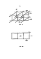
Согласно одному варианту осуществления стабилизирующая структура эндоскелета содержит множество расположенных на расстоянии друг от друга жестких элементов, образующих решетчатую конфигурацию. Эндоскелет позволяет наполнителю сжиматься вдоль его ширины и удлиняться на меньшую величину вдоль его длины. Например, согласно определенным вариантам осуществления множество жестких элементов проходит вдоль высоты наполнителя и препятствует сжатию материала вдоль его высоты. Согласно определенным вариантам осуществления эндоскелет содержит сеть взаимосвязанных жестких элементов, которые могут быть повернуты по отношению друг к другу во время сжатия наполнителя. Эндоскелет может содержать опорные элементы в виде распорок для препятствования наклону наполнителя. Согласно некоторым вариантам осуществления фиксаторы ткани могут быть выполнены как одно целое с эндоскелетом.In one embodiment, the stabilizing structure of the endoskeleton comprises a plurality of spaced-apart rigid elements forming a lattice configuration. The endoskeleton allows the filler to contract along its width and lengthen less along its length. For example, in certain embodiments, a plurality of rigid members extend along the height of the filler and resist compression of the material along its height. In certain embodiments, the endoskeleton comprises a network of interconnected rigid members that can be rotated relative to each other during compression of the filler. The endoskeleton may contain support elements in the form of struts to prevent the filler from tilting. In some embodiments, tissue anchors may be integral with the endoskeleton.
Согласно определенным вариантам осуществления наполнитель раны содержит гладкую нижнюю поверхность, содержащую микропоры для обеспечения прохождения жидкости из раны через нижнюю поверхность и далее в устройство для удаления. Микропоры могут характеризоваться переменными размерами пор и/или плотностью пор для осуществления распределения силы разрежения от источника отрицательного давления. Согласно некоторым вариантам осуществления наполнитель раны может характеризоваться переменными внутренними размерами пор и/или плотностью пор для осуществления распределения силы разрежения.In certain embodiments, the wound filler comprises a smooth bottom surface containing micropores to allow fluid to pass from the wound through the bottom surface and on to the disposal device. Micropores can be characterized by variable pore sizes and / or pore density to distribute the rarefaction force from a negative pressure source. In some embodiments, the wound filler may have variable internal pore sizes and / or pore density to effect distribution of the vacuum force.
Согласно одному варианту осуществления компонент для лечения ран с созданием отрицательного давления для управления жидкостью и/или ее удаления соединен с наполнителем раны. Один источник отрицательного давления может быть использован для закрытия раны и управления жидкостью/дренирования. Поверхность скольжения обеспечена на границе контакта между компонентами закрытия раны и управления жидкостью.In one embodiment, the negative pressure wound treatment component for fluid management and / or removal is coupled to the wound filler. A single negative pressure source can be used for wound closure and fluid management / drainage. A sliding surface is provided at the interface between the wound closure and fluid control components.
Согласно еще одному варианту осуществления наполнитель содержит удаляемые участки для корректировки размера устройства закрытия раны. Наполнитель может быть выполнен с предварительно определенными линиями разделения для отрывания или отрезания участков материала. Согласно определенным вариантам осуществления ряды фиксаторов ткани погружены в наполнитель и становятся доступными посредством удаления избыточных участков материала.In another embodiment, the filler comprises removable areas for adjusting the size of the wound closure device. The filler can be configured with predetermined separation lines for tearing or cutting off portions of the material. In certain embodiments, the rows of tissue anchors are immersed in the filler and made available by removing excess material.
Согласно другому варианту осуществления фиксаторы ткани характеризуются изменяющимся профилем силы. Профиль силы может изменяться на основании глубины ткани или типа ткани, с которой происходит взаимодействие. Согласно некоторым вариантам осуществления профиль силы поверхности захватывания ткани изменяется по периметру устройства закрытия раны. Профиль силы изменяют, например, посредством изменения одного или более из длины фиксаторов ткани, формы фиксаторов, материалов фиксаторов и плотности фиксаторов.In another embodiment, tissue anchors have a varying force profile. The force profile can change based on the depth of the tissue or the type of tissue with which it interacts. In some embodiments, the force profile of the tissue grasping surface changes around the perimeter of the wound closure device. The force profile is altered, for example, by changing one or more of the length of the tissue anchors, the shape of the anchors, the materials of the anchors, and the density of the anchors.
Настоящее изобретение также относится к способам закрытия раны с применением описанного выше устройства закрытия раны. Например, линейный разрез в коже, покрывающей брюшную полость, обеспечивает доступ к операционному полю, например, желудочно-кишечной системе тела человека или животного. После завершения, рану подвергают воздействию терапии с применением отрицательного давления для того, чтобы способствовать выздоровлению. Таким образом, устройство закрытия раны в соответствии с предпочтительными вариантами осуществления настоящего изобретения помещают в рану с тем, чтобы выполнить закрытие раны.The present invention also relates to methods of wound closure using the above-described wound closure device. For example, a linear incision in the skin overlying the abdominal cavity provides access to the surgical site, for example, the gastrointestinal system of a human or animal body. Upon completion, the wound is subjected to negative pressure therapy in order to promote healing. Thus, a wound closure device in accordance with preferred embodiments of the present invention is inserted into a wound in order to perform wound closure.
Посредством применения устройства закрытия раны с созданием отрицательного давления согласно настоящему изобретению пациенты с обширными или тяжелыми ранами могут быть выписаны или помещены на реабилитационную физиотерапию, менять повязку дома и затем возвращаться для того, чтобы зашить их раны. Благодаря более совершенной процедуре закрытия раны, что в результате снизило ее стоимость, указанные устройства могут стать важной составляющей инструментов, применяемых при лечении ран.Through the use of the negative pressure wound closure device of the present invention, patients with extensive or severe wounds can be discharged or placed for rehabilitative physical therapy, change the dressing at home, and then return to repair their wounds. Thanks to improved wound closure procedures, resulting in lower costs, these devices can become an important part of the tools used in wound healing.
Краткое описание чертежейBrief Description of Drawings
Другие признаки и преимущества настоящего изобретения станут очевидными из следующего подробного описания изобретения, приведенного в сочетании с прилагаемыми фигурами, где:Other features and advantages of the present invention will become apparent from the following detailed description of the invention, taken in conjunction with the accompanying figures, where:
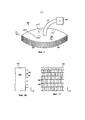
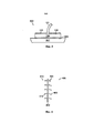
на фиг. 1А представлен схематический вид в перспективе устройства закрытия раны с созданием отрицательного давления;in fig. 1A is a schematic perspective view of a negative pressure wound closure device;
на фиг. 1В представлен вид в разрезе поверхности захватывания ткани устройства закрытия раны;in fig. 1B is a sectional view of a tissue grasping surface of a wound closure device;
на фиг. 1С представлен вид сбоку одного варианта осуществления поверхности захватывания ткани;in fig. 1C is a side view of one embodiment of a tissue gripping surface;
на фиг. 1D представлен вид сверху устройства закрытия раны, на котором представлены пунктиром стабилизаторы по осям х и у;in fig. 1D is a top view of a wound closure device showing the x and y stabilizers in dotted lines;
на фиг. 1Е представлен вид в разрезе наполнителя, на котором представлены стабилизаторы по осям х и у, а также стабилизаторы по оси z;in fig. 1E is a cross-sectional view of a filler showing x- and y-axis stabilizers and z-axis stabilizers;
на фиг. 1F представлен вид снизу устройства закрытия раны, на котором представлена гладкая нижняя поверхность и микропоры для удаления жидкости из зоны раны;in fig. 1F is a bottom view of a wound closure device showing a smooth bottom surface and micropores for removing fluid from a wound area;
на фиг. 1G представлена вертикальная проекция периферийного стабилизирующего элемента;in fig. 1G is an elevational view of a peripheral stabilizing member;
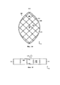
на фиг. 2А и 2В представлены вид в перспективе и вид сбоку, соответственно, опорного эндоскелета.in fig. 2A and 2B are perspective and side views, respectively, of a support endoskeleton.
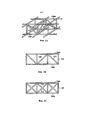
на фиг. 3А и 3В представлены вид в перспективе и вид сбоку, соответственно, опорного эндоскелета с опорными распорками;in fig. 3A and 3B are perspective and side views, respectively, of a support endoskeleton with support struts;
на фиг. 3С представлен вид сбоку опорного эндоскелета с х-образными опорными распорками;in fig. 3C is a side view of a support endoskeleton with x-shaped support struts;
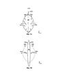
на фиг. 4А-С представлено устройство закрытия раны согласно настоящему изобретению во время закрытия раны;in fig. 4A-C show a wound closure device according to the present invention during wound closure;
на фиг. 4D-4E представлено применение нескольких элементов закрытия раны, используемых для ран разных форм;in fig. 4D-4E illustrates the application of several wound closure elements used for different wound forms;
на фиг. 5 представлено двухступенчатое устройство лечения ран с созданием отрицательного давления и закрытия раны с созданием отрицательного давления (NPWT/NPWC);in fig. 5 shows a two-stage negative pressure wound healing and negative pressure wound closure (NPWT / NPWC) device;
на фиг. 6 представлен увеличенный вид предпочтительного варианта осуществления системы фиксации ткани в соответствии с настоящим изобретением;in fig. 6 is an enlarged view of a preferred embodiment of a tissue fixation system in accordance with the present invention;
на фиг. 7 представлен вариант осуществления наполнителя раны, характеризующегося отрывной или отрезной структурой для приспособления к различным размерам раны, с фиксаторами ткани, погруженными в наполнитель в предопределенных точках разделения;in fig. 7 depicts an embodiment of a wound filler characterized by a tear-off or cut-off structure to accommodate different wound sizes, with tissue anchors immersed in the filler at predetermined separation points;
на фиг. 8А представлен вид сбоку поверхности захватывания ткани, иллюстрирующий различные фиксаторы ткани для различных типов ткани (Т1, Т2) и соответствующие профили силы для фиксаторов, включающие максимальную силу (F1), прикладываемую во время вакуумного закрытия, а также силу (F2), требуемую для удаления фиксаторов из ткани без повреждения ткани;in fig. 8A is a side view of a tissue grasping surface illustrating different tissue anchors for different tissue types (T 1 , T 2 ) and corresponding force profiles for the anchors, including the maximum force (F 1 ) applied during vacuum closure as well as the force (F 2 ) required to remove retainers from tissue without damaging the tissue;
на фиг. 8В представлены разные конструкции фиксатора ткани согласно настоящему изобретению;in fig. 8B illustrates different designs of a tissue anchor according to the present invention;
на фиг. 8С представлен увеличенный вид элементов фиксации ткани, расположенных на периферийной поверхности устройства закрытия раны овальной формы;in fig. 8C is an enlarged view of tissue fixation members located on a peripheral surface of an oval wound closure device;
на фиг. 9А представлена схематическая иллюстрация устройства закрытия раны, установленного в ране, показывающая разные профили силы вокруг границы раны в соответствии с одним вариантом осуществления;in fig. 9A is a schematic illustration of a wound closure device installed in a wound showing different force profiles around a wound margin, in accordance with one embodiment;
на фиг. 9В представлено устройство закрытия раны, представленное на фиг. 9А после периода закрытия раны и заживления, причем первоначальная конфигурация раны и устройства закрытия раны представлены пунктиром;in fig. 9B illustrates the wound closure device of FIG. 9A after a period of wound closure and healing, the initial configuration of the wound and the wound closure device being represented by a dotted line;
на фиг. 10 схематически представлен способ применения устройства закрытия раны в соответствии с настоящим изобретением.in fig. 10 is a schematic representation of a method of using a wound closure device in accordance with the present invention.
Подробное описание изобретенияDetailed description of the invention
На фиг. 1A-1F представлен вариант осуществления устройства 100 закрытия раны согласно настоящему изобретению. Устройство 100 содержит наполнитель 102 раны, который характеризуется такими размерами и формой, чтобы помещаться в отверстии раны пациента - человека или животного. Согласно предпочтительным вариантам осуществления наполнитель 102 представляет собой пористый, биологически совместимый материал, такой как полиуретановая пена с открытыми порами. Наполнитель 102 также предпочтительно обладает возможностью складывания, что подразумевает то, что его размер может быть уменьшен вдоль по меньшей мере одного направления (например, длины, ширины, высоты) посредством прикладывания отрицательного давления к наполнителю 102, в то же время, препятствуя сокращениям или сокращаясь с меньшей скоростью в другом направлении.FIG. 1A-1F show an embodiment of a
Поверхность 104 захватывания ткани проходит по меньшей мере по одной поверхности наполнителя 102, а также предпочтительно проходит по внешней периферийной поверхности наполнителя 102. Согласно одному варианту осуществления поверхность 104 захватывания ткани представляет собой эластичное покрытие, такое как ячеистая пленка, которая прикреплена к внешней периферийной поверхности наполнителя 102 и которая может растягиваться и сокращаться совместно с растяжением и сокращением наполнителя 102. Согласно одному варианту осуществления поверхность 104 захватывания ткани представляет собой ячеистую пленку или ячеистую пленку на основе сложного полиэфира, такую как сетка Parietex™, производимая компанией Covidien (Мансфилд, Массачусетс). Поверхность 104 захватывания ткани содержит множество направленных наружу элементов 106 фиксации ткани, которые согласно предпочтительному варианту осуществления представляют собой множество близкорасположенных шипов, крючков или элементов захватывания ткани, которые могут быть одним целым с ячеистой пленкой.The
На фиг. 1В представлен вид края устройства 100, на котором представлены элементы 106 захватывания ткани, выступающие из поверхности 104 захватывания ткани на периферийной поверхности наполнителя 102 раны. На фиг. 1С представлен вид сбоку одного варианта осуществления, в котором поверхность 104 захватывания ткани выполнена из эластичного материала, в частности, ячеистого материала. На фиг. 1С элементы 106 захватывания расположены перпендикулярно плоскости страницы. Эластичный ячеистый материал поверхности 104 захватывания ткани при необходимости допускает растяжение и сокращение поверхности с растяжением и сокращением нижележащего наполнителя 102 раны.FIG. 1B is an edge view of
Согласно другим вариантам осуществления поверхность 104 захватывания ткани с элементами 106 фиксации может быть одним целым с наполнителем 102. Поверхность захватывания ткани и/или элементы фиксации также могут быть выполнены с применением способного к рассасыванию материала.In other embodiments,
Элементы 106 фиксации ткани предпочтительно выполнены вдоль всей внешней периферийной поверхности наполнителя 102. Когда наполнитель 102 помещают в рану, элементы 106 фиксации оказываются погруженными в ткань на границах раны и закрепляют устройство 100 в отверстии раны. Элементы 106 фиксации ткани предпочтительно распространены вдоль всей поверхности границы раны для обеспечения достаточной величины силы захвата. Поверхность 104 захватывания ткани предпочтительно предназначена для обеспечения, как простой установки устройства 100 закрытия раны, так и простого удаления и замены новым устройством 100 или другой повязкой на рану, при необходимости (например, через 2-7 дней). Поверхность 104 захватывания может быть сконфигурирована так, чтобы характеризоваться высокой прочностью захвата, по меньшей мере, вдоль участка своей поверхности, а также характеризоваться возможностью беспрепятственного удаления, например, путем оттягивания за край. Поверхность 104 захватывания ткани предпочтительно предназначена для удаления из раны без повреждения окружающей ткани. Элементы 106 фиксации предпочтительно предназначены для обеспечения возможности применения с различными тканями, такими как мышечная ткань, жировая ткань, кожа, коллаген и их различные сочетания. Элементы 106 фиксации также могут быть предназначены для того, чтобы оставаться надежно прикрепленными к определенным тканям в течение выбранного периода времени согласно определенным вариантам осуществления.
Согласно некоторым вариантам осуществления, в которых поверхность 104 захватывания образована покрытием, расположенным на внешней периферийной поверхности наполнителя 102, поверхность захватывания может быть прикреплена к наполнителю 102 с применением любого подходящего способа, например, при помощи системы с механическим креплением или креплением клеем. Согласно предпочтительному варианту осуществления поверхность 104 захватывания ткани содержит захватывающие наполнитель элементы фиксации, которые могут представлять собой шипы, которые прикрепляют поверхность захватывания к наполнителю. Как, например, представлено на виде в разрезе, представленном на фиг. 6, поверхность 400 захватывания содержит тонкую сетку или пленку, содержащую два ряда шипов или подобных элементов фиксации - первый ряд 410 направленных наружу элементов 412 захватывания ткани, предназначенных для прохождения в ткань, и второй ряд 404 элементов 406, которые проходят в наполнитель для прикрепления поверхности захватывания к наполнителю.In some embodiments, in which the
Вернемся к фигурам 1A-1F, источник 120 отрицательного давления, например, насос, подключен к наполнителю 102 посредством подходящего соединения или трубопровода, такого как трубка 121. Дополнительные трубки 107 также могут быть подключены через группу разнесенных отверстий 105 для пространственного распределения всасывающей силы таким образом, чтобы силой, действующей вдоль боковой стенки 104, можно было управлять отдельно от силы всасывания жидкости. Источник 120 отрицательного давления может быть активирован для приложения отрицательного давления к наполнителю 102. В целом, отрицательное давление вызывает результирующий перепад давления, который вызывает сокращение или «сжатие» наполнителя 102. Когда наполнитель 102 сокращается, поверхность 104 захватывания ткани захватывает и тянет к себе смежную ткань, которая предпочтительно представляет собой ткань около границы раны, вызывая перемещение ткани, что, тем самым, способствует закрытию раны. Согласно предпочтительному варианту осуществления наполнитель 102 рассчитан на то, чтобы сжиматься предпочтительно по меньшей мере в одном направлении. Например, согласно варианту осуществления, который представлен на фиг. 1А, наполнитель 102 характеризуется длиной и шириной вдоль осей у и х, соответственно, а также высотой вдоль оси z. Для того чтобы эффективно передавать отрицательное давление к подкожным или другим границам раны, предпочтительно, чтобы наполнитель 102 не сжимался по центру в направлении z (подобно лепешке), так чтобы отрицательное давление действовало преимущественно в направлениях х-у, или более конкретно, в двумерной плоскости вдоль границ раны, как при открытой брюшной полости или фасциотомии. Следует понимать, что согласно некоторым вариантам осуществления плоскость границ раны может быть изогнутой, например, когда рана проходит по изгибу брюшной полости или ноги.Returning to Figures 1A-1F, a
Кроме того, согласно предпочтительным вариантам осуществления наполнитель 102 сконфигурирован таким образом, чтобы предпочтительно сжиматься в длину и/или в ширину (т.е., вдоль осей х и у) для повторного сближения ткани на границах раны. Следует обратить внимание, что определенные типы ран можно лечить без элементов фиксации, описанных в настоящем документе.In addition, in preferred embodiments, the
Существует несколько способов, в которых наполнитель 102 сконфигурирован таким образом, чтобы демонстрировать предпочтительные характеристики сжатия. Например, некоторые участки наполнителя 102 могут быть выполнены из более жесткого материала, чем окружающий материал, вызывая сжатие наполнителя предпочтительно в определенном направлении. Согласно одному варианту осуществления наполнитель 102 может содержать стабилизирующий эндоскелет, выполненный из подходящего жесткого материала, погруженного в «сжимающийся» наполнитель, такой как пена с открытыми порами. Следует отметить, что величина прикладываемого отрицательного давления может быть отрегулирована в зависимости от размера и формы раны. Значения давления, составляющие от 125 мм до 250 мм или более, могут быть применены для содействия в закрытии раны. Давление может быть уменьшено со временем, когда рана сократится.There are several ways in which the
Как, например, показано на фиг. 1D и 1Е, наполнитель 102 содержит множество стабилизирующих элементов 108 (показаны пунктиром), которые допускают сжатие наполнителя в определенных направлениях, а также препятствуют ему в других направлениях. Согласно этому варианту осуществления стабилизирующие элементы 108 содержат множество стабилизирующих ребер, изогнутых деталей или стержней, выполненных из подходящего жесткого или полужесткого материала, такого как пластмасса. Ребристая структура сконфигурирована для сжатия предпочтительно вдоль определенной оси таким образом, чтобы способствовать правильному закрытию раны. Внутренние стабилизирующие элементы 108 согласно этому варианту осуществления образуют решетчатую структуру, как видно на фиг. 1D, однако следует понимать, что могут быть применены другие конфигурации. Например, расстояние между элементами в «открытом» состоянии может находиться в пределах 1-2 см. Стабилизирующие элементы 108 могут быть установлены на разных глубинах в наполнителе, как показано на виде в разрезе, представленном на фиг. 1Е, что помогает препятствовать сжатию в направлении z. Согласно некоторым вариантам осуществления стабилизирующие по оси z элементы 110 могут быть применены для препятствования сжатию в этом направлении. На фиг. 1Е стабилизирующие по оси z элементы 110 представляют собой выступы, проходящие в вертикальном направлении от ребер 108. Согласно другим вариантам осуществления могут быть применены отдельные стабилизаторы по оси z, такие как структуры в виде стержней или ребер.As shown in FIG. 1D and 1E, the
Согласно определенным вариантам осуществления устройство 100 может содержать периферийный стабилизирующий элемент 111, проходящий вокруг внешней периферийной поверхности наполнителя 102, как показано на фиг. 1Е. Стабилизирующий элемент 111 может содержать структуру в виде ребер, которая усиливает наполнитель 102 для предотвращения сжатия в направлении z, а также препятствования наклону наполнителя в плоскостях z-y и z-x. Таким образом, согласно предпочтительным вариантам осуществления сокращение наполнителя предпочтительно происходит по меньшей мере в первом направлении относительно второго направления при приложении отрицательного давления. Таким образом, например, ширина будет сокращаться с большей скоростью относительно длины, при этом не будет происходить существенного сокращения высоты (глубина раны).In certain embodiments, the
Согласно некоторым вариантам осуществления захватывающие ткань элементы 106 фиксации могут быть выполнены на периферийном стабилизирующем элементе 111, и выступать из периферийной поверхности наполнителя 102. Это может быть альтернативой, или дополнением к выполнению элементов 106 фиксации на отдельной сетке или пленке. Периферийный стабилизирующий элемент 111 предпочтительно сконфигурирован так, чтобы при необходимости растягиваться и сокращаться совместно с растяжением и сокращением наполнителя 102 раны. Таким образом, согласно предпочтительному варианту осуществления стабилизирующий элемент 111 характеризуется достаточной эластичностью для сокращения и растяжения в направлениях х и у (т.е., вокруг периферийной поверхности наполнителя 102), а также характеризуется отвечающем требованиям значением жесткости вдоль направления z (т.е. вдоль высоты наполнителя) для препятствования сжатию или наклону в этом направлении.In some embodiments, tissue gripping
На фиг. 1G представлена вертикальная проекция варианта осуществления периферийного стабилизирующего элемента 111. Стабилизирующий элемент 111 содержит несколько стабилизирующих стержней 113, направленных так, чтобы препятствовать сжатию в направлении z. Стержни 113 разделены эластичным материалом 114, что позволяет стабилизирующему элементу 111 растягиваться и сокращаться вокруг границы раны совместно с растяжением и сокращением нижележащего наполнителя. Согласно этому варианту осуществления элементы 106 фиксации ткани сформированы в периферийном стабилизирующем элементе 111 и расположены перпендикулярно плоскости страницы.FIG. 1G is an elevational view of an embodiment of the peripheral stabilizing
Один вариант осуществления эндоскелета для наполнителя раны согласно настоящему изобретению показан на фиг. 2А и 2В. Эндоскелет содержит первый ряд стабилизирующих по осям х и у элементов 108а, а также второй ряд стабилизирующих по осям х и у элементов 108b, которые соединены при помощи множества стабилизирующих по оси z элементов 110. Во время сжатия наполнителя 102 соответствующие стабилизирующие по осям х и у элементы 108а, 108b могут быть сжаты в направлениях х- у, однако стабилизирующие по оси z элементы 110 препятствуют сжатию в направлении z. Согласно предпочтительным вариантам осуществления стабилизирующие элементы могут быть повернуты по отношению друг к другу во время сжатия. Сочленения 109 в указанной конструкции могут быть шарнирными или характеризоваться уменьшенной толщиной для того, чтобы обеспечивать гибкость системы. В гибких местах между сочленениями также может произойти изгиб для обеспечения желаемого сжатия вдоль первой, или поперечной, оси 117 (см. фиг. 4В). Некоторое растяжение может возникать вдоль второй, или продольной, оси 119 при сжатии устройства. Материал каркаса может характеризоваться свойством памяти формы, что в сочетании с всасывающей силой, определяет уровень силы, прикладываемой к ткани.One embodiment of a wound filler endoskeleton according to the present invention is shown in FIG. 2A and 2B. The endoskeleton contains a first row of x- and y-stabilizing
Согласно другому варианту осуществления, показанному на фиг. 3А и 3В, эндоскелет содержит стабилизаторы 112 в виде распорок для препятствования наклону наполнителя 102 во время сжатия. Стабилизаторы 112 в виде распорок удерживают верхние 108а и нижние 108b стабилизаторы по осям х и у выровненными относительно друг друга при сжатии наполнителя 102. Согласно некоторым вариантам осуществления стабилизаторы 112 в виде распорок могут быть жесткими в определенных направлениях и относительно менее жесткими в других направлениях (например, стабилизатор в виде распорки может быть изогнутым) для способствования сжатию в определенных направлениях. На фиг. 3С представлен альтернативный вариант осуществления, содержащий стабилизаторы 112 в виде распорок в «х»-образной конфигурации.In another embodiment, shown in FIG. 3A and 3B, the endoskeleton includes
Стабилизирующий эндоскелет согласно определенным вариантам осуществления может быть выполнен целиком или частично из материала с памятью формы. Могут быть использованы различные материалы с памятью формы, которые возвращаются из деформированного состояния (временная форма) в свою первоначальную (постоянную) форму. Это изменение формы может быть вызвано внешним воздействием или пусковым механизмом. Согласно одному варианту осуществления первоначальная или «постоянная» форма эндоскелета представляет собой «сжатую» конфигурацию устройства закрытия раны, или форму, которая приведет к закрытию краев раны. Когда устройство закрытия раны в исходном положении вставлено в отверстие раны, эндоскелет пребывает в деформированном или временном состоянии, а также заключен в наполнителе. Эндоскелет может предпочтительно возвращаться в свое первоначальное или «сжатое» состояние или, в качестве альтернативы, вызывать расширение устройства для того, чтобы захватить ткань. Сила «сжатия» эндоскелета с памятью формы может являться дополнением или альтернативой силе разрежения, создаваемой источником отрицательного давления. Согласно определенным вариантам осуществления к устройству закрытия раны прикладывают отрицательное давление, что может вызывать возвращение эндоскелета в его первоначальное состояние.The stabilizing endoskeleton, according to certain embodiments, may be made in whole or in part from a shape memory material. Various shape memory materials can be used that return from a deformed state (temporary shape) to their original (permanent) shape. This change in shape can be caused by an external force or a trigger. In one embodiment, the initial or "permanent" shape of the endoskeleton is a "compressed" configuration of the wound closure device, or a shape that will close the edges of the wound. When the wound closure device is initially inserted into the wound opening, the endoskeleton is in a deformed or temporary state and is also enclosed in a filler. The endoskeleton may preferably return to its original or "collapsed" state, or, alternatively, cause the device to expand in order to capture tissue. The “compression” force of a shape memory endoskeleton can be a complement or alternative to the rarefaction force generated by a negative pressure source. In certain embodiments, negative pressure is applied to the wound closure device, which can cause the endoskeleton to return to its original state.
На фиг. 1F представлена нижняя часть устройства 100 закрытия раны согласно одному варианту осуществления. Устройство 100 согласно этому варианту осуществления содержит гладкую нижнюю поверхность 115. Этот материал может представлять собой биологически совместимую пленку, предназначенную для применения с системой Renasys®, доступной от компании Smith & Nephew, например, пленку поставляемую с указанной системой. Предпочтительный вариант осуществления также может быть применен с вакуумным манометром, который также предусмотрен в системе Renasys®. Нижняя поверхность 115 обеспечивает границу контакта с низким коэффициентом трения между устройством 100 закрытия раны и нижележащей тканью. В случае раны в брюшной полости, например, нижележащая ткань может содержать внутренние органы, такие как кишки. Гладкая нижняя поверхность 115 позволяет наполнителю 102 свободно сокращаться и растягиваться без помех со стороны нижележащей ткани, а также без повреждения нижележащей ткани. Согласно предпочтительному варианту осуществления нижняя поверхность 115 содержит микропоры 116 (показанные на фиг. 1F увеличенными в целях иллюстрации), допускающие прохождение жидкости через нижнюю поверхность 115 и далее в устройство 100 для удаления из зоны раны. Устройство закрытия раны может также быть вставлено поверх отдельного слоя материала, в результате чего сокращение устройства будет происходить сверху скользящего слоя.FIG. 1F illustrates the bottom of a
Согласно некоторым вариантам осуществления микропоры 116 могут характеризоваться различными размерами в различных областях и/или могут характеризоваться различными значениями плотности пор в различных областях для прикладывания различных уровней силы, создаваемой источником вакуума, к разным областям устройства 100. Аналогично, наполнитель 102 может быть разработан с различными внутренними размерами пор и/или значениями плотности пор для направления распределения сил от источника вакуума к различным областям устройства 100.In some embodiments,
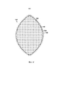
На фиг. 4А-4С представлено применение настоящего устройства 100 для закрытия раны 200. Как показано на фиг. 4А, рана 200 содержит отверстие 201 раны и границу 203 раны. На фиг. 4В устройство 100 закрытия раны помещено в отверстие 201 раны, в результате чего поверхность 104 захватывания ткани взаимодействует с границей 203 раны. Согласно определенным вариантам осуществления устройство 100 закрытия раны может быть сформировано путем уменьшения размера наполнителя 102 до подходящего значения при помощи отрезания или отрывания, а затем прикрепления элементов 106 захватывания ткани вокруг периферийной поверхности наполнителя 102. Согласно одному варианту осуществления элементы 106 захватывания присоединяют посредством прикрепления содержащей с двух сторон шипы сетки к наполнителю 102, причем направленные наружу зубцы предназначены для захватывания ткани, а направленные вовнутрь зубцы предназначены для прикрепления сетки к наполнителю 102. Трубка 121 присоединяет наполнитель 102 к источнику отрицательного давления. Область раны 200, включая наполнитель 102, может быть покрыта уплотняющей салфеткой 205.FIG. 4A-4C illustrate the use of the
Согласно варианту осуществления на фиг. 4В наполнитель 102 содержит множество внутренних стабилизирующих элементов 108 (показаны пунктиром), благодаря которым наполнителю 102 присуща предпочтительная характеристика сжатия. Стабилизирующие элементы 108 помогают управлять сжатием наполнителя 102 и результирующим перемещением ткани вокруг границы 203 раны в направлениях х и у. Дополнительные стабилизирующие элементы могут быть обеспечены для управления или препятствования сжатию вдоль направления z. Как описано выше применительно к фиг. 1D, стабилизирующие элементы 108 согласно этому варианту осуществления характеризуются решетчатой конфигурацией.In the embodiment of FIG. 4B, the
На фиг. 4С представлена рана 200 после приложения отрицательного давления к устройству 100 закрытия раны. Элементы 106 фиксации ткани захватывают границы 203 ткани и вызывают перемещение границ 203 ткани при сжатии наполнителя 102. Как видно на фиг. 4С, наполнитель 102 сжимается в направлениях х и у таким образом, чтобы сблизить ткань на границе 203 раны. Согласно варианту осуществления на фиг. 4В и 4С решетчатая конфигурация стабилизирующих элементов 108 помогает управлять направлением перемещения ткани во время сжатия. Наибольшее перемещение ткани согласно этому варианту осуществления происходит в центральной области раны 200, где отверстие 201 характеризуется наибольшей шириной, причем указанное перемещение главным образом направлено вовнутрь вдоль направления х. За пределами центральной области (например, в верхней части и нижней части раны, как показано на фиг. 4А и 4В), где границы раны находятся близко друг к другу, требуется меньшее перемещение в направлении х для того, чтобы сблизить ткань. Как правило, направленное вовнутрь сжатие наполнителя вдоль направления у является нежелательным. Фактически, во время сближения ткани, рана 200 будет стремиться к удлинению в направлении у, по мере того как границы раны сближаются в направлении х. Согласно предпочтительным вариантам осуществления внутренние стабилизирующие элементы 108 способствуют сжатию наполнителя таким образом, чтобы обеспечить сближение ткани раны. Согласно варианту осуществления, представленному на фиг. 4В-С, например, во время сжатия наполнителя скрещенные стабилизирующие элементы 108 выпрямляются относительно друг друга, подобно вертикально-складным воротам. Наибольшее перемещение присутствует в центральной области наполнителя 102, вдоль направления х. Как правило, стабилизаторы 108 препятствуют направленному вовнутрь сжатию вдоль направления у. При выпрямлении стабилизаторов 108, они могут также способствовать удлинению раны в направлении у для обеспечения правильного сближения ткани раны. На фиг. 4D-4E показаны раны 220, 240 различных форм, причем несколько элементов закрытия раны применяют одновременно с тем, чтобы выполнить заполнение раны. На фиг. 4D элементы 222, 224, 226 и 228 характеризуются различными формами, которые обрезаны или подрезаны до таких размеров, которые позволяют по существу заполнить рану, которая в этом примере характеризуется округлой формой. При приложении отрицательного давления элементы работают вместе для того, чтобы закрыть рану в желаемом направлении. На фиг. 4Е представлена прямоугольная рана 240, для заполнения которой применяют закрывающие элементы 242, 244, 246, 248 и 250. Фиксаторы ткани каждого закрывающего элемента могут также быть прикреплены к соседнему закрывающему элементу (элементам). Благодаря разрежению, прикладываемому к центральным элементам 224, 250, происходит притягивание соседних элементов к центральным элементам для того, чтобы закрыть рану.FIG. 4C shows a
Устройство закрытия раны 200 может оставаться в такой конфигурации в течение нескольких дней или недель для способствования закрытию и заживлению раны 200. После периода заживления устройство 100 может быть удалено и факультативно заменено меньшим устройством. После того как рана была успешно закрыта при помощи настоящего устройства, она может быть закрыта посредством наложения шва.The
На фиг. 5 представлено двухступенчатое устройство 300 лечения ран с созданием отрицательного давления и закрытия раны с созданием отрицательного давления (NPWT/NPWC). Устройство содержит компонент 301 дренирования/управления жидкостью с созданием отрицательного давления, известный из уровня техники, который соединен с расположенным выше устройством 100 закрытия раны с созданием отрицательного давления. Устройство 100 закрытия раны содержит сжимающийся наполнитель 102 раны и поверхность 104 захватывания ткани, по существу как описано выше. Трубка 121 соединяет устройство 300 с одним насосом для прикладывания отрицательного давления к компонентам для закрытия раны и лечения раны. Устройство 300 может содержать взаимозаменяемые детали, использование которых зависит от типа определенной раны. Согласно одному варианту осуществления устройство 300 применяют для ран в брюшной полости, а также может быть применено для ран средостения и при фасциотомии.FIG. 5 shows a two-stage negative pressure wound treatment and negative pressure wound closure (NPWT / NPWC) device. The device comprises a negative pressure drainage /
Согласно предпочтительному варианту осуществления наполнитель 102 выполнен с возможностью «скольжения» внутри устройства 300 NPWT/NPWC в сборе. Наполнитель 102 содержит поверхность 303 скольжения на границе контакта между компонентами закрытия раны и управления жидкостью. Поверхность скольжения может содержать обработанную поверхность или отдельный слой материала. Поверхность 303 скольжения облегчает свободное сокращение компонента закрытия раны без помехи со стороны компонента управления жидкостью. Расположенный ниже компонент 301 управления жидкостью может быть определенным образом сконфигурирован для того, чтобы лишь осуществлять управление жидкостью и не создавать образование гранул, так как это может замедлять «скольжение» или препятствовать ему.In a preferred embodiment, the
На фиг. 6 представлен увеличенный вид предпочтительного варианта осуществления системы 400 фиксации ткани в соответствии с настоящим изобретением. Одна сторона материала 402 содержит первую группу элементов 404 фиксации, которые предназначены для захвата наполнителя. Первые элементы 404 фиксации могут быть сформированы для захвата наполнителя, например, они могут характеризоваться проходящей в дистальном направлении крючкообразной формой 406. Поскольку материал 402 должен быть прикреплен к наполнителю с определенной прочностью захвата для того, чтобы приложить достаточное тянущее усилие к ткани, для удаления крючков из наполнителя должен быть приложен определенный уровень силы F, который превышает тянущее усилие, прикладываемое к ткани. Аналогично, поскольку ткань, которую необходимо захватить с помощью материала 402, характеризуется отличными от наполнителя структурными характеристиками, вторая группа элементов 410 фиксации, предназначенных для захвата ткани, может характеризоваться формой и силой захвата, отличными от формы и силы захвата первых элементов фиксации. Согласно этому варианту осуществления шипы 412 будут двусторонними зубцами 414, которые характеризуются свойством сжиматься при введении в ткань, и расширяться при вытягивании в противоположном направлении, в результате чего к ткани может быть приложено определенное тянущее усилие. Тем не менее, зубцы или элементы фиксации конической формы характеризуются усилием отпускания, в результате чего шипы могут быть вручную извлечены из ткани без нанесения повреждения.FIG. 6 is an enlarged view of a preferred embodiment of a
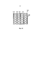
На фиг. 7 представлен вариант осуществления материала 500 наполнителя раны, характеризующийся отрывной или отрезной структурой для приспособления к различным размерам раны. Материал 500 наполнителя содержит естественные линии 501, 503, 505 разделения, которые позволяют скорректировать размер материала для помещения в рану, подлежащую закрытию. Материал 500 спроектирован с возможностью отрывания или отрезания по линиям разделения для удаления одного или нескольких участков 502а, 502b, 502с материала и корректировки размера материала. Ряды фиксаторов 506а, 506b, 506с, 506d ткани погружены в наполнитель в предварительно определенных точках разделения, и становятся доступными при удалении соответствующих внешних участков 502а, 502b, 502с. Фиксаторы 506а, 506b, 506с, 506d ткани могут быть связаны со структурой стабилизирующего эндоскелета, так как описано выше применительно к фигурам 1-4. Согласно некоторым вариантам осуществления структура стабилизирующего эндоскелета может содержать предварительно определенные точки разделения для удаления участков стабилизирующей структуры в случае корректировки размера материала 500 наполнителя.FIG. 7 depicts an embodiment of a
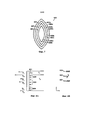
На фиг. 8А представлен вид сбоку поверхности захватывания ткани, иллюстрирующий разные фиксаторы 601, 602, 603, 604 ткани, предназначенные для разных типов ткани (Т1, Т2). Кроме того, представлен пример соответствующих профилей силы для фиксаторов, включающих максимальную силу (F1), прикладываемую к ткани во время вакуумного закрытия, и силу (F2), необходимую для удаления фиксаторов из ткани без повреждения ткани. Согласно одному варианту осуществления характеристики фиксаторов ткани отличаются для обеспечения разных профилей силы по границе контакта между устройством закрытия раны и окружающей тканью. Например, для верхнего слоя (слоев) Т ткани, фиксатор 601 сконструирован для прикрепления к коллагеновому материалу, такому как в дерме. Фиксатор 601 характеризуется отличным профилем силы (F1 и F2) в верхнем слое (слоях) Т1 ткани, как показано на фиг. 8А. В нижних слоях Т2 ткани, фиксаторы 602, 603, 604 сконструированы для прикрепления к жировой ткани подкожного слоя. Как правило, для прикрепления фиксаторов к этой ткани требуется меньший профиль силы.FIG. 8A is a side view of a tissue gripping surface illustrating different tissue anchors 601, 602, 603, 604 for different tissue types (T 1 , T 2 ). In addition, an example of appropriate force profiles for anchors is provided, including the maximum force (F 1 ) applied to the tissue during vacuum closure and the force (F 2 ) required to remove the anchors from the tissue without damaging the tissue. In one embodiment, the characteristics of the tissue anchors are different to provide different force profiles at the interface between the wound closure device and surrounding tissue. For example, for the top layer (s) of T tissue,
Характеристики фиксаторов и их результирующие профили силы могут отличаться некоторым количеством параметров, например, значением длины фиксатора, формой фиксатора, конструкцией захватывающих частей, материалом (материалами), применяемым для изготовления фиксатора, относительной эластичностью/жесткостью фиксаторов и шагом/плотностью фиксаторов. На фиг. 8А, например, фиксатор 601 существенно длиннее фиксаторов 602, 603, которые в свою очередь длиннее фиксаторов 604. На фиг. 8А также представлено изменение плотности фиксаторов на примере фиксаторов 602, 603 и 604. На фиг. 8В представлено три примера разных типов захватывающих частей, включающих конфигурацию 605 с шипами, конфигурацию 606 со смещенными крючками, и конфигурацию 607 со смешенными шипами. Другие подходящие захватывающие части могут быть применены подобно элементам 620 фиксации, показанным в увеличенном виде в перспективе, представленном на фиг. 8С. Процесс зацепления может быть дополнен пришиванием наполнителя или опорного эндоскелета к ткани. Профиль силы может быть изменен посредством управления распределением силы разрежения в наполнителе, например, посредством изменения размера пор и/или плотности пор наполнителя.The characteristics of anchors and their resulting force profiles can differ in a number of parameters, for example, the length of the anchor, the shape of the anchor, the design of the gripping parts, the material (s) used to make the anchor, the relative elasticity / stiffness of the anchors, and the pitch / tightness of the anchors. FIG. 8A, for example,
Устройство закрытия раны согласно настоящему изобретению может быть предоставлено в наборах для закрытия разных типов ран (например, раны в брюшной полости, раны при фасциотомии и т.п.). Поверхность захватывания ткани может быть оптимизирована для разных типов ткани, такой как коллаген, жировая ткань и мышцы, в зависимости от структуры ткани в зоне раны.The wound closure device of the present invention may be provided in kits for closing various types of wounds (eg, abdominal wounds, fasciotomy wounds, and the like). The tissue grasping surface can be optimized for different tissue types such as collagen, adipose tissue and muscle, depending on the tissue structure in the wound area.
Согласно определенным вариантам осуществления профиль силы устройства закрытия раны изменяется по периферийной поверхности раны. Примерный вариант осуществления представлен на фиг. 9А, на которой показан профиль силы (f1), приложенной к границам раны во множестве мест на периферийной поверхности раны. Согласно этому варианту осуществления наибольшая сила f1 действует в центральной области наполнителя 102 раны, где отверстие раны характеризуется наибольшей шириной, и сила закрытия раны полностью или практически полностью действует в направлении х. Закрывающая сила (f1) значительно уменьшается при перемещении в направлении верхней и нижней областей раны. Одной причиной для этого является то, что отверстие раны намного меньше в этих областях, и намного меньшая сила требуется для сближения краев ткани. Кроме того, направленная вовнутрь сила, приложенная в этих областях, содержит компоненты в обоих направлениях х и у. Таким образом, профиль меньшей силы предпочтителен для того, чтобы избежать направленного вовнутрь сжатия ткани в направлении у. Как представлено на фиг. 9В, по мере закрытия и заживления раны от первоначального состояния (показанного пунктирными линиями) до более позднего состояния (показанного сплошными линиями), она становится удлиненной в направлении у. Таким образом, перемещение фиксаторов 701а и 701 b ткани происходит исключительно в направлении х и в направлении закрывающей силы (f1), тогда как перемещение фиксаторов 703а, 703b ткани происходит как вовнутрь в направлении х (в направлении закрывающей силы), так и наружу в направлении у (противоположном направлению закрывающей силы). Таким образом, меньшая f1 предпочтительна в этих областях для обеспечения большего «свободного хода» между элементами фиксации и окружающей тканью. Альтернативно, устройство закрытия раны сконфигурировано так, что оно не удлиняется, т.е. не изменяет свою длину вдоль продольной оси 720.In certain embodiments, the force profile of the wound closure device changes along the peripheral surface of the wound. An exemplary embodiment is shown in FIG. 9A, which shows the profile of the force (f 1 ) applied to the wound margins at multiple locations on the peripheral surface of the wound. In this embodiment, the greatest force f 1 acts in the central region of the
Изменение профиля силы вокруг периферийной поверхности устройства закрытия раны может быть достигнуто различными способами, такими как изменение шага/плотности фиксаторов ткани, типов фиксаторов, длины фиксаторов и т.п. Например, на фиг. 9А и 9В фиксаторы 701а, 701b длиннее и проникают в ткань глубже по сравнению с фиксаторами 703а, 703b. Профиль силы может также изменяться посредством управления распределением силы разрежения в наполнителе, например, посредством изменения размера пор и/или плотности пор наполнителя.Changing the force profile around the peripheral surface of the wound closure device can be achieved in various ways, such as changing the pitch / density of tissue anchors, types of anchors, length of anchors, and the like. For example, in FIG. 9A and 9B, anchors 701a, 701b are longer and penetrate deeper into tissue than
Согласно одному варианту осуществления способ изготовления устройства закрытия раны согласно настоящему изобретению включает формирование стабилизирующего эндоскелета из жесткого или полужесткого материала и формирование сжимающегося наполнителя поверх эндоскелета. Стабилизирующий эндоскелет может быть сформирован с применением процесса литья и может быть отлит в виде единого структурного элемента или одного или нескольких компонентов, которые затем собирают для формирования эндоскелета. Разные компоненты эндоскелета могут характеризоваться разной толщиной и/или степенью жесткости для обеспечения различающихся уровней жесткости и эластичности вдоль разных направлений. Эндоскелет может быть собран посредством соединения компонентов, например, посредством применения подходящего процесса склеивания или другого процесса соединения. Согласно определенным вариантам осуществления, по меньшей мере, некоторые компоненты могут быть собраны так, чтобы обеспечивать шарнирные соединения. Согласно предпочтительным вариантам осуществления наполнитель сформирован посредством смешивания подходящим образом дозированных количеств составных веществ, (например, изоцианатов, полиолов, катализаторов, поверхностно- активных веществ, вспенивающих веществ и т.п. в случае полиуретановой пены), дозирования реагирующей смеси в форму, а затем отверждения материала и извлечения его из формы. Факультативно, затем материал может быть обрезан или подрезан до окончательной формы. Согласно предпочтительным вариантам осуществления опорную структуру эндоскелета собирают и помещают в форму, а наполнитель заливают вокруг эндоскелета. В опубликованной заявке на патент США No 2009/0093550, Rolfes at al., содержание которой полностью включено в состав настоящего документа посредством ссылки, раскрыт пример продукта в виде биоразлагаемой пены, подходящей для настоящего устройства закрытия раны, а также способы изготовления такой пены.In one embodiment, a method of making a wound closure device according to the present invention comprises forming a stabilizing endoskeleton from a rigid or semi-rigid material and forming a collapsible filler over the endoskeleton. The stabilizing endoskeleton can be formed using a casting process and can be cast as a single structural unit or one or more components that are then assembled to form the endoskeleton. Different components of the endoskeleton can have different thicknesses and / or degrees of rigidity to provide different levels of rigidity and elasticity along different directions. The endoskeleton can be assembled by joining components together, for example, using a suitable bonding process or other bonding process. In certain embodiments, at least some of the components may be assembled to provide pivot connections. In preferred embodiments, the filler is formed by mixing suitably metered amounts of constituents (e.g., isocyanates, polyols, catalysts, surfactants, blowing agents, and the like in the case of polyurethane foam), metering the reactant mixture into a mold, and then curing the material and removing it from the mold. Optionally, the material can then be trimmed or trimmed to its final shape. In preferred embodiments, the endoskeleton support structure is assembled and placed in a mold and filler is poured around the endoskeleton. US Published Patent Application No. 2009/0093550, Rolfes et al., The entire contents of which are incorporated herein by reference, discloses an example of a biodegradable foam product suitable for the present wound closure device, as well as methods for making such foam.
Способ выполнения хирургической операции 800 с применением устройства закрытия раны согласно предпочтительным вариантам осуществления изобретения представлен на фиг. 10. После подготовки 810 пациента к операции, выполняют 820 разрез для открытия операционного поля, обычно в брюшной полости. После выполнения операции, рану подготавливают 830 к закрытию. Выбирают 840 подходящий размер и форму устройства закрытия раны с периферическими элементами прикрепления к ткани, расположенными по периметру или на внешней поверхности стенки устройства. Устройство помещают 850 в рану и элементы прикрепления к ткани помещают 860 в ткань. Затем прикладывают 870 отрицательное давление для того, чтобы приложить закрывающую силу к краям раны. В зависимости от частного применения, для больших ран может требоваться расположение 880 меньшего второго устройства закрытия после удаления первого большего устройства. Наконец, устройство удаляют 890 и рану закрывают, как правило, посредством наложения шва.A method of performing
Несмотря на то, что настоящее изобретение было описано применительно к конкретным способам и устройству, специалистам в данной области техники должны быть очевидны другие эквиваленты конкретным вариантам осуществления, раскрытым в настоящем документе. Следует иметь в виду, что описание приведено в качестве примера, а не в целях ограничения объема настоящего изобретения, и указанные эквиваленты охватываются изложенной ниже формулой изобретения.Although the present invention has been described with reference to specific methods and apparatus, other equivalents to the specific embodiments disclosed herein will be apparent to those skilled in the art. It should be borne in mind that the description is given by way of example, and not to limit the scope of the present invention, and these equivalents are covered by the following claims.
Claims (77)
Applications Claiming Priority (2)
| Application Number | Priority Date | Filing Date | Title |
|---|---|---|---|
| US201161439525P | 2011-02-04 | 2011-02-04 | |
| US61/439,525 | 2011-02-04 |
Related Parent Applications (1)
| Application Number | Title | Priority Date | Filing Date |
|---|---|---|---|
| RU2013140635A Division RU2612529C2 (en) | 2011-02-04 | 2012-02-03 | Wound closing device creating negative pressure |
Publications (3)
| Publication Number | Publication Date |
|---|---|
| RU2017106796A RU2017106796A (en) | 2019-01-21 |
| RU2017106796A3 RU2017106796A3 (en) | 2020-06-03 |
| RU2756986C2 true RU2756986C2 (en) | 2021-10-08 |
Family
ID=46603322
Family Applications (2)
| Application Number | Title | Priority Date | Filing Date |
|---|---|---|---|
| RU2017106796A RU2756986C2 (en) | 2011-02-04 | 2012-02-03 | Wound closure device with the creation of negative pressure |
| RU2013140635A RU2612529C2 (en) | 2011-02-04 | 2012-02-03 | Wound closing device creating negative pressure |
Family Applications After (1)
| Application Number | Title | Priority Date | Filing Date |
|---|---|---|---|
| RU2013140635A RU2612529C2 (en) | 2011-02-04 | 2012-02-03 | Wound closing device creating negative pressure |
Country Status (10)
| Country | Link |
|---|---|
| US (4) | US9226737B2 (en) |
| EP (2) | EP2670312B1 (en) |
| JP (4) | JP6158096B2 (en) |
| CN (2) | CN103501709B (en) |
| AU (5) | AU2012212070A1 (en) |
| CA (1) | CA2828964A1 (en) |
| MX (2) | MX358022B (en) |
| RU (2) | RU2756986C2 (en) |
| WO (1) | WO2012106590A2 (en) |
| ZA (1) | ZA201306619B (en) |
Families Citing this family (76)
| Publication number | Priority date | Publication date | Assignee | Title |
|---|---|---|---|---|
| US11298453B2 (en) | 2003-10-28 | 2022-04-12 | Smith & Nephew Plc | Apparatus and method for wound cleansing with actives |
| US10413644B2 (en) | 2004-04-27 | 2019-09-17 | Smith & Nephew Plc | Wound treatment apparatus and method |
| US8529548B2 (en) | 2004-04-27 | 2013-09-10 | Smith & Nephew Plc | Wound treatment apparatus and method |
| US9820888B2 (en) | 2006-09-26 | 2017-11-21 | Smith & Nephew, Inc. | Wound dressing |
| GB0808376D0 (en) | 2008-05-08 | 2008-06-18 | Bristol Myers Squibb Co | Wound dressing |
| GB0817796D0 (en) | 2008-09-29 | 2008-11-05 | Convatec Inc | wound dressing |
| GB201020236D0 (en) | 2010-11-30 | 2011-01-12 | Convatec Technologies Inc | A composition for detecting biofilms on viable tissues |
| CN103347561B (en) | 2010-12-08 | 2016-09-07 | 康沃特克科技公司 | For assessing the integrated system of wound exudate |
| EP2648794B1 (en) | 2010-12-08 | 2019-08-28 | ConvaTec Technologies Inc. | Wound exudate system accessory |
| US9421132B2 (en) | 2011-02-04 | 2016-08-23 | University Of Massachusetts | Negative pressure wound closure device |
| RU2756986C2 (en) | 2011-02-04 | 2021-10-08 | Юниверсити Оф Массачусетс | Wound closure device with the creation of negative pressure |
| RU2611760C2 (en) | 2011-06-07 | 2017-02-28 | Смит Энд Нефью Плс | Wound contacting elements and methods of their use |
| CN103702710B (en) * | 2011-07-19 | 2016-06-29 | 心脏防护医疗技术公司 | Regulator in negative pressure wound therapy, the shaping piece including regulator and wound dressing, for control the position of wound dressing or shaping piece method and for promote from wound dressing or the method for shaping piece drain |
| GB201115182D0 (en) | 2011-09-02 | 2011-10-19 | Trio Healthcare Ltd | Skin contact material |
| GB2497406A (en) | 2011-11-29 | 2013-06-12 | Webtec Converting Llc | Dressing with a perforated binder layer |
| GB201120693D0 (en) | 2011-12-01 | 2012-01-11 | Convatec Technologies Inc | Wound dressing for use in vacuum therapy |
| EP2852419B1 (en) | 2012-05-22 | 2019-11-20 | Smith & Nephew plc | Wound closure device |
| US10070994B2 (en) | 2012-05-22 | 2018-09-11 | Smith & Nephew Plc | Apparatuses and methods for wound therapy |
| EP3470029A1 (en) | 2012-05-24 | 2019-04-17 | Smith & Nephew, Inc. | Devices for treating and closing wounds with negative pressure |
| AU2013290346B2 (en) | 2012-07-16 | 2018-06-07 | Smith & Nephew, Inc. | Negative pressure wound closure device |
| ES2806552T3 (en) * | 2012-07-16 | 2021-02-18 | Univ Massachusetts | Negative pressure wound closure device |
| CN105008611A (en) | 2012-12-20 | 2015-10-28 | 康沃特克科技公司 | Processing of chemically modified cellulosic fibres |
| DE102013004573A1 (en) * | 2013-03-11 | 2014-09-11 | Johnson & Johnson Medical Gmbh | Surgical implant |
| MX369065B (en) * | 2013-03-13 | 2019-10-28 | Smith & Nephew Inc | Negative pressure wound closure device and systems and methods of use in treating wounds with negative pressure. |
| AU2014229749B2 (en) | 2013-03-14 | 2018-09-20 | Smith & Nephew Plc | Compressible wound fillers and systems and methods of use in treating wounds with negative pressure |
| CA2910854A1 (en) | 2013-05-10 | 2014-11-20 | Smith & Nephew Plc | Fluidic connector for irrigation and aspiration of wounds |
| CA2918157A1 (en) | 2013-07-16 | 2015-01-22 | Smith & Nephew Plc | Apparatus for wound therapy |
| JP6723917B2 (en) * | 2013-10-21 | 2020-07-15 | スミス アンド ネフュー インコーポレイテッド | Negative pressure wound closure device |
| AU2015208299B2 (en) | 2014-01-21 | 2019-11-21 | Smith & Nephew Plc | Collapsible dressing for negative pressure wound treatment |
| RU2016133734A (en) | 2014-01-21 | 2018-03-02 | СМИТ ЭНД НЕФЬЮ ПиЭлСи | DEVICE FOR TREATMENT OF THE RAS |
| US9943394B2 (en) * | 2014-02-24 | 2018-04-17 | Boston Scientific Scimed, Inc. | Hemostasis and closure methods utilizing mesh |
| EP3263079B8 (en) * | 2014-05-09 | 2020-12-30 | 3M Innovative Properties Company | Dressing with contracting layer for linear tissue sites |
| EP3263078B1 (en) * | 2014-05-09 | 2019-05-08 | KCI Licensing, Inc. | Debriding dressing for use with negative pressure and fluid instillation |
| WO2015193257A1 (en) | 2014-06-18 | 2015-12-23 | Smith & Nephew Plc | Wound dressing |
| CN106659818B (en) * | 2014-08-11 | 2021-01-22 | 凯希特许有限公司 | Protease regulated wound interface layer for use with negative pressure wound therapy |
| CN104188705B (en) * | 2014-09-11 | 2016-10-05 | 黄成� | Moulding of a kind of hemostasis |
| WO2016176513A1 (en) * | 2015-04-29 | 2016-11-03 | Smith & Nephew Inc. | Negative pressure wound closure device |
| AU2016267620A1 (en) * | 2015-05-26 | 2017-11-02 | Smith & Nephew Plc | Compressible negative pressure source and methods of use |
| US10945724B2 (en) * | 2015-09-25 | 2021-03-16 | Microkoll, Inc. | Apparatus and methods for adhesion |
| US10814049B2 (en) | 2015-12-15 | 2020-10-27 | University Of Massachusetts | Negative pressure wound closure devices and methods |
| WO2018237206A2 (en) * | 2017-06-21 | 2018-12-27 | University Of Massachusetts | Negative pressure wound closure devices and methods |
| US10575991B2 (en) | 2015-12-15 | 2020-03-03 | University Of Massachusetts | Negative pressure wound closure devices and methods |
| CN109416355A (en) | 2016-03-30 | 2019-03-01 | 定性酶诊断有限责任两合公司 | Detect wound microbes infection |
| EP3936095A1 (en) | 2016-03-30 | 2022-01-12 | ConvaTec Technologies Inc. | Detecting microbial infections in wounds |
| US11452808B2 (en) | 2016-07-08 | 2022-09-27 | Convatec Technologies Inc. | Fluid flow sensing |
| CN109640904A (en) | 2016-07-08 | 2019-04-16 | 康沃特克科技公司 | Fluid collection device |
| CA3030152A1 (en) | 2016-07-08 | 2018-01-11 | Convatec Technologies Inc. | Flexible negative pressure system |
| WO2018044949A1 (en) | 2016-08-30 | 2018-03-08 | Smith & Nephew, Inc. | Wound closure devices |
| US20190201250A1 (en) | 2016-08-30 | 2019-07-04 | Smith & Nephew, Inc. | Negative pressure wound closure device |
| EP3506865B1 (en) | 2016-08-30 | 2021-10-06 | Smith & Nephew plc | Systems for applying reduced pressure therapy |
| EP3518847B1 (en) | 2016-09-27 | 2023-03-01 | Smith & Nephew plc | Wound closure devices with dissolvable portions |
| WO2018085457A1 (en) | 2016-11-02 | 2018-05-11 | Smith & Nephew Inc. | Wound closure devices |
| US20200078221A1 (en) | 2016-12-16 | 2020-03-12 | Smith & Nephew Plc | Negative pressure wound closure device |
| CN106726146A (en) * | 2017-01-18 | 2017-05-31 | 柴家科 | For the negative pressure wound surface therapeutic system of Wound treating |
| EP3570798A1 (en) | 2017-01-23 | 2019-11-27 | Medela Holding AG | Porous wound insert for use in negative pressure therapy |
| US11872110B2 (en) | 2017-06-13 | 2024-01-16 | Smith & Nephew Plc | Wound closure device and method of use |
| US11324876B2 (en) | 2017-06-13 | 2022-05-10 | Smith & Nephew Plc | Collapsible structure and method of use |
| US11395873B2 (en) | 2017-06-14 | 2022-07-26 | Smith & Nephew, Inc. | Control of wound closure and fluid removal management in wound therapy |
| US11724020B2 (en) | 2017-06-14 | 2023-08-15 | Smith & Nephew Plc | Collapsible sheet for wound closure and method of use |
| WO2018231878A1 (en) | 2017-06-14 | 2018-12-20 | Smith & Nephew, Inc. | Fluid removal management and control of wound closure in wound therapy |
| EP3638170B1 (en) | 2017-06-14 | 2024-03-13 | Smith & Nephew PLC | Collapsible structure for wound closure and method of use |
| WO2019020544A1 (en) | 2017-07-27 | 2019-01-31 | Smith & Nephew Plc | Customizable wound closure device and method of use |
| US11590030B2 (en) | 2017-08-07 | 2023-02-28 | Smith & Nephew Plc | Wound closure device with protective layer and method of use |
| US11375923B2 (en) | 2017-08-29 | 2022-07-05 | Smith & Nephew Plc | Systems and methods for monitoring wound closure |
| EP3691737A4 (en) * | 2017-10-06 | 2021-05-05 | Aroa Biosurgery Limited | Fluid drainage or delivery device for treatment site |
| RU182371U1 (en) * | 2018-01-31 | 2018-08-15 | федеральное государственное бюджетное образовательное учреждение высшего образования "Омский государственный медицинский университет" Министерства здравоохранения Российской Федерации (ФГБОУ ВО ОмГМУ Минздрава России) | Individual splint with support plane |
| WO2019157466A1 (en) | 2018-02-12 | 2019-08-15 | Healyx Labs, Inc. | Negative pressure wound therapy systems, devices, and methods |
| USD878609S1 (en) | 2018-04-09 | 2020-03-17 | Kci Licensing, Inc. | Compressive layer for abdominal wound dressing |
| US11040127B2 (en) | 2018-04-09 | 2021-06-22 | Kci Licensing, Inc. | Abdominal dressing with mechanism for fascial closure |
| US11406750B2 (en) * | 2018-04-13 | 2022-08-09 | Kci Licensing, Inc. | Compression strain and negative pressure delivery indicator for a wound dressing |
| JP2021531909A (en) | 2018-08-03 | 2021-11-25 | ケーシーアイ ライセンシング インコーポレイテッド | Wound therapy system for wound volume estimation |
| EP3840794B1 (en) | 2018-08-21 | 2023-10-11 | 3M Innovative Properties Company | System for utilizing pressure decay to determine available fluid capacity in a negative pressure dressing |
| EP3893825A1 (en) | 2018-12-13 | 2021-10-20 | University of Massachusetts | Negative pressure wound closure devices and methods |
| US11771819B2 (en) | 2019-12-27 | 2023-10-03 | Convatec Limited | Low profile filter devices suitable for use in negative pressure wound therapy systems |
| US11331221B2 (en) | 2019-12-27 | 2022-05-17 | Convatec Limited | Negative pressure wound dressing |
| WO2023172751A1 (en) | 2022-03-10 | 2023-09-14 | University Of Massachusetts | Devices and methods of treating wounds |
Citations (7)
| Publication number | Priority date | Publication date | Assignee | Title |
|---|---|---|---|---|
| RU2244566C2 (en) * | 1999-11-09 | 2005-01-20 | Кей Си Ай ЛАЙСЕНСИНГ, Инк. | Device having multi-cavity connection member for making suction from wound |
| US7153312B1 (en) * | 1999-12-02 | 2006-12-26 | Smith & Nephew Inc. | Closure device and method for tissue repair |
| US7413571B2 (en) * | 2002-08-21 | 2008-08-19 | Kci Licensing, Inc. | Flexible medical closure screen and method |
| US7438705B2 (en) * | 2005-07-14 | 2008-10-21 | Boehringer Technologies, L.P. | System for treating a wound with suction and method detecting loss of suction |
| US7615036B2 (en) * | 2006-05-11 | 2009-11-10 | Kalypto Medical, Inc. | Device and method for wound therapy |
| US7699831B2 (en) * | 2006-06-02 | 2010-04-20 | Surgical Design Solutions, Llc | Assemblies, systems, and methods for vacuum assisted internal drainage during wound healing |
| US8080702B2 (en) * | 2003-10-28 | 2011-12-20 | Smith & Nephew Plc | Wound cleansing apparatus in-situ |
Family Cites Families (342)
| Publication number | Priority date | Publication date | Assignee | Title |
|---|---|---|---|---|
| US3194239A (en) | 1963-01-16 | 1965-07-13 | Cornelius J P Sullivan | Suture provided with radiopaque free metal |
| US3789851A (en) | 1971-07-01 | 1974-02-05 | H Leveen | Wound splints |
| JPS5636960A (en) | 1979-08-31 | 1981-04-10 | Matsuda Ika Kogyo | Suturing gut for medical treatment |
| US4467805A (en) | 1982-08-25 | 1984-08-28 | Mamoru Fukuda | Skin closure stapling device for surgical procedures |
| DK149601C (en) | 1984-01-23 | 1987-02-02 | Coloplast As | PRESSURELY BANDAGE |
| US4815468A (en) | 1987-01-09 | 1989-03-28 | Annand David S | Sutureless closure |
| US5409472A (en) | 1989-08-03 | 1995-04-25 | Smith & Nephew Plc | Adhesive polymeric foam dressings |
| US5264218A (en) | 1989-10-25 | 1993-11-23 | C. R. Bard, Inc. | Modifiable, semi-permeable, wound dressing |
| US5860978A (en) | 1990-09-25 | 1999-01-19 | Innovasive Devices, Inc. | Methods and apparatus for preventing migration of sutures through transosseous tunnels |
| US7196054B1 (en) | 1990-11-27 | 2007-03-27 | The American National Red Cross | Methods for treating wound tissue and forming a supplemented fibrin matrix |
| US7198046B1 (en) | 1991-11-14 | 2007-04-03 | Wake Forest University Health Sciences | Wound treatment employing reduced pressure |
| US5636643A (en) | 1991-11-14 | 1997-06-10 | Wake Forest University | Wound treatment employing reduced pressure |
| FR2691923B1 (en) | 1992-06-04 | 1994-09-09 | Europ Propulsion | Honeycomb structure in thermostructural composite material and its manufacturing process. |
| US5336219A (en) * | 1993-03-23 | 1994-08-09 | Medi-Flex Hospital Products, Inc. | Skin closure system |
| US5584859A (en) | 1993-10-12 | 1996-12-17 | Brotz; Gregory R. | Suture assembly |
| US5423857A (en) | 1993-11-02 | 1995-06-13 | Ethicon, Inc. | Three piece surgical staple |
| US5695777A (en) | 1994-05-10 | 1997-12-09 | Medtronic, Inc. | Absorptive wound dressing for wound healing promotion |
| DE69505545T2 (en) | 1994-08-22 | 1999-03-11 | Kinetic Concepts Inc | WOUND DRAINAGE DEVICE |
| US5512041A (en) | 1994-10-07 | 1996-04-30 | Scott Health Care | Wound dressing for promoting moist wound healing |
| GB9523253D0 (en) | 1995-11-14 | 1996-01-17 | Mediscus Prod Ltd | Portable wound treatment apparatus |
| US6287322B1 (en) | 1995-12-07 | 2001-09-11 | Loma Linda University Medical Center | Tissue opening locator and everter and method |
| US7771402B2 (en) | 1996-07-11 | 2010-08-10 | PulseCare Medical | Wound irrigation containment arrangement |
| US5960497A (en) | 1997-08-22 | 1999-10-05 | Kci-Rik Acquisition, Corp. | Pressure relieving pad with graduated pillars |
| EP1009472A4 (en) | 1997-04-14 | 2009-12-02 | Baxter Int | Medical suctioning apparatus and methods of use |
| US7214202B1 (en) | 1997-07-28 | 2007-05-08 | Kci Licensing, Inc. | Therapeutic apparatus for treating ulcers |
| US6080168A (en) | 1997-08-28 | 2000-06-27 | Levin; John M. | Compression pad for laparoscopic/thorascopic surgery |
| GB9719520D0 (en) | 1997-09-12 | 1997-11-19 | Kci Medical Ltd | Surgical drape and suction heads for wound treatment |
| GB9822341D0 (en) | 1998-10-13 | 1998-12-09 | Kci Medical Ltd | Negative pressure therapy using wall suction |
| US6767334B1 (en) | 1998-12-23 | 2004-07-27 | Kci Licensing, Inc. | Method and apparatus for wound treatment |
| DE29924318U1 (en) | 1999-01-14 | 2002-09-19 | Fleischmann Wilhelm | dressing material |
| US6086591A (en) | 1999-01-29 | 2000-07-11 | Smith & Nephew, Inc. | Soft tissue anchor |
| EP1867348B1 (en) | 1999-03-25 | 2012-05-16 | Metabolix, Inc. | Medical devices and applications of polyhydroxyalkanoate polymers |
| AU773002B2 (en) | 1999-04-02 | 2004-05-13 | Kci Licensing, Inc. | Vacuum assisted closure system with provision for introduction of agent |
| DK1164986T3 (en) | 1999-04-02 | 2007-01-08 | Kci Licensing Inc | Vacuum-assisted closure system with heating and cooling measures |
| US6994702B1 (en) | 1999-04-06 | 2006-02-07 | Kci Licensing, Inc. | Vacuum assisted closure pad with adaptation for phototherapy |
| US6695823B1 (en) | 1999-04-09 | 2004-02-24 | Kci Licensing, Inc. | Wound therapy device |
| GB9909301D0 (en) | 1999-04-22 | 1999-06-16 | Kci Medical Ltd | Wound treatment apparatus employing reduced pressure |
| US6991643B2 (en) * | 2000-12-20 | 2006-01-31 | Usgi Medical Inc. | Multi-barbed device for retaining tissue in apposition and methods of use |
| FR2801188B1 (en) | 1999-11-22 | 2002-11-08 | Didier Detour | DEVICE FOR THE NON-TRAUMATIC CLOSURE, WITHOUT SUTURE, OF THE OPEN EDGES OF A WOUND OF THE MAMMALIAN SKIN |
| US6794554B2 (en) | 2000-02-01 | 2004-09-21 | Ferris Pharmaceuticals, Inc. | Wound packing material |
| US6566575B1 (en) | 2000-02-15 | 2003-05-20 | 3M Innovative Properties Company | Patterned absorbent article for wound dressing |
| US6548727B1 (en) | 2000-02-17 | 2003-04-15 | 3M Innovative Properties Company | Foam/film composite medical articles |
| US6977323B1 (en) | 2000-02-17 | 2005-12-20 | 3M Innovative Properties Company | Foam-on-film medical articles |
| US6712830B2 (en) | 2000-03-15 | 2004-03-30 | Esplin Medical Inventions, L.L.C. | Soft tissue anchor |
| GB0011202D0 (en) | 2000-05-09 | 2000-06-28 | Kci Licensing Inc | Abdominal wound dressing |
| US7172615B2 (en) | 2000-05-19 | 2007-02-06 | Coapt Systems, Inc. | Remotely anchored tissue fixation device |
| US20050119694A1 (en) | 2000-05-19 | 2005-06-02 | Jacobs Daniel I. | Remotely anchored tissue fixation device and method |
| DE60137419D1 (en) | 2000-05-19 | 2009-03-05 | Coapt Systems Inc | COMPARATIVE DEVICE FOR TISSUE |
| US20040010275A1 (en) | 2000-05-19 | 2004-01-15 | Daniel Jacobs | Multi-point tissue tension distribution device and method, a custom-fittable variation |
| US7156862B2 (en) | 2000-05-19 | 2007-01-02 | Coapt Systems, Inc. | Multi-point tension distribution system device and method of tissue approximation using that device to improve wound healing |
| US6645226B1 (en) | 2000-05-19 | 2003-11-11 | Coapt Systems, Inc. | Multi-point tension distribution system device and method of tissue approximation using that device to improve wound healing |
| US6485503B2 (en) | 2000-05-19 | 2002-11-26 | Coapt Systems, Inc. | Multi-point tissue tension distribution device, a brow and face lift variation, and a method of tissue approximation using the device |
| DK1303239T3 (en) | 2000-07-18 | 2008-02-18 | Coloplast As | A connection |
| US6767356B2 (en) | 2000-09-01 | 2004-07-27 | Angiolink Corporation | Advanced wound site management systems and methods |
| US7066182B1 (en) | 2000-09-27 | 2006-06-27 | 3M Innovative Properties Company | Conformable adhesive wound closures |
| US20060205995A1 (en) | 2000-10-12 | 2006-09-14 | Gyne Ideas Limited | Apparatus and method for treating female urinary incontinence |
| GB0025068D0 (en) | 2000-10-12 | 2000-11-29 | Browning Healthcare Ltd | Apparatus and method for treating female urinary incontinence |
| US6855135B2 (en) | 2000-11-29 | 2005-02-15 | Hill-Rom Services, Inc. | Vacuum therapy and cleansing dressing for wounds |
| US6685681B2 (en) | 2000-11-29 | 2004-02-03 | Hill-Rom Services, Inc. | Vacuum therapy and cleansing dressing for wounds |
| US7700819B2 (en) | 2001-02-16 | 2010-04-20 | Kci Licensing, Inc. | Biocompatible wound dressing |
| US7070584B2 (en) | 2001-02-20 | 2006-07-04 | Kci Licensing, Inc. | Biocompatible wound dressing |
| US7645269B2 (en) | 2001-04-30 | 2010-01-12 | Kci Licensing, Inc. | Gradient wound treatment system and method |
| AU2002342613A1 (en) | 2001-05-09 | 2002-11-25 | Geron Corporation | Treatment for wounds |
| AU2002315027A1 (en) | 2001-05-15 | 2002-11-25 | Children's Medical Center Corporation | Methods and apparatus for application of micro-mechanical forces to tissues |
| WO2003003948A1 (en) | 2001-07-06 | 2003-01-16 | Tricardia, L.L.C. | Anti-arrhythmia devices and methods of use |
| EP1410019B1 (en) | 2001-07-13 | 2005-10-26 | Janssen Pharmaceutica N.V. | Cardiovascular safety assay |
| KR20040034670A (en) | 2001-08-03 | 2004-04-28 | 아사히 가세이 라이프 앤드 리빙 가부시키가이샤 | Color masking component for use with feminine sanitary pad and the like |
| US7004915B2 (en) * | 2001-08-24 | 2006-02-28 | Kci Licensing, Inc. | Negative pressure assisted tissue treatment system |
| US6787682B2 (en) | 2001-11-05 | 2004-09-07 | Hollister Incorporated | Absorbent foam wound dressing |
| US8105580B2 (en) | 2001-12-07 | 2012-01-31 | Cytori Therapeutics, Inc. | Methods of using adipose derived stem cells to promote wound healing |
| US6726668B2 (en) | 2001-12-14 | 2004-04-27 | Kimberly-Clark Worldwide, Inc. | Disposable absorbent article |
| US6958432B2 (en) | 2001-12-14 | 2005-10-25 | Kimberly-Clark Worldwide, Inc. | Disposable absorbent article |
| US20030120249A1 (en) | 2001-12-20 | 2003-06-26 | Wulz Andrea Susan | Absorbent article having an insert providing for improved fluid distribution |
| CA2468309A1 (en) | 2001-12-26 | 2003-07-17 | Robert Petrosenko | Wound vacuum therapy dressing kit |
| US6645330B2 (en) | 2002-01-03 | 2003-11-11 | Paragon Trade Brands, Inc. | Method of making disposable absorbent article having graphics using ultrasonic thermal imaging |
| DE10209122B4 (en) | 2002-03-01 | 2006-04-13 | Fleischmann, Wilhelm, Dr.med. | Instrument for tissue dilation of the skin |
| US8241308B2 (en) | 2002-04-24 | 2012-08-14 | Boston Scientific Scimed, Inc. | Tissue fastening devices and processes that promote tissue adhesion |
| WO2003105697A1 (en) | 2002-06-14 | 2003-12-24 | Loma Linda University Medical Center | Vascular wound closure device and method |
| GB2389794A (en) | 2002-06-19 | 2003-12-24 | Johnson & Johnson Medical Ltd | Wound dressing with variable shape |
| US7164360B2 (en) | 2002-08-14 | 2007-01-16 | Mark Schiebler | Multi-use linkage device |
| US8062331B2 (en) | 2002-08-21 | 2011-11-22 | Kci Licensing, Inc. | Internal and external medical closure screen systems and methods |
| US7381211B2 (en) | 2002-08-21 | 2008-06-03 | Kci Licensing, Inc. | Medical closure screen device and method |
| CA2495385A1 (en) | 2002-08-21 | 2004-03-04 | Hill-Rom Services, Inc. | Wound packing for preventing wound closure |
| US7351250B2 (en) * | 2002-08-21 | 2008-04-01 | Kci Licensing, Inc. | Circumferential medical closure device and method |
| US7846141B2 (en) | 2002-09-03 | 2010-12-07 | Bluesky Medical Group Incorporated | Reduced pressure treatment system |
| US7625362B2 (en) | 2003-09-16 | 2009-12-01 | Boehringer Technologies, L.P. | Apparatus and method for suction-assisted wound healing |
| US7815616B2 (en) | 2002-09-16 | 2010-10-19 | Boehringer Technologies, L.P. | Device for treating a wound |
| US7189238B2 (en) | 2002-09-25 | 2007-03-13 | Linvatec Corporation | Soft tissue anchor |
| GB0224986D0 (en) | 2002-10-28 | 2002-12-04 | Smith & Nephew | Apparatus |
| US7367342B2 (en) | 2002-12-02 | 2008-05-06 | Life Support Technologies, Inc. | Wound management systems and methods for using the same |
| US6951553B2 (en) | 2002-12-31 | 2005-10-04 | Kci Licensing, Inc | Tissue closure treatment system and method with externally-applied patient interface |
| US7976519B2 (en) | 2002-12-31 | 2011-07-12 | Kci Licensing, Inc. | Externally-applied patient interface system and method |
| JP4002847B2 (en) | 2003-01-31 | 2007-11-07 | 松下電器産業株式会社 | Level conversion circuit with automatic delay adjustment function |
| US6838589B2 (en) | 2003-02-19 | 2005-01-04 | 3M Innovative Properties Company | Conformable wound dressing |
| US20070255167A1 (en) | 2004-03-01 | 2007-11-01 | Wolfe Tory Medical, Inc. | Apparatus for monitoring intra-abdominal pressure |
| EP1615676A2 (en) | 2003-04-04 | 2006-01-18 | W.R. GRACE & CO.-CONN. | Porous particulate collagen sponges |
| US20050020899A1 (en) | 2003-07-25 | 2005-01-27 | Rubicor Medical, Inc. | Post-biopsy cavity treatmetn implants and methods |
| US7942866B2 (en) | 2003-08-28 | 2011-05-17 | Boehringer Technologies, L.P. | Device for treating a wound |
| US7361184B2 (en) | 2003-09-08 | 2008-04-22 | Joshi Ashok V | Device and method for wound therapy |
| NL1025938C2 (en) | 2003-09-17 | 2005-03-18 | Broockeville Corp N V | Wound drainage device. |
| GB0518804D0 (en) | 2005-09-15 | 2005-10-26 | Smith & Nephew | Exudialysis tissue cleanser |
| GB0325130D0 (en) | 2003-10-28 | 2003-12-03 | Smith & Nephew | Apparatus with scaffold |
| GB0325120D0 (en) | 2003-10-28 | 2003-12-03 | Smith & Nephew | Apparatus with actives |
| US7252870B2 (en) | 2003-12-31 | 2007-08-07 | Kimberly-Clark Worldwide, Inc. | Nonwovens having reduced Poisson ratio |
| US7128735B2 (en) | 2004-01-02 | 2006-10-31 | Richard Scott Weston | Reduced pressure wound treatment appliance |
| US20050222613A1 (en) | 2004-02-05 | 2005-10-06 | Edwin Ryan | Wound closure device and method for vitrectomy |
| GB0403969D0 (en) | 2004-02-24 | 2004-03-31 | Huntleigh Technology Plc | Tissue treatment device |
| US8100887B2 (en) | 2004-03-09 | 2012-01-24 | Bluesky Medical Group Incorporated | Enclosure-based reduced pressure treatment system |
| US7754937B2 (en) | 2004-03-18 | 2010-07-13 | Boehringer Technologies, L.P. | Wound packing material for use with suction |
| US7776028B2 (en) | 2004-04-05 | 2010-08-17 | Bluesky Medical Group Incorporated | Adjustable overlay reduced pressure wound treatment system |
| US8062272B2 (en) | 2004-05-21 | 2011-11-22 | Bluesky Medical Group Incorporated | Flexible reduced pressure treatment appliance |
| US7909805B2 (en) | 2004-04-05 | 2011-03-22 | Bluesky Medical Group Incorporated | Flexible reduced pressure treatment appliance |
| US7708724B2 (en) | 2004-04-05 | 2010-05-04 | Blue Sky Medical Group Incorporated | Reduced pressure wound cupping treatment system |
| US7951124B2 (en) * | 2004-04-13 | 2011-05-31 | Boehringer Technologies, Lp | Growth stimulating wound dressing with improved contact surfaces |
| GB0508528D0 (en) | 2005-04-27 | 2005-06-01 | Smith & Nephew | SAI with macrostress |
| GB0424046D0 (en) | 2004-10-29 | 2004-12-01 | Smith & Nephew | Apparatus |
| CN1997420A (en) | 2004-05-17 | 2007-07-11 | 应用纸巾技术有限公司 | Wound chamber with remote access portal |
| US20060020269A1 (en) | 2004-07-20 | 2006-01-26 | Eric Cheng | Device to aid in stone removal and laser lithotripsy |
| US7364145B2 (en) * | 2004-09-08 | 2008-04-29 | Equipment Solutions, Inc | High stiffness flexure |
| US7455681B2 (en) | 2004-09-13 | 2008-11-25 | Wound Care Technologies, Llc | Wound closure product |
| US8491503B2 (en) | 2004-09-29 | 2013-07-23 | Covidien Lp | Intrauterine pressure catheter interface cable system |
| US8790632B2 (en) | 2004-10-07 | 2014-07-29 | Actamax Surgical Materials, Llc | Polymer-based tissue-adhesive form medical use |
| JP5178198B2 (en) | 2004-10-11 | 2013-04-10 | アブビサー メディカル リミテッド ライアビリティ カンパニー | Apparatus and method for intraperitoneal pressure monitoring |
| US9358318B2 (en) | 2004-10-20 | 2016-06-07 | Ethicon, Inc. | Method of making a reinforced absorbable multilayered hemostatic wound dressing |
| US20060257457A1 (en) | 2004-10-20 | 2006-11-16 | Gorman Anne J | Method for making a reinforced absorbable multilayered hemostatic wound dressing |
| US7315183B2 (en) | 2004-11-22 | 2008-01-01 | Texas Instruments Incorporated | Single-supply voltage translator input having low supply current |
| USD544092S1 (en) | 2004-12-03 | 2007-06-05 | Kci Licensing, Inc. | Wearable negative pressure wound care appliance |
| JP4560415B2 (en) | 2005-01-20 | 2010-10-13 | ユニ・チャーム株式会社 | Absorbent articles |
| JP2008529598A (en) | 2005-02-04 | 2008-08-07 | エーエムエス リサーチ コーポレイション | Surgical implants and related methods and systems |
| GB2423019A (en) | 2005-02-09 | 2006-08-16 | Ind Ltd Ak | Wound dressing and wound treatment system including the wound dressing |
| DE102005007016A1 (en) | 2005-02-15 | 2006-08-24 | Fleischmann, Wilhelm, Dr.med. | Device for the treatment of wounds |
| US20060259074A1 (en) | 2005-02-22 | 2006-11-16 | Brian Kelleher | Methods and devices for anchoring to soft tissue |
| WO2006110197A2 (en) * | 2005-03-03 | 2006-10-19 | Icon Medical Corp. | Polymer biodegradable medical device |
| US20110077605A1 (en) | 2005-07-14 | 2011-03-31 | Boehringer Technologies, L.P. | Pump system for negative pressure wound therapy |
| US7857806B2 (en) | 2005-07-14 | 2010-12-28 | Boehringer Technologies, L.P. | Pump system for negative pressure wound therapy |
| US20070027414A1 (en) | 2005-07-28 | 2007-02-01 | Integra Lifesciences Corporation | Laminar construction negative pressure wound dressing including bioabsorbable material |
| US20070032755A1 (en) | 2005-08-02 | 2007-02-08 | Medica-Rents Co., Ltd. | Method and apparatus for treating a wound |
| US7608066B2 (en) | 2005-08-08 | 2009-10-27 | Innovative Therapies, Inc. | Wound irrigation device pressure monitoring and control system |
| EP1922045B1 (en) | 2005-09-07 | 2012-11-07 | Tyco Healthcare Group LP | Self contained wound dressing with micropump |
| MX2008002882A (en) | 2005-09-07 | 2008-03-27 | Tyco Healthcare | Wound dressing with vacuum reservoir. |
| CA2620401C (en) | 2005-09-07 | 2016-05-24 | Tyco Healthcare Group Lp | Self contained wound dressing apparatus |
| ATE499882T1 (en) | 2005-10-05 | 2011-03-15 | Univ Loma Linda Med | VESSEL WOUND CLOSURE DEVICE |
| WO2007062024A1 (en) | 2005-11-21 | 2007-05-31 | Joshua David Smith | Wound care system |
| US20100081983A1 (en) | 2005-12-23 | 2010-04-01 | Biosara Corporation | Wound guard bandage |
| US7605299B2 (en) | 2005-12-23 | 2009-10-20 | Biosara Corporation | Wound guard bandage |
| CA2635617C (en) | 2006-02-06 | 2011-11-08 | Kci Licensing, Inc. | Systems and methods for improved connection to wound dressings in conjunction with reduced pressure wound treatment systems |
| CA2641485C (en) | 2006-02-07 | 2015-04-07 | Tyco Healthcare Group Lp | Surgical wound dressing |
| EP1988814B1 (en) | 2006-03-01 | 2014-07-02 | Boss Instruments, Ltd. | Surgical retractor frame system |
| JP2009533136A (en) * | 2006-04-13 | 2009-09-17 | ケーシーアイ ライセンシング インコーポレイテッド | Medical occlusion screen mounting system and method |
| US20100028407A1 (en) | 2006-04-27 | 2010-02-04 | University Of Louisville Research Foundation, Inc. | Layered bio-adhesive compositions and uses thereof |
| US7779625B2 (en) | 2006-05-11 | 2010-08-24 | Kalypto Medical, Inc. | Device and method for wound therapy |
| US7837706B2 (en) | 2006-05-31 | 2010-11-23 | Boston Scientific Scimed, Inc. | Tissue attachment device, system, and method |
| US8551075B2 (en) | 2006-06-02 | 2013-10-08 | Kci Medical Resources | Assemblies, systems, and methods for vacuum assisted internal drainage during wound healing |
| US8715267B2 (en) | 2006-06-02 | 2014-05-06 | Kci Medical Resources | Assemblies, systems, and methods for vacuum assisted internal drainage during wound healing |
| EP2059204A4 (en) | 2006-07-07 | 2010-12-01 | Boehringer Technologies Lp | Growth stimulating wound dressing with improved contact surfaces |
| US20080041401A1 (en) | 2006-08-15 | 2008-02-21 | Casola Robert P | Computer adjusted pressure wound care devices, systems & methods |
| US7491541B2 (en) | 2006-09-21 | 2009-02-17 | Kci Licensing, Inc. | Method for quantitation of collagen in tissue |
| GB0903032D0 (en) | 2009-02-24 | 2009-04-08 | Smith & Nephew | Drapeable wound dressing |
| EP2081528B1 (en) | 2006-09-26 | 2018-11-14 | T.J. Smith & Nephew, Limited | Lattice dressing |
| US9820888B2 (en) | 2006-09-26 | 2017-11-21 | Smith & Nephew, Inc. | Wound dressing |
| US20100030132A1 (en) | 2006-09-28 | 2010-02-04 | Jeffrey Niezgoda | Apparatus and method for wound, cavity, and bone treatment |
| BRPI0715320A2 (en) | 2006-10-13 | 2013-07-09 | Kci Licensing Inc | manually activated reduced pressure treatment system, activating method of a reduced pressure treatment pump and low profile reduced pressure treatment system |
| KR100788356B1 (en) | 2006-10-26 | 2008-01-02 | 동부일렉트로닉스 주식회사 | Level shifter having a single voltage source and capable of shifting between wide difference of voltage levels |
| US8353931B2 (en) | 2006-11-02 | 2013-01-15 | Covidien Lp | Long term bioabsorbable barbed sutures |
| US7931774B2 (en) | 2006-11-06 | 2011-04-26 | 3M Innovative Properties Company | Acrylic adhesives containing an amine plasticizer |
| US8030534B2 (en) | 2006-11-28 | 2011-10-04 | Boehringer Technologies, L.P. | Tunnel dressing for use with negative pressure wound therapy system |
| WO2008064502A1 (en) | 2006-11-30 | 2008-06-05 | Medela Holding Ag | Device for treating wounds |
| RU62504U1 (en) * | 2006-12-07 | 2007-04-27 | Юрий Павлович Савченко | MEDIUM DRAINING DEVICE |
| WO2008104609A1 (en) | 2007-03-01 | 2008-09-04 | Coloplast A/S | Pressure-distributing elements for use with negative pressure therapy |
| JP2010525873A (en) | 2007-05-01 | 2010-07-29 | ザ ブライハム アンド ウイメンズ ホスピタル, インコーポレイテッド | Wound healing device |
| KR20120037514A (en) | 2007-05-10 | 2012-04-19 | 케이씨아이 라이센싱 인코포레이티드 | Reduced pressure wound dressing having a wound contact surface with columnar protrusions |
| US8062315B2 (en) | 2007-05-17 | 2011-11-22 | Portaero, Inc. | Variable parietal/visceral pleural coupling |
| EP2157948B1 (en) | 2007-05-24 | 2017-02-15 | Applied Tissue Technologies Llc | Wound treatment device employing negative pressure |
| US7858835B2 (en) | 2007-06-27 | 2010-12-28 | Tyco Healthcare Group Lp | Foam control for synthetic adhesive/sealant |
| USD602583S1 (en) | 2007-07-02 | 2009-10-20 | Smith & Nephew Plc | Device for applying negative pressure to a wound |
| GB0712736D0 (en) | 2007-07-02 | 2007-08-08 | Smith & Nephew | Apparatus |
| GB0712757D0 (en) | 2007-07-02 | 2007-08-08 | Smith & Nephew | Pressure control |
| GB0715211D0 (en) | 2007-08-06 | 2007-09-12 | Smith & Nephew | Apparatus |
| GB0715259D0 (en) | 2007-08-06 | 2007-09-12 | Smith & Nephew | Canister status determination |
| GB0712737D0 (en) | 2007-07-02 | 2007-08-08 | Smith & Nephew | Apparatus |
| CN101854961A (en) | 2007-08-03 | 2010-10-06 | 尼卡斯特有限公司 | Fibrous surgically implantable meshz |
| CA2695728A1 (en) | 2007-08-06 | 2009-02-12 | Ohio Medical Corporation | Wound treatment system and suction regulator for use therewith |
| CN101112326A (en) | 2007-09-05 | 2008-01-30 | 李旭辉 | Skin wound stitching instrument |
| US20090099519A1 (en) | 2007-09-07 | 2009-04-16 | Albert Einstein Healthcare Network | Advanced abdominal dressing for the treatment of the postoperative hypothermic patients with an open abdomen |
| US20090069904A1 (en) | 2007-09-12 | 2009-03-12 | Applied Medical Research | Biomaterial including micropores |
| US9023001B2 (en) | 2007-09-12 | 2015-05-05 | Heal-Ex, Llc | Systems and methods for providing a debriding wound vacuum |
| US8197506B2 (en) | 2007-09-14 | 2012-06-12 | Kenneth Burke | Wound closing device |
| WO2009038783A1 (en) | 2007-09-19 | 2009-03-26 | Surmodics, Inc. | Biocompatible foams, systems, and methods |
| US8246590B2 (en) | 2007-10-11 | 2012-08-21 | Spiracur, Inc. | Closed incision negative pressure wound therapy device and methods of use |
| US8746662B2 (en) | 2007-10-23 | 2014-06-10 | Elisna S.A.R.L. | Foam spring for pillows, cushions, mattresses or the like and method for manufacturing such a foam spring |
| WO2009055251A1 (en) | 2007-10-23 | 2009-04-30 | Boehringer Technologies, L.P. | Thin film wound cover andsuction assisted wound treatment system using the same |
| WO2009062327A1 (en) | 2007-11-13 | 2009-05-22 | Medela Holding Ag | Wound drainage covering |
| EP2214590B1 (en) * | 2007-11-19 | 2016-08-31 | Massachusetts Institute of Technology | Adhesive articles |
| AU2008327661B2 (en) | 2007-11-21 | 2014-02-20 | Smith & Nephew Plc | Wound dressing |
| AU2008327660B2 (en) | 2007-11-21 | 2014-02-13 | Smith & Nephew Plc | Wound dressing |
| GB0722820D0 (en) | 2007-11-21 | 2008-01-02 | Smith & Nephew | Vacuum assisted wound dressing |
| GB0723872D0 (en) | 2007-12-06 | 2008-01-16 | Smith & Nephew | Apparatus for topical negative pressure therapy |
| GB0723876D0 (en) | 2007-12-06 | 2008-01-16 | Smith & Nephew | Apparatus and method for topical negative pressure therapy |
| GB0724044D0 (en) | 2007-12-08 | 2008-01-16 | Smith & Nephew | Wound packing members |
| US20130096518A1 (en) | 2007-12-06 | 2013-04-18 | Smith & Nephew Plc | Wound filling apparatuses and methods |
| US8273105B2 (en) | 2008-02-20 | 2012-09-25 | Tyco Healthcare Group Lp | Compound barb medical device and method |
| WO2009105761A2 (en) | 2008-02-22 | 2009-08-27 | Celonova Biosciences, Inc. | Multi-functional wound dressing matrices and related methods |
| US8449508B2 (en) | 2008-03-05 | 2013-05-28 | Kci Licensing, Inc. | Dressing and method for applying reduced pressure to and collecting and storing fluid from a tissue site |
| US20090227938A1 (en) | 2008-03-05 | 2009-09-10 | Insitu Therapeutics, Inc. | Wound Closure Devices, Methods of Use, and Kits |
| EP2268214A1 (en) | 2008-03-11 | 2011-01-05 | UMC Utrecht Holding B.V. | Device and method for transseptal puncturing |
| WO2009114624A2 (en) | 2008-03-12 | 2009-09-17 | Bluesky Medical Group Inc. | Negative pressure dressing and method of using same |
| GB0804654D0 (en) * | 2008-03-13 | 2008-04-16 | Smith & Nephew | Vacuum closure device |
| WO2009137194A2 (en) | 2008-04-01 | 2009-11-12 | Ohio Medical Corporation | Wound treatment system |
| KR101603080B1 (en) | 2008-05-16 | 2016-03-25 | 에티컨, 엘엘씨 | Coded heterofunctional sutures and methods |
| WO2009145894A1 (en) | 2008-05-27 | 2009-12-03 | Kalypto Medical, Inc. | Negative pressure wound therapy device |
| JP5269986B2 (en) * | 2008-05-30 | 2013-08-21 | ケーシーアイ ライセンシング インコーポレイテッド | Linear wound closure cushion and system under reduced pressure |
| WO2009158123A2 (en) | 2008-05-30 | 2009-12-30 | Kci Licensing, Inc. | Reduced-pressure, compression systems and apparatuses for use on breast tissue |
| EP3556407B1 (en) | 2008-05-30 | 2023-03-15 | 3M Innovative Properties Company | Reduced-pressure, linear-wound treatment systems |
| GB2461048C (en) | 2008-06-18 | 2012-11-21 | Jake Timothy | Improved wound dressing |
| GB0811572D0 (en) | 2008-06-24 | 2008-07-30 | Smith & Nephew | Negitive pressure wound theraphy device |
| EP2140888A1 (en) | 2008-07-04 | 2010-01-06 | Bayer MaterialScience AG | Layered compound, intended as wound dressing, containing a polyurethane foam layer, an absorbent layer and a covering layer |
| JP5571663B2 (en) | 2008-07-08 | 2014-08-13 | スミス アンド ネフュー インコーポレイテッド | Portable negative pressure wound therapy device |
| US20100022990A1 (en) | 2008-07-25 | 2010-01-28 | Boehringer Technologies, L.P. | Pump system for negative pressure wound therapy and improvements thereon |
| US7777522B2 (en) | 2008-07-31 | 2010-08-17 | Freescale Semiconductor, Inc. | Clocked single power supply level shifter |
| US8454990B2 (en) | 2008-08-01 | 2013-06-04 | Milliken & Company | Composite article suitable for use as a wound dressing |
| US20100036333A1 (en) | 2008-08-06 | 2010-02-11 | Schenk Iii Albert A | Fluid level sensor for a container of a negative pressure wound treatment system |
| DK2309961T3 (en) | 2008-08-08 | 2018-03-12 | Smith & Nephew Inc | Wound dressing of continuous fibers |
| US9271706B2 (en) | 2008-08-12 | 2016-03-01 | Covidien Lp | Medical device for wound closure and method of use |
| KR20110056415A (en) | 2008-09-18 | 2011-05-27 | 케이씨아이 라이센싱 인코포레이티드 | Multi-layer dressings, systems, and methods for applying reduced pressure at a tissue site |
| US8906046B2 (en) | 2008-09-20 | 2014-12-09 | Microkoll Inc. | Apparatus and method for tissue adhesion |
| EP2179749B1 (en) | 2008-10-23 | 2012-08-08 | Paul Hartmann AG | Polyurethane gel foams |
| AU2009310389B2 (en) | 2008-10-29 | 2015-08-20 | Solventum Intellectual Properties Company | Open-cavity, reduced-pressure treatment devices and systems |
| EP2361069B1 (en) | 2008-11-07 | 2018-12-26 | KCI Licensing, Inc. | Reduced-pressure, wound-treatment dressings and systems |
| EP3593775A1 (en) * | 2008-11-18 | 2020-01-15 | KCI Licensing, Inc. | Reduced-pressure, composite manifolds |
| WO2010068502A1 (en) | 2008-11-25 | 2010-06-17 | Spiracur Inc. | Device for delivery of reduced pressure to body surfaces |
| US8721629B2 (en) | 2008-12-02 | 2014-05-13 | Kci Licensing, Inc. | System and method for mechanical closure of wounds |
| US20100150991A1 (en) | 2008-12-15 | 2010-06-17 | Bernstein Brent H | Combination Wound Therapy |
| US8529528B2 (en) | 2008-12-24 | 2013-09-10 | Kci Licensing, Inc. | Reduced-pressure wound treatment systems and methods employing microstrain-inducing manifolds |
| US8708984B2 (en) * | 2008-12-24 | 2014-04-29 | Kci Licensing, Inc. | Reduced-pressure wound treatment systems and methods employing manifold structures |
| US8486032B2 (en) | 2008-12-24 | 2013-07-16 | Kci Licensing, Inc. | Reduced-pressure treatment systems and methods employing debridement mechanisms |
| AU2009335121B2 (en) | 2008-12-31 | 2015-03-26 | 3M Innovative Properties Company | Tissue roll scaffolds |
| GB0900423D0 (en) | 2009-01-12 | 2009-02-11 | Smith & Nephew | Negative pressure device |
| US20120029455A1 (en) | 2009-02-02 | 2012-02-02 | Bsn Medical Gmbh | Wound dressing, method for the production thereof, and use thereof for dressing wounds |
| WO2010091282A2 (en) | 2009-02-05 | 2010-08-12 | Tht Consulting, Llc | Flexible structural apparatus, spring, wound covering, and methods |
| GB0902368D0 (en) | 2009-02-13 | 2009-04-01 | Smith & Nephew | Wound packing |
| WO2010104983A2 (en) | 2009-03-10 | 2010-09-16 | The Johns Hopkins University | Biological tissue connection and repair devices and methods of using same |
| US20100256672A1 (en) | 2009-04-01 | 2010-10-07 | Weinberg Medical Physics Llc | Apparatus and method for wound weaving and healing |
| WO2010118316A1 (en) | 2009-04-10 | 2010-10-14 | Spiracur, Inc. | Methods and devices for applying closed incision negative pressure wound therapy |
| US8444614B2 (en) | 2009-04-10 | 2013-05-21 | Spiracur, Inc. | Methods and devices for applying closed incision negative pressure wound therapy |
| US9039783B2 (en) | 2009-05-18 | 2015-05-26 | Baxter International, Inc. | Method for the improvement of mesh implant biocompatibility |
| ES1070675Y (en) | 2009-05-20 | 2010-01-14 | Canada Juan Marquez | IMPROVED VACUUM TANK APPLICABLE AS POSTOPERATIVE COMPRESSION TREATMENT |
| US20120130327A1 (en) | 2009-05-20 | 2012-05-24 | Marquez Canada Juan | Perfecting of the improved vacuum dressing and the use thereof in vacuum-assisted therapy |
| US8871040B2 (en) | 2009-06-15 | 2014-10-28 | Damascus Armour Development (Pty) Ltd. | High ballistic strength martensitic armour steel alloy |
| SE533843C2 (en) | 2009-06-15 | 2011-02-08 | Moelnlycke Health Care Ab | Wound pad comprising a body of compressed open cell foam material |
| US8469936B2 (en) | 2009-07-15 | 2013-06-25 | Kci Licensing, Inc. | Reduced-pressure dressings, systems, and methods employing desolidifying barrier layers |
| EP2464412A4 (en) | 2009-08-13 | 2014-08-20 | Michael Simms Shuler | Methods and dressing systems for promoting healing of injured tissue |
| DE102009039336B4 (en) | 2009-08-29 | 2023-07-13 | Paul Hartmann Ag | Vacuum therapy device with pressure sensor |
| FR2949688B1 (en) | 2009-09-04 | 2012-08-24 | Sofradim Production | FABRIC WITH PICOTS COATED WITH A BIORESORBABLE MICROPOROUS LAYER |
| US20110066096A1 (en) * | 2009-09-11 | 2011-03-17 | Pal Svedman | Device for traction wound closure |
| CN201519362U (en) * | 2009-09-17 | 2010-07-07 | 宋九宏 | Superficial wound surface negative-pressure close drainage system |
| US20110082480A1 (en) | 2009-10-01 | 2011-04-07 | Tyco Healthcare Group Lp | Wound closure device including pivotable claws |
| WO2011057175A1 (en) | 2009-11-09 | 2011-05-12 | 3M Innovative Properties Company | Medical articles and methods of making using miscible composition |
| US9398943B2 (en) | 2009-11-30 | 2016-07-26 | Covidien Lp | Ventral hernia repair with barbed suture |
| DK2515961T3 (en) | 2009-12-22 | 2019-07-15 | Smith & Nephew Inc | APPARATUS AND METHODS FOR NEGATIVE PRESSURE WOUND THERAPY |
| WO2011090410A1 (en) | 2010-01-19 | 2011-07-28 | Sca Hygiene Products Ab | Absorbent article comprising an absorbent porous foam |
| WO2011090991A2 (en) | 2010-01-20 | 2011-07-28 | Kci Licensing, Inc. | Foam wound inserts with regions of higher and lower densities, wound dressings, and methods |
| WO2011091169A1 (en) | 2010-01-20 | 2011-07-28 | University Of Rochester | Nerve and blood vessel repair systems |
| US8500776B2 (en) | 2010-02-08 | 2013-08-06 | Covidien Lp | Vacuum patch for rapid wound closure |
| US8791315B2 (en) | 2010-02-26 | 2014-07-29 | Smith & Nephew, Inc. | Systems and methods for using negative pressure wound therapy to manage open abdominal wounds |
| US8721606B2 (en) | 2010-03-11 | 2014-05-13 | Kci Licensing, Inc. | Dressings, systems, and methods for treating a tissue site |
| US8882730B2 (en) | 2010-03-12 | 2014-11-11 | Kci Licensing, Inc. | Radio opaque, reduced-pressure manifolds, systems, and methods |
| US8454580B2 (en) | 2010-03-12 | 2013-06-04 | Kci Licensing, Inc. | Adjustable reduced-pressure wound coverings |
| US8814842B2 (en) | 2010-03-16 | 2014-08-26 | Kci Licensing, Inc. | Delivery-and-fluid-storage bridges for use with reduced-pressure systems |
| DE102010012521A1 (en) | 2010-03-17 | 2011-09-22 | Aesculap Ag | Medical kit for use in vacuum sealing therapy |
| US8758800B2 (en) | 2010-03-24 | 2014-06-24 | Covidien Lp | Therapeutic implant |
| CN102905661B (en) | 2010-03-24 | 2016-09-07 | 巴斯夫欧洲公司 | Ultrathin Fluid-Absorbent Cores |
| US8758799B2 (en) | 2010-03-24 | 2014-06-24 | Covidien Lp | Therapeutic implant |
| US9427506B2 (en) | 2010-03-31 | 2016-08-30 | Kci Licensing, Inc. | System and method for locating fluid leaks at a drape using sensing techniques |
| GB201006988D0 (en) | 2010-04-27 | 2010-06-09 | Smith & Nephew | Suction port |
| GB201008347D0 (en) | 2010-05-19 | 2010-07-07 | Smith & Nephew | Wound protection |
| US9061095B2 (en) | 2010-04-27 | 2015-06-23 | Smith & Nephew Plc | Wound dressing and method of use |
| GB201006985D0 (en) | 2010-04-27 | 2010-06-09 | Smith & Nephew | Wound dressing |
| US8623047B2 (en) | 2010-04-30 | 2014-01-07 | Kci Licensing, Inc. | System and method for sealing an incisional wound |
| US20110282365A1 (en) | 2010-05-14 | 2011-11-17 | Ahmad Robert Hadba | Surgical Implants |
| CN103002844B (en) | 2010-06-14 | 2016-08-31 | 奇普林医药公司 | For the method and apparatus suppressing cicatrization |
| US8585665B2 (en) | 2010-07-01 | 2013-11-19 | Prospera Technologies Llc | Transmissive dressing for negative pressure wound therapy |
| US9211175B2 (en) | 2010-07-08 | 2015-12-15 | Covidien Lp | Self-detachable medical devices |
| US9265665B2 (en) | 2010-07-19 | 2016-02-23 | Kci Licensing, Inc. | Inflatable off-loading wound dressing assemblies, systems, and methods |
| US8679153B2 (en) | 2010-07-30 | 2014-03-25 | Andrew Dennis | Method and apparatus for surgically closing an open abdomen |
| US10751221B2 (en) | 2010-09-14 | 2020-08-25 | Kpr U.S., Llc | Compression sleeve with improved position retention |
| GB201015656D0 (en) | 2010-09-20 | 2010-10-27 | Smith & Nephew | Pressure control apparatus |
| AU2011306735B2 (en) | 2010-09-20 | 2015-05-14 | Smith & Nephew Plc | Negative pressure device |
| RU2555680C2 (en) | 2010-10-15 | 2015-07-10 | Дзе Проктер Энд Гэмбл Компани | Absorbing product with visible surface texture |
| US9220499B2 (en) | 2010-10-28 | 2015-12-29 | Covidien Lp | Wound closure device including barbed pins |
| US9364591B2 (en) | 2010-11-17 | 2016-06-14 | Kci Licensing, Inc. | Systems and methods for managing reduced pressure at a plurality of wound sites |
| DE102010052336A1 (en) | 2010-11-25 | 2012-05-31 | Paul Hartmann Ag | Wound dressing for the negative pressure therapy |
| JP6078472B2 (en) | 2010-11-25 | 2017-02-08 | スミス アンド ネフュー ピーエルシーSmith & Nephew Public Limited Company | Compositions I-II and products and their use |
| TW201223512A (en) | 2010-12-06 | 2012-06-16 | Kang Na Hsiung Entpr Co Ltd | Absorbent hygiene product |
| US9352075B2 (en) | 2010-12-07 | 2016-05-31 | Kci Licensing, Inc. | Wound healing apparatus for promoting granulation and epithelialization at a tissue site |
| US20120157826A1 (en) | 2010-12-15 | 2012-06-21 | Christopher Brian Locke | Method for the Remote Detection of Wound Interface Materials Inside the Body |
| US8613733B2 (en) | 2010-12-15 | 2013-12-24 | Kci Licensing, Inc. | Foam dressing with integral porous film |
| MX2013007304A (en) | 2010-12-22 | 2013-07-29 | Smith & Nephew Inc | Apparatuses and methods for negative pressure wound therapy. |
| US9375208B2 (en) | 2010-12-30 | 2016-06-28 | Covidien Lp | Wound closure device |
| US8637726B2 (en) | 2011-01-02 | 2014-01-28 | Omnitek Partners Llc | Shape and pressure adjustable dressing |
| US8608775B2 (en) | 2011-01-24 | 2013-12-17 | Covidien Lp | Two part tape adhesive for wound closure |
| US9421132B2 (en) | 2011-02-04 | 2016-08-23 | University Of Massachusetts | Negative pressure wound closure device |
| RU2756986C2 (en) | 2011-02-04 | 2021-10-08 | Юниверсити Оф Массачусетс | Wound closure device with the creation of negative pressure |
| US9107990B2 (en) | 2011-02-14 | 2015-08-18 | Kci Licensing, Inc. | Reduced-pressure dressings, systems, and methods for use with linear wounds |
| US8785714B2 (en) | 2011-02-28 | 2014-07-22 | Celanese International Corporation | Alkali neutralizing acquisition and distribution structures for use in personal care articles |
| US9278166B2 (en) | 2011-03-02 | 2016-03-08 | Medline Industries, Inc. | Method and apparatus pertaining to a medical drape having a suction port |
| DE102011001832A1 (en) | 2011-04-06 | 2012-10-11 | Birgit Riesinger | Wound care article with targeted deformable shell |
| GB2489947B (en) | 2011-04-11 | 2018-12-12 | Adv Med Solutions Ltd | Wound dressing |
| CA2833232C (en) | 2011-04-15 | 2018-05-22 | University Of Massachusetts | Surgical cavity drainage and closure system |
| US8968760B2 (en) | 2011-04-27 | 2015-03-03 | Covidien Lp | Attachment of a biomaterial to tissue |
| GB201108229D0 (en) | 2011-05-17 | 2011-06-29 | Smith & Nephew | Tissue healing |
| RU2611760C2 (en) | 2011-06-07 | 2017-02-28 | Смит Энд Нефью Плс | Wound contacting elements and methods of their use |
| US9877872B2 (en) | 2011-07-14 | 2018-01-30 | Smith & Nephew Plc | Wound dressing and method of treatment |
| CN103702710B (en) | 2011-07-19 | 2016-06-29 | 心脏防护医疗技术公司 | Regulator in negative pressure wound therapy, the shaping piece including regulator and wound dressing, for control the position of wound dressing or shaping piece method and for promote from wound dressing or the method for shaping piece drain |
| DE102011120491A1 (en) | 2011-09-02 | 2013-03-07 | BLüCHER GMBH | Wound dressing useful for treating wound e.g. mechanical wound, comprises multilayer structure comprising at least one hydraulic colloid layer, preferably collagen-containing layer and at least one activated carbon-containing layer |
| DE102011112795A1 (en) | 2011-09-09 | 2013-03-14 | Paul Hartmann Ag | Device for simulating a wound on the open abdomen |
| PL2567682T5 (en) | 2011-09-09 | 2018-06-29 | Paul Hartmann Ag | Abdominal wound dressing with application aid |
| EP2758086B1 (en) | 2011-09-20 | 2018-05-23 | KCI Licensing, Inc. | Tissue treatment systems and methods having a non-tactile-stimulus-activated, macroscopically-deforming material |
| EP3296436B1 (en) | 2011-11-01 | 2019-07-24 | Brightwake Limited | Wound dressings, and fabric useful therein |
| US9084845B2 (en) | 2011-11-02 | 2015-07-21 | Smith & Nephew Plc | Reduced pressure therapy apparatuses and methods of using same |
| AU2012334990B2 (en) | 2011-11-11 | 2016-10-13 | 3M Innovative Properties Company | Reduced-pressure, tunnel-wound dressings, systems, and methods |
| US9655807B2 (en) | 2011-11-18 | 2017-05-23 | Kci Licensing, Inc. | Tissue treatment systems and methods having a porous substrate with a compressed region and an expanded region |
| US20150159066A1 (en) | 2011-11-25 | 2015-06-11 | Smith & Nephew Plc | Composition, apparatus, kit and method and uses thereof |
| GB201120693D0 (en) | 2011-12-01 | 2012-01-11 | Convatec Technologies Inc | Wound dressing for use in vacuum therapy |
| JP6250571B2 (en) | 2012-03-12 | 2017-12-20 | スミス アンド ネフュー ピーエルシーSmith & Nephew Public Limited Company | Pressure reducing apparatus and method |
| EP2852419B1 (en) | 2012-05-22 | 2019-11-20 | Smith & Nephew plc | Wound closure device |
| US10070994B2 (en) | 2012-05-22 | 2018-09-11 | Smith & Nephew Plc | Apparatuses and methods for wound therapy |
| EP3470029A1 (en) | 2012-05-24 | 2019-04-17 | Smith & Nephew, Inc. | Devices for treating and closing wounds with negative pressure |
| JP2015517874A (en) | 2012-05-29 | 2015-06-25 | スリーエム イノベイティブ プロパティズ カンパニー | Absorbent article comprising polymer foam with superabsorbent and intermediate |
| AU2013290346B2 (en) | 2012-07-16 | 2018-06-07 | Smith & Nephew, Inc. | Negative pressure wound closure device |
| ES2806552T3 (en) | 2012-07-16 | 2021-02-18 | Univ Massachusetts | Negative pressure wound closure device |
| EP2882392B1 (en) | 2012-08-08 | 2019-03-20 | Smith & Nephew PLC | Bespoke wound treatment apparatuses and methods for use in negative pressure wound therapy |
| MX369065B (en) | 2013-03-13 | 2019-10-28 | Smith & Nephew Inc | Negative pressure wound closure device and systems and methods of use in treating wounds with negative pressure. |
| AU2014229749B2 (en) | 2013-03-14 | 2018-09-20 | Smith & Nephew Plc | Compressible wound fillers and systems and methods of use in treating wounds with negative pressure |
| WO2014158526A1 (en) | 2013-03-14 | 2014-10-02 | Kci Licensing, Inc. | Negative pressure therapy with dynamic profile capability |
| CA2918157A1 (en) | 2013-07-16 | 2015-01-22 | Smith & Nephew Plc | Apparatus for wound therapy |
| CN203408163U (en) | 2013-08-14 | 2014-01-29 | 朱新生 | Novel compound foam material negative-pressure absorption device |
| JP6723917B2 (en) | 2013-10-21 | 2020-07-15 | スミス アンド ネフュー インコーポレイテッド | Negative pressure wound closure device |
| AU2015208299B2 (en) | 2014-01-21 | 2019-11-21 | Smith & Nephew Plc | Collapsible dressing for negative pressure wound treatment |
| RU2016133734A (en) | 2014-01-21 | 2018-03-02 | СМИТ ЭНД НЕФЬЮ ПиЭлСи | DEVICE FOR TREATMENT OF THE RAS |
| US20170009036A1 (en) | 2014-01-24 | 2017-01-12 | Rmit University | Structured Porous Metamaterial |
| EP3263079B8 (en) | 2014-05-09 | 2020-12-30 | 3M Innovative Properties Company | Dressing with contracting layer for linear tissue sites |
| WO2016176513A1 (en) | 2015-04-29 | 2016-11-03 | Smith & Nephew Inc. | Negative pressure wound closure device |
-
2012
- 2012-02-03 RU RU2017106796A patent/RU2756986C2/en active
- 2012-02-03 EP EP12741902.6A patent/EP2670312B1/en active Active
- 2012-02-03 AU AU2012212070A patent/AU2012212070A1/en not_active Abandoned
- 2012-02-03 JP JP2013552670A patent/JP6158096B2/en not_active Expired - Fee Related
- 2012-02-03 MX MX2013009034A patent/MX358022B/en active IP Right Grant
- 2012-02-03 US US13/365,615 patent/US9226737B2/en active Active
- 2012-02-03 CA CA2828964A patent/CA2828964A1/en active Pending
- 2012-02-03 CN CN201280017448.3A patent/CN103501709B/en not_active Expired - Fee Related
- 2012-02-03 WO PCT/US2012/023754 patent/WO2012106590A2/en active Application Filing
- 2012-02-03 RU RU2013140635A patent/RU2612529C2/en active
- 2012-02-03 EP EP20207196.5A patent/EP3932327A1/en active Pending
- 2012-02-03 CN CN201610912564.1A patent/CN106974683B/en active Active
-
2013
- 2013-08-02 MX MX2018009361A patent/MX2018009361A/en unknown
- 2013-09-03 ZA ZA2013/06619A patent/ZA201306619B/en unknown
-
2014
- 2014-12-23 US US14/581,685 patent/US9301742B2/en active Active
-
2016
- 2016-03-29 US US15/083,675 patent/US10405861B2/en not_active Expired - Fee Related
-
2017
- 2017-03-17 AU AU2017201848A patent/AU2017201848A1/en not_active Abandoned
- 2017-06-06 JP JP2017111453A patent/JP6470349B2/en active Active
-
2018
- 2018-11-16 AU AU2018264109A patent/AU2018264109A1/en not_active Abandoned
-
2019
- 2019-01-17 JP JP2019006438A patent/JP7063519B2/en active Active
- 2019-08-13 US US16/539,801 patent/US20200038023A1/en not_active Abandoned
-
2020
- 2020-05-04 AU AU2020202961A patent/AU2020202961B2/en active Active
-
2021
- 2021-09-03 AU AU2021225250A patent/AU2021225250A1/en not_active Abandoned
-
2022
- 2022-01-11 JP JP2022002498A patent/JP2022046774A/en active Pending
Patent Citations (7)
| Publication number | Priority date | Publication date | Assignee | Title |
|---|---|---|---|---|
| RU2244566C2 (en) * | 1999-11-09 | 2005-01-20 | Кей Си Ай ЛАЙСЕНСИНГ, Инк. | Device having multi-cavity connection member for making suction from wound |
| US7153312B1 (en) * | 1999-12-02 | 2006-12-26 | Smith & Nephew Inc. | Closure device and method for tissue repair |
| US7413571B2 (en) * | 2002-08-21 | 2008-08-19 | Kci Licensing, Inc. | Flexible medical closure screen and method |
| US8080702B2 (en) * | 2003-10-28 | 2011-12-20 | Smith & Nephew Plc | Wound cleansing apparatus in-situ |
| US7438705B2 (en) * | 2005-07-14 | 2008-10-21 | Boehringer Technologies, L.P. | System for treating a wound with suction and method detecting loss of suction |
| US7615036B2 (en) * | 2006-05-11 | 2009-11-10 | Kalypto Medical, Inc. | Device and method for wound therapy |
| US7699831B2 (en) * | 2006-06-02 | 2010-04-20 | Surgical Design Solutions, Llc | Assemblies, systems, and methods for vacuum assisted internal drainage during wound healing |
Also Published As
Similar Documents
| Publication | Publication Date | Title |
|---|---|---|
| RU2756986C2 (en) | Wound closure device with the creation of negative pressure | |
| JP2022033111A (en) | Negative pressure wound treatment device | |
| US11166726B2 (en) | Negative pressure wound closure device | |
| BR112013019836B1 (en) | NEGATIVE PRESSURE TYPE INJURY CLOSING DEVICE | |
| BR112015000933B1 (en) | NEGATIVE PRESSURE INJURY CLOSING DEVICE |