JP6250571B2 - Pressure reducing apparatus and method - Google Patents
Pressure reducing apparatus and method Download PDFInfo
- Publication number
- JP6250571B2 JP6250571B2 JP2014561535A JP2014561535A JP6250571B2 JP 6250571 B2 JP6250571 B2 JP 6250571B2 JP 2014561535 A JP2014561535 A JP 2014561535A JP 2014561535 A JP2014561535 A JP 2014561535A JP 6250571 B2 JP6250571 B2 JP 6250571B2
- Authority
- JP
- Japan
- Prior art keywords
- dressing
- pump assembly
- kit
- wound
- pump
- Prior art date
- Legal status (The legal status is an assumption and is not a legal conclusion. Google has not performed a legal analysis and makes no representation as to the accuracy of the status listed.)
- Active
Links
- 238000000034 method Methods 0.000 title description 54
- 206010052428 Wound Diseases 0.000 claims description 599
- 208000027418 Wounds and injury Diseases 0.000 claims description 599
- 239000000463 material Substances 0.000 claims description 357
- 239000002250 absorbent Substances 0.000 claims description 122
- 230000002745 absorbent Effects 0.000 claims description 122
- 239000012530 fluid Substances 0.000 claims description 61
- 239000000853 adhesive Substances 0.000 claims description 30
- 230000001070 adhesive effect Effects 0.000 claims description 30
- 238000004806 packaging method and process Methods 0.000 claims description 16
- 230000036961 partial effect Effects 0.000 claims description 5
- 238000007373 indentation Methods 0.000 claims description 4
- 239000003638 chemical reducing agent Substances 0.000 claims description 2
- 239000010410 layer Substances 0.000 description 537
- 239000007788 liquid Substances 0.000 description 61
- 238000000576 coating method Methods 0.000 description 58
- 239000011248 coating agent Substances 0.000 description 57
- 239000006260 foam Substances 0.000 description 33
- 239000007789 gas Substances 0.000 description 32
- 239000012528 membrane Substances 0.000 description 31
- 230000000007 visual effect Effects 0.000 description 31
- 238000004891 communication Methods 0.000 description 30
- 239000004744 fabric Substances 0.000 description 30
- 230000001954 sterilising effect Effects 0.000 description 30
- 230000002829 reductive effect Effects 0.000 description 29
- 230000004913 activation Effects 0.000 description 24
- 238000004659 sterilization and disinfection Methods 0.000 description 24
- 210000000416 exudates and transudate Anatomy 0.000 description 18
- 239000000835 fiber Substances 0.000 description 18
- 230000007246 mechanism Effects 0.000 description 18
- 239000011148 porous material Substances 0.000 description 15
- WHXSMMKQMYFTQS-UHFFFAOYSA-N Lithium Chemical compound [Li] WHXSMMKQMYFTQS-UHFFFAOYSA-N 0.000 description 13
- 229910052744 lithium Inorganic materials 0.000 description 13
- 238000002560 therapeutic procedure Methods 0.000 description 12
- 239000005022 packaging material Substances 0.000 description 11
- 230000008569 process Effects 0.000 description 11
- 230000000994 depressogenic effect Effects 0.000 description 10
- 210000001519 tissue Anatomy 0.000 description 10
- XLYOFNOQVPJJNP-UHFFFAOYSA-N water Chemical compound O XLYOFNOQVPJJNP-UHFFFAOYSA-N 0.000 description 10
- 230000004888 barrier function Effects 0.000 description 9
- 238000005516 engineering process Methods 0.000 description 9
- 125000006850 spacer group Chemical group 0.000 description 9
- 239000011247 coating layer Substances 0.000 description 8
- -1 for example Polymers 0.000 description 8
- 239000000203 mixture Substances 0.000 description 8
- 239000002245 particle Substances 0.000 description 8
- 241000894006 Bacteria Species 0.000 description 7
- XUIMIQQOPSSXEZ-UHFFFAOYSA-N Silicon Chemical compound [Si] XUIMIQQOPSSXEZ-UHFFFAOYSA-N 0.000 description 7
- 230000009471 action Effects 0.000 description 7
- 230000008901 benefit Effects 0.000 description 7
- 239000003990 capacitor Substances 0.000 description 7
- 230000006837 decompression Effects 0.000 description 7
- 230000009467 reduction Effects 0.000 description 7
- 239000010703 silicon Substances 0.000 description 7
- 229910052710 silicon Inorganic materials 0.000 description 7
- 239000004820 Pressure-sensitive adhesive Substances 0.000 description 6
- 230000000712 assembly Effects 0.000 description 6
- 238000000429 assembly Methods 0.000 description 6
- 230000005540 biological transmission Effects 0.000 description 6
- 239000003795 chemical substances by application Substances 0.000 description 6
- 239000000356 contaminant Substances 0.000 description 6
- 244000052769 pathogen Species 0.000 description 6
- 229920000728 polyester Polymers 0.000 description 6
- 229920001296 polysiloxane Polymers 0.000 description 6
- 229920002635 polyurethane Polymers 0.000 description 6
- 239000004814 polyurethane Substances 0.000 description 6
- 238000000926 separation method Methods 0.000 description 6
- 239000007787 solid Substances 0.000 description 6
- 230000009286 beneficial effect Effects 0.000 description 5
- 230000008859 change Effects 0.000 description 5
- 239000004020 conductor Substances 0.000 description 5
- 230000035876 healing Effects 0.000 description 5
- 229910052751 metal Inorganic materials 0.000 description 5
- 239000002184 metal Substances 0.000 description 5
- 229920000642 polymer Polymers 0.000 description 5
- 230000008093 supporting effect Effects 0.000 description 5
- 230000001580 bacterial effect Effects 0.000 description 4
- 230000000295 complement effect Effects 0.000 description 4
- 239000000945 filler Substances 0.000 description 4
- 230000006870 function Effects 0.000 description 4
- 238000007789 sealing Methods 0.000 description 4
- 230000000153 supplemental effect Effects 0.000 description 4
- 229920003043 Cellulose fiber Polymers 0.000 description 3
- 239000004698 Polyethylene Substances 0.000 description 3
- 229920000297 Rayon Polymers 0.000 description 3
- FAPWRFPIFSIZLT-UHFFFAOYSA-M Sodium chloride Chemical compound [Na+].[Cl-] FAPWRFPIFSIZLT-UHFFFAOYSA-M 0.000 description 3
- BPKGOZPBGXJDEP-UHFFFAOYSA-N [C].[Zn] Chemical compound [C].[Zn] BPKGOZPBGXJDEP-UHFFFAOYSA-N 0.000 description 3
- 238000010521 absorption reaction Methods 0.000 description 3
- NIXOWILDQLNWCW-UHFFFAOYSA-N acrylic acid group Chemical group C(C=C)(=O)O NIXOWILDQLNWCW-UHFFFAOYSA-N 0.000 description 3
- 230000008878 coupling Effects 0.000 description 3
- 238000010168 coupling process Methods 0.000 description 3
- 238000005859 coupling reaction Methods 0.000 description 3
- 230000006378 damage Effects 0.000 description 3
- 229920001971 elastomer Polymers 0.000 description 3
- 239000000446 fuel Substances 0.000 description 3
- 230000001976 improved effect Effects 0.000 description 3
- 208000015181 infectious disease Diseases 0.000 description 3
- 208000014674 injury Diseases 0.000 description 3
- 238000009413 insulation Methods 0.000 description 3
- 230000000670 limiting effect Effects 0.000 description 3
- 230000013011 mating Effects 0.000 description 3
- 239000012811 non-conductive material Substances 0.000 description 3
- 235000019645 odor Nutrition 0.000 description 3
- 230000035699 permeability Effects 0.000 description 3
- 229920003023 plastic Polymers 0.000 description 3
- 239000004033 plastic Substances 0.000 description 3
- 229920000573 polyethylene Polymers 0.000 description 3
- 239000000047 product Substances 0.000 description 3
- 239000005060 rubber Substances 0.000 description 3
- 239000013464 silicone adhesive Substances 0.000 description 3
- 239000011780 sodium chloride Substances 0.000 description 3
- 230000007704 transition Effects 0.000 description 3
- 238000011144 upstream manufacturing Methods 0.000 description 3
- 230000029663 wound healing Effects 0.000 description 3
- XNCOSPRUTUOJCJ-UHFFFAOYSA-N Biguanide Chemical compound NC(N)=NC(N)=N XNCOSPRUTUOJCJ-UHFFFAOYSA-N 0.000 description 2
- 229940123208 Biguanide Drugs 0.000 description 2
- OKTJSMMVPCPJKN-UHFFFAOYSA-N Carbon Chemical compound [C] OKTJSMMVPCPJKN-UHFFFAOYSA-N 0.000 description 2
- 208000034656 Contusions Diseases 0.000 description 2
- VGGSQFUCUMXWEO-UHFFFAOYSA-N Ethene Chemical compound C=C VGGSQFUCUMXWEO-UHFFFAOYSA-N 0.000 description 2
- 239000005977 Ethylene Substances 0.000 description 2
- 206010030113 Oedema Diseases 0.000 description 2
- BQCADISMDOOEFD-UHFFFAOYSA-N Silver Chemical compound [Ag] BQCADISMDOOEFD-UHFFFAOYSA-N 0.000 description 2
- 208000002847 Surgical Wound Diseases 0.000 description 2
- FBDMJGHBCPNRGF-UHFFFAOYSA-M [OH-].[Li+].[O-2].[Mn+2] Chemical compound [OH-].[Li+].[O-2].[Mn+2] FBDMJGHBCPNRGF-UHFFFAOYSA-M 0.000 description 2
- 239000012790 adhesive layer Substances 0.000 description 2
- 230000000845 anti-microbial effect Effects 0.000 description 2
- 230000017531 blood circulation Effects 0.000 description 2
- 229920002678 cellulose Polymers 0.000 description 2
- 239000001913 cellulose Substances 0.000 description 2
- 230000009519 contusion Effects 0.000 description 2
- 230000009849 deactivation Effects 0.000 description 2
- 238000009429 electrical wiring Methods 0.000 description 2
- 230000037313 granulation tissue formation Effects 0.000 description 2
- 239000012943 hotmelt Substances 0.000 description 2
- 230000002209 hydrophobic effect Effects 0.000 description 2
- WQYVRQLZKVEZGA-UHFFFAOYSA-N hypochlorite Chemical compound Cl[O-] WQYVRQLZKVEZGA-UHFFFAOYSA-N 0.000 description 2
- 239000003112 inhibitor Substances 0.000 description 2
- 239000011344 liquid material Substances 0.000 description 2
- KWGKDLIKAYFUFQ-UHFFFAOYSA-M lithium chloride Chemical compound [Li+].[Cl-] KWGKDLIKAYFUFQ-UHFFFAOYSA-M 0.000 description 2
- 239000011159 matrix material Substances 0.000 description 2
- 244000005700 microbiome Species 0.000 description 2
- 238000012544 monitoring process Methods 0.000 description 2
- 238000009581 negative-pressure wound therapy Methods 0.000 description 2
- 238000003825 pressing Methods 0.000 description 2
- 230000001737 promoting effect Effects 0.000 description 2
- 230000000717 retained effect Effects 0.000 description 2
- 229920006395 saturated elastomer Polymers 0.000 description 2
- 229910052709 silver Inorganic materials 0.000 description 2
- 239000004332 silver Substances 0.000 description 2
- 239000011343 solid material Substances 0.000 description 2
- 239000000126 substance Substances 0.000 description 2
- 239000000758 substrate Substances 0.000 description 2
- 238000001356 surgical procedure Methods 0.000 description 2
- 229920002994 synthetic fiber Polymers 0.000 description 2
- 230000008733 trauma Effects 0.000 description 2
- DXCXWVLIDGPHEA-UHFFFAOYSA-N 2-[4-[2-(2,3-dihydro-1H-inden-2-ylamino)pyrimidin-5-yl]-3-[(4-ethylpiperazin-1-yl)methyl]pyrazol-1-yl]-1-(2,4,6,7-tetrahydrotriazolo[4,5-c]pyridin-5-yl)ethanone Chemical compound C1C(CC2=CC=CC=C12)NC1=NC=C(C=N1)C=1C(=NN(C=1)CC(=O)N1CC2=C(CC1)NN=N2)CN1CCN(CC1)CC DXCXWVLIDGPHEA-UHFFFAOYSA-N 0.000 description 1
- APLNAFMUEHKRLM-UHFFFAOYSA-N 2-[5-[2-(2,3-dihydro-1H-inden-2-ylamino)pyrimidin-5-yl]-1,3,4-oxadiazol-2-yl]-1-(3,4,6,7-tetrahydroimidazo[4,5-c]pyridin-5-yl)ethanone Chemical compound C1C(CC2=CC=CC=C12)NC1=NC=C(C=N1)C1=NN=C(O1)CC(=O)N1CC2=C(CC1)N=CN2 APLNAFMUEHKRLM-UHFFFAOYSA-N 0.000 description 1
- 229920000742 Cotton Polymers 0.000 description 1
- 229920001651 Cyanoacrylate Polymers 0.000 description 1
- 229920000858 Cyclodextrin Polymers 0.000 description 1
- 206010056340 Diabetic ulcer Diseases 0.000 description 1
- BWGNESOTFCXPMA-UHFFFAOYSA-N Dihydrogen disulfide Chemical compound SS BWGNESOTFCXPMA-UHFFFAOYSA-N 0.000 description 1
- 229920006347 Elastollan Polymers 0.000 description 1
- 102000004190 Enzymes Human genes 0.000 description 1
- 108090000790 Enzymes Proteins 0.000 description 1
- 239000004593 Epoxy Substances 0.000 description 1
- 208000035874 Excoriation Diseases 0.000 description 1
- 206010016717 Fistula Diseases 0.000 description 1
- 239000004831 Hot glue Substances 0.000 description 1
- HEFNNWSXXWATRW-UHFFFAOYSA-N Ibuprofen Chemical compound CC(C)CC1=CC=C(C(C)C(O)=O)C=C1 HEFNNWSXXWATRW-UHFFFAOYSA-N 0.000 description 1
- 208000034693 Laceration Diseases 0.000 description 1
- 229910014689 LiMnO Inorganic materials 0.000 description 1
- HBBGRARXTFLTSG-UHFFFAOYSA-N Lithium ion Chemical compound [Li+] HBBGRARXTFLTSG-UHFFFAOYSA-N 0.000 description 1
- 102000005741 Metalloproteases Human genes 0.000 description 1
- 108010006035 Metalloproteases Proteins 0.000 description 1
- 241001465754 Metazoa Species 0.000 description 1
- MWCLLHOVUTZFKS-UHFFFAOYSA-N Methyl cyanoacrylate Chemical compound COC(=O)C(=C)C#N MWCLLHOVUTZFKS-UHFFFAOYSA-N 0.000 description 1
- FBXMRPJMULOXDS-UHFFFAOYSA-L N1=NC=CC=C1.S(=O)(=O)([O-])[O-].[Ag+2] Chemical compound N1=NC=CC=C1.S(=O)(=O)([O-])[O-].[Ag+2] FBXMRPJMULOXDS-UHFFFAOYSA-L 0.000 description 1
- CYTYCFOTNPOANT-UHFFFAOYSA-N Perchloroethylene Chemical group ClC(Cl)=C(Cl)Cl CYTYCFOTNPOANT-UHFFFAOYSA-N 0.000 description 1
- 235000014676 Phragmites communis Nutrition 0.000 description 1
- 229920002413 Polyhexanide Polymers 0.000 description 1
- 239000004642 Polyimide Substances 0.000 description 1
- 208000004210 Pressure Ulcer Diseases 0.000 description 1
- 229920001247 Reticulated foam Polymers 0.000 description 1
- 206010039509 Scab Diseases 0.000 description 1
- 208000000558 Varicose Ulcer Diseases 0.000 description 1
- 229920004482 WACKER® Polymers 0.000 description 1
- 206010048038 Wound infection Diseases 0.000 description 1
- 229910021536 Zeolite Inorganic materials 0.000 description 1
- 230000003187 abdominal effect Effects 0.000 description 1
- 238000005299 abrasion Methods 0.000 description 1
- 238000009825 accumulation Methods 0.000 description 1
- 239000003522 acrylic cement Substances 0.000 description 1
- 239000004480 active ingredient Substances 0.000 description 1
- 230000001154 acute effect Effects 0.000 description 1
- 238000005054 agglomeration Methods 0.000 description 1
- 230000002776 aggregation Effects 0.000 description 1
- 125000000217 alkyl group Chemical group 0.000 description 1
- 239000003242 anti bacterial agent Substances 0.000 description 1
- 239000004599 antimicrobial Substances 0.000 description 1
- 238000003491 array Methods 0.000 description 1
- 230000015572 biosynthetic process Effects 0.000 description 1
- 239000007844 bleaching agent Substances 0.000 description 1
- 239000003054 catalyst Substances 0.000 description 1
- 230000001413 cellular effect Effects 0.000 description 1
- 239000002738 chelating agent Substances 0.000 description 1
- 230000001684 chronic effect Effects 0.000 description 1
- 239000012459 cleaning agent Substances 0.000 description 1
- 239000003086 colorant Substances 0.000 description 1
- 238000011109 contamination Methods 0.000 description 1
- 150000001879 copper Chemical class 0.000 description 1
- 230000023753 dehiscence Effects 0.000 description 1
- 238000013461 design Methods 0.000 description 1
- 238000010586 diagram Methods 0.000 description 1
- 238000009792 diffusion process Methods 0.000 description 1
- 239000004205 dimethyl polysiloxane Substances 0.000 description 1
- HNPSIPDUKPIQMN-UHFFFAOYSA-N dioxosilane;oxo(oxoalumanyloxy)alumane Chemical compound O=[Si]=O.O=[Al]O[Al]=O HNPSIPDUKPIQMN-UHFFFAOYSA-N 0.000 description 1
- 238000009826 distribution Methods 0.000 description 1
- 239000003814 drug Substances 0.000 description 1
- 229940079593 drug Drugs 0.000 description 1
- 238000005108 dry cleaning Methods 0.000 description 1
- 230000000694 effects Effects 0.000 description 1
- 239000013013 elastic material Substances 0.000 description 1
- 238000004880 explosion Methods 0.000 description 1
- 239000002360 explosive Substances 0.000 description 1
- 238000001125 extrusion Methods 0.000 description 1
- 239000012467 final product Substances 0.000 description 1
- 230000003890 fistula Effects 0.000 description 1
- 239000006261 foam material Substances 0.000 description 1
- 238000009472 formulation Methods 0.000 description 1
- 239000012634 fragment Substances 0.000 description 1
- 150000002343 gold Chemical class 0.000 description 1
- 239000008187 granular material Substances 0.000 description 1
- 230000005484 gravity Effects 0.000 description 1
- 239000003102 growth factor Substances 0.000 description 1
- 230000036074 healthy skin Effects 0.000 description 1
- 239000000416 hydrocolloid Substances 0.000 description 1
- 239000000017 hydrogel Substances 0.000 description 1
- 239000001257 hydrogen Substances 0.000 description 1
- 229910052739 hydrogen Inorganic materials 0.000 description 1
- 229960001680 ibuprofen Drugs 0.000 description 1
- 230000000977 initiatory effect Effects 0.000 description 1
- 230000003993 interaction Effects 0.000 description 1
- 238000003698 laser cutting Methods 0.000 description 1
- 239000004816 latex Substances 0.000 description 1
- 229920000126 latex Polymers 0.000 description 1
- 150000002632 lipids Chemical class 0.000 description 1
- 229910001416 lithium ion Inorganic materials 0.000 description 1
- 238000002803 maceration Methods 0.000 description 1
- 238000012423 maintenance Methods 0.000 description 1
- 238000004519 manufacturing process Methods 0.000 description 1
- 239000003771 matrix metalloproteinase inhibitor Substances 0.000 description 1
- 229940121386 matrix metalloproteinase inhibitor Drugs 0.000 description 1
- 239000002480 mineral oil Substances 0.000 description 1
- 230000004048 modification Effects 0.000 description 1
- 238000012986 modification Methods 0.000 description 1
- 238000000465 moulding Methods 0.000 description 1
- 239000005445 natural material Substances 0.000 description 1
- 239000004745 nonwoven fabric Substances 0.000 description 1
- 230000002093 peripheral effect Effects 0.000 description 1
- 239000012466 permeate Substances 0.000 description 1
- 150000002978 peroxides Chemical class 0.000 description 1
- 239000002504 physiological saline solution Substances 0.000 description 1
- 229920000435 poly(dimethylsiloxane) Polymers 0.000 description 1
- 229920003223 poly(pyromellitimide-1,4-diphenyl ether) Polymers 0.000 description 1
- 229920001495 poly(sodium acrylate) polymer Polymers 0.000 description 1
- 229920000058 polyacrylate Polymers 0.000 description 1
- 229920001721 polyimide Polymers 0.000 description 1
- 229920006254 polymer film Polymers 0.000 description 1
- 229920005597 polymer membrane Polymers 0.000 description 1
- 238000006116 polymerization reaction Methods 0.000 description 1
- 239000004810 polytetrafluoroethylene Substances 0.000 description 1
- 229920001343 polytetrafluoroethylene Polymers 0.000 description 1
- 229920006264 polyurethane film Polymers 0.000 description 1
- 229920000915 polyvinyl chloride Polymers 0.000 description 1
- 239000004800 polyvinyl chloride Substances 0.000 description 1
- 230000002028 premature Effects 0.000 description 1
- 238000007639 printing Methods 0.000 description 1
- 230000010349 pulsation Effects 0.000 description 1
- 230000005855 radiation Effects 0.000 description 1
- 238000011084 recovery Methods 0.000 description 1
- 230000004044 response Effects 0.000 description 1
- 230000002441 reversible effect Effects 0.000 description 1
- 230000018040 scab formation Effects 0.000 description 1
- HFHDHCJBZVLPGP-UHFFFAOYSA-N schardinger α-dextrin Chemical compound O1C(C(C2O)O)C(CO)OC2OC(C(C2O)O)C(CO)OC2OC(C(C2O)O)C(CO)OC2OC(C(O)C2O)C(CO)OC2OC(C(C2O)O)C(CO)OC2OC2C(O)C(O)C1OC2CO HFHDHCJBZVLPGP-UHFFFAOYSA-N 0.000 description 1
- 230000028327 secretion Effects 0.000 description 1
- 239000012781 shape memory material Substances 0.000 description 1
- 150000003378 silver Chemical class 0.000 description 1
- 239000002356 single layer Substances 0.000 description 1
- NNMHYFLPFNGQFZ-UHFFFAOYSA-M sodium polyacrylate Chemical compound [Na+].[O-]C(=O)C=C NNMHYFLPFNGQFZ-UHFFFAOYSA-M 0.000 description 1
- 230000004936 stimulating effect Effects 0.000 description 1
- 238000006467 substitution reaction Methods 0.000 description 1
- 239000012209 synthetic fiber Substances 0.000 description 1
- 229950011008 tetrachloroethylene Drugs 0.000 description 1
- 230000008467 tissue growth Effects 0.000 description 1
- 230000000699 topical effect Effects 0.000 description 1
- 230000005068 transpiration Effects 0.000 description 1
- 230000000472 traumatic effect Effects 0.000 description 1
- 210000000689 upper leg Anatomy 0.000 description 1
- 230000035899 viability Effects 0.000 description 1
- 238000011179 visual inspection Methods 0.000 description 1
- 239000002699 waste material Substances 0.000 description 1
- 239000001993 wax Substances 0.000 description 1
- 238000003466 welding Methods 0.000 description 1
- 239000010457 zeolite Substances 0.000 description 1
Images


Classifications
-
- A—HUMAN NECESSITIES
- A61—MEDICAL OR VETERINARY SCIENCE; HYGIENE
- A61F—FILTERS IMPLANTABLE INTO BLOOD VESSELS; PROSTHESES; DEVICES PROVIDING PATENCY TO, OR PREVENTING COLLAPSING OF, TUBULAR STRUCTURES OF THE BODY, e.g. STENTS; ORTHOPAEDIC, NURSING OR CONTRACEPTIVE DEVICES; FOMENTATION; TREATMENT OR PROTECTION OF EYES OR EARS; BANDAGES, DRESSINGS OR ABSORBENT PADS; FIRST-AID KITS
- A61F13/00—Bandages or dressings; Absorbent pads
- A61F13/02—Adhesive plasters or dressings
- A61F13/0203—Adhesive plasters or dressings having a fluid handling member
- A61F13/0206—Adhesive plasters or dressings having a fluid handling member the fluid handling member being absorbent fibrous layer, e.g. woven or nonwoven absorbent pad, island dressings
-
- A—HUMAN NECESSITIES
- A61—MEDICAL OR VETERINARY SCIENCE; HYGIENE
- A61F—FILTERS IMPLANTABLE INTO BLOOD VESSELS; PROSTHESES; DEVICES PROVIDING PATENCY TO, OR PREVENTING COLLAPSING OF, TUBULAR STRUCTURES OF THE BODY, e.g. STENTS; ORTHOPAEDIC, NURSING OR CONTRACEPTIVE DEVICES; FOMENTATION; TREATMENT OR PROTECTION OF EYES OR EARS; BANDAGES, DRESSINGS OR ABSORBENT PADS; FIRST-AID KITS
- A61F13/00—Bandages or dressings; Absorbent pads
- A61F13/02—Adhesive plasters or dressings
- A61F13/0246—Adhesive plasters or dressings characterised by the skin adhering layer
-
- A—HUMAN NECESSITIES
- A61—MEDICAL OR VETERINARY SCIENCE; HYGIENE
- A61F—FILTERS IMPLANTABLE INTO BLOOD VESSELS; PROSTHESES; DEVICES PROVIDING PATENCY TO, OR PREVENTING COLLAPSING OF, TUBULAR STRUCTURES OF THE BODY, e.g. STENTS; ORTHOPAEDIC, NURSING OR CONTRACEPTIVE DEVICES; FOMENTATION; TREATMENT OR PROTECTION OF EYES OR EARS; BANDAGES, DRESSINGS OR ABSORBENT PADS; FIRST-AID KITS
- A61F13/00—Bandages or dressings; Absorbent pads
- A61F13/00051—Accessories for dressings
-
- A61F13/01021—
-
- A61F13/01042—
-
- A—HUMAN NECESSITIES
- A61—MEDICAL OR VETERINARY SCIENCE; HYGIENE
- A61F—FILTERS IMPLANTABLE INTO BLOOD VESSELS; PROSTHESES; DEVICES PROVIDING PATENCY TO, OR PREVENTING COLLAPSING OF, TUBULAR STRUCTURES OF THE BODY, e.g. STENTS; ORTHOPAEDIC, NURSING OR CONTRACEPTIVE DEVICES; FOMENTATION; TREATMENT OR PROTECTION OF EYES OR EARS; BANDAGES, DRESSINGS OR ABSORBENT PADS; FIRST-AID KITS
- A61F13/00—Bandages or dressings; Absorbent pads
- A61F13/02—Adhesive plasters or dressings
- A61F13/0203—Adhesive plasters or dressings having a fluid handling member
- A61F13/022—Adhesive plasters or dressings having a fluid handling member having more than one layer with different fluid handling characteristics
-
- A61F13/05—
-
- A—HUMAN NECESSITIES
- A61—MEDICAL OR VETERINARY SCIENCE; HYGIENE
- A61M—DEVICES FOR INTRODUCING MEDIA INTO, OR ONTO, THE BODY; DEVICES FOR TRANSDUCING BODY MEDIA OR FOR TAKING MEDIA FROM THE BODY; DEVICES FOR PRODUCING OR ENDING SLEEP OR STUPOR
- A61M1/00—Suction or pumping devices for medical purposes; Devices for carrying-off, for treatment of, or for carrying-over, body-liquids; Drainage systems
- A61M1/71—Suction drainage systems
- A61M1/73—Suction drainage systems comprising sensors or indicators for physical values
- A61M1/732—Visual indicating means for vacuum pressure
-
- A—HUMAN NECESSITIES
- A61—MEDICAL OR VETERINARY SCIENCE; HYGIENE
- A61M—DEVICES FOR INTRODUCING MEDIA INTO, OR ONTO, THE BODY; DEVICES FOR TRANSDUCING BODY MEDIA OR FOR TAKING MEDIA FROM THE BODY; DEVICES FOR PRODUCING OR ENDING SLEEP OR STUPOR
- A61M1/00—Suction or pumping devices for medical purposes; Devices for carrying-off, for treatment of, or for carrying-over, body-liquids; Drainage systems
- A61M1/90—Negative pressure wound therapy devices, i.e. devices for applying suction to a wound to promote healing, e.g. including a vacuum dressing
- A61M1/91—Suction aspects of the dressing
- A61M1/915—Constructional details of the pressure distribution manifold
-
- A—HUMAN NECESSITIES
- A61—MEDICAL OR VETERINARY SCIENCE; HYGIENE
- A61M—DEVICES FOR INTRODUCING MEDIA INTO, OR ONTO, THE BODY; DEVICES FOR TRANSDUCING BODY MEDIA OR FOR TAKING MEDIA FROM THE BODY; DEVICES FOR PRODUCING OR ENDING SLEEP OR STUPOR
- A61M1/00—Suction or pumping devices for medical purposes; Devices for carrying-off, for treatment of, or for carrying-over, body-liquids; Drainage systems
- A61M1/90—Negative pressure wound therapy devices, i.e. devices for applying suction to a wound to promote healing, e.g. including a vacuum dressing
- A61M1/96—Suction control thereof
- A61M1/962—Suction control thereof having pumping means on the suction site, e.g. miniature pump on dressing or dressing capable of exerting suction
-
- A—HUMAN NECESSITIES
- A61—MEDICAL OR VETERINARY SCIENCE; HYGIENE
- A61M—DEVICES FOR INTRODUCING MEDIA INTO, OR ONTO, THE BODY; DEVICES FOR TRANSDUCING BODY MEDIA OR FOR TAKING MEDIA FROM THE BODY; DEVICES FOR PRODUCING OR ENDING SLEEP OR STUPOR
- A61M1/00—Suction or pumping devices for medical purposes; Devices for carrying-off, for treatment of, or for carrying-over, body-liquids; Drainage systems
- A61M1/90—Negative pressure wound therapy devices, i.e. devices for applying suction to a wound to promote healing, e.g. including a vacuum dressing
- A61M1/96—Suction control thereof
- A61M1/964—Suction control thereof having venting means on or near the dressing
-
- A—HUMAN NECESSITIES
- A61—MEDICAL OR VETERINARY SCIENCE; HYGIENE
- A61M—DEVICES FOR INTRODUCING MEDIA INTO, OR ONTO, THE BODY; DEVICES FOR TRANSDUCING BODY MEDIA OR FOR TAKING MEDIA FROM THE BODY; DEVICES FOR PRODUCING OR ENDING SLEEP OR STUPOR
- A61M1/00—Suction or pumping devices for medical purposes; Devices for carrying-off, for treatment of, or for carrying-over, body-liquids; Drainage systems
- A61M1/90—Negative pressure wound therapy devices, i.e. devices for applying suction to a wound to promote healing, e.g. including a vacuum dressing
- A61M1/98—Containers specifically adapted for negative pressure wound therapy
- A61M1/984—Containers specifically adapted for negative pressure wound therapy portable on the body
- A61M1/985—Containers specifically adapted for negative pressure wound therapy portable on the body the dressing itself forming the collection container
-
- A—HUMAN NECESSITIES
- A61—MEDICAL OR VETERINARY SCIENCE; HYGIENE
- A61F—FILTERS IMPLANTABLE INTO BLOOD VESSELS; PROSTHESES; DEVICES PROVIDING PATENCY TO, OR PREVENTING COLLAPSING OF, TUBULAR STRUCTURES OF THE BODY, e.g. STENTS; ORTHOPAEDIC, NURSING OR CONTRACEPTIVE DEVICES; FOMENTATION; TREATMENT OR PROTECTION OF EYES OR EARS; BANDAGES, DRESSINGS OR ABSORBENT PADS; FIRST-AID KITS
- A61F13/00—Bandages or dressings; Absorbent pads
- A61F2013/00089—Wound bandages
- A61F2013/0017—Wound bandages possibility of applying fluid
- A61F2013/00174—Wound bandages possibility of applying fluid possibility of applying pressure
-
- A—HUMAN NECESSITIES
- A61—MEDICAL OR VETERINARY SCIENCE; HYGIENE
- A61F—FILTERS IMPLANTABLE INTO BLOOD VESSELS; PROSTHESES; DEVICES PROVIDING PATENCY TO, OR PREVENTING COLLAPSING OF, TUBULAR STRUCTURES OF THE BODY, e.g. STENTS; ORTHOPAEDIC, NURSING OR CONTRACEPTIVE DEVICES; FOMENTATION; TREATMENT OR PROTECTION OF EYES OR EARS; BANDAGES, DRESSINGS OR ABSORBENT PADS; FIRST-AID KITS
- A61F13/00—Bandages or dressings; Absorbent pads
- A61F2013/00089—Wound bandages
- A61F2013/00238—Wound bandages characterised by way of knitting or weaving
-
- A—HUMAN NECESSITIES
- A61—MEDICAL OR VETERINARY SCIENCE; HYGIENE
- A61F—FILTERS IMPLANTABLE INTO BLOOD VESSELS; PROSTHESES; DEVICES PROVIDING PATENCY TO, OR PREVENTING COLLAPSING OF, TUBULAR STRUCTURES OF THE BODY, e.g. STENTS; ORTHOPAEDIC, NURSING OR CONTRACEPTIVE DEVICES; FOMENTATION; TREATMENT OR PROTECTION OF EYES OR EARS; BANDAGES, DRESSINGS OR ABSORBENT PADS; FIRST-AID KITS
- A61F13/00—Bandages or dressings; Absorbent pads
- A61F2013/00361—Plasters
- A61F2013/00365—Plasters use
- A61F2013/00536—Plasters use for draining or irrigating wounds
-
- A—HUMAN NECESSITIES
- A61—MEDICAL OR VETERINARY SCIENCE; HYGIENE
- A61F—FILTERS IMPLANTABLE INTO BLOOD VESSELS; PROSTHESES; DEVICES PROVIDING PATENCY TO, OR PREVENTING COLLAPSING OF, TUBULAR STRUCTURES OF THE BODY, e.g. STENTS; ORTHOPAEDIC, NURSING OR CONTRACEPTIVE DEVICES; FOMENTATION; TREATMENT OR PROTECTION OF EYES OR EARS; BANDAGES, DRESSINGS OR ABSORBENT PADS; FIRST-AID KITS
- A61F13/00—Bandages or dressings; Absorbent pads
- A61F2013/00361—Plasters
- A61F2013/00544—Plasters form or structure
- A61F2013/0057—Plasters form or structure with openable cover
-
- A—HUMAN NECESSITIES
- A61—MEDICAL OR VETERINARY SCIENCE; HYGIENE
- A61F—FILTERS IMPLANTABLE INTO BLOOD VESSELS; PROSTHESES; DEVICES PROVIDING PATENCY TO, OR PREVENTING COLLAPSING OF, TUBULAR STRUCTURES OF THE BODY, e.g. STENTS; ORTHOPAEDIC, NURSING OR CONTRACEPTIVE DEVICES; FOMENTATION; TREATMENT OR PROTECTION OF EYES OR EARS; BANDAGES, DRESSINGS OR ABSORBENT PADS; FIRST-AID KITS
- A61F13/00—Bandages or dressings; Absorbent pads
- A61F2013/00361—Plasters
- A61F2013/00727—Plasters means for wound humidity control
- A61F2013/00731—Plasters means for wound humidity control with absorbing pads
- A61F2013/0074—Plasters means for wound humidity control with absorbing pads containing foams
-
- A—HUMAN NECESSITIES
- A61—MEDICAL OR VETERINARY SCIENCE; HYGIENE
- A61F—FILTERS IMPLANTABLE INTO BLOOD VESSELS; PROSTHESES; DEVICES PROVIDING PATENCY TO, OR PREVENTING COLLAPSING OF, TUBULAR STRUCTURES OF THE BODY, e.g. STENTS; ORTHOPAEDIC, NURSING OR CONTRACEPTIVE DEVICES; FOMENTATION; TREATMENT OR PROTECTION OF EYES OR EARS; BANDAGES, DRESSINGS OR ABSORBENT PADS; FIRST-AID KITS
- A61F13/00—Bandages or dressings; Absorbent pads
- A61F2013/00361—Plasters
- A61F2013/00846—Plasters with transparent or translucent part
-
- A—HUMAN NECESSITIES
- A61—MEDICAL OR VETERINARY SCIENCE; HYGIENE
- A61M—DEVICES FOR INTRODUCING MEDIA INTO, OR ONTO, THE BODY; DEVICES FOR TRANSDUCING BODY MEDIA OR FOR TAKING MEDIA FROM THE BODY; DEVICES FOR PRODUCING OR ENDING SLEEP OR STUPOR
- A61M1/00—Suction or pumping devices for medical purposes; Devices for carrying-off, for treatment of, or for carrying-over, body-liquids; Drainage systems
- A61M1/90—Negative pressure wound therapy devices, i.e. devices for applying suction to a wound to promote healing, e.g. including a vacuum dressing
- A61M1/96—Suction control thereof
- A61M1/966—Suction control thereof having a pressure sensor on or near the dressing
-
- A—HUMAN NECESSITIES
- A61—MEDICAL OR VETERINARY SCIENCE; HYGIENE
- A61M—DEVICES FOR INTRODUCING MEDIA INTO, OR ONTO, THE BODY; DEVICES FOR TRANSDUCING BODY MEDIA OR FOR TAKING MEDIA FROM THE BODY; DEVICES FOR PRODUCING OR ENDING SLEEP OR STUPOR
- A61M1/00—Suction or pumping devices for medical purposes; Devices for carrying-off, for treatment of, or for carrying-over, body-liquids; Drainage systems
- A61M1/90—Negative pressure wound therapy devices, i.e. devices for applying suction to a wound to promote healing, e.g. including a vacuum dressing
- A61M1/98—Containers specifically adapted for negative pressure wound therapy
- A61M1/982—Containers specifically adapted for negative pressure wound therapy with means for detecting level of collected exudate
-
- A—HUMAN NECESSITIES
- A61—MEDICAL OR VETERINARY SCIENCE; HYGIENE
- A61M—DEVICES FOR INTRODUCING MEDIA INTO, OR ONTO, THE BODY; DEVICES FOR TRANSDUCING BODY MEDIA OR FOR TAKING MEDIA FROM THE BODY; DEVICES FOR PRODUCING OR ENDING SLEEP OR STUPOR
- A61M2205/00—General characteristics of the apparatus
- A61M2205/02—General characteristics of the apparatus characterised by a particular materials
- A61M2205/0216—Materials providing elastic properties, e.g. for facilitating deformation and avoid breaking
-
- A—HUMAN NECESSITIES
- A61—MEDICAL OR VETERINARY SCIENCE; HYGIENE
- A61M—DEVICES FOR INTRODUCING MEDIA INTO, OR ONTO, THE BODY; DEVICES FOR TRANSDUCING BODY MEDIA OR FOR TAKING MEDIA FROM THE BODY; DEVICES FOR PRODUCING OR ENDING SLEEP OR STUPOR
- A61M2205/00—General characteristics of the apparatus
- A61M2205/42—Reducing noise
-
- A—HUMAN NECESSITIES
- A61—MEDICAL OR VETERINARY SCIENCE; HYGIENE
- A61M—DEVICES FOR INTRODUCING MEDIA INTO, OR ONTO, THE BODY; DEVICES FOR TRANSDUCING BODY MEDIA OR FOR TAKING MEDIA FROM THE BODY; DEVICES FOR PRODUCING OR ENDING SLEEP OR STUPOR
- A61M2205/00—General characteristics of the apparatus
- A61M2205/75—General characteristics of the apparatus with filters
- A61M2205/7518—General characteristics of the apparatus with filters bacterial
-
- A—HUMAN NECESSITIES
- A61—MEDICAL OR VETERINARY SCIENCE; HYGIENE
- A61M—DEVICES FOR INTRODUCING MEDIA INTO, OR ONTO, THE BODY; DEVICES FOR TRANSDUCING BODY MEDIA OR FOR TAKING MEDIA FROM THE BODY; DEVICES FOR PRODUCING OR ENDING SLEEP OR STUPOR
- A61M2205/00—General characteristics of the apparatus
- A61M2205/80—General characteristics of the apparatus voice-operated command
-
- A—HUMAN NECESSITIES
- A61—MEDICAL OR VETERINARY SCIENCE; HYGIENE
- A61M—DEVICES FOR INTRODUCING MEDIA INTO, OR ONTO, THE BODY; DEVICES FOR TRANSDUCING BODY MEDIA OR FOR TAKING MEDIA FROM THE BODY; DEVICES FOR PRODUCING OR ENDING SLEEP OR STUPOR
- A61M2205/00—General characteristics of the apparatus
- A61M2205/82—Internal energy supply devices
- A61M2205/8206—Internal energy supply devices battery-operated
-
- A—HUMAN NECESSITIES
- A61—MEDICAL OR VETERINARY SCIENCE; HYGIENE
- A61M—DEVICES FOR INTRODUCING MEDIA INTO, OR ONTO, THE BODY; DEVICES FOR TRANSDUCING BODY MEDIA OR FOR TAKING MEDIA FROM THE BODY; DEVICES FOR PRODUCING OR ENDING SLEEP OR STUPOR
- A61M2205/00—General characteristics of the apparatus
- A61M2205/82—Internal energy supply devices
- A61M2205/8293—Solar
Landscapes
- Health & Medical Sciences (AREA)
- Heart & Thoracic Surgery (AREA)
- Public Health (AREA)
- Veterinary Medicine (AREA)
- Vascular Medicine (AREA)
- Life Sciences & Earth Sciences (AREA)
- Animal Behavior & Ethology (AREA)
- General Health & Medical Sciences (AREA)
- Engineering & Computer Science (AREA)
- Biomedical Technology (AREA)
- Anesthesiology (AREA)
- Hematology (AREA)
- Dermatology (AREA)
- Media Introduction/Drainage Providing Device (AREA)
- External Artificial Organs (AREA)
- Surgery (AREA)
Description
[関連出願の相互参照]
本出願は、2012年3月12日に出願された「REDUCED PRESSURE APPARATUS AND METHODS」という名称の米国特許出願第61/609,905号の優先権を主張する。優先権は、限定を伴うことなく、米国特許法第119条(e)の下を含む適切な法的根拠の下で主張される。
[Cross-reference of related applications]
This application claims priority from US patent application Ser. No. 61 / 609,905, filed Mar. 12, 2012, entitled “REDUCED PRESSURE APPARATUS AND METHODS”. Priority is claimed without limitation and on appropriate legal grounds, including under 35 USC 119 (e).
また、本出願に開示された実施形態のいずれかで用いられる創傷被覆材、創傷治療装置、および負圧創傷治療方法の構成要件ならびに詳細は、以下の出願および/または特許で見い出され、該出願および/または特許は、本明細書中に十分に記載されるかのように、その全体が参照により本明細書に組み込まれる。
2011年4月21に出願された米国特許出願公開第2011/0282309号(整理番号13/092,042)、(「WOUND DRESSING AND METHOD OF USEWOUND DRESSING AND METHOD OF USE」という名称)。
2010年12月22日に国際出願されたPCT特許出願公開WO2011/087871(国際特許出願番号PCT/US2010/061938)、(「APPARATUS AND METHODS FOR NEGATIVE PRESSURE WOUND THERAPY」という名称)。
2008年5月21に出願された米国特許公開第2009/0123513号(整理番号11/922,894)、(「ANTIMICROBIAL BIGUANIDE METAL COMPLEXES」という名称)。
2011年4月21日に国際出願されたPCT特許公開WO/2011/135284(国際特許出願番号PCT/GB11/000622)、(「WOUND DRESSING」という名称)。
2011年4月21日に国際出願されたPCT特許公開WO/2011/144888(国際特許出願番号PCT/GB11/000621)、(「WOUND PROTECTION」という名称)。
2011年4月21日に国際出願されたPCT特許公開WO/2011/135285(国際特許出願番号PCT/GB11/000625)、(「WOUND DRESSING」という名称)。
2011年4月21日に国際出願されたPCT特許公開WO/2011/135286(国際特許出願番号PCT/GB11/000626)、(「MULTIPORT DRESSING」という名称)。
2011年4月21日に国際出願されたPCT特許公開WO/2011/135287(国際特許出願番号PCT/GB11/000628)、(「SUCTION PORT」という名称)。
2011年9月16日に国際出願されたPCT特許公開WO/2012/038724(国際特許出願番号PCT/GB11/051745)、(「PRESSURE CONTROL APPARATUS」という名称)。
2011年11月2日に出願された米国特許出願第13/287,897号(「REDUCED PRESSURE THERAPY APPARATUSES AND METHODS OF USING SAME」という名称)。
2011年11月2日に出願された米国特許出願公開第2012/0136325号(整理番号13/287,959)、(「SYSTEMS AND METHODS FOR CONTROLLING OPERATION OF A REDUCED PRESSURE THERAPY SYSTEM」という名称)。
本明細書に開示された実施形態は、局所的な負圧(TNP)の治療、つまりTNP用被覆材キットで創傷を被覆および治療する方法および装置に関する。
In addition, the configuration requirements and details of the wound dressing, the wound treatment device, and the negative pressure wound treatment method used in any of the embodiments disclosed in this application can be found in the following applications and / or patents. And / or patents are hereby incorporated by reference in their entirety as if fully set forth herein.
US Patent Application Publication No. 2011/0282309 (Docket No. 13 / 092,042), filed on April 21, 2011, (named “WOUND DRESSING AND METHOD OF USE WOUND DRESSING AND METHOD OF USE”).
PCT patent application publication WO 2011/087871 (international patent application number PCT / US2010 / 061938), filed internationally on December 22, 2010 (named “APPARATUS AND METHODS FOR NEGATIVE PRESSURE WOUND THERAPY”).
US Patent Publication No. 2009/0123513 (Docket No. 11 / 922,894), filed May 21, 2008, (named “ANTIMICROBIAL BIGUANIDE METAL COMPLEXES”).
PCT patent publication WO / 2011/135284 (international patent application number PCT / GB11 / 000622), filed internationally on April 21, 2011 (named “WOUND DRESSING”).
PCT patent publication WO / 2011/144888 (international patent application number PCT / GB11 / 000621), filed internationally on April 21, 2011 (named “WOUND PROTECTION”).
PCT patent publication WO / 2011/135285 (international patent application number PCT / GB11 / 000625), filed internationally on April 21, 2011 (named “WOUND DRESSING”).
PCT patent publication WO / 2011/135286 (international patent application number PCT / GB11 / 000626), filed internationally on April 21, 2011 (named “MULTIPORT DRESSING”).
PCT patent publication WO / 2011/135287 (international patent application number PCT / GB11 / 000628), filed internationally on April 21, 2011 (named “SUCTION PORT”).
PCT patent publication WO / 2012/038724 (international patent application number PCT / GB11 / 051745), filed internationally on September 16, 2011 (named “PRESSURE CONTROL APPARATUS”).
No. 13 / 287,897 (named “REDUCED PRESSURE THERAPY APPARATUSES AND METHODS OF USING SAME”) filed on November 2, 2011.
US Patent Application Publication No. 2012/0136325 (
Embodiments disclosed herein relate to a method and apparatus for local negative pressure (TNP) treatment, ie, covering and treating a wound with a TNP dressing kit.
多くの異なる種類の創傷被覆材が、人または動物の治癒プロセスにおける補助として知られている。これらの異なる種類の創傷被覆材は、多くの異なる種類の材料および層、例えばガーゼ、パッド、発泡パッド、または多層創傷被覆材などを含んでいる。局所的な負圧(「TNP」)の治療は、真空補助閉鎖、負圧創傷治療、または減圧創傷治療と呼ばれることがあり、創傷の治癒速度を向上する有益なメカニズムとして広く認められている。このような治療は、切開創、開放創、および腹部創などの幅広い創傷に適用可能である。 Many different types of wound dressings are known as aids in the human or animal healing process. These different types of wound dressings include many different types of materials and layers, such as gauze, pads, foam pads, or multilayer wound dressings. Local negative pressure (“TNP”) treatment, sometimes referred to as vacuum assisted closure, negative pressure wound treatment, or reduced pressure wound treatment, is widely accepted as a beneficial mechanism to improve wound healing rates. Such treatment is applicable to a wide range of wounds such as incisional wounds, open wounds, and abdominal wounds.
TNP治療は、組織浮腫を減らすことと、血流を促進することと、肉芽組織の形成を刺激することと、過剰な滲出液を取り除くこととにより、創傷の閉鎖および治癒の助けとなり、細菌負荷を減らすことにより、創傷への感染を減らすことができる。さらに、TNP治療は、創傷の外乱を、より少なくでき、より早い治癒を促進する。 TNP treatment aids wound closure and healing by reducing tissue edema, promoting blood flow, stimulating granulation tissue formation, and removing excess exudate, Can reduce wound infection. Furthermore, TNP treatment can reduce wound disturbances and promote faster healing.
本明細書に開示された実施形態は、局所的な負圧(TNP)の治療で創傷を手当および処置するための方法および装置に関する。例えば、限定されるものではないが、本明細書に開示された実施形態は、ポンプキットから得られる減圧で創傷を処置することに関する。必須ではないが、ポンプキットの任意の実施形態は、ポンプが被覆材に搭載される、ポンプが被覆材により支持される、または、ポンプが被覆材に隣接して支持される、一体型であってもよい。また、必須ではないが、ポンプキットの任意の実施形態は殺菌してあってもよい。他の非限定的な例として、本明細書に開示された一部の実施形態は、TNPシステムの運転を制御するための装置、特徴、および方法、ならびに/または、圧力、温度、もしくは飽和水準など、被覆材の1つまたは2つ以上の条件もしくはパラメータを検出するためであって、必須ではないが、それに応じて被覆材キットのポンプまたは他の構成部品の運転を制御するための装置、特徴、および方法に関する。他の非限定的な例として、本明細書に開示された任意の実施形態は、圧力、温度、もしくは飽和水準など、被覆材の1つまたは2つ以上の条件もしくはパラメータの視覚的指示を行うために構成され得る。 Embodiments disclosed herein relate to methods and devices for wound care and treatment with local negative pressure (TNP) therapy. For example, but not limited to, embodiments disclosed herein relate to treating wounds with reduced pressure obtained from a pump kit. Although not required, any embodiment of the pump kit is an integral one in which the pump is mounted on the dressing, the pump is supported by the dressing, or the pump is supported adjacent to the dressing. May be. Also, although not required, any embodiment of the pump kit may be sterilized. As another non-limiting example, some embodiments disclosed herein may include devices, features, and methods for controlling the operation of a TNP system, and / or pressure, temperature, or saturation level. An apparatus for detecting one or more conditions or parameters of a dressing, but not necessarily, but controlling the operation of the pump or other components of the dressing kit accordingly Features and methods. As another non-limiting example, any embodiment disclosed herein provides a visual indication of one or more conditions or parameters of a dressing, such as pressure, temperature, or saturation level. Can be configured for.
以下のものを含む、本明細書に開示された構成または実施形態のいずれかの特徴、構成部品、または詳細のいずれかは、新たな構成および実施形態を形成するために、本明細書に開示された構成または実施形態のいずれかの任意の他の特徴、構成部品、または詳細と置き換え可能に組合せ可能となっている。そこで、以下の構成が、特に本明細書に開示された。
1. 減圧創傷治療用創傷被覆材キットであって、
ポンプアセンブリと、
電力源と、
1つまたは2つ以上の吸収性の層および流体不浸透性の裏層(backing layer)を備え、第1被覆部分および第2被覆部分を規定する被覆部材と、
第1被覆部分と第2被覆部分との間で被覆部材の少なくとも一部に沿う切り目(score)であって、第1被覆部分と第2被覆部分との間で被覆部材の引き裂き性(tearability)を増加させるように構成された切り目と、
を備え、第1被覆部分は1つまたは2つ以上の吸収性層を支持するように構成され、
第2被覆部分は、ポンプアセンブリと電力源とのうちの少なくとも1つを支持するように構成された創傷被覆材キット。
2. ポンプアセンブリおよび被覆部材と流体連通する導管を備える、構成1に記載の創傷被覆材キット。
3. ポンプアセンブリおよび被覆部材と流体連通する導管を備え、導管は被覆部材から選択的に取り外し可能である、前述の構成に記載の創傷被覆材キット。
4. 被覆部材の第3被覆部分に配置された導管を備え、被覆部材は、第1被覆部分と第3被覆部分との間、および/または、第2被覆部分と第3被覆部分との間で、被覆部材の少なくとも一部に沿って切り目を備え、切り目は、第1被覆部分と第3被覆部分との間、および/または、第2被覆部分と第3被覆部分との間で、被覆部材の引き裂き性を増加させるように構成された、前述の構成に記載の創傷被覆材キット。
5. 穿孔された縁が沿うと共に被覆部材の第1部分の周囲の周りに延在するように構成された導管を備え、導管は、導管の穿孔された少なくとも1つの縁に沿って導管を引き裂くことにより、被覆部材の第1部分から選択的に切り取り可能である、前述の構成に記載の創傷被覆材キット。
6. ポンプアセンブリおよび被覆部材と流体連通する導管を備え、導管は螺旋状の配置でポンプアセンブリの周りに巻かれる、前述の構成に記載の創傷被覆材キット。
7. ポンプアセンブリ、および、端部にコネクタを備える被覆部材と流体連通する導管を備え、コネクタは、第1被覆部分により支持された第2コネクタと係合されるとき、ポンプアセンブリを作動させるように構成された、前述の構成に記載の創傷被覆材キット。
8. ポンプアセンブリは、ボイスコイル作動ポンプを備える、前述の構成に記載の創傷被覆材キット。
9. 切り目は、切り目に沿って被覆材の引き裂き性を増加させるように構成された複数の穿孔、通路、部分的な厚さ削減部(cuts)、および刻み目を備える、前述の構成に記載の創傷被覆材キット。
10. 電力源は、被覆材を電力源とポンプアセンブリとの間で第2被覆部分の切り目に沿って引き裂くことにより、ポンプアセンブリから取り外し可能である、前述の構成に記載の創傷被覆材キット。
11. ポンプは、単一の1200mAhリチウム電池により給電される、前述の構成に記載の創傷被覆材キット。
12. ポンプは、1つまたは2つ以上の印刷電池により給電される、前述の構成に記載の創傷被覆材キット。
13. ポンプは、およそ450ミクロンからおよそ770ミクロンまでの厚さを有する1つまたは2つ以上の可撓性電池により給電される、前述の構成に記載の創傷被覆材キット。
14. ポンプは、およそ450ミクロンからおよそ500ミクロンまでの厚さを有する1つまたは2つ以上の可撓性電池により給電される、前述の構成に記載の創傷被覆材キット。
15. ポンプは、10以上の相互接続された電池により給電される、前述の構成に記載の創傷被覆材キット。
16. ポンプは、およそ500ミクロン未満の厚さを有する1つまたは2つ以上の可撓性電池により給電される、前述の構成に記載の創傷被覆材キット。
17. ポンプアセンブリは、第1被覆部分と、負圧源をポンプアセンブリから1つまたは2つ以上の吸収性層へと繋げるように構成された導管と、のうちの少なくとも1つの周りに配置された1つまたは2つ以上の可撓性電池により給電される、前述の構成に記載の創傷被覆材キット。
18. ポンプアセンブリは、裏層下で第1被覆部分により支持された1つまたは2つ以上の可撓性電池により給電される、前述の構成に記載の創傷被覆材キット。
19. ポンプアセンブリは、第1被覆部分により支持された1つまたは2つ以上の可撓性電池により給電され、1つまたは2つ以上の可撓性電池は、1つまたは2つ以上の吸収性層内に埋め込まれる、前述の構成に記載の創傷被覆材キット。
20. ポンプアセンブリは、裏層の外側で第1被覆部分により支持された1つまたは2つ以上の可撓性電池により給電される、前述の構成に記載の創傷被覆材キット。
21. ポンプアセンブリは1つまたは2つ以上の空気活性化電池(air activatable battery)により給電される、前述の構成に記載の創傷被覆材キット。
22. 被覆部材は、創傷接触層と、創傷接触層と裏層との間に配置された透過層と、を備える、前述の構成に記載の創傷被覆材キット。
23. ポンプは1つまたは2つ以上の光電池により少なくとも部分的に給電される、前述の構成に記載の創傷被覆材キット。
24. ポンプは、被覆材裏層と、ポンプアセンブリのための筺体と、ポンプアセンブリにより提供された負圧を1つまたは2つ以上の吸収性層へと伝えるように構成された導管と、のうちの少なくとも1つの周りに配置された1つまたは2つ以上の光電池により少なくとも部分的に給電される、前述の構成に記載の創傷被覆材キット。
25. ポンプは、スナップコネクタ、接着剤、ベルクロ、閉じることのできる開口のある筺体、または、被覆部材により支持されたポーチを用いて、被覆部材に取り付け可能な1つまたは2つ以上の電池により、少なくとも部分的に給電される、前述の構成に記載の創傷被覆材キット。
26. ポンプおよび電力源を支持する被覆材キットの部分の可撓性および共形性(conformability)を向上するために、電力源とポンプアセンブリとの間に配置された可撓性ヒンジをさらに備える、前述の構成に記載の創傷被覆材キット。
27. ポンプアセンブリと電力源との間で、被覆材の層にV字形の切欠きを備える、前述の構成に記載の創傷被覆材キット。
28. OLED表示装置を備える、前述の構成に記載の創傷被覆材キット。
29. 被覆材キットの条件を指示するように構成された1つまたは2つ以上の指示灯(indicator light)を備える、前述の構成に記載の創傷被覆材キット。
30. 電力源を作動させるように構成されたプルタブ、ボタン、導電ラベル、またはスイッチを備える、前述の構成に記載の創傷被覆材キット。
31. 電力源とポンプアセンブリとの間の電気接続を妨げるように構成され、一方電力源を支持する第1包装部材を備える、前述の構成に記載の創傷被覆材キット。
32. 裏層下の圧力レベルの視覚的指示を行うように構成された第1被覆部分により支持された圧力指示器を備える、前述の構成に記載の創傷被覆材キット。
33. 裏層下の液体飽和レベルの視覚的指示を行うように構成された第1被覆部分により支持された飽和指示器を備える、前述の構成に記載の創傷被覆材キット。
34. 被覆部材の第1部分は1つまたは2つ以上の特徴部または着色領域を備え、1つまたは2つ以上の特徴部または着色領域は、裏層が1つまたは2つ以上の特徴部または着色領域に対して引き寄せられるときのみ検出可能であり、被覆材キットは、負圧の閾値が裏層下で達成されたときに裏層が1つまたは2つ以上の特徴部または着色領域に対して引き寄せられるように構成された、前述の構成に記載の創傷被覆材キット。
35. 第1オン位置と第2オフ位置との間で移動するように構成された作動スイッチ(activation switch)またはボタンを備え、スイッチまたはボタンは、負圧の閾値が裏層下で維持されるときに第1位置に留まるように構成された、前述の構成に記載の創傷被覆材キット。
36. スイッチまたはボタンは、裏層下の負圧の値が負圧の閾値未満のときであり、かつ、ポンプアセンブリが閾流量(threshold flow rate)を超えるか、または、閾期間(threshold period of time)を連続して運転していたとき、第2位置に移動するように構成された、構成35に記載の創傷被覆材キット。
37. スイッチまたはボタンは、裏層下の負圧の値が60mmHg未満であり、かつポンプアセンブリが4分間連続して運転していたとき、第2位置に移動するように構成された、構成36に記載の創傷被覆材キット。
38. スイッチまたはボタンは、押し下げ可能なドームスイッチおよびタクトスイッチを備える、構成36に記載の創傷被覆材キット。
39. 減圧創傷治療用創傷被覆材キットであって、
ポンプアセンブリと、
被覆部材と、
電力源と、
を備え、ポンプアセンブリおよび電力源が、被覆部材により支持された創傷被覆材キット。
40. 電力源は、被覆部材の周りに配置された複数の電池を備え、
複数の電池は、少なくともポンプアセンブリに電力の供給源を提供するように構成され、
複数の電池の各々は、およそ450ミクロンからおよそ700ミクロンまでの厚さを有する、構成39に記載の創傷被覆材キット。
41. 複数の電池は、各々、およそ450ミクロンからおよそ500ミクロンまでの厚さを有する、構成40に記載の創傷被覆材キット。
42. 被覆部材は、1つまたは2つ以上の吸収性層および流体不浸透性裏層を備え、第1被覆部分および第2被覆部分を画定し、
被覆部材は、第1被覆部分と第2被覆部分との間で被覆部材の少なくとも一部に沿う切り目であって、第1被覆部分と第2被覆部分との間で被覆部材の引き裂き性を増加させるように構成された切り目を備え、
第1被覆部分は、1つまたは2つ以上の吸収性層を支持するように構成され、
第2被覆部分は、ポンプアセンブリを支持するように構成された、構成39から41のいずれか1つに記載の創傷被覆材キット。
43. 穿孔された縁が沿うと共に被覆部材の第1部分の周囲の周りに延在するように構成された導管を備え、導管は、導管の穿孔された少なくとも1つの縁に沿って導管を引き裂くことにより、被覆部材の第1部分から選択的に切り取り可能である、構成39から42のいずれか1つに記載の創傷被覆材キット。
44. ポンプアセンブリおよび被覆部材と流体連通する導管を備え、導管は、螺旋状の配置でポンプアセンブリの周りに巻かれた、構成39から42のいずれか1つに記載の創傷被覆材キット。
45. ポンプアセンブリは、ボイスコイル作動ポンプを備える、構成39から44のいずれか1つに記載の創傷被覆材キット。
46. 電力源を作動させるように構成されたプルタブ、ボタン、導電ラベル、またはスイッチを備える、構成39から45のいずれか1つに記載の創傷被覆材キット。
47. 裏層下の圧力レベルの視覚的指示を行うように構成された被覆部材により支持された圧力指示器を備える、構成39から46のいずれか1つに記載の創傷被覆材キット。
48. 裏層下の液体飽和レベルの視覚的指示を行うように構成された被覆部材により支持された飽和指示器を備える、構成39から46のいずれか1つに記載の創傷被覆材キット。
49. 減圧創傷治療用創傷被覆材キットであって、
ポンプアセンブリと、
少なくともポンプアセンブリに電力の供給源を提供するように構成された電力源と、
流体不浸透性裏層を備える被覆部材と、
を備え、ポンプアセンブリは、被覆部材により支持され、
電力源が、別の支持部材により支持され、被覆部材から離間された遠隔位置に配置できる創傷被覆材キット。
50. 被覆部材は1つまたは2つ以上の吸収性層を備え、流体不浸透性裏層は1つまたは2つ以上の吸収性層を覆い、ポンプアセンブリが、吸収性層のうちの1つまたは2つ以上に隣接して支持された、構成49に記載の創傷被覆材キット。
51. ポンプアセンブリはボイスコイル作動ポンプを備える請求項49または50に記載の創傷被覆材キット。
52. 電力源を作動させるように構成されたプルタブ、ボタン、導電ラベル、またはスイッチを備える、構成49から51のいずれか1つに記載の創傷被覆材キット。
53. 裏層下の圧力レベルの視覚的指示を行うように構成された被覆部材により支持された圧力指示器を備える、構成49から52のいずれか1つに記載の創傷被覆材キット。
54. 裏層下の液体飽和レベルの視覚的指示を行うように構成された被覆部材により支持された飽和指示器を備える、構成49から53のいずれか1つに記載の創傷被覆材キット。
55. 不透明の裏層に観察窓を備え、観察窓は、使用者が被覆部材内の飽和レベルを判断できるように構成された、構成49から54または前述の構成のいずれか1つに記載の創傷被覆材キット。
56. 減圧創傷治療用創傷被覆材キットであって、
流体不浸透性裏層、透過層、および、透過層と裏層との間の吸収層を備える被覆部材と、
吸収層に形成された開口内に配置されるポンプアセンブリであって、吸収層は、ポンプアセンブリが透過層と直に接触して配置されるように大きさが決定されると共に構成されたポンプアセンブリと、
を備える創傷被覆材キット。
57. ポンプは、負圧がポンプアセンブリにより透過層に直に加えられるように、透過層と直に流体連通しているポートを備える、構成56に記載の創傷被覆材キット。
58. ポンプアセンブリと連通しており、液体のポンプへの通過を防止するように構成された液体バリアまたは液体フィルタをさらに備える、構成56または57に記載の創傷被覆材キット。
59. 開口は、透過層内へと延在しない、構成56から58のいずれか1つに記載の創傷被覆材キット。
60. 開口は、透過層を貫いて延在する、構成56から59のいずれか1つに記載の創傷被覆材キット。
61. 吸収層と透過層との間に不浸透性膜をさらに備え、不浸透性膜が、ポンプアセンブリから透過層への負圧の通過を許容するように構成されたポンプアセンブリのポートと連通している開口を備える、構成56から60のいずれか1つに記載の創傷被覆材キット。
62. ポンプアセンブリは、液体を透過層からポンプを通して吸収層へと送るように構成された、構成56から61のいずれか1つに記載の創傷被覆材キット。
63. ポンプアセンブリが、裏層により被覆された、構成56から62のいずれか1つに記載の創傷被覆材キット。
64. ポンプアセンブリからの排気を、裏層を通して通過させることができるように構成された通気口を、裏層にさらに備える、構成63に記載の創傷被覆材キット。
65. ポンプアセンブリは、ボイスコイル作動ポンプを備える、構成56から64のいずれか1つに記載の創傷被覆材キット。
66. 電力源を作動させるように構成されたプルタブ、ボタン、導電ラベル、またはスイッチを備える、構成56から64のいずれか1つに記載の創傷被覆材キット。
67. 裏層下の圧力レベルの視覚的指示を行うように構成された被覆部材により支持された圧力指示器を備える、構成56から66のいずれか1つに記載の創傷被覆材キット。
68. 裏層下の液体飽和レベルの視覚的指示を行うように構成された被覆部材により支持された飽和指示器またはセンサを備える、構成56から67のいずれか1つに記載の創傷被覆材キット。
69. 飽和指示器またはセンサは、ポンプアセンブリに隣接して配置される、構成68に記載の創傷被覆材キット。
70. 電力の供給源を、少なくともポンプアセンブリに提供するように構成された電力源をさらに備える、構成56から69のいずれか1つに記載の創傷被覆材キット。
71. 裏層は、不透明であり、使用者が被覆部材内の飽和レベルを判断できるように構成された1つまたは2つ以上の観察窓を裏層に備える、構成56から70のいずれか1つに記載の創傷被覆材キット。
72. 創傷治療方法であって、
前述の構成1から71のいずれか1つに創傷被覆材キットを、創傷を覆って配置するステップと、
負圧を、ポンプアセンブリから創傷へと加えるステップと、
を含む方法。
Any of the features, components, or details of any of the configurations or embodiments disclosed herein, including the following, are disclosed herein to form new configurations and embodiments. Any other feature, component, or detail of any of the described configurations or embodiments can be interchangeably combined. Therefore, the following configurations are disclosed in the present specification.
1. A wound dressing kit for treating reduced-pressure wounds,
A pump assembly;
A power source,
A covering member comprising one or more absorbent layers and a fluid-impermeable backing layer and defining a first covering portion and a second covering portion;
A score along at least a portion of the covering member between the first covering portion and the second covering portion, the tearability of the covering member between the first covering portion and the second covering portion. An incision configured to increase
The first covering portion is configured to support one or more absorbent layers;
The wound dressing kit, wherein the second covering portion is configured to support at least one of the pump assembly and the power source.
2. The wound dressing kit of
3. The wound dressing kit of any preceding configuration, comprising a conduit in fluid communication with the pump assembly and the dressing member, wherein the conduit is selectively removable from the dressing member.
4). A conduit disposed in a third covering portion of the covering member, wherein the covering member is between the first covering portion and the third covering portion and / or between the second covering portion and the third covering portion; A cut is provided along at least a portion of the covering member, the cut being between the first covering portion and the third covering portion and / or between the second covering portion and the third covering portion. Wound dressing kit according to the preceding configuration, configured to increase tearability.
5). A conduit configured to extend around the perimeter of the first portion of the covering member along the perforated edge, the conduit by tearing the conduit along at least one perforated edge of the conduit The wound dressing kit according to the aforementioned configuration, wherein the wound dressing kit can be selectively cut out from the first part of the covering member.
6). The wound dressing kit of any preceding configuration, comprising a conduit in fluid communication with the pump assembly and the dressing member, wherein the conduit is wound around the pump assembly in a helical arrangement.
7). A pump assembly and a conduit in fluid communication with a covering member comprising a connector at an end, the connector configured to actuate the pump assembly when engaged with a second connector supported by the first covering portion The wound dressing kit according to the aforementioned configuration.
8). A wound dressing kit according to the preceding configuration, wherein the pump assembly comprises a voice coil actuated pump.
9. The wound covering according to the preceding configuration, wherein the incision comprises a plurality of perforations, passages, partial thickness cuts, and indentations configured to increase the tearability of the dressing along the incision. Material kit.
10. A wound dressing kit according to the preceding configuration, wherein the power source is removable from the pump assembly by tearing the dressing between the power source and the pump assembly along a cut in the second covering portion.
11. A wound dressing kit as described above, wherein the pump is powered by a single 1200 mAh lithium battery.
12 The wound dressing kit according to the preceding configuration, wherein the pump is powered by one or more printed batteries.
13. A wound dressing kit according to the preceding configuration, wherein the pump is powered by one or more flexible batteries having a thickness of approximately 450 microns to approximately 770 microns.
14 A wound dressing kit according to the preceding configuration, wherein the pump is powered by one or more flexible batteries having a thickness of approximately 450 microns to approximately 500 microns.
15. A wound dressing kit as described above, wherein the pump is powered by 10 or more interconnected batteries.
16. The wound dressing kit of the preceding configuration, wherein the pump is powered by one or more flexible batteries having a thickness of less than approximately 500 microns.
17. The pump assembly is disposed around at least one of a first covering portion and a conduit configured to connect a negative pressure source from the pump assembly to one or more absorbent layers. A wound dressing kit according to the preceding configuration, powered by one or more flexible batteries.
18. A wound dressing kit according to the preceding configuration, wherein the pump assembly is powered by one or more flexible batteries supported by the first covering portion under the backing layer.
19. The pump assembly is powered by one or more flexible batteries supported by the first covering portion, the one or more flexible batteries being one or more absorbent layers. The wound dressing kit according to the aforementioned configuration, which is embedded in the wound dressing kit.
20. Wound dressing kit according to the preceding configuration, wherein the pump assembly is powered by one or more flexible batteries supported by the first covering portion outside the backing layer.
21. Wound dressing kit according to the preceding configuration, wherein the pump assembly is powered by one or more air activatable batteries.
22. The wound dressing kit according to the aforementioned configuration, wherein the covering member includes a wound contact layer and a permeable layer disposed between the wound contact layer and the back layer.
23. A wound dressing kit as described above, wherein the pump is at least partially powered by one or more photovoltaic cells.
24. The pump includes: a dressing backing layer; a housing for the pump assembly; and a conduit configured to communicate negative pressure provided by the pump assembly to one or more absorbent layers. Wound dressing kit according to the preceding configuration, which is at least partially powered by one or more photovoltaic cells arranged around at least one.
25. The pump is at least by one or more batteries that can be attached to the covering member using a snap connector, an adhesive, a velcro, a housing with an opening that can be closed, or a pouch supported by the covering member. The wound dressing kit according to the preceding configuration, which is partially powered.
26. The foregoing further comprises a flexible hinge disposed between the power source and the pump assembly to improve the flexibility and conformability of the portion of the dressing kit that supports the pump and the power source. The wound dressing kit according to the constitution of 1.
27. Wound dressing kit according to the preceding configuration, comprising a V-shaped notch in the dressing layer between the pump assembly and the power source.
28. The wound dressing kit according to the aforementioned configuration, comprising an OLED display device.
29. Wound dressing kit according to the preceding configuration comprising one or more indicator lights configured to indicate the conditions of the dressing kit.
30. The wound dressing kit of the preceding configuration, comprising a pull tab, button, conductive label, or switch configured to activate the power source.
31. The wound dressing kit of any preceding configuration, comprising a first wrapping member configured to prevent electrical connection between the power source and the pump assembly while supporting the power source.
32. A wound dressing kit according to the preceding configuration comprising a pressure indicator supported by a first covering portion configured to provide a visual indication of the pressure level below the backing layer.
33. A wound dressing kit according to the preceding configuration, comprising a saturation indicator supported by a first covering portion configured to provide a visual indication of the liquid saturation level below the back layer.
34. The first portion of the covering member comprises one or more features or colored areas, the one or more features or colored areas comprising one or more features or colored backing layers. Detectable only when attracted to the area, the dressing kit is for one or more features or colored areas when the back pressure threshold is achieved below the back layer. The wound dressing kit according to the preceding configuration, configured to be drawn.
35. An activation switch or button configured to move between a first on position and a second off position, wherein the switch or button is when the negative pressure threshold is maintained below the back layer The wound dressing kit according to the preceding configuration, configured to remain in the first position.
36. The switch or button is when the negative pressure value below the back layer is below the negative pressure threshold and the pump assembly exceeds the threshold flow rate or the threshold period of time 36. The wound dressing kit according to configuration 35, configured to move to the second position when operating continuously.
37. The switch or button according to configuration 36, wherein the negative pressure value under the back layer is less than 60 mm Hg and is configured to move to the second position when the pump assembly has been running continuously for 4 minutes. Wound dressing kit.
38. The wound dressing kit of configuration 36, wherein the switch or button comprises a depressible dome switch and a tact switch.
39. A wound dressing kit for treating reduced-pressure wounds,
A pump assembly;
A covering member;
A power source,
A wound dressing kit comprising a pump assembly and a power source supported by a dressing member.
40. The power source includes a plurality of batteries disposed around the covering member,
The plurality of batteries are configured to provide at least a source of power to the pump assembly;
40. The wound dressing kit of configuration 39, wherein each of the plurality of batteries has a thickness of approximately 450 microns to approximately 700 microns.
41. 41. The wound dressing kit of
42. The covering member comprises one or more absorbent layers and a fluid impermeable backing layer, and defines a first covering portion and a second covering portion;
The covering member is a cut along at least a part of the covering member between the first covering portion and the second covering portion, and increases the tearability of the covering member between the first covering portion and the second covering portion. With a cut configured to allow
The first covering portion is configured to support one or more absorbent layers;
42. A wound dressing kit according to any one of configurations 39 to 41, wherein the second dressing portion is configured to support the pump assembly.
43. A conduit configured to extend around the perimeter of the first portion of the covering member along the perforated edge, the conduit by tearing the conduit along at least one perforated edge of the conduit 43. A wound dressing kit according to any one of configurations 39 to 42, wherein the wound dressing kit is selectively cuttable from the first portion of the dressing member.
44. 43. A wound dressing kit according to any one of configurations 39 to 42, comprising a conduit in fluid communication with the pump assembly and the dressing member, wherein the conduit is wound around the pump assembly in a helical arrangement.
45. 45. A wound dressing kit according to any one of configurations 39 to 44, wherein the pump assembly comprises a voice coil actuated pump.
46. 46. Wound dressing kit according to any one of configurations 39 to 45, comprising a pull tab, button, conductive label, or switch configured to activate a power source.
47. 47. Wound dressing kit according to any one of configurations 39 to 46, comprising a pressure indicator supported by a dressing member configured to provide a visual indication of the pressure level below the backing layer.
48. 47. Wound dressing kit according to any one of configurations 39 to 46, comprising a saturation indicator supported by a dressing member configured to provide a visual indication of the liquid saturation level below the backing layer.
49. A wound dressing kit for treating reduced-pressure wounds,
A pump assembly;
A power source configured to provide at least a source of power to the pump assembly;
A covering member comprising a fluid-impermeable backing layer;
The pump assembly is supported by the covering member;
A wound dressing kit in which the power source is supported by another support member and can be located at a remote location spaced from the dressing member.
50. The covering member comprises one or more absorbent layers, the fluid impervious back layer covers one or more absorbent layers, and the pump assembly is disposed on one or two of the absorbent layers. 50. The wound dressing kit of
51. 51. A wound dressing kit according to claim 49 or 50, wherein the pump assembly comprises a voice coil operated pump.
52. 52. A wound dressing kit according to any one of
53. 53. A wound dressing kit according to any one of
54. 54. A wound dressing kit according to any one of
55. Wound covering according to
56. A wound dressing kit for treating reduced-pressure wounds,
A covering member comprising a fluid impermeable backing layer, a permeable layer, and an absorbent layer between the permeable layer and the backing layer;
A pump assembly disposed within an opening formed in the absorbent layer, wherein the absorbent layer is sized and configured such that the pump assembly is disposed in direct contact with the permeable layer. When,
A wound dressing kit comprising:
57. 57. The wound dressing kit of configuration 56, wherein the pump comprises a port in direct fluid communication with the permeable layer such that negative pressure is applied directly to the permeable layer by the pump assembly.
58. 58. The wound dressing kit of configuration 56 or 57, further comprising a liquid barrier or liquid filter in communication with the pump assembly and configured to prevent liquid from passing through the pump.
59. 59. A wound dressing kit according to any one of configurations 56 to 58, wherein the opening does not extend into the permeable layer.
60. 60. A wound dressing kit according to any one of configurations 56 to 59, wherein the opening extends through the permeable layer.
61. Further comprising an impermeable membrane between the absorbent layer and the permeable layer, wherein the impermeable membrane is in communication with a port of the pump assembly configured to allow passage of negative pressure from the pump assembly to the permeable layer. 61. A wound dressing kit according to any one of configurations 56-60, comprising an opening.
62. 62. A wound dressing kit according to any one of configurations 56 to 61, wherein the pump assembly is configured to deliver liquid from the permeable layer through the pump to the absorbent layer.
63. 63. A wound dressing kit according to any one of configurations 56 to 62, wherein the pump assembly is covered by a backing layer.
64. 64. The wound dressing kit of configuration 63, further comprising a vent in the back layer configured to allow exhaust from the pump assembly to pass through the back layer.
65. 65. A wound dressing kit according to any one of configurations 56 to 64, wherein the pump assembly comprises a voice coil operated pump.
66. 65. Wound dressing kit according to any one of configurations 56 to 64, comprising a pull tab, button, conductive label, or switch configured to activate a power source.
67. 67. Wound dressing kit according to any one of configurations 56 to 66, comprising a pressure indicator supported by a dressing member configured to provide a visual indication of the pressure level below the backing layer.
68. 68. Wound dressing kit according to any one of configurations 56 to 67, comprising a saturation indicator or sensor supported by a dressing member configured to provide a visual indication of the liquid saturation level below the back layer.
69. 69. The wound dressing kit of configuration 68, wherein the saturation indicator or sensor is disposed adjacent to the pump assembly.
70. 70. A wound dressing kit according to any one of configurations 56 to 69, further comprising a power source configured to provide a source of power to at least the pump assembly.
71. In any one of configurations 56 through 70, the back layer is opaque and comprises one or more viewing windows in the back layer configured to allow a user to determine a saturation level in the covering member. Wound dressing kit as described.
72. A wound treatment method comprising:
Placing a wound dressing kit over any wound in any one of the preceding
Applying negative pressure from the pump assembly to the wound;
Including methods.
ここで、本開示の実施形態を、添付の図面を参照しつつ、単なる例として、以下に説明する。 Embodiments of the present disclosure will now be described by way of example only with reference to the accompanying drawings.
本明細書に開示された実施形態は、減圧で創傷を治療する装置および方法に関する。本開示の実施形態は、概して、局所的な負圧(「TNP」)の治療システムでの使用に適用可能であることを理解されたい。簡単に言えば、負圧創傷治療は、組織浮腫を減らすこと、血流および肉芽組織の形成を促進すること、および/または、過剰な滲出液を取り除くことにより、多くの形態の「治癒し難い」創傷の閉鎖および治癒の助けとなり、細菌負荷(したがって感染の危険性)を減らすことができる。また、治療は、より早い治癒につながる創傷の外乱の低減を可能にする。TNP治療システムは、液体を取り除くことにより、および、閉鎖と並んだ位置にある組織を安定化させるのを助けることにより、外科的に閉じられた創傷の治癒も助けることができる。TNP治療のさらなる有益な使用は、組織の生存能を確保するために、過剰な液体を取り除くことが重要であり、かつ、移植片の組織への近接が必要とされる移植片および組織片において、見出すことができる。 Embodiments disclosed herein relate to devices and methods for treating wounds with reduced pressure. It should be understood that embodiments of the present disclosure are generally applicable for use in a localized negative pressure (“TNP”) treatment system. Simply put, negative pressure wound treatment can reduce many forms of “unhealing” by reducing tissue edema, promoting blood flow and granulation tissue formation, and / or removing excess exudate. "Helps to close and heal wounds and can reduce the bacterial load (and thus the risk of infection). Treatment also allows for reduction of wound disturbances leading to faster healing. The TNP treatment system can also assist in the healing of surgically closed wounds by removing fluids and helping to stabilize the tissue in line with the closure. A further beneficial use of TNP treatment is in grafts and tissue fragments where it is important to remove excess fluid to ensure tissue viability and where graft proximity to the tissue is required Can be found.
本明細書で用いられるように、−XmmHgなどの減圧または負圧レベルは、760mmHg(または1atm、29.93inHg、101.325kPa、14.696psiなど)に相当する基準大気圧未満である圧力レベルを表している。したがって、−XmmHgの負圧の値は、760mmHgよりXmmHg低い絶対圧、言い換えれば、(760−X)mmHgの絶対圧を反映している。また、XmmHgより「低い」または「小さい」負圧は、大気圧により近い圧力に対応している(例えば、−40mmHgは−60mmHgより低い)。−XmmHgより「高い」または「大きい」負圧は、大気圧から離れる圧力に対応している(例えば、−80mmHgは−60mmHgより高い)。 As used herein, a reduced pressure or negative pressure level such as -XmmHg is a pressure level that is less than a reference atmospheric pressure corresponding to 760 mmHg (or 1 atm, 29.93 inHg, 101.325 kPa, 14.696 psi, etc.). Represents. Therefore, the negative pressure value of -XmmHg reflects an absolute pressure lower than 760 mmHg by XmmHg, in other words, an absolute pressure of (760-X) mmHg. A negative pressure “lower” or “smaller” than X mmHg corresponds to a pressure closer to atmospheric pressure (eg, −40 mmHg is lower than −60 mmHg). A negative pressure “higher” or “larger” than −X mmHg corresponds to a pressure away from atmospheric pressure (eg, −80 mmHg is higher than −60 mmHg).
本明細書に開示された創傷被覆材のいずれも、処置される創傷部位を覆って配置され得る。被覆材は、実質的に封じられた空洞または創傷部位を覆う包囲領域を形成することができる。本明細書を通して、創傷への言及がされることを理解されたい。この意味において、創傷という用語は、幅広く解釈でき、皮膚が裂けた、切られた、もしくは刺された、または、外傷が挫傷を引き起こした開いた創傷および閉じた創傷、あるいは、患者の皮膚または減圧処置から恩恵を受ける他のものにおける任意の他の表面上または他の条件または不完全性を包含することを理解されたい。したがって、創傷は、流体が生成され得るかまたはされ得ない組織の任意の損傷した領域として、幅広く定義される。このような創傷の例には、急性創傷、慢性創傷、外科的切開、および他の切開、亜急性および裂開した創傷、外傷性創傷、組織片および皮膚移植片、裂傷、擦り傷、挫傷、火傷、糖尿病性潰瘍、褥瘡、瘻孔、手術創傷、外傷、および静脈性潰瘍などが含まれるが、それらに限定されることはない。ある実施形態では、本明細書で説明されたTNPシステムの構成部品は、少量の創傷滲出液をにじみ出す切開創に特に適合され得る。 Any of the wound dressings disclosed herein can be placed over the wound site to be treated. The dressing can form an enclosed area that covers a substantially enclosed cavity or wound site. It should be understood that throughout this specification reference is made to wounds. In this sense, the term wound can be interpreted broadly, open and closed wounds where the skin has been torn, cut or stabbed, or trauma caused a contusion, or the patient's skin or reduced pressure treatment It should be understood to encompass any other surface or other condition or imperfection in others that benefit from. Thus, a wound is broadly defined as any damaged area of tissue where fluid can or cannot be generated. Examples of such wounds include acute wounds, chronic wounds, surgical incisions and other incisions, subacute and dehiscence wounds, traumatic wounds, tissue and skin grafts, lacerations, abrasions, contusions, burns Including, but not limited to, diabetic ulcers, pressure ulcers, fistulas, surgical wounds, trauma, and venous ulcers. In certain embodiments, the components of the TNP system described herein may be particularly adapted to an incision that oozes a small amount of wound exudate.
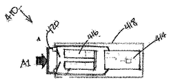
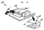
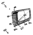
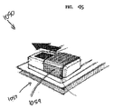
本明細書に開示された装置の実施形態のいずれかでは、図1に示した実施形態におけるように、ポンプアセンブリは、キャニスタのないポンプアセンブリであり得る(ポンプアセンブリが滲出液または液体の回収キャニスタを備えていないことを意味する)。しかしながら、本明細書に開示されたポンプの実施形態のいずれも、キャニスタを含むかまたは支持するように構成されてもよい。また、本明細書に開示された装置の実施形態のいずれでも、ポンプアセンブリの実施形態のいずれも、被覆材に搭載されてもよいし、被覆材により支持されてもよいし、または、被覆材に隣接されてもよい。また、本明細書に開示された装置の実施形態のいずれでも、ポンプアセンブリは、2つ以上のポンプと、1つ、2つ、または、より多くの電力源と、を備えてもよい。本明細書に開示された実施形態のいずれでも、ポンプアセンブリ、電力源、および/または、ポンプアセンブリもしくは電力源を支持もしくは被覆する任意の支持部材もしくは膜は、その任意の色調または着色を含む、人の皮膚に合うように用いられた様々な色のいずれかを持ち得る。さらに、本明細書に開示されたいずれの実施形態でも、ポンプアセンブリは、2011年11月2日に出願された特許文献1(「REDUCED PRESSURE THERAPY APPARATUSES AND METHODS OF USING SAME」という名称)に開示されたポンプアセンブリの実施形態のいずれかの構成部品、特徴、または他の詳細のいずれかを有してもよく、この特許出願は、本明細書において十分に説明されているものとして、本明細書において参照により組み込まれる。 In any of the apparatus embodiments disclosed herein, as in the embodiment shown in FIG. 1, the pump assembly may be a pump assembly without a canister (the pump assembly is an exudate or liquid recovery canister Is not provided). However, any of the pump embodiments disclosed herein may be configured to include or support a canister. Also, any of the apparatus embodiments disclosed herein, any of the pump assembly embodiments may be mounted on, supported by, or supported by a dressing. May be adjacent. Also, in any of the apparatus embodiments disclosed herein, the pump assembly may comprise two or more pumps and one, two, or more power sources. In any of the embodiments disclosed herein, the pump assembly, power source, and / or any support member or membrane that supports or covers the pump assembly or power source includes any color or color thereof. It can have any of a variety of colors used to fit human skin. Further, in any of the embodiments disclosed herein, the pump assembly is disclosed in Patent Document 1 (named “REDUCED PRESSURE THERAPY APPARATUSES AND METHODS OF USING SAME”) filed on Nov. 2, 2011. Which may have any of the components, features, or other details of any embodiment of the pump assembly, and is hereby incorporated by reference as if fully set forth herein. Incorporated by reference.
本明細書に開示された創傷被覆材の実施形態のいずれかは、滲出液キャニスタを使用することなく運転するように配置または構成され得る。任意の被覆材の実施形態は、余分な流体を蒸発することができるように、水蒸気透過性の高い膜を有するように構成されてもよいし、創傷滲出液を安全に吸収するために、超吸収材料を内部に含んでもよい。装置のある実施形態は、使い捨ての治療用に設計され、7日間から11日間のおおよその最大限の使用後に、環境に配慮した方法で廃棄され得る。ポンプのある実施形態は、最大で14日間の運転期間用に設計され、一部は最大で20日間用に設計されている。ポンプは、例えば7日間の後といった、所望の日数の後に、治療を自動的に終了するようにプログラムされてもよく、ポンプのさらなる運転はできなくなる。ある実施形態は、より長い使用または繰り返しの使用ために設計され、滲出液キャニスタを支持するように構成され得る。 Any of the wound dressing embodiments disclosed herein may be arranged or configured to operate without using an exudate canister. Optional dressing embodiments may be configured with a highly water vapor permeable membrane to allow excess fluid to evaporate or to absorb wound exudate safely. An absorbent material may be included therein. Certain embodiments of the device are designed for disposable treatment and can be disposed of in an environmentally friendly manner after an approximate maximum use of 7 to 11 days. Some embodiments of the pump are designed for up to 14 days of operation and some are designed for up to 20 days. The pump may be programmed to automatically terminate therapy after a desired number of days, for example after 7 days, and further operation of the pump will not be possible. Certain embodiments may be designed for longer or repeated use and configured to support an exudate canister.
限定されないが、図示した実施形態を含む任意の被覆材キットの実施形態では、ポンプアセンブリは、被覆材に支持されるかもしくは被覆材に隣接する、または、使用者の体の別の位置にあるかもしくは使用者の衣服にある、十分に小さくて携帯できる大きさのものであり得る。例えば、限定されることはないが、以下でより詳細に説明するように、本明細書に開示された実施形態のいずれかでは、ポンプアセンブリは、被覆材に特別に形成された窪みまたは空間に取り付けられ得るか、1つまたは2つ以上の吸収層もしくは他の被覆材層に埋め込まれ得るか、1つまたは2つ以上の吸収層もしくは他の被覆材層の最上部で支持され得るか、1つまたは2つ以上の吸収層もしくは他の被覆材層に隣接して支持され得るか、または、被覆材により支持され得る。また、開示された任意の実施形態、または、本明細書で参照により組み込まれた任意の実施形態(「本明細書に開示された」と総称される)では、ポンプアセンブリは、接着性医療テープまたは別の方法を用いて、快適な位置で人の皮膚に、被覆材もしくは他のものに隣接して、または、被覆材もしくは他のものに取り付けられる大きさとされ得るか、人の下着またはシャツのポケット内に合うような大きさとされ得るか、あるいは、締め紐、ポーチ、または他の適切な装置もしくは用品を用いて人の体に繋ぎ止められ得る。 In any dressing kit embodiment, including, but not limited to, the illustrated embodiment, the pump assembly is supported by or adjacent to the dressing or at another location on the user's body. Or it can be of a user's clothing that is small enough to be portable. For example, but not limited to, as will be described in more detail below, in any of the embodiments disclosed herein, the pump assembly is in a recess or space specially formed in the dressing. Can be attached, embedded in one or more absorbent layers or other dressing layers, or supported on top of one or more absorbent layers or other dressing layers, It can be supported adjacent to one or more absorbent layers or other dressing layers, or can be supported by a dressing. Also, in any disclosed embodiment, or in any embodiment incorporated herein by reference (collectively referred to as “disclosed herein”), the pump assembly is an adhesive medical tape. Or, using another method, it can be sized to be attached to or adjacent to the skin or other thing on a person's skin in a comfortable position, or a person's underwear or shirt Can be sized to fit within a pocket, or can be secured to a person's body using a lace, pouch, or other suitable device or article.
本明細書に開示された被覆材キットの実施形態のいずれかは、多くの様々な異なる型または変形で製作でき、被覆材の大きさは、幅広い範囲の創傷の大きさを受け入れるように変更され得る。例えば、被覆材キットのいずれかは、以下の大きさの被覆材および創傷パッドまたは他の吸収要素を有するように作られ得る。本明細書に開示された任意の実施形態では、被覆材または創傷パッドの大きさは、被覆材または創傷パッドの面積により定義でき、具体的な長さと幅とは(矩形の場合)、より幅広い創傷の大きさを受け入れるように変更され得る。例えば、被覆材および/または創傷パッドは、矩形、円形、卵形、三角形、五角形、六角形、台形または他の形であり得る。様々な被覆材および創傷パッドの形状および寸法は、以下に列記された、もしくは本出願に開示された面積範囲のいずれかの内であり得るか、または他のものであり得る。したがって、被覆材の寸法および形状は、本開示で明示されたものに限定されず、任意適切な大きさおよび形状であり得る。 Any of the dressing kit embodiments disclosed herein can be made in many different types or variations, and the dressing size can be varied to accommodate a wide range of wound sizes. obtain. For example, any of the dressing kits can be made to have the following size dressings and wound pads or other absorbent elements. In any of the embodiments disclosed herein, the size of the dressing or wound pad can be defined by the area of the dressing or wound pad, and the specific length and width (if rectangular) is wider It can be modified to accept the size of the wound. For example, the dressing and / or wound pad can be rectangular, circular, oval, triangular, pentagonal, hexagonal, trapezoidal, or other shapes. The shapes and dimensions of the various dressings and wound pads can be within any of the area ranges listed below or disclosed in this application, or others. Thus, the dimensions and shape of the dressing are not limited to those specified in this disclosure and may be any suitable size and shape.

本明細書に開示された任意の実施形態では、被覆材は、被覆材のパッド部分または吸収性部分が、おおよそ50×100mm、100×150mm、100×250mm、またはこれらの範囲内の任意の大きさであるような大きさとされ得る。被覆材のある実施形態は、1つの被覆材の大きさ、形状、および構成で、臀部、腕部、大腿部、胴体、背部、および/または他の体の部分に接着できるように、万能であるように構成され得る。 In any embodiment disclosed herein, the dressing is such that the pad portion or absorbent portion of the dressing is approximately 50 × 100 mm, 100 × 150 mm, 100 × 250 mm, or any size within these ranges. Can be as large as possible. Certain embodiments of dressings are universal so that they can adhere to the hips, arms, thighs, torso, back, and / or other body parts with one dressing size, shape, and configuration. Can be configured to be
オーバーレイまたは被覆材のある実施形態は、オーバーレイ層を通る空気流とバクテリアまたは他の汚染物質の流れとに対して実質的に不浸透性であるが、蒸気に対しては透過性である。 Some embodiments of the overlay or dressing are substantially impermeable to air flow through the overlay layer and to bacteria or other contaminants, but are permeable to vapor.
本明細書において十分に説明されているものとして、参照によりその全体が本明細書において組み込まれる特許文献2において、より詳細に説明されているように、本明細書に開示された被覆材の実施形態のいずれでも、吸収材料の層が、透過層の上方に設けられ得る。吸収材料は、発泡材料、不織の天然材料、または合成材料であってもよく、また、特には液体といった創傷部位から取り除かれた流体の貯留部を形成できると共に流体を被覆層に向かって引き込む超吸収材料を、選択的に含み得るか、または、超吸収材料であり得る。吸収層の材料は、創傷被覆材に集められた液体が飛び散るようにして流れるのを防止できる。また、吸収層は、流体が創傷部位から引き込まれて吸収層全体に保持されるように、吸い上げ現象により層全体に流体を分配するのを助けることもできる。これは、吸収層の領域における凝集を防止する助けになる。吸収材料の容量は、負圧が加えられるとき、創傷の産出液の流量を管理するのに十分でなければならない。吸収層の使用において負圧に曝されるため、吸収層の材料は、液体を吸収するように選択され得る。例えば超吸収材料といった、負圧下にあるときに液体を吸収できる多くの材料が存在する。例えば、限定されることはないが、吸収層の任意の実施形態は、ALLEVYN(商標)発泡体、Freudenberg114-224-4、および/またはChem-Posite(商標)11C-450または任意の他の適切な材料を用いて製作できる。他の材料が、本明細書に開示された被覆材の実施形態にとってより適切であり得るし、実施形態で使用され得るし、また、実施形態のものであり得る。適切な超吸収体は、粒状、繊維状、またはそれらの組合せの形態のポリアクリル酸塩系またはカルボメトキシセルロース(carbomethoxycellulose)系の材料を有し得る。 As fully described herein, the implementation of the dressing disclosed herein, as described in more detail in US Pat. No. 5,637,028, which is hereby incorporated by reference in its entirety. In any form, a layer of absorbent material may be provided above the permeable layer. The absorbent material may be a foam material, a non-woven natural material, or a synthetic material, and may form a reservoir of fluid removed from the wound site, particularly a liquid, and draws fluid toward the covering layer A superabsorbent material can optionally be included or can be a superabsorbent material. The material of the absorbent layer can prevent the liquid collected in the wound dressing from splashing and flowing. The absorbent layer can also help distribute fluid throughout the layer by wicking so that fluid is drawn from the wound site and retained throughout the absorbent layer. This helps to prevent agglomeration in the region of the absorbent layer. The capacity of the absorbent material must be sufficient to manage the flow rate of the wound product when negative pressure is applied. Due to exposure to negative pressure in the use of the absorbent layer, the material of the absorbent layer can be selected to absorb the liquid. There are many materials that can absorb liquid when under negative pressure, for example superabsorbent materials. For example, without limitation, any embodiment of the absorbent layer may be ALLEVYN ™ foam, Freudenberg 114-224-4, and / or Chem-Posite ™ 11C-450 or any other suitable Can be made using various materials. Other materials may be more appropriate for the dressing embodiments disclosed herein, may be used in the embodiments, and may be of the embodiments. Suitable superabsorbents can have polyacrylate-based or carbomethoxycellulose-based materials in the form of granules, fibers, or combinations thereof.
本明細書に開示された任意の実施形態では、吸収層は、全体に分散された乾燥粒子の形態で超吸収材料を有する不織のセルロース繊維の層であり得る。ある構成では、綿繊維、セルロース繊維、およびビスコース繊維などの天然繊維および/または合成繊維の使用は、被覆材により取り込まれた液体を素早く均一に分配する助けとなる高速ウィッキング要素(fast wicking element)を導入できる。複数の撚り糸状の繊維を並置すると、液体の分配を助ける繊維パッドにおける強力な毛細管現象をもたらす。この方法で、超吸収材料には液体が効率的に供給される。また、吸収層のすべての領域に液体が供給される。 In any of the embodiments disclosed herein, the absorbent layer can be a layer of nonwoven cellulosic fibers having superabsorbent material in the form of dry particles dispersed throughout. In some configurations, the use of natural and / or synthetic fibers, such as cotton fibers, cellulose fibers, and viscose fibers, allows fast wicking elements (fast wicking) to help quickly and evenly distribute the liquid entrained by the dressing. element). The juxtaposition of multiple strands of fiber results in a strong capillary action in the fiber pad that aids in liquid distribution. In this way, liquid is efficiently supplied to the superabsorbent material. In addition, liquid is supplied to all regions of the absorption layer.
吸い上げ現象は、液体を上部被覆層と接触させる助けとなって、被覆材の蒸散速度を上昇させる助けにもなり得る。吸い上げ現象は、滲出が遅いかまたは停止するとき、液体を創傷床に向かって下方に送る上での助けにもなる。この送る過程は、透過層および下方の創傷床領域を、被覆材内の痂皮形成を防ぐ助けとなる湿潤状態に維持する助けとなる。痂皮形成は、被覆層または裏層下の被覆材の層または構成部品の内部、ならびに、ポートおよび/または導管の内部の両方で、被覆材での創傷の流体の流れを妨げ得ると共に創傷または創傷の部分への減圧の流れを妨げ得る妨害物となる可能性がある。したがって、送る過程は、創傷の治癒に最適とされた環境を維持するのを助けることができる。 The wicking phenomenon can help to bring the liquid into contact with the top coating layer and can also increase the transpiration rate of the coating. The wicking phenomenon also helps to send liquid down towards the wound bed when exudation is slow or stops. This feeding process helps to maintain the permeable layer and the underlying wound bed area in a moist condition that helps prevent scab formation in the dressing. Crust formation can impede the flow of wound fluid through the dressing, both within the dressing layer or component under the dressing or backing layer, and within the port and / or conduit. It can be an obstruction that can impede the flow of reduced pressure to the part of the wound. Thus, the feeding process can help maintain an environment optimized for wound healing.
多孔質材料の層が創傷接触層の上方に配置され得る。この多孔質層、または透過層は、液体および気体を含む流体の、創傷部位から遠ざかって創傷被覆材の上方の層への透過を可能にする。具体的には、透過層は、吸収層が相当量の滲出液を吸収した後であっても、創傷領域全体に負圧を伝えるように開放された空気通路が維持できることを確保できる。層は、前述のように、負圧創傷治療の間に加えられることになる典型的な圧力のもとで、開放したままであるべきであり、その結果、創傷部位全体は均一にされた負圧を受ける。層は、三次元構造を有する材料から形成され得る。例えば、編まれたまたは織られたスペーサ布(例えば、Baltex7970の横糸が編まれたポリエステル)、または、不織布が用いられ得る。他の材料が利用されてもよく、このような材料の例は、特許文献2に説明されており、この特許出願は、本明細書において参照により組み込まれており、本出願の一部とされている。 A layer of porous material can be disposed over the wound contact layer. This porous or permeable layer allows fluids, including liquids and gases, to permeate away from the wound site and into the upper layer of the wound dressing. Specifically, the permeable layer can ensure that an air passage that is open to convey negative pressure to the entire wound area can be maintained even after the absorbent layer has absorbed a substantial amount of exudate. The layer should remain open under the typical pressure that will be applied during negative pressure wound treatment, as described above, so that the entire wound site is made uniform. Receive pressure. The layer can be formed from a material having a three-dimensional structure. For example, a knitted or woven spacer fabric (eg polyester knitted with Baltex 7970 weft) or a non-woven fabric may be used. Other materials may be utilized and examples of such materials are described in US Pat. No. 6,057,056, which is hereby incorporated by reference and made part of this application. ing.
本明細書に開示された任意の実施形態では、透過層は、2011年4月21に出願された特許文献22(「WOUND DRESSING AND METHOD OF USE」という名称)に開示された被覆材の任意の実施形態などの三次元ポリエステルスペーサ布層を備えてもよく、この特許出願は、本明細書において十分に説明されているものとして、本明細書において参照により組み込まれる。透過層のある実施形態は、84/144の織り方とされたポリエステル(材料組成に関して、およそ24.5%、または、およそ22%からおよそ27%までであり得る)である最上層(つまり、使用際に創傷床から遠位にある層)と、100デニールの平面のポリエステル(材料組成に関して、およそ31.4%、または、およそ28%からおよそ34%までであり得る)であり得る最下層(つまり、使用際に創傷床の近位にある層)と、これらの2つの層の間に挟まれて形成され、編まれたポリエステルビスコース、セルロースなどの単一フィラメントの繊維(材料組成に関して、およそ44.1%、または、およそ40%からおよそ48%までであり得る)により画定された領域である第3層と、を備えてもよい。繊維で他の適切な材料と他の線形質量密度とが用いられてもよい。 In any of the embodiments disclosed herein, the transmissive layer is made of any of the coating materials disclosed in US Pat. No. 5,834,009 filed Apr. 21, 2011 (named “WOUND DRESSING AND METHOD OF USE”). A three-dimensional polyester spacer fabric layer, such as an embodiment, may be provided, and this patent application is hereby incorporated by reference as if fully set forth herein. One embodiment of the permeable layer is a top layer that is 84/144 woven polyester (which can be approximately 24.5%, or approximately 22% to approximately 27%, in terms of material composition) (ie, A layer that is distal to the wound bed in use) and a bottom layer that can be 100 denier planar polyester (can be approximately 31.4%, or approximately 28% to approximately 34%, in terms of material composition) (That is, the layer proximal to the wound bed in use) and knitted polyester viscose, cellulose, etc., single filament fibers, sandwiched between these two layers (with respect to material composition) , Approximately 44.1%, or approximately 40% to approximately 48%). Other suitable materials and other linear mass densities may be used for the fibers.
また、透過層の任意の実施形態は、以下のニードルアレンジメントパラメータのうちのいずれかを用いて形成できる。 Also, any embodiment of the transmission layer can be formed using any of the following needle arrangement parameters.
離間された層同士におけるフィラメント数の間のこの違いは、透過層を通る水分の流れの制御を助ける。特に、最上層において、より多くのフィラメント数を有することで、つまり最下層で用いられる糸よりも多くのフィラメントを有する糸から最上層が作られることで、液体は、最下層よりも最上層に沿って吸い上げられる傾向がある。使用の際、この差は、創傷床から、吸収層が液体を離して固定する助けとなる被覆材の中心領域へと、液体を引き込む傾向があるか、または、この差自体が、液体が発散される被覆層に向かって、液体をさらに吸い上げる。 This difference between the number of filaments in the spaced apart layers helps control the flow of moisture through the permeable layer. In particular, by having a higher number of filaments in the top layer, i.e. making the top layer out of yarns having more filaments than used in the bottom layer, the liquid is in the top layer rather than the bottom layer. Tend to be sucked along. In use, this difference tends to draw the liquid from the wound bed to the central area of the dressing that helps the absorbent layer separate and fix the liquid, or the difference itself can cause the liquid to diverge. The liquid is further sucked up toward the coating layer.
材料層の組成
好ましくは、透過層を横断する(つまり、最上部のスペーサ層と最下部のスペーサ層との間に形成される通路領域に直交する)液体の流れを改善するために、三次元布は、ドライクリーニング剤(限定されることはないが、ペルクロロエチレンなど)で処理されて、透過層の親水性能力と干渉する可能性のある前もって使用される鉱油、脂質、および/または蝋などの任意の工業製品を除去するのを助ける。ある実施形態では、三次元スペーサ布が親水性剤(限定されることはないが、Rudolph Groupから入手可能なFeran Ice 30g/lなど)で洗浄される追加製作ステップが、後で実施され得る。この工程のステップは、材料の表面張力が、水などの液体が三次元で編まれた布と接するとすぐに布に入り込むほど低くなることを確実にする助けとなる。また、あらゆる滲出液の液体傷害部分の流れの制御における助けともなる。
The composition of the material layer, preferably three-dimensional to improve the flow of liquid across the permeable layer (ie perpendicular to the channel region formed between the uppermost spacer layer and the lowermost spacer layer) The fabric is treated with a dry cleaning agent (such as, but not limited to, perchlorethylene) and used in advance with mineral oils, lipids, and / or waxes that may interfere with the hydrophilic capacity of the permeable layer. Help to remove any industrial products such as. In certain embodiments, an additional fabrication step can be performed later where the three-dimensional spacer fabric is washed with a hydrophilic agent (such as, but not limited to, Ferran Ice 30 g / l available from Rudolph Group). This process step helps to ensure that the surface tension of the material is so low that it enters the fabric as soon as it touches a fabric woven in three dimensions, such as water. It also helps in controlling the flow of liquid injuries in any exudate.
ある実施形態では、吸収層はエアレイド材料であってもよい。熱溶解性繊維は、パッドの構造を一体に保持する助けとするために、選択的に使用され得る。超吸収性の粒子を使用するよりも、または、このような使用に加えて、本発明のある実施形態によれば、超吸収性の繊維が利用できることを理解されたい。適切な材料の例には、米国のEmerging Technologies Inc(ETi)から入手可能なProduct Chem-Posite(商標)11Cがある。 In some embodiments, the absorbent layer may be an airlaid material. Hot melt fibers can be used selectively to help hold the pad structure together. It should be understood that superabsorbent fibers can be utilized in accordance with certain embodiments of the present invention rather than or in addition to using superabsorbent particles. An example of a suitable material is Product Chem-Posite ™ 11C available from Emerging Technologies Inc (ETi), USA.
選択的に、吸収層は、合成短繊維および/または二成分短繊維および/または天然短繊維および/または超吸収性繊維を含んでもよい。吸収層の繊維は、ラテックス結合、熱結合、水素結合、任意の結合技術の組合せ、または他の固定機構により、一体に固定される。本明細書に開示された任意の実施形態では、吸収層は、吸収層内の超吸収粒子を固定するように作用する繊維により形成され得る。これは、超吸収粒子が吸収層の外部へと、および、下方の創傷床に向かって移動しないことを確保する助けとなる。これは、負圧が加えられたとき、吸収パッドが下向きにつぶれる傾向があり、この動作が超吸収粒子の物質を、それらが吸収層の繊維構造により離して固定されていない場合に、創傷床のある方向へと押し付けることになるため、特に有益である。 Optionally, the absorbent layer may comprise synthetic staple fibers and / or bicomponent staple fibers and / or natural staple fibers and / or superabsorbent fibers. The fibers of the absorbent layer are secured together by latex bonding, thermal bonding, hydrogen bonding, any combination of bonding techniques, or other securing mechanisms. In any embodiment disclosed herein, the absorbent layer may be formed by fibers that act to secure the superabsorbent particles within the absorbent layer. This helps to ensure that the superabsorbent particles do not move out of the absorbent layer and toward the underlying wound bed. This is because the absorbent pad tends to collapse downward when negative pressure is applied, and this action causes the wound bed when the superabsorbent particles are not anchored apart by the fibrous structure of the absorbent layer. This is particularly beneficial because it will push in a certain direction.
吸収層は、複数の繊維の層を含み得る。好ましくは、繊維は、糸状であり、セルロース、ポリエステル、ビスコースなどから作られる。好ましくは、乾燥吸収粒子は、使える状態にある吸収層の至る所に分配されている。本明細書に開示された任意の実施形態では、吸収層は、セルロース繊維のパッドと、複数の超吸収粒子と、を備えることができる。追加の実施形態では、吸収層は、無作為に配向されたセルロース繊維の不織の層である。 The absorbent layer may include a plurality of fiber layers. Preferably, the fibers are thread-like and are made from cellulose, polyester, viscose and the like. Preferably, the dry absorbent particles are distributed throughout the absorbent layer ready for use. In any of the embodiments disclosed herein, the absorbent layer can comprise a cellulose fiber pad and a plurality of superabsorbent particles. In additional embodiments, the absorbent layer is a non-woven layer of randomly oriented cellulose fibers.
超吸収の粒子/繊維は、例えば、ポリアクリル酸ナトリウムもしくはカルボメトキシセルロースの材料などや、または、液体の自身の重量の何倍も吸収できる任意の材料であり得る。ある実施形態では、材料は、自身の重量の5倍を超える0.9W/W%の生理食塩水など、または、自身の重量の15倍を超える0.9W/W%の生理食塩水など、または、ある実施形態では、自身の重量の20倍を超える0.9W/W%の生理食塩水などを吸収できる。好ましくは、材料は、自身の重量の30倍を超える0.9W/W%の生理食塩水などを吸収できる。吸収層は、吸気ポートを設けるために、1つまたは2つ以上の貫通孔を備えてもよい。本明細書に開示された任意の実施形態では、疎水性フィルタ、または、被覆材のポートもしくは開口を通る空気もしくは気体の流れを可能にすると共に被覆材のポートもしくは開口を通る液体もしくは固体の流れを防止するように構成された他のフィルタもしくは物体が、任意の液体または固体がポンプに入るのを防止するために、ポンプの上流に位置付けられ得る。 The superabsorbent particles / fibers can be, for example, a sodium polyacrylate or carbomethoxycellulose material, or any material that can absorb many times its own weight of the liquid. In some embodiments, the material is 0.9 W / W% saline, such as greater than 5 times its own weight, or 0.9 W / W% saline, such as greater than 15 times its own weight, etc. Or, in an embodiment, 0.9 W / W% physiological saline or the like exceeding 20 times its own weight can be absorbed. Preferably, the material can absorb 0.9 W / W% saline, etc., which is more than 30 times its own weight. The absorbent layer may comprise one or more through holes to provide an intake port. In any embodiment disclosed herein, a hydrophobic or liquid or solid flow that allows air or gas flow through the port or opening of the dressing and allows flow of air or gas through the port or opening of the dressing. Other filters or objects configured to prevent can be positioned upstream of the pump to prevent any liquid or solid from entering the pump.
ある実施形態では、創傷部位は、一部または全部が創傷充填材料で満たされ得る。より深い創傷は、このような充填材料から恩恵を受けることができる。創傷充填材料は、創傷被覆材に加えて使用できるか、または、創傷被覆材と一体であってもよい。創傷充填材料は、概して、例えば発泡体(網状発泡体を含む)およびガーゼといった、多孔質で順応可能な材料を備え得る。好ましくは、創傷充填材料は、任意の空の空間を満たすように、創傷部位内に一致するような大きさまたは形状とされる。そして、創傷被覆材が、創傷部位と、創傷部位に被さる創傷充填材料と、を覆って置かれ得る。創傷充填材料が用いられるとき、創傷被覆材が創傷部位を覆って封着されると、TNPがポンプから創傷被覆材および創傷充填材料を通して創傷部位へと伝達される。この負圧は、創傷滲出液および他の液体または他の分泌物を創傷部位から引き込む。 In certain embodiments, the wound site may be partially or fully filled with wound filling material. Deeper wounds can benefit from such filling materials. The wound filling material can be used in addition to the wound dressing or can be integral with the wound dressing. The wound filling material may generally comprise a porous and conformable material such as foam (including reticulated foam) and gauze. Preferably, the wound filling material is sized or shaped to conform within the wound site to fill any empty space. A wound dressing can then be placed over the wound site and the wound filler material covering the wound site. When a wound filling material is used, TNP is transferred from the pump through the wound dressing and wound filling material to the wound site as the wound dressing is sealed over the wound site. This negative pressure draws wound exudate and other fluids or other secretions from the wound site.
本明細書に開示された任意の被覆材キットの実施形態の被覆材は、創傷被覆材の幅にわたって延在すると共に気体に対して不浸透性であるが水蒸気に対して浸透性のある被覆層を、備え得る。被覆層は、例えば、ポリウレタン膜(例えば、Elastollan SP9109)、または、一方の側に圧力感応型の接着剤を有する任意の他の適切な材料であってもよく、実質的に気体不浸透性であり、それにより、創傷を覆う実質的に封じられた包囲領域を作り出す。この方法で、事実上の空間が被覆層と創傷部位との間に作られ、その空間では負圧が確立され得る。被覆層は、例えば接着剤または溶着技術を用いて、被覆材の周囲の周りの境界領域で創傷接触層に封着されるため、空気が境界領域を通して引き込まれないことを確保できる。被覆層は、創傷を外部の細菌汚染から保護でき(細菌バリア)、創傷滲出液からの液体を、層を通して送らせることができ、また、膜の外表面から蒸発させることができる。被覆層は、ポリウレタン膜およびその膜に拡げられた接着剤パターンを備え得る。ポリウレタン膜は、水蒸気浸透性であり、濡れたときに水の伝達速度を増加させる材料から製作され得る。 The dressing of any dressing kit embodiment disclosed herein is a dressing that extends across the width of the wound dressing and is impermeable to gas but permeable to water vapor Can be provided. The covering layer may be, for example, a polyurethane membrane (eg, Elastollan SP9109) or any other suitable material having a pressure sensitive adhesive on one side and is substantially gas impermeable. Yes, thereby creating a substantially enclosed surrounding area that covers the wound. In this way, a virtual space is created between the covering layer and the wound site, in which negative pressure can be established. Since the covering layer is sealed to the wound contact layer at the border area around the periphery of the dressing, for example using an adhesive or welding technique, it can be ensured that no air is drawn through the border area. The covering layer can protect the wound from external bacterial contamination (bacterial barrier), allow fluid from the wound exudate to pass through the layer and evaporate from the outer surface of the membrane. The covering layer may comprise a polyurethane film and an adhesive pattern spread over the film. Polyurethane membranes can be fabricated from materials that are water vapor permeable and increase the rate of water transmission when wet.
オリフィスが、負圧を被覆材に加えるようにするために、被覆膜に設けられ得る。前述のように、ある実施形態では、オリフィスを通して負圧を伝えることができる吸気ポートが、オリフィスを覆う被覆膜の最上部に封着され得るか、または、ポンプアセンブリがオリフィスを覆って直に装着され得る。ポートまたはポンプアセンブリは、アクリル、シアノアクリレート、エポキシ、紫外線硬化性、または熱溶解性の接着剤などの接着剤を用いて、被覆膜に付着および封着され得る。用いられる場合、ポートは、例えば、ショアAスケールで30から90までの硬さを有するポリエチレン、ポリ塩化ビニル、シリコン、またはポリウレタンといった、柔らかいポリマーから形成され得る。 Orifices can be provided in the coating membrane to cause negative pressure to be applied to the coating. As described above, in some embodiments, an intake port that can transmit negative pressure through the orifice can be sealed to the top of the coating membrane covering the orifice, or the pump assembly can be directly over the orifice. Can be mounted. The port or pump assembly can be attached and sealed to the coating using an adhesive such as an acrylic, cyanoacrylate, epoxy, UV curable, or hot melt adhesive. If used, the port may be formed from a soft polymer such as, for example, polyethylene, polyvinyl chloride, silicone, or polyurethane having a hardness of 30 to 90 on the Shore A scale.
被覆材は、液体に対して不浸透性だが気体に対して浸透性のフィルタ要素を備え得る。フィルタ要素は、液体が創傷被覆材から漏れるのを実質的に防止または抑制するために、液体バリアとして作用でき、また、臭気バリアとしても作用できる。フィルタ要素は、細菌バリアとしても機能できる。ある実施形態では、フィルタ要素の細孔の大きさはおよそ0.2μmであり得る。フィルタ要素のフィルタ材料に適した材料には、MMT範囲から延伸されたPTFEの0.2ミクロンのGore(商標)、PALL Versapore(商標)200R、およびDonaldson(商標)TX6628が含まれる。したがって、フィルタ要素は、オリフィスを通して気体を排出させることができる。しかしながら、液体、微粒子、および病原菌は、被覆材に含まれる。フィルタに関する他の詳細事項は、特許文献2に開示されており、本明細書では、参照により組み込まれている。 The dressing may comprise a filter element that is impermeable to liquids but permeable to gases. The filter element can act as a liquid barrier and can also act as an odor barrier to substantially prevent or inhibit liquid from leaking from the wound dressing. The filter element can also function as a bacterial barrier. In certain embodiments, the pore size of the filter element can be approximately 0.2 μm. Suitable materials for the filter element filter material include PTFE 0.2 micron Gore (TM), PALL Versapore (TM) 200R, and Donaldson (TM) TX6628 stretched from the MMT range. Thus, the filter element can exhaust gas through the orifice. However, liquids, particulates, and pathogens are included in the dressing. Other details regarding the filter are disclosed in US Pat.
本明細書で説明されている創傷被覆材ならびにその製作方法および使用方法は、以下の特許および特許出願で説明された特徴、構成、および材料も組み込むことができ、それらの特許および特許出願の各々は、本開示の一部とされているかのように、それらの全体が参照により本明細書に組み込まれる。特許文献3、特許文献4、特許文献5、特許文献6、特許文献7、特許文献8、特許文献9、特許文献10、特許文献11、特許文献12、特許文献13、特許文献14、特許文献15、特許文献16、特許文献17、特許文献18、特許文献19、さらには2011年4月15日に出願された特許文献20、および2011年4月15日に出願された特許文献21。参照により組み込まれたこれらの特許および特許出願のうち、本出願で説明されているものと同様の構成部品についての特徴、構成、材料、および製作の方法または使用方法は、本出願の実施形態に、置き換え、追加、または実施できる。
The wound dressings described herein and their methods of making and using can also incorporate the features, configurations, and materials described in the following patents and patent applications, each of those patents and patent applications: Are incorporated herein by reference in their entirety as if they were part of this disclosure. Patent Literature 3,
運転中、創傷被覆材は、創傷空洞を形成する創傷部位を覆って封着され得る。ポンプアセンブリは、負圧の供給源を被覆材に提供できる。流体は、創傷接触層の下の創傷部位から、創傷被覆材を通してオリフィスに向かって引き込まれ得る。流体は、透過層を通してオリフィスに向かって移動できる。流体が透過層を通して引き込まれるにつれて、創傷滲出液が吸収層に吸収され得る。 During operation, the wound dressing can be sealed over the wound site forming the wound cavity. The pump assembly can provide a source of negative pressure to the dressing. Fluid can be drawn from the wound site under the wound contact layer through the wound dressing toward the orifice. The fluid can move through the permeable layer toward the orifice. As fluid is drawn through the permeable layer, wound exudate can be absorbed into the absorbent layer.
創傷被覆材の一般的な形状は、正方形、卵形、三角形、または他の形であり得る。被覆材は、丸くされたコーナーの領域を有し得る。本発明の他の実施形態による創傷被覆材は、正方形、円形、または楕円形の被覆材など、異なる形状とされ得ることを理解されたい。 The general shape of the wound dressing can be square, oval, triangular, or other shapes. The dressing may have rounded corner areas. It should be understood that wound dressings according to other embodiments of the present invention can be of different shapes, such as square, round, or oval dressings.
創傷被覆材の所望の大きさは、それが用いられることになる創傷の大きさおよび種類に基づいて選択できる。任意の実施形態において、必然とはされないが、創傷被覆材は、その長手軸線において20から40cmの間で、その短手軸線において10から25cmの間の寸法であり得る。例えば、被覆材は、およそ10×20cm、10×30cm、10×40cm、15×20cm、および15×30cmの大きさ、または、これらの範囲もしくは他の範囲内の任意の他の大きさで提供され得る。 The desired size of the wound dressing can be selected based on the size and type of wound on which it will be used. In any embodiment, although not required, the wound dressing can be between 20 and 40 cm in its longitudinal axis and between 10 and 25 cm in its short axis. For example, the dressing is provided in a size of approximately 10 × 20 cm, 10 × 30 cm, 10 × 40 cm, 15 × 20 cm, and 15 × 30 cm, or any other size within these or other ranges Can be done.
例えば単一フィラメントの層により離間された2つの層といった、透過層が三次元の編物層として形成された本発明のある実施形態が、ここまで説明されてきたが、本発明のある実施形態は、このような材料の使用に制限されないことを理解されたい。ある実施形態では、このような三次元で編まれた材料の代替として、幅広い様々な材料の1つまたは2つ以上の層が利用され得る。各々の場合で、本発明の実施形態によれば、透過層の層により呈される開口は、使用中に創傷の近位に配置されることになる被覆材の側から離れるにつれてより幅広くなっている。本明細書に開示された任意の実施形態では、透過層は、連続気泡発泡体の複数の層により提供され得る。必然とはされないが、発泡体は網状にされた連続気泡発泡体であり得る。発泡体は、親水性であってもよいし、または、水性流体を吸い上げることができてもよい。各々の層の細孔の大きさは、創傷側に最も近位にある発泡体の層において、細孔が最も小さい大きさを有するように選択される。1つだけのさらなる発泡体の層が利用される場合、その層は、第1層の細孔の大きさより大きい細孔の大きさを有する。これは、固体の微粒子が下方の層で捕捉される助けとなり、したがって、下方の層を、結果的に被覆材を通して空気を送ることができる開放した構成に維持する助けとなる。本明細書に開示された任意の実施形態では、2つ、3つ、4つ、またはさらに多くの発泡体の層が含まれ得る。発泡体の層は、例えば、大きな細孔の大きさを有する発泡体を選択し、その後、それをより小さな具合に成るように細孔を詰まらせることになる材料へと繰り返し浸すことで、一体的に形成できる。あるいは、複数の発泡体の層により形成された透過層が、異なる種類の発泡体を積層構成で重ねることにより、または、公知の方法により適当な位置でこのようの発泡体の層を固定することにより、提供できる。 While certain embodiments of the present invention have been described so far, for example two layers separated by a single filament layer, the permeable layer has been formed as a three-dimensional knitted layer. It should be understood that the use of such materials is not limiting. In certain embodiments, one or more layers of a wide variety of materials may be utilized as an alternative to such three-dimensional knitted materials. In each case, according to embodiments of the present invention, the opening presented by the layer of permeable layer becomes wider as it moves away from the side of the dressing that will be placed proximal to the wound during use. Yes. In any of the embodiments disclosed herein, the permeable layer may be provided by multiple layers of open cell foam. Although not necessary, the foam can be a reticulated open cell foam. The foam may be hydrophilic or may be capable of sucking up an aqueous fluid. The pore size of each layer is selected so that the pores have the smallest size in the foam layer most proximal to the wound side. If only one additional foam layer is utilized, the layer has a pore size that is greater than the pore size of the first layer. This helps solid particulates to be trapped in the lower layer, thus helping to maintain the lower layer in an open configuration that can eventually send air through the dressing. In any of the embodiments disclosed herein, two, three, four, or more foam layers may be included. The foam layer can be integrated, for example, by selecting a foam having a large pore size and then repeatedly immersing it in a material that will clog the pores to a smaller degree. Can be formed. Alternatively, a permeable layer formed by a plurality of foam layers may be fixed by stacking different types of foams in a laminated configuration, or by fixing such foam layers at appropriate positions by known methods. Can be provided.
被覆材の一部の実施形態は、被覆材の再配置を許容するように構成され得る。本明細書に開示された任意の実施形態では、被覆材は、シリコン系の接着剤などの接着剤で覆われる創傷接触面を有し得る。本明細書において十分に説明されているものとして、本明細書において参照により組み込まれる特許文献2に説明されているように、必然とはされないが、本明細書に開示された創傷被覆材の実施形態のいずれかの下面は、選択的な創傷接触層を備えることができる。本明細書に開示された被覆材の実施形態のいずれも、創傷接触層なしで作ることができる。創傷接触層は、例えば、熱ピンの工程、レーザー切断工程、超音波工程、もしくは、ある他の方法を介して多孔質とされ得るか、もしくは、穿孔され得る、または、液体および気体に浸透性があるように作られ得るポリウレタン層、ポリエチレン層、または、他の可撓性の層であり得る。穿孔は、流体および/または気体を、層を通して流すことができる。創傷接触層は、創傷被覆材の他の材料への組織成長を妨げる助けとなり得る。 Some embodiments of the dressing may be configured to allow the repositioning of the dressing. In any of the embodiments disclosed herein, the dressing may have a wound contact surface that is covered with an adhesive, such as a silicone-based adhesive. As described fully in the present specification, as described in US Pat. No. 6,057,089, which is hereby incorporated by reference, the implementation of the wound dressing disclosed herein is not required. Any underside of the form can be provided with an optional wound contact layer. Any of the dressing embodiments disclosed herein can be made without a wound contact layer. The wound contact layer can be made porous, for example through a hot pin process, a laser cutting process, an ultrasonic process, or some other method, or pierced, or permeable to liquids and gases. It can be a polyurethane layer, a polyethylene layer, or other flexible layer that can be made to be. Perforations can allow fluids and / or gases to flow through the layers. The wound contact layer can help prevent tissue growth on other materials of the wound dressing.
接触層の穿孔は、この要件に合うように十分に小さい大きさとされ得るが、なおも流体の通過を可能にする。例えば、接触層は、組織の創傷被覆材への成長を妨げる助けとなる十分に小さい一方で創傷滲出液が被覆材へと流すことができると考えられる、およそ0.025mmからおよそ1.8mmまでの範囲、または、およそ1.2mmからおよそ1.8mmまでの範囲にある大きさを有するスリットまたは孔として形成された穿孔を有してもよい。任意の実施形態では、そのため、穿孔は、およそ1.2mmからおよそ2.8mmまで、または、およそ1.2mmからおよそ1.8mmまでの直径の範囲にある孔として形成され得る。任意の実施形態における孔の間隔または密度は、およそ8孔/cm2、または、およそ6孔/cm2からおよそ10孔/cm2までであり得る。この開示を通して用いられるように、定義されていないとしても、用語は、おおよそ提示された値の±10%の範囲を説明するように用いられ得る。また、接触層の任意の実施形態では、孔は、およそ3.655mmの三角形状のピッチで形成され得る。本明細書に開示された創傷接触層の実施形態のいずれも、シリコンから形成され得る。 The perforations in the contact layer can be sized sufficiently small to meet this requirement, but still allow the passage of fluid. For example, the contact layer is small enough to help prevent the tissue from growing into a wound dressing, while wound exudate is believed to be able to flow into the dressing, from about 0.025 mm to about 1.8 mm Or perforations formed as slits or holes having a size in the range of approximately 1.2 mm to approximately 1.8 mm. In any embodiment, the perforations can thus be formed as holes that range in diameter from about 1.2 mm to about 2.8 mm, or from about 1.2 mm to about 1.8 mm. The spacing or density of the holes in any embodiment can be approximately 8 holes / cm 2 , or from approximately 6 holes / cm 2 to approximately 10 holes / cm 2 . As used throughout this disclosure, the term may be used to describe a range of approximately ± 10% of the presented value, even if not defined. Also, in any embodiment of the contact layer, the holes can be formed with a triangular pitch of approximately 3.655 mm. Any of the embodiments of the wound contact layer disclosed herein can be formed from silicon.
創傷接触層は、創傷の負圧を維持するために、創傷被覆材全体を一体に保持する助けとなり得ると共に、吸収パッドの周りで気密な封着を作り出す助けとなり得る。創傷接触層は、選択的な下方および上方の接着剤層(図示省略)のためのキャリアとしても機能する。例えば、下方の圧力感応型の接着剤が創傷被覆材の下側の面に設けられ得る一方で、上方の圧力感応型の接着剤層が創傷接触層の上面に設けられ得る。圧力感応型の接着剤は、シリコン、熱溶解性、親水コロイド、もしくはアクリル系の接着剤、または他のこのような接着剤は、創傷接触層の両側、もしくは、選択的に選択された一方の側に形成されてもよいし、または、創傷接触層のいずれの側にも形成されなくてもよい。下方の圧力感応型の接着剤層が利用されるとき、これは、創傷被覆材を創傷部位の周りの皮膚に付着する助けとなる。 The wound contact layer can help hold the entire wound dressing together to maintain the negative pressure of the wound and can help create an airtight seal around the absorbent pad. The wound contact layer also serves as a carrier for the selective lower and upper adhesive layers (not shown). For example, a lower pressure sensitive adhesive may be provided on the lower surface of the wound dressing, while an upper pressure sensitive adhesive layer may be provided on the upper surface of the wound contact layer. Pressure sensitive adhesives can be silicon, hot-melt, hydrocolloid, or acrylic adhesives, or other such adhesives on either side of the wound contact layer or one of the selectively selected It may be formed on the side or may not be formed on either side of the wound contact layer. When a lower pressure sensitive adhesive layer is utilized, this helps to adhere the wound dressing to the skin around the wound site.
前述のように、開示された被覆材キット、または、本明細書で参照により組み込まれた被覆材キットで使用するための任意の被覆材の実施形態は、接着剤で覆われた底の(例えば、創傷と接触する)面を有し得る。本明細書に開示された任意の実施形態では、前述のように、接着剤は、例えば、ポリシロキサン、ポリオルガノシロキサン、または、他の重合体の圧力感応型のシリコン接着剤を含む、シリコン接着剤であり得る。例えば、ポリジメチルシロキサンなどが用いられ得る。接着剤配合は、アルキルペンダントシロキサンの混合であってもよく、そのアルキルペンダントシロキサンは、最終的な重合のステップが続く流し込むことまたは拡げることを引き起こせるように、2つの部品が触媒と混合するにつれて、流し込みおよび拡げることができる。本明細書に開示された任意の実施形態では、被覆材層は、穿孔されていないシリコンの接着剤被覆(被覆重量は公称130gsm)と、押し出されたEU30ポリウレタン透明膜(27〜37gsm)の両側に被覆された完全に拡げられたアクリルの接着剤(27〜37gsm)と、を備え得る。このような構成の水蒸気透過性は、およそ367gm−2/24hrsからおよそ405gm−2/24hrsまでの間であり得るか、または、382gm−2/24hrsの平均水蒸気透過性であり得る。 As noted above, any dressing embodiment for use in the disclosed dressing kit, or a dressing kit incorporated herein by reference, may include an adhesive-covered bottom (e.g., In contact with the wound). In any of the embodiments disclosed herein, as described above, the adhesive comprises a silicon adhesive, including, for example, a polysiloxane, polyorganosiloxane, or other polymeric pressure sensitive silicone adhesive. It can be an agent. For example, polydimethylsiloxane can be used. The adhesive formulation may be a mixture of alkyl pendant siloxanes, which can be poured or expanded as the two parts are mixed with the catalyst so that the final polymerization step can be followed. Can be poured and spread. In any of the embodiments disclosed herein, the dressing layer comprises an unperforated silicone adhesive coating (coating weight nominally 130 gsm) and both sides of an extruded EU30 polyurethane transparent membrane (27-37 gsm). And fully expanded acrylic adhesive (27-37 gsm). The water vapor permeability of such a configuration can be between about 367 gm −2 / 24 hrs to about 405 gm −2 / 24 hrs, or can be an average water vapor permeability of 382 gm −2 / 24 hrs.
本明細書に開示された被覆材の実施形態に適したシリコン接着剤層のある実施形態または構成は、およそ350gm−2/24hrsからおよそ410gm−2/24hrsまでの間の水蒸気伝達速度を有し得る。適切には、本明細書に開示された被覆材の実施形態に適したシリコンの接着剤層のある実施形態または構成の平均水蒸気透過性は、およそ380gm−2/24hrsであり得る。本明細書に開示された被覆材の実施形態の一部は、自身に被覆されたWacker silres PSA 45圧力感応型接着剤を有し得る。 Embodiments or configurations of silicone adhesive layer for embodiments of dressing disclosed herein have a water vapor transmission rate of between approximately 350 gm -2 / 24hrs to approximately 410gm -2 / 24hrs obtain. Suitably, the average water vapor permeability of an embodiment or configuration of a silicon adhesive layer suitable for the dressing embodiments disclosed herein may be approximately 380 gm −2 / 24 hrs. Some of the dressing embodiments disclosed herein may have a Wacker silres PSA 45 pressure sensitive adhesive coated thereon.
また、本明細書に開示された被覆材の実施形態のいずれも、被覆材に含まれるか、または、被覆材の1つまたは2つ以上の表面に被覆される抗菌性の薬剤または物質を備え得る。例えば、限定されることはないが、被覆材は、例えば、創傷接触層におけるナノ結晶の銀の薬剤もしくは他のもの、および/または、吸収層における硫酸銀ジアジンもしくは他のものといった、抗菌剤を含み得る。これらは、それぞれ、創傷の微生物と、吸収母材の微生物とを根絶できる。本明細書に開示された任意の被覆材の実施形態の創傷接触層は、限定されることはないが、2008年5月21に出願された特許文献24(「ANTIMICROBIAL BIGUANIDE METAL COMPLEXES」という名称)に開示されたものなど、ナノ結晶の銀の薬剤、銀塩、銅塩、または金塩を内部または表面に有してもよく、この特許出願は、本開示の一部とされているかのように、参照により本明細書に組み込まれている。また、本明細書に開示された任意の被覆材の実施形態の創傷接触層は、PHMB、クロロヘキサダイン(chlorohexadine)、過酸化物、次亜塩素酸塩、または他の漂白剤を内部または表面に有してもよい。 Also, any of the dressing embodiments disclosed herein comprise an antimicrobial agent or substance that is included in the dressing or that is coated on one or more surfaces of the dressing. obtain. For example, but not limited to, the dressing may contain an antibacterial agent such as, for example, nanocrystalline silver drug or other in the wound contact layer and / or silver sulfate diazine or other in the absorbent layer. May be included. They can eradicate wound microorganisms and absorption matrix microorganisms, respectively. The wound contact layer of any dressing embodiment disclosed herein is, but is not limited to, Patent Document 24 (named “ANTIMICROBIAL BIGUANIDE METAL COMPLEXES”) filed May 21, 2008. Nanocrystalline silver agents, silver salts, copper salts, or gold salts may be present in or on the surface, such as those disclosed in US Pat. Which is incorporated herein by reference. Also, the wound contact layer of any of the dressing embodiments disclosed herein may contain PHMB, chlorohexadine, peroxide, hypochlorite, or other bleaching agent in or on the surface. You may have.
このような薬剤のうちの1つまたは複数が、別々または一緒に使われ得る。これらは、創傷の微生物と、吸収母材の微生物とを削減または根絶できる。さらなる選択肢として、例えば、イブプロフェンなどの痛み抑制剤といった、他の活性成分が含まれ得る。また、成長因子などの細胞の活動を高める薬剤、または、マトリクスメタロプロテイナーゼ抑制剤などの酵素を抑制する薬剤、メタロプロテイナーゼの組織阻害剤(TIMPS)または鉛キレート剤などが、利用され得る。さらなる選択肢として、活性炭、シクロデキストリン、ゼオライトなどの臭気捕捉要素が、吸収層に含まれ得るか、または、フィルタ層の上方にさらなる層として含まれ得る。 One or more of such agents can be used separately or together. They can reduce or eradicate wound microbes and absorbent matrix microbes. As a further option, other active ingredients may be included, for example pain inhibitors such as ibuprofen. In addition, agents that enhance cellular activity such as growth factors, agents that suppress enzymes such as matrix metalloproteinase inhibitors, tissue inhibitors of metalloproteinases (TIMPS), lead chelators, and the like can be used. As a further option, an odor trapping element such as activated carbon, cyclodextrin, zeolite, etc. can be included in the absorbent layer or can be included as a further layer above the filter layer.
また、接着剤固定片が、本明細書に開示された被覆材の実施形態のいずれの周辺の縁の周りに位置付けられており、追加支持体を被覆材にもたらしている。このような固定片は、創傷部位の周囲で患者の皮膚に対して追加封着を提供するために、ある状況では有利であり得る。例えば、封着片または固定片は、患者がより動ける場合に追加封着を提供できる。ある場合には、固定片は、特に、被覆材が届きにくい領域または曲線のある領域に配置される場合、ポンプアセンブリの作動の前に使用され得る。本明細書に開示された任意の実施形態では、被覆材キットには、5つまでの封着片が設けられ得る。 Also, an adhesive fixture is positioned around the peripheral edge of any of the dressing embodiments disclosed herein, providing additional support to the dressing. Such a fixation piece may be advantageous in some situations to provide an additional seal to the patient's skin around the wound site. For example, a sealing piece or fixed piece can provide additional sealing when the patient is more movable. In some cases, the fixed piece may be used prior to operation of the pump assembly, particularly if it is placed in areas where the dressing is difficult to reach or is curved. In any of the embodiments disclosed herein, the dressing kit can be provided with up to five sealing pieces.
さらに、本明細書に開示されたある実施形態は、負圧治療の装置および被覆材を含むシステムと、このような負圧治療装置を負圧治療被覆材との使用ために運転する方法およびアルゴリズムとに向けられている。ある実施形態では、負圧治療装置は、とりわけ、負圧を創傷に与えるように構成されたポンプアセンブリを備えている。本明細書に開示されたポンプアセンブリのある実施形態は、ポンプアセンブリの運転を制御するように構成された新規で独創性のある制御ロジックを含んでいる。例えば、ある実施形態は、システムにおける1つまたは2つ以上の漏れ存在および/または重度、創傷から吸い込まれる流体(例えば、空気、液体、および/または固体の滲出液など)の流れの速さなど、様々な運転条件を監視および検出することに応じて、ポンプアセンブリの運転を制御するように構成された新規で独創性のある制御ロジックを含んでいる。ある実施形態では、制御ロジックは、システムにおける1つまたは2つ以上の漏れ(例えば、ポンプと流体連通している被覆材の1つまたは2つ以上の漏れ、創傷に被さる被覆材により作り出される封着の1つまたは2つ以上の漏れなど)を検出するように構成され得ると共に、このような1つまたは2つ以上の漏れが検出されたときにポンプアセンブリの運転を制御するように構成され得る。ある実施形態では、ポンプアセンブリは、少なくとも、通常または小さな漏れ(例えば、比較的小さい流量である漏れ)と、大きな漏れ(例えば、比較的大きい流量である漏れ)と、非常に大きな漏れ(例えば、比較的非常に大きい流量である漏れ)との間を区別するように構成され得る。ある実施形態は、さらに、それら上記の漏れと、極度に大きい漏れとの間を区別するように構成されてもよい。 Further, certain embodiments disclosed herein include systems including negative pressure therapy devices and dressings, and methods and algorithms for operating such negative pressure therapy devices for use with negative pressure therapy dressings. It is directed to. In certain embodiments, the negative pressure therapy device comprises a pump assembly that is configured, among other things, to apply negative pressure to the wound. Certain embodiments of the pump assembly disclosed herein include new and inventive control logic configured to control the operation of the pump assembly. For example, certain embodiments include the presence and / or severity of one or more leaks in the system, the rate of flow of fluid drawn from the wound (eg, air, liquid, and / or solid exudate, etc.), etc. , Including novel and inventive control logic configured to control the operation of the pump assembly in response to monitoring and detecting various operating conditions. In some embodiments, the control logic may include one or more leaks in the system (eg, one or more leaks in the dressing in fluid communication with the pump, a seal created by the dressing over the wound. And configured to control operation of the pump assembly when such one or more leaks are detected. obtain. In some embodiments, the pump assembly is at least a normal or small leak (eg, a leak with a relatively low flow rate), a large leak (eg, a leak with a relatively high flow rate), and a very large leak (eg, It can be configured to discriminate between leaks, which are relatively very high flow rates. Certain embodiments may be further configured to distinguish between those above-mentioned leaks and extremely large leaks.
ポンプの運転は、1つまたは2つ以上のボタン、プルタブ、スライドスイッチ、または他の同様の特徴部を使用することで制御され得る。 The operation of the pump can be controlled using one or more buttons, pull tabs, slide switches, or other similar features.
ある実施形態では、被覆材キットは、電力源により給電される、小形の使い捨てポンプなどの負圧の供給源を備え得る。ポンプアセンブリは、およそ1日間、1または2から10日間、1または2から14日間などの所定の期間の治療を提供するように構成され得る。ある実施形態では、ポンプアセンブリは、このような期間で中断することなく治療を提供するために、必要とされ得る。ある実施形態では、ポンプアセンブリは、最初の作動から所定の期間(例えば、7日間)で自身を作動停止するように構成され得る。本明細書に開示されたアルゴリズムまたは論理は、ポンプアセンブリがより効率よく運転し、限定されることはないが、例えば電池の電力といった電力を節約することを助けることができる。 In certain embodiments, the dressing kit may comprise a negative pressure source, such as a small disposable pump, powered by a power source. The pump assembly may be configured to provide a predetermined period of treatment, such as approximately 1 day, 1 or 2 to 10 days, 1 or 2 to 14 days. In certain embodiments, a pump assembly may be required to provide therapy without interruption at such time periods. In certain embodiments, the pump assembly may be configured to deactivate itself for a predetermined period of time (eg, 7 days) from initial activation. The algorithms or logic disclosed herein can help the pump assembly operate more efficiently and conserve power, such as, but not limited to, battery power.
本明細書に開示された任意の実施形態では、ポンプ、回路基板もしくは他の制御装置、指示灯、聴覚的もしくは視覚的な警報器、および/または、本明細書に開示された被覆材の実施形態の任意の他の電子部品(本明細書では「ポンプ電子機器」と総称される)は、1つまたは2つ以上の電池(例えば、2つの電池)により給電でき、電池の重量を含めておよそ84グラムまたは90グラム未満の重さであり得る。ある実施形態では、ポンプアセンブリは、電池の重量を含めて84グラム未満の重さであってもよいし、あるいは、およそ80グラムからおよそ90グラムまで、およそ75グラムもしくはおよそ100グラム未満、または、前述の範囲内の任意の値の間の重さであってもよい。ポンプアセンブリの重量および/または大きさは、電池の大きさおよび/または重量を、例えば、単4電池、さらに小さい電池、または、1つまたは2つ以上の平らなリチウム電池へといったものに小さくすることで、あるいは、並べられた電池を用いることで、減らすことができる。 In any embodiment disclosed herein, a pump, circuit board or other control device, indicator light, audible or visual alarm, and / or implementation of the dressing disclosed herein. Any other electronic component in the form (collectively referred to herein as “pump electronics”) can be powered by one or more batteries (eg, two batteries), including the weight of the battery It can weigh less than approximately 84 grams or 90 grams. In certain embodiments, the pump assembly may weigh less than 84 grams, including the weight of the battery, or from about 80 grams to about 90 grams, about 75 grams or less than about 100 grams, or It may be a weight between any values within the aforementioned range. The weight and / or size of the pump assembly reduces the size and / or weight of the battery to, for example, a AAA battery, a smaller battery, or one or more flat lithium batteries. Or by using batteries that are arranged.
例えば、ある実施形態では、ポンプは単一の1200mAhのリチウム電池により給電され得る。適切であろう電池の非限定的な例には、公称電圧が3.0ボルト、公称容量が1200mAh、最大連続放電電流が150mA、最大パルス放電電流が300mA、長さが40.0mm、幅が25.0mm、厚さが5.0mm、および重量がおよそ9.5グラム未満であるJAUCHのLiMnO2電池がある。電池の寸法および/または重量は、より小さな容量、電圧、および/または電流が望まれる場合、小さくされ得る。例えば、本明細書に開示された被覆材の実施形態のいずれでも、各々が前述の単一の電池と比較してより小さな大きさおよび重量である複数のリチウム電池が用いられ得る。本明細書に開示された任意の実施形態では、任意の数の電池(本明細書に開示された電池の種類のいずれも含む)、および/または、任意の数のキャパシタが、被覆材の被覆層の周り、および/または、被覆層の下の被覆材の層のいずれかの周り、ポンプ筺体の周り、および/または、減圧をポンプから被覆材に提供する導管がある場合にはその導管の周りに、位置付けられ得る。任意の被覆材の実施形態では、本明細書で前述のように、ポンプは、導管が必要とされないように構成された被覆材に直に位置付けられ得る。 For example, in certain embodiments, the pump may be powered by a single 1200 mAh lithium battery. Non-limiting examples of batteries that would be suitable include a nominal voltage of 3.0 volts, a nominal capacity of 1200 mAh, a maximum continuous discharge current of 150 mA, a maximum pulsed discharge current of 300 mA, a length of 40.0 mm, and a width of There is a JAUCH LiMnO 2 battery that is 25.0 mm, thickness is 5.0 mm, and weighs less than approximately 9.5 grams. The size and / or weight of the battery can be reduced if a smaller capacity, voltage, and / or current is desired. For example, in any of the dressing embodiments disclosed herein, a plurality of lithium batteries, each of a smaller size and weight compared to the single battery described above, can be used. In any embodiment disclosed herein, any number of batteries (including any of the battery types disclosed herein) and / or any number of capacitors may be coated with a coating. If there is a conduit around the layer and / or around any of the layers of coating below the coating layer, around the pump housing and / or vacuum from the pump to the coating, Can be positioned around. In any dressing embodiment, as previously described herein, the pump may be positioned directly on the dressing configured such that no conduit is required.
本明細書に開示されたポンプアセンブリおよび被覆材の任意の実施形態は、被覆材、ポンプ、および/または、ポンプと被覆材との間の導管、または、他のものにより支持された複数の小さなキャパシタ、可撓性電池、および/または、印刷電池を備え得る。例えば、並べられた平らな電池が、被覆層の下で被覆材の層内で、被覆材の被覆層にわたって(複数の被覆材の層にわたって位置付けられることを含む)、および/または、被覆材においてかもしくはポンプと被覆材との間において位置付けられる任意の導管にわたって、分配され得る。また、ポンプアセンブリの重量および/または大きさは、ポンプの大きさおよび/または重量を小さくすることで、減らすことができる。 Any embodiment of the pump assembly and dressing disclosed herein may include a plurality of small supports supported by a dressing, a pump, and / or a conduit between the pump and the dressing, or others. Capacitors, flexible batteries, and / or printed batteries may be provided. For example, a lined flat battery may be located within a layer of dressing, over a coating layer of the dressing (including being positioned over multiple layers of dressing), and / or in the dressing Alternatively, it can be distributed over any conduit positioned between the pump and the dressing. Also, the weight and / or size of the pump assembly can be reduced by reducing the size and / or weight of the pump.
本明細書に開示された実施形態のいずれの電池も、エチレン二酸化物および/もしくは他の殺菌ガスへの曝露に適した塩化リチウム電池、リチウムイオン二硫化物電池、リチウムマンガン二酸化物電池、または、任意の他の適切な電池であり得る。リチウム空気電池または鉛空気電池も、本明細書に開示された任意の実施形態で使用できる。任意の組成物のコイン型電池またはボタン型電池も、本明細書に開示された任意の実施形態で使用できる。電池は、1つまたは2つ以上の包装要素に支持されているときの殺菌工程中に殺菌ガスまたは爆発性ガスの存在中に爆発を引き起こし得る電気火花の可能性を最小または排除するように、ポンプ筺体の外側で支持され得る。また、複数の電池がある場合、電池は、使用前の殺菌工程または他の間に電池の任意の電力損失または火花を防止するように、包装において離間または分離できる。 Any battery of the embodiments disclosed herein can be a lithium chloride battery, lithium ion disulfide battery, lithium manganese dioxide battery, or lithium manganese dioxide battery suitable for exposure to ethylene dioxide and / or other sterilizing gases, or It can be any other suitable battery. Lithium air batteries or lead air batteries can also be used in any of the embodiments disclosed herein. Coin-type batteries or button-type batteries of any composition can also be used in any of the embodiments disclosed herein. The battery minimizes or eliminates the possibility of electrical sparks that can cause an explosion in the presence of sterilizing or explosive gases during the sterilization process when supported by one or more packaging elements, It can be supported outside the pump housing. Also, if there are multiple batteries, the batteries can be separated or separated in the packaging to prevent any power loss or sparking of the battery during the sterilization process before use or otherwise.
また、本明細書に開示された任意の実施形態では、ポンプのための電力源は、1つまたは2つ以上の可撓性電池により提供され得る。例えば、Imprint Energyおよび/またはSolicoreにより開発された技術に基づく1つまたは2つ以上の可撓性の印刷電池。例えば、本明細書に開示された任意の実施形態では、電力源は、Solicore, Inc.により製作された1つまたは2つ以上のリチウムポリマー電池であり得る。Solicore Flexionのリチウムポリマー電池は、非常に薄くて可撓性であり、高エネルギー密度を有する。例えば、ある実施形態では、電力源は、複数の薄くて可撓性のリチウムポリマー電池を有し得る。本明細書に開示された任意の実施形態では、電力源は、およそ10からおよそ14mAh以上の公称容量とおよそ3.0Vの電圧とを各々が有する複数の薄くて可撓性のリチウムポリマー電池を備え得る。ある実施形態では、電池は、各々、およそ26mm×およそ29mmの大きさ、または、およそ49mm×およそ23mmの大きさと、およそ45mmの厚さとを有し得る。 Also, in any embodiment disclosed herein, the power source for the pump can be provided by one or more flexible batteries. For example, one or more flexible printed batteries based on technology developed by Imprint Energy and / or Solicore. For example, in any embodiment disclosed herein, the power source can be one or more lithium polymer batteries made by Solicore, Inc. Solicore Flexion lithium polymer batteries are very thin and flexible and have a high energy density. For example, in certain embodiments, the power source may comprise a plurality of thin and flexible lithium polymer batteries. In any of the embodiments disclosed herein, the power source comprises a plurality of thin and flexible lithium polymer batteries each having a nominal capacity of about 10 to about 14 mAh or more and a voltage of about 3.0V. Can be prepared. In certain embodiments, the batteries can each have a size of approximately 26 mm × approximately 29 mm, or a size of approximately 49 mm × approximately 23 mm, and a thickness of approximately 45 mm.
本明細書に開示された任意の実施形態では、電力源は、およそ0.5mm未満の厚さを有する電池の空間領域に応じて、およそ6からおよそ10までの可撓性電池を有し得るか、または、およそ10からおよそ50以上までの可撓性電池を有し得る。本明細書に開示された任意の実施形態では、電力源は、およそ0.5mm未満の厚さ、または、およそ0.45mm未満の厚さを有する1つまたは2つ以上の電池を備え得るし、およそ1000mAh未満からおよそ1200mAhまでの全公称容量を有するように構成され得る。 In any of the embodiments disclosed herein, the power source may have approximately 6 to approximately 10 flexible batteries, depending on the spatial area of the battery having a thickness of less than approximately 0.5 mm. Or you can have from about 10 to about 50 or more flexible batteries. In any of the embodiments disclosed herein, the power source may comprise one or more batteries having a thickness of less than approximately 0.5 mm, or a thickness of less than approximately 0.45 mm. , Having a total nominal capacity of less than about 1000 mAh to about 1200 mAh.
また、本明細書に開示された任意の実施形態では、電力は、Blue Spark Technologiesにより製作され、1.5Vの炭素亜鉛電池化学で作られる1つまたは2つ以上の炭素亜鉛可撓性電池により提供され得る。1.5Vを上回る電圧が、複数の電池セルを直列で提供することにより、ポンプ実施形態に提供され得る。1つまたは2つ以上の可撓性電池を並列で提供することは、複数の電池により提供される電力の全容量を増加できる。Blue Spark TechnologiesのSTシリーズの印刷電池は、少なくともおよそ1mAのピークドレイン電流を提供できる。このような電池は、500ミクロン(0.020インチ)未満の厚さを有し得る。例えば、Blue Spark Technologiesの110−STl電池は、1.5Vを提供し、30mAhの容量と、1〜2mAのピークドレイン電流と、55mm(2.17インチ)の高さと、47mm(1.87インチ)の長さと、750ミクロン(0.029インチ)の厚さと、を有している。Blue Spark Technologiesの111−STl電池は、1.5Vを提供し、54mAhの容量と、1〜2mAのピークドレイン電流と、78.7mm(3.10インチ)の高さと、47.6mm(1.87インチ)の長さと、750ミクロン(0.029インチ)の厚さと、を有している。Blue Spark Technologiesの111−STl電池は、1.5Vを提供し、37mAhの容量と、1〜2mAのピークドレイン電流と、79mm(3.10インチ)の高さと、47mm(1.87インチ)の長さと、500ミクロン(0.020インチ)の厚さと、を有している。 Also, in any embodiment disclosed herein, the power is produced by one or more carbon zinc flexible batteries made by Blue Spark Technologies and made with 1.5V carbon zinc battery chemistry. Can be provided. A voltage above 1.5V can be provided to the pump embodiment by providing a plurality of battery cells in series. Providing one or more flexible batteries in parallel can increase the total capacity of power provided by multiple batteries. Blue Spark Technologies' ST series printed batteries can provide a peak drain current of at least approximately 1 mA. Such a battery may have a thickness of less than 500 microns (0.020 inches). For example, Blue Spark Technologies' 110-STl battery provides 1.5V, has a capacity of 30 mAh, a peak drain current of 1-2 mA, a height of 55 mm (2.17 inches), and 47 mm (1.87 inches). ) And a thickness of 750 microns (0.029 inches). The Blue Spark Technologies 111-STl battery provides 1.5 V, has a capacity of 54 mAh, a peak drain current of 1-2 mA, a height of 78.7 mm (3.10 inches), and 47.6 mm (1. 87 inches) and a thickness of 750 microns (0.029 inches). The Blue Spark Technologies 111-STl battery provides 1.5V, has a capacity of 37 mAh, a peak drain current of 1-2 mA, a height of 79 mm (3.10 inches), and 47 mm (1.87 inches). It has a length and a thickness of 500 microns (0.020 inches).
前述の印刷電池のいずれも、または、同様の印刷電池は、本明細書に開示された被覆材の実施形態のいずれのポンプ電子機器のいずれにも、電力源を提供するために用いられ得る。また、本明細書に開示された、可撓性電池を含む電池のいずれも、平らな平面状の緩んだ形、湾曲した緩んだ形、または、任意の他の所望の形で形成され得る。必然とはされないが、本明細書に開示された任意の実施形態では、電力源(薄い可撓性電池を含む)は、被覆材の吸収層、透過層、および/もしくは裏層を覆ってもしくは内部に位置付けもしくは分配され得るか、ポンプアセンブリ用筺体の周りに位置付けられ得るか、ならびに/または、ポンプアセンブリと被覆材の吸収層、透過層、および/もしくは裏層との間に導管(存在する場合)を備える1つまたは2つ以上の層の周りに位置付けられ得る。 Any of the foregoing printed batteries, or similar printed batteries, can be used to provide a power source to any of the pump electronics of the dressing embodiments disclosed herein. Also, any of the batteries, including flexible batteries, disclosed herein can be formed in a flat, flat, loose shape, a curved, loose shape, or any other desired shape. Although not necessarily, in any embodiment disclosed herein, a power source (including a thin flexible battery) covers or covers the absorbent layer, the permeable layer, and / or the back layer of the dressing. It can be positioned or distributed inside, can be positioned around the housing for the pump assembly, and / or a conduit (exists between the pump assembly and the absorbent, permeable and / or back layer of the dressing) Case) may be positioned around one or more layers.
さらに、本明細書に開示された被覆材キットの実施形態のいずれにおいても、被覆材キットは、負圧治療の開始の前の殺菌、出荷、または他の取り扱いの間にポンプアセンブリに何らかの給電が提供されるのを防止するために、電力源とポンプアセンブリとの間の導通接続がプルタブ、分離タブ、作動スイッチ、または他の分離機構により分離され得るように、構成され得る。 Further, in any of the dressing kit embodiments disclosed herein, the dressing kit provides some power to the pump assembly during sterilization, shipment, or other handling prior to the start of negative pressure therapy. To prevent being provided, it can be configured such that the conductive connection between the power source and the pump assembly can be separated by a pull tab, a separation tab, an activation switch, or other separation mechanism.
ある実施形態では、ポンプアセンブリは、電池接続部または電池端子が極性保護を有するように構成され得る。例えば、限定されることはないが、電池接点のうちの1つまたは複数は、電池接点と、電池室に正しくない方向で挿入された電池の正しくない側との間での接触を禁止するために、電池端子接点に隣接してプラスチックまたは他の非導電性の突起を有するように構成され得る。ある実施形態では、1つまたは2つ以上の突起は、標準的な円筒形の電池のマイナス側がその1つまたは2つ以上の突起と隣接する電池接点と接触するのを防止しつつ、この電池のプラス側が電池接点と接触するのを許容するような大きさおよび構成とされ得る。概して、この構成により、大まかには、電池が電池室に正しい方向で挿入された場合のみに、電池は接点と接触することができ、それにより、ポンプアセンブリに対する極性保護を提供できる。代替または追加で、ポンプアセンブリの制御盤が、極性保護の特徴部または構成部品を有するように構成されてもよい。また、ポンプアセンブリの制御盤は、過電圧条件またはサージ電力条件に対して保護するために、1つまたは2つ以上のヒューズを備え得る。 In certain embodiments, the pump assembly may be configured such that the battery connection or battery terminal has polarity protection. For example, but not limited to, one or more of the battery contacts may prohibit contact between the battery contacts and the incorrect side of the battery inserted in the battery chamber in the incorrect direction. In addition, it may be configured to have a plastic or other non-conductive protrusion adjacent to the battery terminal contact. In some embodiments, the one or more protrusions may prevent the negative side of a standard cylindrical battery from contacting the battery contacts adjacent to the one or more protrusions. Can be sized and configured to allow the positive side of the battery to contact the battery contacts. In general, this configuration generally allows the battery to contact the contacts only when the battery is inserted into the battery chamber in the correct orientation, thereby providing polarity protection for the pump assembly. Alternatively or additionally, the control panel of the pump assembly may be configured with polarity protection features or components. The control panel of the pump assembly can also include one or more fuses to protect against overvoltage or surge power conditions.
また、本明細書に開示された被覆材の実施形態のいずれも、ポンプ電子機器にエネルギーを提供するように構成された1つまたは2つ以上の光電池を備え得る。必然とはされないが、1つまたは2つ以上の光電池を備える実施形態は、エネルギーをポンプ電子機器に提供するように構成された1つまたは2つ以上の電池またはキャパシタを追加で備え得る。光電池、電池、キャパシタ、および/または、本明細書に開示された被覆材キットの実施形態のいずれかの他の適切な電力源は、被覆材の被覆層、ポンプ筺体、および、ポンプ筺体と被覆材の被覆層との間の導管のうちの少なくとも1つの周りに位置付けられ得る。 Also, any of the dressing embodiments disclosed herein may comprise one or more photovoltaic cells configured to provide energy to the pump electronics. Although not necessarily, embodiments comprising one or more photovoltaic cells may additionally comprise one or more cells or capacitors configured to provide energy to the pump electronics. Other suitable power sources for photovoltaic cells, batteries, capacitors, and / or any of the embodiments of the dressing kit disclosed herein include a dressing coating layer, a pump housing, and a pump housing and coating It may be positioned around at least one of the conduits between the material covering layers.
本明細書に開示された任意の実施形態では、導管は、その長さに沿って、導管をより短い長さの状態に付勢するように構成された複数の接合部を備え得る。導管は、より長くされる必要がある場合、延長され得る。また、ある実施形態では、コネクタ(または第1コネクタ)が、導管の端部に位置付けられて、導管を被覆材の嵌合コネクタ(または第2コネクタ)に接続できる。ある実施形態では、コネクタは、被覆材に固定された嵌合コネクタに取り付けられると、ポンプを作動するように構成されてもよい。 In any embodiment disclosed herein, the conduit may comprise a plurality of joints configured to bias the conduit along its length to a shorter length. The conduit can be extended if it needs to be made longer. Also, in some embodiments, a connector (or first connector) may be positioned at the end of the conduit to connect the conduit to the mating connector (or second connector) of the dressing. In certain embodiments, the connector may be configured to operate the pump when attached to a mating connector secured to the dressing.
例えば、限定されることはないが、ある実施形態では、被覆材キットは、ポンプアセンブリから第1コネクタへと延びる一対の電線または導体を備え得る。2つの導線または導体は、導管の長さに沿って開回路を形成できる。2つの導線が互いと通信しているとき、ポンプを作動するのに十分な低電圧が、2つの導線のうちの一方を通して提供され得る。2つの導体は、第1組の電気接点で切断し得る。被覆材により支持された第2コネクタは、第1コネクタと係合するように構成でき、第2組の電気接点を備え得る。第2組の電気接点は、第1コネクタが被覆材により支持された第2コネクタと完全に係合されたとき、第1組の接点が第2組の接点と接触し、導管の2つの導線の間の回路を閉じてポンプを作動させることになるように、電気的に接続され得る。 For example, without limitation, in certain embodiments, the dressing kit may include a pair of wires or conductors that extend from the pump assembly to the first connector. Two conductors or conductors can form an open circuit along the length of the conduit. When the two wires are in communication with each other, a low voltage sufficient to operate the pump can be provided through one of the two wires. The two conductors can be cut with a first set of electrical contacts. The second connector supported by the dressing can be configured to engage the first connector and can include a second set of electrical contacts. The second set of electrical contacts is such that when the first connector is fully engaged with the second connector supported by the covering, the first set of contacts contacts the second set of contacts and the two conductors of the conduit May be electrically connected such that the circuit between the two will be closed and the pump will be activated.
ポンプアセンブリのある実施形態は、運転中にポンプの騒音および/または振動を低減するように構成され得る。騒音消去チップが、騒音を低下させるために、ある実施形態で用いられ得る。ある実施形態では、ポンプ出力は、ポンプの運転の急激な変化を排除するために、漸次的に上昇および下降するように、すなわち、徐々に増加および減少するように構成され、それにより任意の急激な遷移を最小化または排除できる。また、本明細書に開示された実施形態のいずれにおいても、ポンプアセンブリまたはポンプモータは、振動および騒音を低減するために、シリコン、発泡体包装材、または層内で支持され得る。 Certain embodiments of the pump assembly may be configured to reduce pump noise and / or vibration during operation. A noise cancellation chip can be used in certain embodiments to reduce noise. In some embodiments, the pump output is configured to gradually increase and decrease, i.e., gradually increase and decrease, to eliminate any sudden changes in pump operation, thereby causing any sudden Transitions can be minimized or eliminated. Also, in any of the embodiments disclosed herein, the pump assembly or pump motor can be supported in silicon, foam wrapping, or layers to reduce vibration and noise.
また、本明細書に開示された実施形態のいずれにおいても、ポンプアセンブリまたは被覆部材は、有機発光ダイオード(「OLED」)表示装置または他の適切なインターフェース表示装置を支持するように構成され得る。 Also, in any of the embodiments disclosed herein, the pump assembly or covering member may be configured to support an organic light emitting diode (“OLED”) display device or other suitable interface display device.
実施形態の一部は、ポンプおよび/またはポンプと被覆材とのキットを備える。ある実施形態は、殺菌したポンプおよび/または殺菌したポンプ/被覆材キットが外科的処置または手術処置の直後に適用できるように、病院、オペ室、手術室、または、そのような装置を用いる医療施術者に配送する前に殺菌されるポンプおよび/またはポンプと被覆材とのキットを対象としている。この利点の1つは、外科医が、減圧ポンプが運転していること、および、減圧治療ができるだけ早い時点で開始されたことを知ることで、患者をオペ室から開放できることである。外科的処置または他の処置の直後に被覆材キットを適用することのさらなる利点は、そのようにすることが、さもなければ病室で必要とされることになるかもしれない後における被覆材の交換を排除することで、感染の可能性を減らせることである。別の言い方をすれば、被覆材(しかしポンプではない)が手術室において適用され、その後に被覆材に漏れまたは他の懸念事項などの問題が見つかった患者に関して、患者が手術室から解放された後に、被覆材が、再位置付け、交換、または別のことのために取り外される必要がある場合、患者の創傷は、被覆材が手術室の外で再位置付け、交換、または別のことが行われるとき、感染の危険性に曝され得る。しかしながら、本明細書に開示された実施形態では、ポンプが適用されて試験されつつ患者が手術室にいる場合、被覆材の取り外し、再位置付け、または別のことをする必要があり得る被覆材に関する何らかの懸念事項が、殺菌したオペ室の環境で取り扱いでき、それにより、病原菌、バクテリア、または他の汚染物質への曝露の危険性を相当に低減または排除できる。さらに、従来のポンプが病院により受け取られたら、病院がそのポンプを殺菌する可能性はほとんどなく、そのため、病院がポンプを殺菌した袋に入れることを当てにすることになり得るが、特に装置が始動されて、ポンプ内部にあり得る病原菌、バクテリア、または他の汚染物質がポンプの運転のために解放されると、オペ室の殺菌の領域をこの方法で危うくする危険性があり得る。 Some embodiments include a pump and / or a kit of pump and dressing. Certain embodiments may be used in hospitals, operating rooms, operating rooms, or medical devices using such devices so that a sterilized pump and / or sterilized pump / dressing kit can be applied immediately after a surgical or surgical procedure. It is intended for pumps and / or pump and dressing kits that are sterilized prior to delivery to the practitioner. One advantage of this is that the surgeon can open the patient from the operating room by knowing that the vacuum pump is running and that the vacuum therapy has started as early as possible. A further advantage of applying a dressing kit immediately after a surgical procedure or other procedure is the replacement of the dressing after doing so may otherwise be required in a hospital room By eliminating this, the possibility of infection can be reduced. In other words, a dressing (but not a pump) was applied in the operating room, and the patient was released from the operating room for a patient who subsequently found problems with the covering, such as leakage or other concerns Later, if the dressing needs to be repositioned, replaced, or otherwise removed, the patient's wound may be repositioned, replaced, or otherwise outside the operating room. Sometimes it can be exposed to the risk of infection. However, embodiments disclosed herein relate to dressings that may need to be removed, repositioned, or otherwise if the patient is in the operating room while the pump is applied and tested. Any concern can be handled in a sterilized operating room environment, thereby significantly reducing or eliminating the risk of exposure to pathogens, bacteria, or other contaminants. Furthermore, once a conventional pump is received by the hospital, there is little chance that the hospital will sterilize the pump, so it can rely on the hospital placing the pump in a sterilized bag, but the device is particularly Once activated, pathogens, bacteria, or other contaminants that may be inside the pump are released for pump operation, there can be a risk of compromising the sterilization area of the operating room in this way.
ある実施形態では、ポンプは、ポンプの構成部品全体を通してポンプを完全に殺菌ガスに曝露および浸透させる特徴、構成部品、および他の特性を有する、ガス殺菌を受けるように構成される。例えば、限定されることはないが、ポンプ内の流体通路全体が殺菌ガスに曝されるように、1つまたは2つ以上のポンプ弁が、ポンプ弁を通して殺菌ガスの十分な流れを可能にするために選択または構成される。後でより詳細に説明されるように、ある実施形態では、ポンプは、ポンプ内の他の弁を補完するために、限定されることはないが、戦略的に配置された一方向弁などの他の構成部品を備えてもよく、その一方向弁は、ポンプアセンブリ内の流れ通路を通しての漏れを減らすことにより、ポンプの効率を向上できる。 In certain embodiments, the pump is configured to undergo gas sterilization, having features, components, and other characteristics that allow the pump to be fully exposed and infiltrated with sterilization gas throughout the pump components. For example, but not limited to, one or more pump valves allow a sufficient flow of sterilizing gas through the pump valve so that the entire fluid passage in the pump is exposed to the sterilizing gas. Selected or configured for. As will be described in more detail later, in certain embodiments, the pump is not limited to complement other valves in the pump, such as but not limited to strategically positioned one-way valves. Other components may be provided and the one-way valve can improve pump efficiency by reducing leakage through the flow passage in the pump assembly.
また、殺菌されたポンプ/被覆材キットは、提供される場合、ガス殺菌を受けるように設計および構成されてもよい。後で説明するように、殺菌されたポンプ/被覆材キットは、ポンプアセンブリを含め、殺菌されたポンプ/被覆材キットを含むすべての構成部品が、殺菌の前に少なくとも第1包装要素で一緒に包装され、すべての構成部品を一緒に殺菌させるように構成され得る。さらに、説明することになるように、殺菌されたポンプ/被覆材キットを含む構成部品は、構成部品の少なくとも一部が所定の順番で取り外しできるように包装中に配置されてもよく、これは、外科医または医療施術者が被覆材を組み立てて患者に適用するのを容易にする。 Also, a sterilized pump / dressing material kit, if provided, may be designed and configured to undergo gas sterilization. As will be described later, the sterilized pump / dressing kit includes the pump assembly and all components including the sterilized pump / dressing kit are brought together at least in the first packaging element prior to sterilization. It can be packaged and configured to sterilize all components together. Further, as will be described, the components including the sterilized pump / dressing kit may be placed in the package such that at least some of the components can be removed in a predetermined order, Making it easier for the surgeon or medical practitioner to assemble the dressing and apply it to the patient.
オペ室で創傷の処置を開始することができることには多くの恩恵があり、それには、限定されることはないが、創傷が、バクテリアまたは他の汚染物質が創傷内に入るのを抑制または防止することになる殺菌された条件および環境にありつつ、創傷を覆う実質的に封着されたバリアを提供することが含まれる。また、減圧処置をできるだけ早い段階で開始することは、創傷の治癒に有利でもある。 There are many benefits to being able to initiate wound treatment in the operating room, including but not limited to preventing or preventing bacteria or other contaminants from entering the wound. It includes providing a substantially sealed barrier over the wound while in the sterilized conditions and environment to be done. It is also advantageous for wound healing to start the decompression procedure as early as possible.
ポンプアセンブリの実施形態のいずれかの筺体は、ポンプアセンブリの内部部品が通常の殺菌工程の間にエチレン二酸化物などの殺菌ガスに曝されるように、殺菌ガスが筺体内に浸透できるように構成され得る。典型的には、ポンプは、殺菌ガスがポンプ筺体とポンプアセンブリ内の他の空間および室内とに引き込まれるように、空気または他の任意の気体が実質的に排出された室内で、殺菌ガスに曝されることになる。例えば、ポンプ筺体のある実施形態は、殺菌ガスが通過できるコネクタの周囲に封着されていない隙間を備え得る。また、ある実施形態では、第1筺体部材は、第2筺体部材にそれらの間で封着を用いることなく結合されてもよく、ポンプアセンブリは、ポンプのすべての内部部品を効果的に殺菌するに十分な量の殺菌ガスを許容する1つまたは2つ以上の弁を備え得る。 The housing of any of the embodiments of the pump assembly is configured to allow the sterilization gas to penetrate into the housing such that the internal components of the pump assembly are exposed to the sterilization gas, such as ethylene dioxide, during a normal sterilization process. Can be done. Typically, the pump converts the sterilization gas into a sterilization gas in a chamber from which air or any other gas has been substantially exhausted so that the sterilization gas is drawn into the pump housing and other spaces and chambers within the pump assembly. Will be exposed. For example, certain embodiments of the pump housing may include an unsealed gap around a connector through which sterilizing gas can pass. Also, in certain embodiments, the first housing member may be coupled to the second housing member without using a seal therebetween, and the pump assembly effectively sterilizes all internal parts of the pump. One or more valves can be provided that allow a sufficient amount of sterilizing gas.
ある実施形態では、ポンプアセンブリは、本明細書に開示された被覆材の実施形態のいずれにも搭載でき、任意適切なポンプ構成部品(限定されることはないが、Koge ElectronicsのKPV8A−3Aポンプなどの標準的な市販の真空ポンプが含まれる)を備え得る。ポンプのある実施形態は、およそ37mm(長さ)×20mm(幅)×8mm(深さ)であり得る。本明細書に開示された実施形態のいずれでも、ポンプのうちの1つまたは複数は、圧電ポンプ、隔膜ポンプ、または他の任意適切なポンプであり得る。また、ある実施形態では、ポンプはボイスコイル作動ポンプであり得る。 In certain embodiments, the pump assembly can be mounted on any of the dressing embodiments disclosed herein, and includes any suitable pump component (including, but not limited to, Koge Electronics' KPV8A-3A pump). Standard commercial vacuum pumps may be included). An embodiment of the pump may be approximately 37 mm (length) x 20 mm (width) x 8 mm (depth). In any of the embodiments disclosed herein, one or more of the pumps can be a piezoelectric pump, a diaphragm pump, or any other suitable pump. In some embodiments, the pump can also be a voice coil operated pump.
電池は、リチウム空気作動電池または鉛空気作動電池であり得るが、そのように必要とされることではない。被覆材キットが殺菌される場合、電池同士は、非導電性のバリアを電池同士の間に位置付けることで、殺菌工程の間は分離されている。また、電池の廃棄に関する現在の法律に適合するために、ポンプアセンブリのある実施形態は、例えば、被覆材キットおよびポンプアセンブリが使用された後の廃棄のために、被覆材が体から取り外される前に、電池が被覆材から容易に取り外し可能または分離可能であるように構成され得る。 The battery may be a lithium air operated battery or a lead air operated battery, but is not so required. When the dressing kit is sterilized, the batteries are separated during the sterilization process by positioning a non-conductive barrier between the batteries. Also, in order to comply with current laws regarding battery disposal, certain embodiments of the pump assembly may be used before the dressing is removed from the body, for example, for disposal after the dressing kit and pump assembly have been used. In addition, the battery can be configured to be easily removable or separable from the dressing.
ある実施形態では、ポンプは、処置周期の初めに給電される必要があるように構成され得る。また、ポンプは、漏れが検出されたとき、および、被覆材が評価されたときに再始動される必要があるように、構成され得る。漏れに関して、ポンプアセンブリおよび被覆材キットは、装置が、限定されることはないが、以下の運転表示、すなわち、装置が正しく運転している通信、漏れが発見されたことの通信、被覆材がいっぱいであることを示す通信、および/または、電池が少ないもしくは無いという通信を、提供するように構成され得る。ポンプは、複数の異なる言語で通信するように構成され得る。本明細書に開示されたポンプの任意の実施形態は、19以上の異なる言語で通信するように構成され得る。本明細書に開示されたポンプの任意の実施形態は、およそ60からおよそ80mmHgの間で、または、およそ60からおよそ130mmHgの間で創傷部位の減圧を維持するように構成され得る。 In certain embodiments, the pump may be configured such that it needs to be powered at the beginning of the treatment cycle. The pump may also be configured so that it needs to be restarted when a leak is detected and when the dressing is evaluated. With regard to leaks, the pump assembly and dressing kit may include, but is not limited to, the following operational indications: communications that the equipment is operating correctly, communications that the leak has been found, It may be configured to provide communication indicating full and / or communication with low or no battery. The pump can be configured to communicate in a plurality of different languages. Any embodiment of the pump disclosed herein may be configured to communicate in over 19 different languages. Any embodiment of the pump disclosed herein can be configured to maintain a reduced pressure at the wound site between about 60 and about 80 mmHg, or between about 60 and about 130 mmHg.
図1〜図5は、5つの被覆材の実施形態を示しており、被覆材は、ポンプおよび電力源が被覆材に載るようにしてポンプおよび電力源を支持するように構成されている。本明細書の実施形態のいずれにおいても、電力をポンプ電子機器に提供するために用いられる電力源は、1つまたは2つ以上の電池、1つまたは2つ以上のキャパシタ、1つまたは2つ以上の光電池、1つまたは2つ以上の燃料電池、または、それらの任意の組合せを備え得る。このような電力源は、本明細書では「電力源」と総称されている。 1-5 illustrate five dressing embodiments, wherein the dressing is configured to support the pump and power source such that the pump and power source rest on the dressing. In any of the embodiments herein, the power source used to provide power to the pump electronics is one or more batteries, one or more capacitors, one or two It may comprise the above photovoltaic cells, one or more fuel cells, or any combination thereof. Such power sources are collectively referred to herein as “power sources”.
図1〜図5または本開示のいずれかに示された実施形態のいずれも、本明細書に開示された他の実施形態のいずれかまたはすべての任意の特徴、構成部品、材料、および/または詳細を含むことができる。図1Aおよび図1Bは、被覆材54のコーナー54aにおいて被覆材54により支持されたポンプアセンブリ52を備える被覆材キット50の一実施形態を示している。この実施形態または本明細書に開示された任意の被覆材キットの実施形態の電力源52は、印刷電池、および/または、可撓性電池、リチウム電池、および/または空気活性化電池56を含む、本明細書に開示された種類の電池のいずれか、または、他のものを備えることができ、あるいは、1つまたは2つ以上のキャパシタ、光電池、燃料電池、または、他のものを備えることができる。被覆材54のコーナー54aにポンプアセンブリ52を備えることは、被覆材50の取り扱い性を向上できる。
Any of the embodiments shown in FIGS. 1-5 or any of the present disclosure may include any feature, component, material, and / or any or all of the other embodiments disclosed herein. Details can be included. FIGS. 1A and 1B illustrate one embodiment of a
ある実施形態では、電力源52は、被覆材54の短い縁に沿って位置付けでき、かつ、ポンプアセンブリ52は被覆材54の長い縁に沿って位置付けできるが、それらは逆に位置付けられてもよい。本明細書に開示された被覆材の実施形態のいずれにおいても、操作ボタン、視覚表示装置、警報器、指示灯、または他のものを含み得る制御盤および/またはユーザインターフェースは、裏層(裏層は最も外側の被覆材の層)の上方または下方を含む、被覆材における任意所望の位置に位置付けされ得るか、裏層下に位置付けられた被覆材の層内で統合され得るか、または、他のものであり得る。
In some embodiments, the
図1Aによりさらに示すように、本発明のある実施形態は、除去可能ラベル58を備え得る。除去可能ラベル58は、気密なポリマー材料または他の任意適切な材料から作られ得る。除去可能ラベルは、電池56に、接着剤または他の任意適切な機構により除去可能に固定され得る。除去可能ラベル58は、電池56を空気に曝すことで、電池56を作動させることができる。 As further illustrated by FIG. 1A, certain embodiments of the present invention may include a removable label 58. The removable label 58 can be made from an airtight polymeric material or any other suitable material. The removable label can be removably secured to the battery 56 by an adhesive or any other suitable mechanism. The removable label 58 can operate the battery 56 by exposing the battery 56 to air.
図1Bは、ラベル58が除去された状態の被覆材50を示している。被覆材50が創傷に適用されるとき、ポンプアセンブリ52および電池56がコーナー配置(corner placement)されていることは、創傷を枠内に入れることができる。例えば、ポンプアセンブリ52および電池56は、創傷の周辺の外側に位置でき、健康な皮膚に取り付けできる。さらに、ポンプアセンブリ52および電池56は、患者が物体にぶつかった場合に、高くされた表面が創傷への被害を防止するように、皮膚の表面から高くできる。
FIG. 1B shows the covering 50 with the label 58 removed. When the dressing 50 is applied to the wound, the
必然とはされないが、ある実施形態では、ポンプアセンブリが、被覆材の一端に位置付けられてもよく、かつ電池または他の電力源が、反対側などの被覆材の別の側部または端部に位置付けられてもよい。この構成は、重量、剛性、および/または大きさに関して、より平衡の保たれた被覆材をもたらすことができる。 Although not required, in some embodiments, the pump assembly may be positioned at one end of the dressing and a battery or other power source is on another side or end of the dressing, such as the opposite side. It may be positioned. This configuration can result in a more balanced dressing with respect to weight, stiffness, and / or size.
ある実施形態では、図2Bに示す被覆材キット70の実施形態でのように、ポンプ72および電力源76が被覆材74の両方の端に位置付けられてもよい。図2を参照すると、ポンプアセンブリ72、プリント回路基板(PCB)または他のポンプ制御装置、および電池アセンブリ76が、被覆材の材料または発泡体78に形成された窪みまたは開口に位置付けられ得るか、または、発泡体または被覆材の材料78内に埋め込まれ得る。発泡体または被覆材の材料78は、ポンプ72および/またはその内部の電力源を伴って、湾曲されたかまたは曲線のある体の表面に対して可撓および順応であり得る。エラストマーのキャリッジ84は、ポンプ72の近くの被覆材の材料または発泡体78、PCB、および電池76を一列に並べることができる。エラストマーのキャリッジ84は、可撓性を被覆材70に提供できる。ポンプアセンブリ72、PCB、および電池アセンブリ76は、創傷被覆材70が体の周りで曲がるのを許容するか、または、創傷被覆材70が体の移動と共に曲がるのを許容するために、構成部品が可撓性であるように構成され得る。例えば、ヒンジがポンプアセンブリ72と、PCBと、および/または電池76との間に設けられて、可撓性を許容できてもよい。また、ポンプ72および/または電池76を支持する被覆材74の一部は、被覆材の体への配置の間に被覆材の取り扱い性を向上するために、取っ手を提供するように構成され得る。被覆材70上の電池76を分離することは、1つまたは2つ以上の電池76を、分けて廃棄するために、使用した後に容易に取り外しできるようにするという恩恵もある。
In certain embodiments, the
本明細書に開示された被覆材キットの実施形態(被覆材に隣接してなど、被覆材から離れて支持されたポンプの実施形態を含む)のいずれでも、PCBまたはポンプ制御装置は、可撓性回路基板であってもよいし、および/または、1つまたは2つ以上の可撓性部品を備えてもよい。可撓性回路基板は、概して、可撓性オーバーレイのあるまたはない可撓性に基づいた材料を利用するプリント回路または構成部品のパターン化された配置である。これらの可撓性の電子アセンブリは、リジッドプリント回路基板に用いられるのと同じ構成部品を用いて組み立てできるが、適用する間に、基板を所望の形状に順応させる(曲げる)ことができる。最も単純な形態において、可撓性回路は、最終製品内において非平面の位置付けを可能にする材料から作られたPCBである。典型的な材料は、ポリイミド系であり、Kapton(DuPont)などの名称で取引され得る。また、本明細書に開示された制御基板または制御装置のいずれも、単一のパッケージに積層された可撓性基板およびリジッド基板の組合せを備え得る。 In any of the dressing kit embodiments disclosed herein (including pump embodiments supported away from the dressing, such as adjacent to the dressing), the PCB or pump controller is flexible. Circuit board and / or one or more flexible components. A flexible circuit board is generally a patterned arrangement of printed circuits or components that utilize flexible based materials with or without a flexible overlay. These flexible electronic assemblies can be assembled using the same components used for rigid printed circuit boards, but can be adapted (bent) to the desired shape during application. In its simplest form, the flexible circuit is a PCB made from a material that allows non-planar positioning in the final product. Typical materials are polyimide based and can be traded under names such as Kapton (DuPont). Also, any of the control boards or control devices disclosed herein can comprise a combination of flexible and rigid boards stacked in a single package.
また、任意の実施形態において、回路基板は、回路をポンプ筺体の1つまたは2つ以上の面の上、1つまたは2つ以上の被覆材の層もしくは面の上、1つまたは2つ以上の導管および/もしくはポートの層もしくは面の上、または、これらの任意の組合せに回路を印刷することを含む、任意所望の基板に印刷され得る。 Also, in any embodiment, the circuit board may be configured such that the circuit is on one or more surfaces of the pump housing, on one or more layers or surfaces of one or more coatings. Can be printed on any desired substrate, including printing circuits on layers or surfaces of the conduits and / or ports, or any combination thereof.
本明細書に開示された被覆材の実施形態のいずれにおいて、図2Aを参照すると、可鍛性の金属または他の材料(金属の電線または帯片など)84が、被覆材70が体の表面に対して成形された後に、被覆材70の形状を維持するために被覆材70に追加され得る。可鍛性材料84は、ガーゼの下方、内部、または上方にあってもよい。また、可鍛性材料84は、被覆層の下方、内部、または上方に位置付けられてもよい。可鍛性材料84は、図2に示されるような平行な配置で、または、任意の他の適切な配置で位置付けられ得る。
In any of the dressing embodiments disclosed herein, referring to FIG. 2A, a malleable metal or other material (such as a metal wire or strip) 84 may be used, and the dressing 70 may be a body surface. Can be added to the dressing 70 to maintain the shape of the dressing 70. The
また、本明細書に開示された任意の実施形態では、ヒンジ(一体丁番など)が、ポンプアセンブリおよび/または被覆材キットの可撓性を向上するために、制御盤とポンプモータ72との間、または、電力源76とポンプ72との間など、ポンプアセンブリを備える様々な構成部品同士の間に位置付けられ得る。プリントコネクタが、PCBとポンプモータ72との間、および/または、電池76とPCBもしくはポンプモータ72との間の電気的接続を提供するために用いられ得る。また、本明細書に開示された任意の実施形態では、ポンプアセンブリ72と電池80との両方が被覆材70の一端に位置付けられる場合、発泡体の取っ手が、被覆材70の取り扱い性を向上するために、他端に位置付けられ得る。
Also, in any embodiment disclosed herein, a hinge (such as a living hinge) can be used between the control panel and pump
図3に示すように、被覆材キット90は、ポンプアセンブリ92と電力源94との両方が被覆材96の一端96aに位置付けできるように構成され得る。図3Bに示すように、カバー98が、ポンプ92および電力源94の構成部品を含むようにそれらを覆って位置付けされ得る。カバー98は、一体丁番100を備えた被覆材96、または、他の任意適切な機構により、支持され得る。被覆材接触層102、充填層104、およびカバー106は、丸くされたコーナーを有し得る。被覆材は、図3Cにより示されるように、様々な長さおよび大きさで提供され得る。また、本明細書でさらに説明されるように、プルタブが、ポンプの作動および作動停止のために用いられ得る。また、本明細書に開示されたこの被覆材および任意の他の被覆材の実施形態では、被覆材の周りの境界は、使用者の動きを増やすために、ダブついていてもよいし、または、追加弛みまたは材料を中に有していてもよい。
As shown in FIG. 3, the dressing kit 90 can be configured such that both the
図4を参照すると、被覆材110のある実施形態では、電力源112(1つまたは2つ以上の電池を含み得る)とポンプアセンブリ114とが、被覆材116の長さ方向の側116aに沿って配置され得る。図4A〜図4Cを参照すると、本発明のある実施形態による被覆材110の寸法は、それぞれ、およそ50mm×100mm、100mm×150mm、または100mm×250mmであり得る。これらの実施形態において、電力源112およびポンプアセンブリ114は、それぞれ、100mm、150mm、および250mmを測定する被覆材の側に沿って配置され得る。図4Aは被覆材116の様々な寸法を示しているが、寸法は、任意適切な長さおよび幅のものであり得ることを理解されたい。
Referring to FIG. 4, in certain embodiments of dressing 110, power source 112 (which may include one or more batteries) and
電力源112(1つまたは2つ以上の電池を備え得る)とポンプアセンブリ114とは、図4Cに示すように、分離されてもよいし、または、図4Aおよび図4Bに示すように、互いに隣接して位置付けられてもよい。この構成は、使用者の体とより面一となるポンプアセンブリ114をもたらし、外れ落ちる、不快となる危険性を防止または低減することができる。また、ポンプ114を一端に位置付け、電池112を他端に位置付けることは、被覆材キット110の体へのさらなる共形性をもたらすことができ、被覆材キット110のさらなる快適性および性能をもたらすことができる。図4Cを参照すると、電力源112およびポンプアセンブリ114を分離することは、被覆材110の可撓性を増加できる。両方とも可撓性を高め、高められた共形性は、被覆材の体への封着を向上し、被覆材と創傷との間の空間への漏れ通路を低減できる。
The power source 112 (which may comprise one or more batteries) and the
図5Aおよび図5Bを参照すると、被覆材キット130の本明細書に開示された任意の実施形態は、電池136に導入される空気でポンプ132を作動できる1つまたは2つ以上の鉛空気作動電池136を備え得る。電池136およびポンプアセンブリ132は、被覆材138の端部138aに沿って位置付けられ得る。電池136は、被覆材130の外形を小さくするために低い外形であり得る。図5Aおよび図5Bにより示すように、電池136およびポンプアセンブリ132は、本発明のある実施形態によれば、被覆材130の端部138に配置され得る。電池136およびポンプアセンブリ132は、被覆材138の短い方の側に沿って(図5Aに示すように)、または、長い方の側に沿って(図5Bに示すように)配置され得る。そのため、本明細書に開示された任意の実施形態では、ポンプおよび電力源は、電力源および/またはポンプが創傷を覆って位置付けられることになる可能性を減らすために、被覆材の1つまたは2つ以上の充填層に隣接して位置付けられてもよく、また、被覆層の縁に隣接して位置付けられてもよい。
With reference to FIGS. 5A and 5B, any of the disclosed embodiments of the dressing kit 130 may include one or more lead air actuations that can operate the
図6Aに示すように、本明細書に開示された任意の実施形態では、被覆材の膜または被覆層152が、被覆材の境界を超えて延在し、一端において環状部154を形成して被覆材150の取り扱い性を改善し、被覆材を体に適用する間に、被覆材がバタバタと動くか、または弛んで取り扱いできなくなるのを防いでいる。環状とされた支持層は、被覆材を体に位置付けた後に支持層を除去できるように、除去可能であってもよい。また、ある実施形態では、ポンプ156および/または電池源158が、被覆材152のコーナー、または、他の任意の適切な位置に位置付けられ得る。本明細書に開示された本実施形態または任意の他の実施形態では、被覆材152および/またはポンプアセンブリ156は、被覆材とポンプアセンブリとの間の機械的な取り付けを提供するために、および/または、被覆材の層を所望の環状形状にして取り外し可能に保持するために、1つまたは2つ以上のスナップボタンを備え得る。
In any of the embodiments disclosed herein, as shown in FIG. 6A, a coating film or
図7を参照すると、ポンプアセンブリ172が、オフセットされた位置で被覆材174により支持され、その結果、被覆材174の任意の部分を覆って位置付けられないように、被覆材キット170は配置され得る。導管が、ポンプアセンブリ172により生成された減圧を被覆材174と創傷とに伝えるために用いられ得る。被覆材キット170は、被覆材から分離されたポンプアセンブリの廃棄物に対して、ポンプ部172が容易に取り外しできるように構成され得る。本明細書に開示された任意の実施形態では、被覆材は、ポンプアセンブリを支持する被覆材174の第1部分174aと、創傷を覆って位置付けられる1つまたは2つ以上の吸収層180を備える被覆材174の第2部分174bと、の間に、1つまたは2つ以上の切り込み、通路、切り目、厚さの薄くされた部分、部分的な厚さの削減、または穿孔178を備え得る。
Referring to FIG. 7, dressing
このように、本明細書に開示された任意の被覆部材は、少なくとも、第1部分と、第1部分から手作業により道具を使うことなく分離可能に構成された第2部分と、を備えるように構成され得る。被覆部材は、第1部分を第2部分から分離するために、手作業により破られるように構成され得る。また、創傷部位を覆う代わりに、創傷部位に隣接するポンプ172および電力源(例えば、電池)は、ポンプアセンブリおよび/または電力源が敏感な創傷床に接するのを防ぐことにより、使用者への快適性を改善できる。被覆材174は、被覆材174全体を覆う少なくとも1つの連続層を備え得る。被覆部材174は、第1部分と第2部分との間の穿孔または境界に隣接してほとんど気密となっていてもよく、その結果、被覆材の第2部分を第1部分から分離した際、空気が漏れ出すことはない。
Thus, any covering member disclosed in the present specification includes at least a first portion and a second portion configured to be separable from the first portion without using a tool manually. Can be configured. The covering member may be configured to be manually broken to separate the first portion from the second portion. Also, instead of covering the wound site, the
図8は、被覆材192と、ポンプ194と、電力源196と、を備える被覆材キット190の別の実施形態を示す図である。図8に示すように、ポンプアセンブリ194が、創傷を覆う創傷充填材料196の上または内部に位置付けられ得る一方、1つまたは2つ以上の電池を備える電力源196が、被覆材のオフセットされた位置に位置付けられ得る。例えば、ある実施形態では、電力源196が、被覆材192の第1部分192aに位置付けられてもよく、ポンプアセンブリ194が、被覆材192の第2部分192bに位置付けられてもよい。吸収層または充填層196は、被覆材192の第2部分192bに位置付けられ得る。
FIG. 8 is a diagram illustrating another embodiment of a
ある実施形態では、1つまたは2つ以上の切欠き198が、被覆材の可撓性を向上するために、および被覆材のよりよい接合部を可能とするために、第1部分192aと第2部分192bとの間で被覆材に形成され得る。この構成において、被覆材は、第1部分と第2部分との間で、狭窄部または首部を備え得る。ある実施形態では、穿孔200が、被覆材192の第1部分の第2部分からの分離を許容するために、被覆材192に形成され得る。これは、処置の終了の際、電力源196の被覆材の残りの部分からの分離を、2つの部分の廃棄に向けて容易にすることができる。
In certain embodiments, one or
図9は、被覆材212と、ポンプアセンブリ214と、電力源216と、を備える被覆材キット210の追加実施形態を示している。本明細書に開示された実施形態のいずれかにあるように、電力源216は、本明細書に開示された構成のいずれかの1つまたは2つ以上の可撓性電池またはリジッド電池を備え得る。本明細書に開示された任意の実施形態では、図9で示すように、電力源216は、被覆材212の上でまたは被覆材212に隣接してのいずれかで、被覆材212に対して自由に位置付け可能であり得る。プリントリボンまたはプリント配線218は、電力源216とポンプアセンブリ214との間の電気接続を提供できる。この構成は、使用者または医療施術者の被覆材キットの運転の間の、電池を交換する能力を向上でき、被覆材212の可撓性を向上でき、また、重くおよび/または半剛体の物体を創傷表面から離すように移動できる。また、電池を取り外すこと、および再び取り付けることは、ポンプを作動停止および作動するために用いられ得る。
FIG. 9 illustrates an additional embodiment of a dressing kit 210 that includes a dressing 212, a pump assembly 214, and a
図10は、ポンプアセンブリ232および電池234が、被覆材238の充填層または吸収層236に隣接して配置されている被覆材キット230の実施形態を示している。ある実施形態では、被覆部材240と透過層242とは、ポンプ232および電池234が、ポンプ232の下で、被覆材の吸収層240または透過層242のない状態で、裏層244の外側面上に位置付けられ得るように、ポンプアセンブリ232および電池234に隣接して途切れてもよい。裏層244および創傷接触層246のみが、ポンプアセンブリ232および電池234の下に位置付けられる。
FIG. 10 illustrates an embodiment of a
代替で、図11を参照すると、ある実施形態では、追加層(透過層、スペーサ層、吸収層、および/または三次元の編物層もしくは三次元の布層であり得る)が、ポンプ232の下で、裏層と創傷接触層246との間に位置付けられ得る。例えば、任意の実施形態において、ポンプは、ポンプと三次元の編物層および/または布層との間に位置付けられている液体フィルタがある場合でもない場合でも、本明細書に開示された組成のいずれかの三次元の編物層および/または布層(図11に示す三次元の編物層および/または布層237など)を覆って位置付けられ得る。ポンプ232のポートは、三次元の編物層および/または布層と流体連通していてもよい。任意の実施形態において、裏層244は、病原菌、バクテリア、臭気、または他の汚染物質が、ポンプから出ていくのを防ぐために、排出弁および/またはフィルタで、ポンプ232を覆って位置付けられてもよい。ポンプを三次元の編物層および/または布層の透過層を覆って位置付けることで、皮膚に対する水分の蓄積から生じ得る、ポンプアセンブリおよび電池の下の皮膚の浸軟の危険性を、低減でき、また、ポンプアセンブリ232および/または電池234と皮膚との間に追加緩衝材を提供することにより、被覆材の快適性を改善できる。この構成は、被覆材キットの外形の高さを低くすることもできる。
Alternatively, referring to FIG. 11, in certain embodiments, additional layers (which can be permeable layers, spacer layers, absorbent layers, and / or three-dimensional knitted layers or three-dimensional fabric layers) are located below
図11に示す実施形態、または、本明細書に開示された任意の他の実施形態では、被覆材キット230は、液体および固体がポンプ232に進入するのを妨げるが、空気または気体の自身を通過する流れを許容にするように構成された1つまたは2つ以上のフィルタまたは弁を、ポンプアセンブリ232の上流に備え得る。フィルタの場合、フィルタは、疎水性フィルタ、親水性フィルタ、例えばヒドロゲルおよび/もしくは超吸収体の材料を含む膜といった閉鎖フィルタ、または液体もしくは固体の自身を通過する通路を妨げるように構成された他の任意の適切な種類のフィルタもしくは弁であり得る。ある実施形態では、フィルタまたは弁は、ポンプアセンブリの下でポート部材に隣接して配置され得るし、またはポンプアセンブリの上流に位置付けられ得る。例えば、図11で示される実施形態について、フィルタは、ポンプアセンブリ232と裏層244との間か、ポンプアセンブリ232の下かもしくはポンプアセンブリ232に隣接して裏層244と創傷充填層246との間か、または他の任意適切な位置で、位置付けられ得る。図11に示した実施形態で、裏層244は、裏層244を通じる空気の通路をポンプアセンブリ232へと提供するために、フィルタに隣接した穿刺、開口、または他のポート特徴部を備え得る。
In the embodiment shown in FIG. 11 or any other embodiment disclosed herein, the
また、ある実施形態では、ポンプは、創傷接触層の最上部に直に位置付けられ得るが、負圧の供給源を三次元の編物層および/または布層へと直に提供するために、三次元の編物層および/または布層と連通するポートを備え得る。前述のように、液体フィルタまたは液体バリアは、液体がポンプに進入するのを防ぐために、ポンプ232と三次元の編物層および/または布層との間に位置付けられる。これらの実施形態のいずれにおいても、吸収層(超吸収層であり得る)が、三次元の編物層および/または布層あるいは他の透過層の上方に位置付けられ得るし、また、三次元の編物層および/または布層あるいは他の透過層からの流体を吸い上げるように構成され得る。
Also, in certain embodiments, the pump can be positioned directly on top of the wound contact layer, but to provide a source of negative pressure directly to the three-dimensional knitted and / or fabric layer, a tertiary A port in communication with the original knitted layer and / or fabric layer may be provided. As mentioned above, a liquid filter or liquid barrier is positioned between the
ポンプアセンブリ232および/または電池234は、図11に示すように、被覆材238の縁部に位置付けられ得るか、または図12に示すように、被覆材の縁部の内部に位置付けられ得る。吸収性材料238の二重層は、ポンプアセンブリ232を包囲できる。ある実施形態は、吸収性材料238の単一層のみを備える。また、図13を参照すると、本明細書に開示された任意の被覆材キットの実施形態において、ポンプアセンブリ232および/または電池234は、透過層237の最上部に位置付けられるように、被覆材238の縁部の内側で被覆材の裏層下において、吸収層の厚さ全体を貫通する窪みまたは切欠きに位置付けられ得る。ポンプからのポートは、負圧を透過層237に提供するために、透過層237と連通していてもよい。液体がポンプを通過するのを防ぐ液体フィルタは、ポンプと、三次元の編物層および/または布層あるいは図12に示す三次元の編物層および/または布層237などの他の透過層と、の間に、位置付けられ得る。
The
また、任意の実施形態では、ポンプは、透過層の最上部に直に位置付けられるように、吸収層に形成された窪みに位置付けられ得る。ポンプのポートは、負圧が吸収層に直に適用されるように、吸収層と連通するように位置付けられ得る。ある実施形態は、ポリウレタン層またはポリエチレン層といった、吸収層と透過層との間に、穿孔されているかまたは浸透性の高分子膜を備え得る。 Also, in any embodiment, the pump can be positioned in a recess formed in the absorbent layer so that it is positioned directly on top of the permeable layer. The port of the pump can be positioned to communicate with the absorbent layer so that negative pressure is applied directly to the absorbent layer. Certain embodiments may comprise a perforated or permeable polymer membrane between the absorbent layer and the permeable layer, such as a polyurethane layer or a polyethylene layer.
さらに、本明細書に開示された任意の実施形態では、ポンプは、透過層(三次元の編物層および/または布層、あるいは他の任意の適切な透過性材料であり得る)を覆って直に位置付けられ得るか、1つまたは2つ以上の吸収層内に埋め込まれ得るか、あるいは1つまたは2つ以上の吸収層に隣接して位置付けられ得る。このような構成において、不浸透性膜は、透過層と吸収層との間に位置付けられ、ポンプを包囲できる。ポンプは、負圧を透過層に直に加えると共に、液体を透過層からポンプを通して引き込み、その液体を吸収層に排出するように構成され得る。不浸透性の裏層が、要求されてはいないが、ポンプアセンブリを覆って位置付けられ得る。ポンプが裏層下に配置される任意の配置で、濾過された、または濾過されていない排出のポートが、気体が被覆材から排出され得ることを確実にするために、裏層に形成され得る。ある実施形態では、バクテリア、病原菌、または他の汚染物質のフィルタが、ポンプアセンブリ内部に位置付けられ得る。 Further, in any embodiment disclosed herein, the pump is directly over the permeable layer (which can be a three-dimensional knitted and / or fabric layer, or any other suitable permeable material). Can be positioned within, embedded in one or more absorbent layers, or can be positioned adjacent to one or more absorbent layers. In such a configuration, the impermeable membrane is positioned between the permeable layer and the absorbent layer and can surround the pump. The pump may be configured to apply a negative pressure directly to the permeable layer and draw liquid from the permeable layer through the pump and drain the liquid to the absorbent layer. An impermeable backing layer is not required, but can be positioned over the pump assembly. In any arrangement where the pump is placed under the back layer, a filtered or unfiltered exhaust port can be formed in the back layer to ensure that gas can be exhausted from the dressing. . In certain embodiments, a filter of bacteria, pathogens, or other contaminants may be positioned within the pump assembly.
本明細書に開示された被覆材キットの実施形態では、三次元の編物層および/または布層は、2011年4月21に出願された特許文献22(「WOUND DRESSING AND METHOD OF USE」という名称)、および/または2010年12月22日に国際出願された特許文献23(「APPARATUS AND METHODS FOR NEGATIVE PRESSURE WOUND THERAPY」という名称)に開示された被覆材の層のいずれかの特性のいずれかを有してもよく、これらの出願は、本明細書において十分に説明されているものとして、本明細書において参照により組み込まれる。 In the embodiment of the dressing kit disclosed herein, the three-dimensional knitted layer and / or the fabric layer is a patent document 22 (“WOUND DRESSING AND METHOD OF USE” filed on April 21, 2011). ) And / or any of the properties of any of the layers of the coating disclosed in International Patent Application No. 23 / 22,2010 (named “APPARATUS AND METHODS FOR NEGATIVE PRESSURE WOUND THERAPY”). These applications may be incorporated herein by reference as if fully set forth herein.
これらの実施形態のうちのいずれかについての電力源は、ポンプアセンブリの筺体内に位置付けられ得るか、吸収性層に隣接してか、もしくは離れて、吸収性層の内部もしくは上方のいずれかで、ポンプアセンブリの筺体に隣接して位置付けられ、被覆材により支持され得るか、吸収性層の最上部に位置付けられ得るか、またはポンプアセンブリから離れた遠隔位置に位置付けられ得る。図13を参照すると、任意の実施形態において、ポンプアセンブリ232および/または電池234は、創傷接触層246の最上部に位置付けられるように、被覆材238の縁部の内側で被覆材の裏層下において、吸収層または透過層の厚さ全体を貫通する窪みまたは切欠きに、位置付けられ得る。
The power source for any of these embodiments can be located within the housing of the pump assembly, adjacent to or away from the absorbent layer, either inside or above the absorbent layer. Can be positioned adjacent to the housing of the pump assembly and supported by a dressing, can be positioned on top of the absorbent layer, or can be positioned at a remote location away from the pump assembly. Referring to FIG. 13, in any embodiment, the
さらに、本明細書に開示された被覆材キットの実施形態のいずれも、ポンプアセンブリの下流に排出フィルタを備え得る。排出フィルタは、バクテリア、病原菌、または他の有害な構成物質の拡散が、被覆材キットの排出ポートを通して被覆材を出ていくのを防止するように構成され得る。排出フィルタは、ポンプアセンブリにより支持され得るか、または被覆材キットの任意の他の層または構成部品により支持され得る。例えば、図12の示す実施形態を参照するか、またはポンプアセンブリが裏層下に位置付けられた他の任意の実施形態において、排出フィルタは、裏層によりか、裏層の中もしくは上にある開口もしくはポートの内部か、または裏層の中もしくは上にある開口もしくはポートに隣接して支持され得る。 Further, any of the dressing kit embodiments disclosed herein may include an exhaust filter downstream of the pump assembly. The drain filter may be configured to prevent diffusion of bacteria, pathogens, or other harmful components from exiting the dressing through the dressing kit's drain port. The exhaust filter can be supported by the pump assembly or by any other layer or component of the dressing kit. For example, referring to the embodiment shown in FIG. 12, or in any other embodiment in which the pump assembly is positioned below the back layer, the exhaust filter may be the opening by the back layer or in or on the back layer. Alternatively, it can be supported adjacent to an opening or port inside the port or in or on the back layer.
限定されることはないが、図12および図13に示した実施形態を含む、本明細書に開示された実施形態のいずれにおいても、ポンプアセンブリ232および/または電池234は、裏層244の下に位置付けられ得る。また、ある実施形態では、ポンプアセンブリ232および/または電池234は、被覆材238の1つまたは2つ以上の吸収層236に埋め込まれ得る。この構成は、被覆材キット230の外形を小さくでき、ポンプアセンブリおよび/または電池の能力を向上して衝撃に耐えることができ、より美的な設計を提供できる。ある実施形態では、裏層244は、穿孔されているか、または気体浸透性であって、ポンプアセンブリにより排出された気体に裏層244を通過させることができる。また、本明細書に開示された実施形態のいずれにおいても、裏層244は、水蒸気浸透性であって、被覆材内の液体からの蒸気に裏層244を通過させることができる。
In any of the embodiments disclosed herein, including but not limited to the embodiments shown in FIGS. 12 and 13, the
図14Aは、被覆材252と、ポンプ254と、電力源256と、を備える被覆材キット250の別の実施形態を示している。ある実施形態では、本明細書に開示された被覆材キットの実施形態のいずれかにあるように、ポンプ254および/または電力源256は、被覆材252の吸収性層および透過層258の上方に、内部に、一部内部に、隣接して、または離間して位置付けられ得る。また、図14Aに示すように、本明細書に開示された実施形態のいずれにおいても、一体丁番などのヒンジ262が、ポンプアセンブリ254と、1つまたは2つ以上の電池を備え得る電力源256と、の間に位置付けされ得る。ヒンジ262は、ポンプアセンブリ254と電力源256との間で、被覆材250の可撓性および共形性を向上できる。本明細書に開示された任意の実施形態では、ポンプアセンブリ254および/または電力源256は、電池および/またはポンプアセンブリがより小さくなるように、底面を有しない筺体に位置付けられるように構成され得る。例えば、ポンプアセンブリ254および/または電力源256は、ポンプアセンブリ254および/または電力源256の下に、追加層または材料を全く備えることなく、被覆材252の透過層および/または吸収性層258、あるいは被覆材252の裏層264のうちの1つまたは2つ以上の上方に、位置付けられ得る。
FIG. 14A shows another embodiment of a dressing kit 250 comprising a dressing 252, a
例えば、図15を参照すると、電力源256(同図中、2つの電池から成る)は、裏層264の再上部に直に位置付けられ、その結果、電力源256の領域で被覆材キット250の外形を最小にしている。また、図示するように、本明細書に開示された任意の実施形態は、電力源256および/またはポンプアセンブリ254を被覆および支持するように構成された成形体255を備え得る。
For example, referring to FIG. 15, the power source 256 (consisting of two batteries in the figure) is positioned directly on the top of the
この構成は、ポンプアセンブリおよび/または1つまたは2つ以上の電池の外形を小さくでき、ポンプアセンブリおよび1つまたは2つ以上の電池の可撓性を向上できる。これは、1つまたは2つ以上の被覆材の層と、ポンプアセンブリおよび1つまたは2つ以上の電池の上方筺体と、の間で、あるいはポンプアセンブリおよび/または1つまたは2つ以上の電池の内部の非常に薄い層同士の間で、閉じ込められている内部部品と共に一回の成形で製作され得る。図14に示された被覆材キットは、限定されることはないが、隔膜ポンプ、ボイスコイルポンプ、クランクポンプ、または他の任意の適切なポンプを含む、任意適切なポンプの種類を備え得る。 This configuration can reduce the profile of the pump assembly and / or one or more batteries, and can increase the flexibility of the pump assembly and one or more batteries. This is between one or more layers of dressing and the upper housing of the pump assembly and one or more batteries, or between the pump assembly and / or one or more batteries. Can be fabricated in a single molding, with very thin internal parts between very thin layers inside. The dressing kit shown in FIG. 14 may comprise any suitable pump type, including but not limited to a diaphragm pump, voice coil pump, crank pump, or any other suitable pump.
また、ある実施形態では、図16に示すように、1つまたは2つ以上の移行部材257が、部品被覆255の下で、ポンプアセンブリ254および/または電力源256の高さまたは外形へと滑らかに移行させるために、ポンプアセンブリ254および/または電力源256に隣接して位置付けられ得る。移行部材257は、被覆材および使用者に可撓性および快適性を提供するために、発泡体、シリコンもしくは他のゴム、または他の柔軟もしくは可鍛性の材料から形成され得る。また、必然とはされないが、薄いスペーサ261が、ポンプアセンブリ254および/または電力源256の下に、位置付けられ得る。
Also, in some embodiments, as shown in FIG. 16, one or
図14B〜図14Dは、創傷被覆材272と、ポンプアセンブリ274と、電力源276と、ポンプアセンブリ274により生成された負圧を創傷の被覆材272の間の空間に伝えるように構成された導管277と、を備える被覆材キット270の別の実施形態を示している。ある実施形態では、導管277は、導管277の遠位端277aに固定され、ポンプアセンブリ274と接続するように構成されたコネクタ278を備え得る。補完的な結合または嵌合の特徴部が、コネクタ278を受け入れると共に実質的に封着された接続をコネクタ278と共に提供するために、ポンプアセンブリ274により支持されていてもよい。ある構成では、導管277は、被覆材272において、被覆材272の吸収性層273の周りに、螺旋状または巻回状の構成で、被覆材272に支持されていてもよい。また、導管277は、導管277の最上部および被覆材272に付着して導管277を所望の位置に保持するように構成された補足の裏層284により、所定位置に保持されてもよい。補足の裏層284は、被覆材272上かまたは被覆材272から離れた所望の位置にポンプアセンブリ274を位置付けるために、医療施術者または使用者が、コイル状の導管から所望の長さの導管277を切り取りできるように、構成されてもよい。また、ある実施形態では、補足の裏層284は、その中程において、被覆材の内部からの蒸気透過を抑制しないように、被覆材および/または吸収性層273を被覆する部分にわたって、切欠きまたは開口を有し得る。追加または代替で、補足の裏層284は、被覆材の層を通しての蒸気透過を許容するように構成された複数の穿孔を、自身に備えていてもよい。
14B-14D illustrate a conduit configured to transmit wound dressing 272,
代替で、導管277は、接着剤、または導管277を所望の位置に取り外し可能に固定する他の任意適切な機構を用いて、被覆材および/または透過層273の周囲の周りにおいて被覆材272の上部に接着できるが、医療施術者または使用者は、被覆材272上または被覆材272から離れた任意所望の位置に、ポンプアセンブリ274を位置付けるために、コイルから所望の長さの導管277を切り取ることができる。本明細書に開示された任意の実施形態では、ポンプアセンブリ274および電力源276は、被覆材272に対して離れているか、被覆材272に対して隣接するか、または被覆材272上にある任意所望の位置に位置付けできるように、別々の支持部材280上で支持され得る。支持部材280は、各々について、底面に任意所望の表面への接着剤を有し得るか、または、フックとループとのコネクタ、スナップ、ワイヤ、もしくは他のものなどの他の任意の所望の締結機構を有し得る。また、前述のように、可撓性ヒンジ282は、支持部材280の可撓性および共形性を大きくするために、ポンプアセンブリ274と電力源276との間に位置付けられ得る。本明細書に開示された被覆材キットの実施形態のいずれかは、被覆材キット270のために開示された導管の同様の構成を備え得るか、または開示された他の特徴、詳細、または構成のいずれかが、被覆材キットの実施形態270について示されている。
Alternatively, the
図17は、ある実施形態における、被覆材292と、被覆材292により支持されたポンプアセンブリ294および電力源296と、を備える被覆材キット290の別の実施形態を示しており、ポンプアセンブリ294および電力源296は、被覆材キット290の1つまたは2つ以上の吸収性層および/または透過層298に隣接して位置付けられ得る。ここで示されるように、ポンプアセンブリ294および電力源296は、被覆材のパッド298からV字形で延在する被覆材292の部分に支持され得る。別の言い方をすれば、切欠き293が、ポンプアセンブリ294および電力源296の領域での被覆材のより大きな可撓性および共形性を可能にするために、被覆材292に形成され得る。ある実施形態では、切欠きはV字形を有し得る。ある実施形態では、切欠き293はU字形、または滑らかな切欠き形状を有し得る。
FIG. 17 illustrates another embodiment of a
追加または代替で、被覆材292の本明細書に開示された実施形態のいずれかは、被覆材の可撓性および共形性をも増加させるために、被覆材292においてポンプアセンブリ294および/または電力源296の外側へと形成された追加切欠き295を備え得る。前述のように、この構成は、被覆材の共形性および可撓性を向上でき、またポンプアセンブリ294および/または電力源296を、湾曲した体の表面の周りで、より良く成形することができる。また、ある実施形態では、この構成は、構成部品を湾曲したまたは複雑な表面形状を覆って、よりよく成形させることができるように、長さ方向のヒンジではなく、点でのヒンジを備えてもよい。本明細書に開示された被覆材キットの実施形態のいずれも、この構成で被覆材に配置されたポンプアセンブリおよび電力源を備えることができ、この形状の被覆材を備えることができる。
Additionally or alternatively, any of the embodiments disclosed herein of the dressing 292 may include a
図18は、ポンプアセンブリ314および電力源316が、被覆材312により支持され、ポンプアセンブリ314と電力源316との間にヒンジ322を備え得る被覆材キット310の別の実施形態を示している。ある実施形態では、ヒンジ322は一体丁番であってもよい。ヒンジ322は、被覆材の可撓性と、被覆材により支持される構成部品の可撓性と、を向上できる。また、ある実施形態では、ポンプアセンブリ312および/または電力源の縁は、徐々に薄くされてもよく、可撓性であってもよい。
FIG. 18 illustrates another embodiment of a dressing kit 310 in which the
また、本明細書に開示された任意の実施形態では、例えば、図19は、被覆部材332、ポンプアセンブリ334、電力源336、および被覆材332により支持された圧力指示器342を備え得る被覆材キット330の実施形態を示す。また、ある実施形態では、可撓性ヒンジ344が、ポンプアセンブリ334および電力源336を、収容もしくは支持するために用いられる支持層もしくは支持材料内に成形されるか、その支持層もしくは支持材料上に形成されるか、またはその支持層もしくは支持材料上に位置付けられてもよい。ヒンジ344は、ポンプアセンブリ334と電力源336との間に位置付けられる。圧力気泡または圧力指示器342は、被覆材332の任意の所望位置に位置付けられ、被覆材332により支持され得る。
Also, in any embodiment disclosed herein, for example, FIG. 19 shows a dressing that may comprise a dressing
また、本明細書に開示された他の任意の実施形態のいずれかにあるように、1つまたは2つ以上のスナップボタン346が、被覆材332の被覆層の外側表面上で支持されてもよく、そのスナップボタンは、電力源336および/またはポンプアセンブリ334の補完的な締結特徴部を受け入れるように構成されている。ある実施形態では、図19に示すように、フィルタ層は、圧力指示器342の下に位置付けられ得る。
Also, as in any of the other optional embodiments disclosed herein, one or more snap buttons 346 may be supported on the outer surface of the covering layer of the
図20は、被覆材352と、ポンプアセンブリ354と、電力源356と、を備える被覆材キットの別の実施形態を示している。ある実施形態では、ポンプアセンブリ354および/または電力源356は、被覆部材352に固定された1つまたは2つ以上のコネクタ362を用いて、被覆部材352に取り外し可能に取り付けられ得る。電池および/またはポンプアセンブリを被覆材上で支持するためにコネクタ362(本明細書では金属コネクタまたはスナップコネクタとも称される)を使用することは、交換または廃棄のために、被覆材からのポンプおよび/または電力源の取り外しを可能にできる。また、スナップコネクタは、電池および/またはポンプアセンブリを被覆材上で取り外し可能に支持するためだけでなく、1つまたは2つ以上の電池とポンプアセンブリとの間の電気接続を提供するために使用され得る。 FIG. 20 illustrates another embodiment of a dressing kit comprising a dressing 352, a pump assembly 354, and a power source 356. In certain embodiments, the pump assembly 354 and / or the power source 356 can be removably attached to the covering member 352 using one or more connectors 362 secured to the covering member 352. Using a connector 362 (also referred to herein as a metal connector or snap connector) to support the battery and / or pump assembly on the dressing is a pump from the dressing for replacement or disposal. And / or removal of the power source may be possible. The snap connector is also used to provide an electrical connection between one or more batteries and the pump assembly as well as to removably support the battery and / or pump assembly on the dressing. Can be done.
ある実施形態では、第1スナップコネクタ362aは、ポンプアセンブリ354のための筺体に位置付けられた第1メス受入部364aと係合できる。同様に、第2スナップコネクタ362bは、電力源356のための筺体に位置付けられた第2メス受入部364bと係合できる。第1スナップコネクタ362aは、第2スナップコネクタ362bと電気接続または通信されてもよく、その結果、第2スナップコネクタ362bに接続された電力源から供給された電流が、2つのスナップコネクタ同士の間のそのような電気接続または配線を通して、ポンプアセンブリと通信されてもよい。また、本明細書に開示された任意の実施形態では、ポンプおよび電池モジュールは、それらの間に共形性および可撓性を付け加えるためのヒンジを備え得る。ヒンジは、ポンプおよび電池モジュールを被覆材キットに接続するために、用いられもし得る。さらに、本明細書に開示された任意の実施形態では、電池およびポンプアセンブリは、個々に取り外しおよび/または交換できる、別々のモジュールであってもよい。 In certain embodiments, the first snap connector 362a can engage a first female receiver 364a positioned in a housing for the pump assembly 354. Similarly, the second snap connector 362b can engage with a second female receiving portion 364b located in the housing for the power source 356. The first snap connector 362a may be electrically connected or communicated with the second snap connector 362b so that a current supplied from a power source connected to the second snap connector 362b is between the two snap connectors. Such electrical connections or wiring may be in communication with the pump assembly. Also, in any embodiment disclosed herein, the pump and battery module may include a hinge for adding conformality and flexibility between them. The hinge may also be used to connect the pump and battery module to the dressing kit. Further, in any embodiment disclosed herein, the battery and pump assembly may be separate modules that can be individually removed and / or replaced.
本明細書に開示された実施形態のいずれにおいても、電池は、被覆材から離して、位置付けおよび支持され得る。電池は、テープ、局所パッド、スナップ、被覆材により支持されたクリップ、ベルクロ、および/または他の任意所望の締結部材を用いて、体または被覆材に固定できる。電池は、ポンプの作動および作動停止を容易にするために、かつ電池の交換および/または廃棄を可能とするために、挿入および取り外すことができる。 In any of the embodiments disclosed herein, the battery can be positioned and supported away from the dressing. The battery can be secured to the body or dressing using tape, topical pads, snaps, clips supported by the dressing, velcro, and / or any other desired fastening member. The battery can be inserted and removed to facilitate operation and deactivation of the pump and to allow battery replacement and / or disposal.
また、本明細書に開示された任意の実施形態では、1つまたは2つ以上のスナップボタンが被覆材により支持され得る。1つまたは2つ以上のスナップボタンは、ポンプアセンブリおよび/または1つまたは2つ以上の電池を被覆材により取り外し可能にスナップ支持させることができるように、ポンプアセンブリおよび/または1つまたは2つ以上の電池により支持された補完的なコネクタと係合するように構成されてもよい。スタッドコネクタは、1つまたは2つ以上の電池とポンプアセンブリとの間の電気接続を通り出すために使用されてもよく、したがって、ポンプを作動するために使用されてもよい。 Also, in any embodiment disclosed herein, one or more snap buttons may be supported by the dressing. One or more snap buttons may be used to allow the pump assembly and / or one or more batteries to be removably snapped by the dressing. You may comprise so that it may engage with the complementary connector supported by the above battery. The stud connector may be used to route electrical connections between one or more batteries and the pump assembly, and thus may be used to operate the pump.
スナップボタンまたはスナップコネクタは、構成部品の一方または両方がスナップコネクタに嵌め込まれるまで、1つまたは2つ以上の電池をポンプアセンブリと電気的に非接続とさせることができる。また、2つ以上の電池がある場合、このような電池は、電力回路が1つまたは2つ以上の電池の各々を被覆材に嵌め込むことにより完成され得るように、電池を被覆材により別々に支持可能にさせるスタッド式の導電性コネクタを備えることもできる。この構成で、電池および/またはポンプアセンブリは、被覆材キットの殺菌に続いて、所定位置に嵌め込みできる。このようなアセンブリは、ポンプを作動するように機能することもできる。 The snap button or snap connector can cause one or more batteries to be electrically disconnected from the pump assembly until one or both of the components are fitted into the snap connector. Also, if there are more than two batteries, such batteries are separated by a covering so that the power circuit can be completed by fitting each of the one or more batteries into the covering. It is also possible to provide a stud type conductive connector that enables the support to be supported. In this configuration, the battery and / or pump assembly can be snapped into place following sterilization of the dressing kit. Such an assembly can also function to operate the pump.
また、本明細書に開示された被覆材の実施形態のいずれも、被覆材上に、または被覆材に隣接して、1つまたは2つ以上の電力源モジュールまたはポンプアセンブリを支持するように構成され得る。例えば、複数の電力源(例えば、複数の電池、または電池、燃料電池、キャパシタ、および光電池の任意の組合せ)を備えることは、被覆材の可撓性および共形性を向上でき、被覆材の外形を小さくできる。被覆材は、被覆材が患者に付けられている継続期間に選択的に応じて電池が同様の電池または異なる電池と交換可能または置き換え可能であるように構成され得る。電力源が好ましくは取り外し可能である構成では、電力源は、ドックへと嵌め込まれ得るか、または被覆材に取り外し可能に着脱可能とされ得ると共に、電池または電力源を廃棄または交換するときに、ドックから持ち上げられるか、または被覆材から取り外されるように構成され得る。 Also, any of the dressing embodiments disclosed herein are configured to support one or more power source modules or pump assemblies on or adjacent to the dressing. Can be done. For example, having multiple power sources (eg, multiple cells or any combination of cells, fuel cells, capacitors, and photovoltaic cells) can improve the flexibility and conformality of the dressing, The outer shape can be reduced. The dressing may be configured such that the battery is replaceable or replaceable with a similar battery or a different battery depending on the duration that the dressing is applied to the patient. In configurations where the power source is preferably removable, the power source can be fitted into the dock or can be removably removable from the dressing, and when the battery or power source is discarded or replaced, It can be configured to be lifted from the dock or removed from the dressing.
電池は、患者の体に被覆材を位置付ける前に、ドック内に位置付けられ得るか、または、ドックにより支持され得る。被覆材および/またはポンプアセンブリに固定された導通コネクタを用いる実施形態では、ポンプを始動または再始動することは、使用者が電池を挿入または再挿入することによりポンプの運転を制御できるように、1つまたは2つ以上の電池をドックに挿入または再挿入することにより実現され得る。 The battery can be positioned within the dock or supported by the dock prior to positioning the dressing on the patient's body. In embodiments that use a conductive connector secured to the dressing and / or pump assembly, starting or restarting the pump allows the user to control the operation of the pump by inserting or reinserting the battery, It can be realized by inserting or reinserting one or more batteries into the dock.
図21A〜図21Cは、被覆部材372または別の支持部材のいずれかに支持されたポンプアセンブリ374および電力源376を備える別の被覆材キットの実施形態370を示している。ある実施形態では、被覆部材372は、ポンプアセンブリ374および/または電力源376を受け入れるように構成された窪み373を備え得る。図21を参照すると、本明細書に開示された任意の実施形態では、1つまたは2つ以上の電池は、電力源376の少なくとも一部を包囲する筺体377と取り外し可能に係合できるように構成された取り外し可能なカートリッジで支持され得る。ある実施形態では、筺体377は、ポンプアセンブリ374を支持または包囲もできる。図21Bを参照すると、ある実施形態では、電力源376を支持するために使用される筺体377は、電池であり得る電力源376へとアクセスするために開けることができる蓋、カバー、またはハッチ379を備え得る。
21A-21C illustrate another
ある実施形態では、ハッチ379は、殺菌の間またはポンプが作動される前に、電池端子が電力源376と接触しないように構成された1つまたは2つ以上の電池端子または電気接続部を備え得る。殺菌の後または治療が開始される前に、ハッチは閉じられて、電力源376とポンプアセンブリ374との間に電気接続を作り出すことができ、これにより負圧創傷治療を開始する。
In certain embodiments, the
図22は、被覆部材392または別の支持部材のいずれかに支持されたポンプアセンブリ394および電力源396を備える別の被覆材キットの実施形態390を示している。図22を参照すると、被覆材キットの実施形態370と同様に、本明細書に開示された任意の実施形態では、1つまたは2つ以上の電池は、被覆部材392により支持された筺体397と取り外し可能に係合できるように構成された取り外し可能なカートリッジで支持され得る。ある実施形態では、筺体397は、要求される場合、ポンプアセンブリ394を、支持または包囲もできる。しかしながら、ある実施形態では、図示した実施形態にあるように、ポンプアセンブリ394は、被覆部材392により別々に支持され得る。被覆材キット390は、電力源が、取り外し及び廃棄できるように、および/または要求されるときに代わりの電力源と交換できるように、構成され得る。例えば、本明細書に開示された被覆材キットのいずれも、連続して使用できる第1電力源および第2電力源を備えてもよい。
FIG. 22 shows another dressing kit embodiment 390 comprising a
図23は、支持層412と、ポンプアセンブリ414と、電力源416と、電力源416および/またはポンプアセンブリ414を支持するように構成された筺体または支持部材418と、を備える被覆材キット410の実施形態を示している。ある実施形態では、電力源416は、取り外しできるように、支持部材418に取り付け可能または支持部材418と係合可能であり得る。支持部材418は、電力源416が係合されるとき、電力がポンプアセンブリ414に自動的に提供されて、ポンプアセンブリ414に電力を提供するように(しかし、ポンプアセンブリを作動するためにはスイッチまたはボタンを必要とする)、またはポンプアセンブリ414に電力を供給して作動して負圧を起こさせるように、導通端子を備えるように構成され得る。また、ある実施形態では、複数の電池または電力の供給源が、被覆材キット410に提供され得る。例えば、第1電池パック416と第2電池パック416とが、置き換え可能な電力源を提供するために、被覆材キット410に提供され得る。ある実施形態では、支持部材418は、被覆材の裏層に直に取り付けできるか、または支持層412などの別の支持層に取り付けできることで、ポンプアセンブリおよび電力源を、創傷と創傷を覆って位置付けられる被覆部材とに隣接して取り付けできる。
FIG. 23 illustrates a
例として、図23に示すように、1つまたは2つ以上の電池が、支持層412により支持された筺体418と取り外し可能に係合できるように構成された取り外し可能なカートリッジまたはキャリア420に支持され得る。ある実施形態では、筺体418は、要求される場合、ポンプアセンブリ414を支持または包囲もできる。しかしながら、ある実施形態では、図示した実施形態にあるように、ポンプアセンブリ414は、支持層412により別々に支持され得る。被覆材キット410は、電力源が、取り外しおよび廃棄できるように、および/または要求されるときに代わりの電力源と交換できるように、構成され得る。本明細書に開示された被覆材キットのいずれも、連続して使用できる第1電力源および第2電力源を備えてもよい。
By way of example, as shown in FIG. 23, one or more batteries are supported on a removable cartridge or
図23Cを参照すると、被覆材は、(図中、矢印A1により指し示した方向に)電池を滑り込ませて電池端子と係合させることが、聴覚的なクリック音をもたらして、電池回路が閉じられる電池封入の構成部品の位置に関して、使用者に注意を喚起することになるように構成され得る。本明細書に開示された被覆材キットの実施形態のいずれも、被覆材キットが包装において支持されつつ、電池パックまたはポンプアセンブリの構成部品が、第1位置または運転しない位置で保持され、第2運転の位置への移動が防止されるように構成された包装において、支持され得る。この構成で、構成部品が第1位置にあるとき、ポンプは、電池端子が1つまたは2つ以上の電池と接触していないため、運転しない。例えば、被覆材キットを支持する包装は、筺体の蓋またはキャップを第1位置に保持することで、電池筺体の蓋が第2位置へと移動するのを防止できる。包装は、筺体の蓋またはキャップと電池筺体の本体部との間に位置付けられ、電池筺体の蓋を電池筺体の本体部から分離する突起を有し得る。被覆材キットが包装から取り出されると、電池筺体の蓋またはカートリッジが奥へと滑り込まれることで、端子を電池と接触させることができ、その結果、ポンプが作動できる。この構成では、電池筺体は作動ボタンとして作用できる。蓋を電池との接触を外すように滑らせることで、ポンプの運転を停止できる。 Referring to FIG. 23C, the dressing causes the battery to slide into engagement with the battery terminal (in the direction indicated by arrow A1 in the figure) resulting in an audible click and the battery circuit is closed. It may be configured to alert the user regarding the location of the battery-enclosed components. In any of the dressing kit embodiments disclosed herein, the battery pack or pump assembly components are held in a first position or a non-operating position while the dressing kit is supported in the package, and the second It can be supported in a package configured to prevent movement to the driving position. With this configuration, when the component is in the first position, the pump does not operate because the battery terminal is not in contact with one or more batteries. For example, the packaging supporting the covering material kit can prevent the battery casing lid from moving to the second position by holding the lid or cap of the casing in the first position. The package may have a protrusion positioned between the lid or cap of the housing and the main body portion of the battery housing and separating the lid of the battery housing from the main body portion of the battery housing. When the covering material kit is taken out of the package, the battery casing lid or cartridge is slid back so that the terminal can be brought into contact with the battery, and as a result, the pump can be operated. In this configuration, the battery housing can act as an activation button. The operation of the pump can be stopped by sliding the lid so as to remove the contact with the battery.
図24の被覆材キット430の実施形態は、図23の被覆材キット410の実施形態と同様であり、電力源436をポンプアセンブリ434と接触するように移動するように構成された滑ることのできるキャリッジ420を備えている。また、被覆材キット430は、被覆材432のより大きな可撓性および共形性を可能とするために、電力源およびポンプアセンブリを支持するために用いられる筺体と被覆材432の吸収層および/または透過層433との間に位置付けられた、可撓性ヒンジ442を備え得る。
The embodiment of the dressing kit 430 of FIG. 24 is similar to the embodiment of the
また、図25を参照すると、ある実施形態では、被覆材キット450は、被覆材452と、ポンプアセンブリ454と、電源456と、ポンプアセンブリ454および電源456を支持するように構成された支持部材462と、を備え得る。支持部材462は、被覆部材452により支持されてもよく、電源456を被覆部材452により取り出し可能に支持することができてもよい。ある実施形態では、電源456は、支持部材462によりヒンジで動けるように支持されるか、または支持部材462内の所望の位置に電源を保持できる接着剤カバーを備えるキャリッジ460に支持され得る。
Referring also to FIG. 25, in one embodiment, the dressing kit 450 includes a dressing 452, a pump assembly 454, a
図26は、被覆材472と、ポンプアセンブリ474と、電源476と、ポンプアセンブリ474および/または電源476を支持するように構成された支持部材482と、を備える被覆材キット470の別の実施形態を示している。支持部材482は、被覆部材472により支持さてもよく、電源476を被覆部材472により取り出し可能に支持することができてもよい。ある実施形態では、電源476は、一端が支持部材482に留められるかまたは固定される接着ストラップ478により支持され得る。接着ストラップ478は、電力源476を支持部材482に保持するための機構を提供するために、支持部材482を覆って封止して閉じられ得る。ストラップは、掴むためのつまみ部を備えてもよく、また使用者が電池を引き出そうとするとき、被覆材から反り離せるだけの可撓性があり得る。接着ストラップは、色付けおよび/またはラベルが付されて、電池は医療機器が焼却または廃棄される前に取り外されるべきであることを使用者に警告するために、色付けされてもよいし、および/またはラベルが付されてもよい。ある実施形態では、図26Cに示すように、電力源は、支持部材482の区画室に位置付け可能であってもよく、ストラップ478に取り付けられなくてもよい。
FIG. 26 illustrates another embodiment of a
図27に示した被覆材490の実施形態において、ポンプアセンブリ494および電力源496は、被覆材492の両側または異なる部分に位置付けされ得る。例えば、ポンプアセンブリ494および電力源496は、吸収層および/または透過層493の相対する縁に隣接し得る。図27Aに示すように、ポンプ494および電力源496のモジュールは、被覆材492の両コーナーに位置付けられ得る。この構成、または本明細書に開示された他の任意の被覆材キットの実施形態のために用いられる電気回路は、被覆材492が、使用者に対して順応および可撓できるように、可撓性であり得る。
In the embodiment of dressing 490 shown in FIG. 27,
図28に示した被覆材キット510の実施形態を参照すると、ポンプアセンブリ514は、被覆材512の縁部に支持され得る。支持部材518が、ポンプアセンブリ514および電力源516のいずれか一方および/または両方を支持するために使用され得る。張出部または延長部518aが、吸収性層または透過層513を備える被覆材512の隣接部に被さって延在し得るかまたは重なり得る。ある実施形態では、図28Aのように、張出部518aは、湾曲した滑らかな形状を有し得る。ある実施形態では、図28Cのように、張出部518aは、真っ直ぐな可撓性の形状を有し得る。張出部または延長部518aは、より一体的な見た目や感触を提供するために、被覆材の隣接する縁部を覆って延在し得る。
Referring to the embodiment of the
図29に示した被覆材キット530の実施形態を参照すると、ポンプアセンブリ534は、被覆材532の縁部に支持され得る。支持部材540が、ポンプアセンブリ534および電力源536のいずれか一方または両方を支持するために使用され得る。張出部または延長部540aが、吸収性層および/または透過層533を備える被覆材532の隣接部に被さって延在し得るか、または重なり得る。ある実施形態では、図28Aのように、張出部538aは、湾曲した滑らかな形状を有し得る。また、ある実施形態では、結合部または可撓性ヒンジ538が、ポンプアセンブリ534と電力源536との間に位置付けられ得る。張出部または延長部540aは、より一体的な見た目や感触を提供するために、被覆材の隣接する縁部を覆って延在し得る。
Referring to the embodiment of the
図30は、支持層552と、ポンプアセンブリ(図示省略)と、電力源556と、電力源556および/またはポンプアセンブリを支持するように構成された筺体または支持部材558と、を備える被覆材キット550の実施形態を示している。ある実施形態では、電力源556は、取り外しできるように、支持部材558に取り付け可能または支持部材558と係合可能であり得る。支持部材558は、電力源556が係合されるとき、電力がポンプアセンブリに自動的に提供されて、ポンプアセンブリに電力を提供するように(しかし、ポンプアセンブリを作動するためにはスイッチまたはボタンを必要とする)、またはポンプアセンブリに電力を供給して作動して負圧を起こさせるように、導通端子を備えるように構成され得る。また、ある実施形態では、複数の電池または電力の供給源が、被覆材キット550に提供され得る。例えば、第1電池パック556と第2電池パック556とが、置き換え可能な電力源を提供するために、被覆材キット550に提供され得る。ある実施形態では、支持部材558は、被覆材の裏層に直に取り付けできるか、または、支持層552などの別の支持層に取り付けできることで、ポンプアセンブリおよび電力源を、創傷と創傷を覆って位置付けられる被覆部材とに隣接して取り付けできる。
FIG. 30 illustrates a dressing kit comprising a support layer 552, a pump assembly (not shown), a power source 556, and a housing or
さらに、1つまたは2つ以上の電池556が、支持層552により支持された筺体558と取り外し可能に係合できるように構成された取り外し可能なカートリッジまたはキャリア560に支持され得る。ある実施形態では、筺体558は、要求される場合、ポンプアセンブリを支持または包囲もできる。しかしながら、ポンプアセンブリは、支持層552により別に支持されてもよい。被覆材キット550は、電力源が、取り外しおよび廃棄できるように、および/または要求されるときに代わりの電力源と交換できるように、構成され得る。本明細書に開示された被覆材キットのいずれも、連続して使用できる第1電力源および第2電力源を備えてもよい。
Further, one or more batteries 556 may be supported on a removable cartridge or carrier 560 configured to be removably engageable with a
図30を参照すると、被覆材は、(図における矢印A1により指し示した方向に)電池を滑り込ませて電池端子と係合させることが、聴覚的なクリック音をもたらして、電池回路が閉じられる電池封入の構成部品の位置に関して、使用者に注意を喚起することになるように構成され得る。本明細書に開示された被覆材キットの実施形態のいずれも、被覆材キットが、包装において支持されつつ、電池パックまたはポンプアセンブリの構成部品が、第1位置または運転しない位置で保持され、第2運転の位置への移動が防止されるように構成された包装において、支持され得る。この構成で、構成部品が第1位置にあるとき、電池端子が1つまたは2つ以上の電池と接触していないため、ポンプは運転しない。例えば、被覆材キットを支持する包装は、筺体の蓋またはキャップを第1位置に保持することで、電池筺体の蓋が第2位置へと移動するのを防止できる。包装は、筺体の蓋またはキャップと電池筺体の本体部との間に位置付けられ、電池筺体の蓋を電池筺体の本体部から分離する突起を有し得る。被覆材キットが包装から取り出されると、電池筺体の蓋またはカートリッジが奥へと滑り込まれることで、端子を電池と接触させることができ、その結果、ポンプが作動できる。この構成では、電池筺体は作動ボタンとして作用できる。蓋を電池との接触を外すように滑らせることで、ポンプの運転を停止できる。 Referring to FIG. 30, the covering material causes the battery to be closed by sliding the battery into the direction indicated by arrow A1 in the drawing and engaging the battery terminal, resulting in an audible click sound. It may be configured to alert the user regarding the location of the enclosing component. In any of the embodiments of the dressing kit disclosed herein, the components of the battery pack or pump assembly are held in a first position or a non-operating position while the dressing kit is supported in the package. It can be supported in packaging that is configured to prevent movement to a two-run position. With this configuration, when the component is in the first position, the pump does not operate because the battery terminal is not in contact with one or more batteries. For example, the packaging supporting the covering material kit can prevent the battery casing lid from moving to the second position by holding the lid or cap of the casing in the first position. The package may have a protrusion positioned between the lid or cap of the housing and the main body portion of the battery housing and separating the lid of the battery housing from the main body portion of the battery housing. When the covering material kit is taken out of the package, the battery casing lid or cartridge is slid back so that the terminal can be brought into contact with the battery, and as a result, the pump can be operated. In this configuration, the battery housing can act as an activation button. The operation of the pump can be stopped by sliding the lid so as to remove the contact with the battery.
図31は、被覆部材572と、支持部材578内に位置付けられた電力源576と、支持部材578の開口を覆ってヒンジで動けるように位置付けられたヒンジ式の蓋580と、を備える被覆材キット570を示している。蓋580は、軸線または結合部582の周りに回転できる。ある実施形態では、ヒンジは、ヒンジが閉位置へと移動されたとき、電力源576が支持部材578内に固定されると共に、電気接続が電力源576とポンプアセンブリ(図示省略)との間で作り出されるように構成されてもよく、その結果、ポンプが運転状態へと変化できる。ヒンジ式の扉は、一体丁番、柔軟な旋回軸、心棒、または他の適切な機構を備え得る。
FIG. 31 illustrates a dressing kit comprising a covering member 572, a power source 576 positioned within the support member 578, and a hinged lid 580 positioned over the opening of the support member 578 to be hinged. 570 is shown. The lid 580 can rotate about an axis or
ある実施形態では、図32に示すように、被覆材キット590は、開口599を有する弾性で肉圧の薄い材料から作られた筺体598を備えてもよく、開口599は、電力源596を筺体598内に保持するために使用され得る。電力源596は、開口599を通る電力源の通路を許容するだけ開口599を十分に拡げさせるだけの力で、開口599を通して押され得る。その後、弾性材料から形成されているため、筺体の開口は大きさが小さくなり、これにより電力源596を筺体598内にしっかりと保持できる。プラグ接続600が、電力源をポンプアセンブリに電気接続するために使用され得る。
In some embodiments, as shown in FIG. 32, the
図33は、被覆部材612と、ポンプアセンブリ614と、電力源616と、電力源616および/またはポンプアセンブリ614を支持するように構成された筺体または支持部材618と、を備える被覆材キット610の実施形態を示している。ある実施形態では、支持部材618は、電力源616および/またはポンプアセンブリ614が開口613内に位置付けられるように、被覆部材612の底部または基部の開口613を通過するように構成され得る。被覆部材612に取り外し可能に、またはヒンジで動けるように、取り付けられた被覆層615は、電源616、ポンプアセンブリ614、および/または支持部材618の上面を覆って位置付けられ得る。ある実施形態では、電力源616およびポンプアセンブリ614は、被覆部材612の上面612aと面一またはその上面612aの下になるように、被覆部材612内に位置付けられ得る。
FIG. 33 illustrates a
電池および/またはポンプのモジュールは、より一体的な見た目や感触を被覆材に与えるために、底側から搭載され得る。さらに、装置は裏層(つまり、創傷から離れた最も外側の層)の下に位置付けられてもよい。 The battery and / or pump module can be mounted from the bottom side to give the dressing a more integrated look and feel. In addition, the device may be positioned under the backing layer (ie, the outermost layer away from the wound).
ある実施形態では、被覆材キット610は、電力源616が係合されるとき、または開口613内に位置付けられるとき、電力がポンプアセンブリ614に電力源616から自動的に提供されて、ポンプアセンブリ614に電力を提供するように(しかし、ポンプアセンブリを作動するためにはスイッチまたはボタンを必要とする)、またはポンプアセンブリ614に電力を供給して作動して負圧を起こさせるように、導通端子を備えるように構成され得る。底層617は、被覆部材612の底面または基面の開口613に筺体および/または電力源を固定するように用いられ得る。
In certain embodiments, the
複数の電池または電力の供給源が、被覆材キット610に提供され得る。例えば、第1電池パック616と第2電池パック616とが、置き換え可能な電力源を提供するために、被覆材キット610に提供され得る。ある実施形態では、支持部材618は、被覆材の裏層に直に取り付けできるか、または支持層612などの別の支持層に取り付けできることで、ポンプアセンブリおよび電力源を、創傷と創傷を覆って位置付けられる被覆部材とに隣接して取り付けできる。
A plurality of batteries or sources of power may be provided in the
ある実施形態では、筺体618は、要求される場合、ポンプアセンブリ614を支持または包囲もできる。しかしながら、ポンプアセンブリ614は、支持層612により別に支持されてもよい。被覆材キット610は、電力源が、取り外しおよび廃棄できるように、および/または要求されるときに代わりの電力源と交換できるように、構成され得る。本明細書に開示された被覆材キットのいずれも、連続して使用できる第1電力源および第2電力源を備えてもよい。ある実施形態では、被覆部材612の最上部を覆う被覆層は、別のカバータブまたは層615が必要とされないように、開口613を覆う連続層を形成できる。開口の上部を覆う被覆層は、ポンプから排出された空気を被覆材へと排出することができるように、穿孔され得るか、または多孔質とされ得る。
In some embodiments, the
図34は、被覆部材632と、ポンプアセンブリ(図示省略)と、電力源636と、電力源636および/またはポンプアセンブリを支持するように構成された支持層638と、を備える被覆材キット630の実施形態を示している。ある実施形態では、支持層638は、電力源636および/またはポンプアセンブリが開口633内に位置付けられるように、被覆部材632の開口633を被覆するように構成され得る。ある実施形態では、電力源636およびポンプアセンブリは、被覆部材632の上面632aと面一またはその上面632aの下になるように、被覆部材632内に位置付けられ得る。
34 illustrates a dressing kit 630 comprising a dressing
ある実施形態では、被覆材キット630は、電力源636が係合されるとき、または開口633内に位置付けられるとき、電力がポンプアセンブリに電力源636から自動的に提供されて、ポンプアセンブリに電力を提供するように(しかし、ポンプアセンブリを作動するためにはスイッチまたはボタンを必要とする)、またはポンプアセンブリに電力を供給して作動して負圧を起こさせるように、導通端子を備えるように構成され得る。
In certain embodiments, the dressing kit 630 may automatically provide power to the pump assembly from the
また、ある実施形態では、複数の電池または電力の供給源が、被覆材キット630に提供され得る。例えば、第1電池パック636と第2電池パック636とが、置き換え可能な電力源を提供するために、被覆材キット630に提供され得る。ある実施形態では、図34Cに示すように、被覆層638は、電源の廃棄または交換が望まれるとき、電源636の開口または区画室633からの取り出しを可能にするように構成された開口639を有し得る。
In some embodiments, a plurality of batteries or sources of power may be provided in the dressing kit 630. For example, a
ポンプアセンブリは、開口633内で支持されてもよいし、被覆層638により被覆されてもよい。被覆層638は、排出ガスが開口または区画室633を出ていけるように穿孔され得る。ある実施形態では、被覆部材632の最上部を覆う被覆層は、別のカバータブまたは層638が必要とされないように、開口633を覆う連続層を形成できる。開口の上部を覆う被覆層は、ポンプから排出された空気を被覆材へと排出することができるように、穿孔され得るか、または多孔質とされ得る。
The pump assembly may be supported in the
図35は、被覆部材652と、ポンプアセンブリ(図示省略)と、電力源656と、被覆材の被覆層653を覆って電力源656および/またはポンプアセンブリ654を支持するように構成された支持層658と、を備える被覆材キット650の別の実施形態を示している。ある実施形態では、支持層658は、電力源656および/またはポンプアセンブリ654を被覆するように構成され得る。支持層658は、支持層658を取り外すために使用者が支持層658を掴むことができるように構成されたつまみ部658aを備え得る。支持層658は、接着剤659を用いて被覆部材652の最上層653に留められ得る。電力源656が交換または廃棄のために取り外されるように望まれるとき、使用者は、つまみ部658aにより支持層658を掴み、電力源656から支持層658を持ち上げることができる。ある実施形態では、ポンプアセンブリ654が支持層658の下で支持され得る場合、被覆部材652の上方層653に形成された開口660は、被覆部材内または被覆部材と創傷との間からポンプアセンブリ654を通して被覆材キット650から出ていくガスの通過を許容できる。
FIG. 35 illustrates a
ある実施形態では、被覆材キット650は、支持層658が電力源656の両側で被覆材652の上方層653に対して閉じられるとき、電力がポンプアセンブリ654に電力源656から提供されて、ポンプアセンブリ654に電力を提供するように(しかし、ポンプアセンブリを作動するためにはスイッチまたはボタンを必要とする)、またはポンプアセンブリ654に電力を供給して作動して負圧を起こさせるように、導通端子を備えるように構成され得る。
In certain embodiments, the dressing kit 650 is configured such that power is provided to the pump assembly 654 from the
また、ある実施形態では、複数の電池または電力の供給源が、被覆材キット650に提供され得る。例えば、第1電池パック656と第2電池パック656とが、置き換え可能な電力源を提供するために、被覆材キット650に提供され得る。被覆層658は、排出ガスが被覆層658を出ていけるように穿孔され得る。ある実施形態では、被覆部材652の最上部を覆う被覆層は、別のカバータブまたは層658が必要とされないように、開口660を覆う連続層を形成できる。
In some embodiments, a plurality of batteries or sources of power may be provided in the dressing kit 650. For example, a
図36に示すように、被覆材キット650のある実施形態は、ポンプアセンブリ654および/または電力源656を被覆材に取り外し可能に留めるために使用される解除タブ658である複数の支持層を備え得る。例えば、図36に示すように、第1タブ658aと第2タブ658bとは、ポンプアセンブリ654および電源656を支持するために用いられる筺体の相対する端部に位置付けられ得る。
As shown in FIG. 36, certain embodiments of dressing kit 650 include a plurality of support layers that are
さらに、ある実施形態では、被覆材キットは、ポンプアセンブリと電力源との少なくとも一方を被覆する引き裂き可能なストラップを備えてもよく、そのストラップは、引き裂きを容易にするために穿孔またはスリットが付けられ得る。また、ストラップは、引き裂きできず、ベルクロまたは他の同様の接着材料を用いて支持層に接着されてもよい。プルタブ構成のある実施形態では、電池は、ラベルまたはプルタブを引っ張ることで取り外されてもよい。これは、側部または端部押し出しのいずれかで行われてもよい。図37に示すように、被覆材キット650のある実施形態の被覆層658、または本明細書に開示された任意の他の被覆材キットは、ポンプアセンブリ654および/または電力源656の取り外しを可能にするために破り開くように構成された1つまたは2つ以上の穿孔された部分、または引き裂き可能な部分661を備え得る。タブ663は、引き裂きを開始するために掴むことができる。
Further, in certain embodiments, the dressing kit may include a tearable strap that covers at least one of the pump assembly and the power source, the strap being perforated or slit to facilitate tearing. Can be. Also, the strap cannot be torn and may be adhered to the support layer using Velcro or other similar adhesive material. In certain embodiments of the pull tab configuration, the battery may be removed by pulling on the label or pull tab. This may be done either by side or end extrusion. As shown in FIG. 37, the
図38は、被覆部材672と、ポンプアセンブリ674と、電力源676と、を備える被覆材キット670の別の実施形態を示している。本明細書に開示された被覆材キットの実施形態のいずれにおいても、被覆部材672は、必要とされることではないが、創傷接触層680と、スペーサ材料682の1つまたは2つ以上の層(本明細書では1つまたは2つ以上の透過層とも称される)と、吸収材料684の1つまたは2つ以上の層と、スペーサ材料682の層および吸収材料684の層を少なくとも被覆するように構成された被覆層(図示省略)と、を備え得る。また、本明細書に開示された実施形態のいずれにおいても、電力源は、吸収層および透過層の一部を被覆するように構成された可撓性電池676を備え得る。
FIG. 38 shows another embodiment of a
ある実施形態では、可撓性電池676は、互いと連結された複数の異なる材料の層を備え得る。例えば、ある実施形態では、可撓性電池676は、集電層690と、その下の陽極層692と、続いて分離層694と、陰極層696と、最後に底において集電層698と、を備え得る。また、本明細書に開示された被覆材キットの任意の実施形態は、前述したもののいずれかなど、Imprint Energyにより開発された技術に基づいた1つまたは2つ以上の可撓性の印刷電池によりか、または、Blue Spark Technologiesにより製作された1つまたは2つ以上の炭素亜鉛可撓性電池により、電力が供給され、構築される。可撓性電池676の大きさは、ポンプアセンブリの電力要件と、負圧創傷治療の望まれる期間と、に依存し得る。しかしながら、ある実施形態では、可撓性電池676は、被覆材における吸収層とおよそ同じ大きさであってもよく、被覆材の吸収層を覆うように構成されてもよい。 In certain embodiments, the flexible battery 676 can comprise a plurality of layers of different materials coupled to each other. For example, in one embodiment, the flexible battery 676 includes a current collecting layer 690, an anode layer 692 thereunder, followed by a separation layer 694, a cathode layer 696, and finally a current collecting layer 698 at the bottom, Can be provided. Also, any embodiment of the dressing kit disclosed herein may include one or more flexible printed batteries based on technology developed by Imprint Energy, such as any of those described above. Alternatively, power is supplied and constructed by one or more carbon zinc flexible batteries made by Blue Spark Technologies. The size of the flexible battery 676 may depend on the power requirements of the pump assembly and the desired duration of negative pressure wound treatment. However, in some embodiments, the flexible battery 676 may be approximately the same size as the absorbent layer in the dressing and may be configured to cover the absorbent layer in the dressing.
さらに、被覆材キット670など、本明細書に開示された被覆材キットの実施形態のいずれにおいても、ポンプアセンブリ674は、可撓性の制御盤により制御されてもよい。さらに、本明細書に開示されたいずれの被覆材キットの実施形態も、有機発光ダイオード(「OLED」)表示装置、または他の適切なインターフェース表示装置をさらに備え得る。
Further, in any of the dressing kit embodiments disclosed herein, such as
図39は、創傷を覆って位置付けられるように構成された被覆材キット710の他の実施形態を示す図である。被覆材キット710は、本明細書に開示された他の任意の被覆材キットの特徴のいずれかを備え得る。ある実施形態では、被覆材キット710は、被覆部材712と、可撓性PCB715により給電されるポンプアセンブリ714と、被覆部材712の周りに位置付けられた複数の電力源716と、を備え得る。例えば、ある実施形態では、電力源716の各々は、可撓性の印刷電池、薄いリチウム電池、光電池、および/または他の任意の適切な電力源などの可撓性電池であり得る。複数の電力源716は、最適なレベルの電流の流れおよび電圧をポンプアセンブリへと提供するために、他の任意適切な構成または配置で、電気配線722により相互接続され得る。電気配線722は、ポンプアセンブリ714の運転を制御するように構成された制御盤715に接続され得る。
FIG. 39 illustrates another embodiment of a
図40は、被覆部材752と、ポンプアセンブリ754と、電力源756と、を備える被覆材キット750の別の実施形態を示している。被覆材キットは、ポンプアセンブリ754と、被覆部材752の最上部に位置付けられた電力源756と、共に包装され得る。被覆材キット750は、ポンプアセンブリ754および電力源756が処置の間に被覆部材の上に位置付けられたままであってもよいように構成される。あるいは、代替および使用者の好みで、除去可能な裏層760は、ポンプアセンブリ754および電力源756が、捲られるかまたは広げられて、創傷被覆部材752に隣接して皮膚に接着できるように、ポンプアセンブリ754および電力源756から剥がされてもよい。導管は、ポンプアセンブリ754により発生される負圧を、被覆部材752に、および/または被覆部材752と創傷との間の空間に、伝えることができる。
FIG. 40 illustrates another embodiment of a dressing kit 750 that includes a dressing member 752, a pump assembly 754, and a
図41は、被覆部材772と、ポンプアセンブリ774と、電力源776と、を備える被覆材キット770の別の実施形態を示している。被覆材キットは、ポンプアセンブリ774と、被覆部材772の最上部に位置付けられた電力源776と、共に包装され得る。被覆材キット770は、ポンプアセンブリ774および電力源776が処置の間に被覆部材の上に位置付けられたままであってもよいように構成される。あるいは、代替および使用者の好みで、除去可能な裏層780は、ポンプアセンブリ774および電力源776が、捲られるかまたは広げられて、創傷被覆部材772に隣接して皮膚に接着できるように、ポンプアセンブリ774および電力源776から剥がされてもよい。可撓性の導管778は、ポンプアセンブリ774により発生される負圧を、被覆部材772に、および/または被覆部材772と創傷との間の空間に、伝えることができる。電力源またはポンプアセンブリの表面に接着された膜層775、または電力源とポンプアセンブリとの間の電気接続を分離する非導電性の材料が、ポンプアセンブリを作動するために取り外される。
FIG. 41 shows another embodiment of a dressing kit 770 comprising a dressing
本明細書に開示された任意の実施形態では、図41に示した実施形態を含め、導管778は、折り畳まれた導管が運転の間に、捩れたり、潰れたりなどをするのを防止または相当に防止しつつ、内部での流体の通過を許容するために、発泡体、透過層もしくは三次元で編まれた布、および/または他の多孔質の材料を備え得る。例えば、限定されることはないが、本明細書に開示された任意の実施形態では、導管は、液体不浸透性材料から作られた最上層および底層と、最上層と底層との間に配置された三次元で編まれた材料または三次元の布材料と、三次元で編まれた材料または三次元の布材料と流体連通している開口と、三次元で編まれた材料または三次元の布材料を含む最上層と底層との間に延在する長い通路と、を備え得る。開口は、被覆部材内の透過層および/または吸収層のいずれかと流体連通していてもよい。本明細書に開示された任意の実施形態では、導管は、被覆部材の残余部と一体に形成されてもよい。また、本明細書に開示された任意の実施形態では、導管は、およそ0.5インチ以下からおよそ0.75インチ以上まで、およそ0.75インチからおよそ1.5インチ以上までの幅、およそ0.1インチ以下からおよそ0.25インチ以上までの高さの低い形状を有し得る。
In any of the embodiments disclosed herein, including the embodiment shown in FIG. 41, the
図42は、被覆部材792と、ポンプアセンブリ794と、電力源796と、を備える被覆材キット790の別の実施形態を示している。被覆材キットは、ポンプアセンブリ794および電力源796が軸線に回転可能なモジュール795内で支持されるように、構成され得る。ある実施形態では、回転軸線は、ポンプアセンブリにより発生される負圧を被覆材へと伝えるように構成されたポート部材800と一致する。したがって、ある実施形態では、被覆材キット790は、電池モジュールおよび/またはポンプアセンブリの位置および/または配向が本体部の輪郭に応じて調整され得るか、または調整可能であり得るように、電池796および/またはポンプアセンブリ794が被覆材上で回動可能に位置付けることができるように構成され得る。また、第2封止可能ポート802が、ポンプアセンブリ794用にどのポートを使用するかを使用者が選択できるように、被覆部材792の最上層に形成されてもよい。モジュール795の角度配向は、第1配向から第2配向へと位置を調整できる。第1配向では、モジュール795は、被覆部材792の長い方の縁または第1縁に沿って位置付けられ得る。第2配向では、モジュール795は、被覆部材792の短い方の縁または第2縁に沿って位置付けられ得る。また、モジュール795は、第1位置と第2位置との間、または第1配向と第2配向との間で、任意所望の配向で位置付けられ得る。
FIG. 42 illustrates another embodiment of a dressing kit 790 that includes a dressing member 792, a pump assembly 794, and a power source 796. The dressing kit may be configured such that the pump assembly 794 and the power source 796 are supported within a module 795 that is rotatable about an axis. In some embodiments, the axis of rotation coincides with a port member 800 configured to transmit negative pressure generated by the pump assembly to the dressing. Thus, in certain embodiments, the dressing kit 790 can be configured such that the battery module and / or pump assembly position and / or orientation can be adjusted or adjustable depending on the contour of the body portion. And / or the pump assembly 794 may be configured to be pivotably positioned on the dressing. A second
図43は、1つまたは2つ以上の吸収層および/または透過層813を有する被覆部材812と、ポンプアセンブリ814と、電力源816と、を備える被覆材キット810の別の実施形態を示している。図43に示した実施形態は、ポンプと被覆材との間に、被覆材を被覆材に隣接してか、または被覆材の最上部に載置させることが可能な、ある長さの導管818を備え得る。被覆材キットは、ポンプアセンブリ814と、被覆部材812の最上部に位置付けられたかまたは被覆部材に隣接して位置付けられた電力源816と、共に包装され得る。被覆材キット810は、ポンプアセンブリ814および電力源816を、ベルクロ、接着剤、1つまたは2つ以上のクリップ、ポーチ、または他のものを用いて被覆材の最上部に接着するか、または取り外し可能に留めることで、処置の間に被覆部材の上に位置させたままにできるように構成され得る。あるいは、代替および使用者の好みで、ポンプアセンブリ814および/または電力源816は、ポンプアセンブリ814および電力源816が被覆材812から離して位置付けできるように、創傷から離れるように移動できる。例えば、ポンプアセンブリ814および/または電力源816は、創傷被覆部材812に隣接して皮膚に接着できる。
FIG. 43 shows another embodiment of a dressing kit 810 comprising a dressing member 812 having one or more absorbent and / or
可撓性の導管818は、ポンプアセンブリ814により発生される負圧を、被覆部材812に、および/または被覆部材812と創傷との間の空間に、伝えることができる。本明細書に開示された任意の実施形態では、図43に示した実施形態を含め、導管818は、折り畳まれた導管が、運転中に、捩れたり、潰れたりすることなどを、防止または相当防止しつつ、内部での流体の通過を許容するために、発泡体、透過層もしくは三次元に編まれた布、および/または他の多孔質の材料を備え得る。ある実施形態では、図43C〜図43Eを参照すると、導管818は、ポンプアセンブリ814と吸収材料812との間に、導管を形成する透過材料の小さいシートを備え得る。この配置で、透過材料は、折り畳まれた導管が、運転中に、捩れたり、潰れたりすることなどを、防止または相当防止するために、発泡体、透過層もしくは三次元に編まれた布、および/または他の多孔質の材料を備え得ると共に、吸収層および/もしくは透過層813のおよそ3分の1の幅、または吸収層および/もしくは透過層812のおよそ4分の1からおよそ2分の1の幅である流れ方向を横断する断面積を有し得る。導管818のこの追加幅は、減圧の被覆材の層813への伝達に影響を与え得る導管の閉塞を防止する助けとなり得る。
The
任意の実施形態では、被覆材の層813、ポンプアセンブリ814、電力源816、および導管818は、被覆部材812により支持され得る。また、導管818は、本明細書に開示された他の導管の構成のいずれかの材料、特徴、または他の詳細のいずれかを備え得る。
In any embodiment, the
図44は、1つまたは2つ以上の吸収層および/または透過層833を有する被覆部材832と、ポンプアセンブリ834と、電力源836と、を備える被覆材キット830の別の実施形態を示している。被覆材キットは、1つまたは2つ以上の吸収層および/または透過層833に隣接して位置付けられるが、1つまたは2つ以上の吸収層および/または透過層833を支持する被覆部材832に取り外し可能に接着されているポンプアセンブリ834および電力源836と共に包装され得る。
FIG. 44 shows another embodiment of a
被覆材キット830は、ポンプアセンブリ834および電力源836が処置の間に被覆部材832に隣接して位置付けられたままであってもよいように構成され得る。あるいは代替および使用者の好みで、ポンプアセンブリ834および電力源836は、1つまたは2つ以上の吸収層および/または透過層833を支持する被覆部材832の一部から取り外しできる被覆部材832の一部に、位置付けられ得る。例えば、ある実施形態では、1つまたは2つ以上の吸収層および/または透過層833は、被覆部材832の第1部分832aに位置付けでき、ポンプアセンブリ834および電力源836は、被覆部材832の第1部分832aから取り外しできる被覆部材832の第2部分832bに位置付けできる。ある実施形態では、被覆部材832は、被覆部材832の第1部分832aと第2部分832bとの間に、穿孔、打こん、薄厚部、または、1つまたは2つ以上の切欠きを有して、被覆材の第1部分832aの第2部分832bからの切り取り性を容易にできる。これは、被覆材の第1部分832aから離間された所望の位置、すなわち創傷から離間された所望の位置に、被覆材832の第2部分832bを配置するために、被覆材832の第2部分832bを被覆材の第1部分832aから切り取るのを容易することができる。被覆部材832の第2部分832bは、皮膚または他のものへの接着のための被覆部材832の第1部分832a上の接着剤と比較して、異なる接着剤を表面に備え得る。
The
可撓性の導管838は、ポンプアセンブリ834により発生される負圧を、被覆部材832に、および/または被覆部材832と創傷との間の空間に、伝えることができる。電力源もしくはポンプアセンブリの表面に接着された膜層、または電力源とポンプアセンブリとの間の電気接続を分離する非導電性の材料が、ポンプアセンブリを作動するために取り外され得る。
The
本明細書に開示された任意の実施形態では、図44に示した実施形態を含め、導管838は、折り畳まれた導管が、運転の間に、捩れたり潰れたりなどをするのを防止または相当に防止しつつ、内部での流体の通過を許容するために、発泡体、透過層もしくは三次元で編まれた布、および/または他の多孔質の材料を備えてもよく、また、およそ0.5インチ以下からおよそ0.75インチ以上まで、およそ0.75インチからおよそ1.5インチ以上までの幅、およそ0.1インチ以下からおよそ0.25インチ以上までの高さの低い形状を有し得る。
In any of the embodiments disclosed herein, including the embodiment shown in FIG. 44, the
図45は、被覆部材852と、ポンプアセンブリ854と、電力源856と、を備える被覆材キット850の別の実施形態を示している。ある実施形態では、被覆材キット850は、本明細書に開示された他の被覆材キットの実施形態のいずれかの特徴、詳細、または構成部品のいずれかを備え得る。図45に示す被覆材キット850の実施形態を含む、いずれかの本明細書の被覆材キットまたはポンプアセンブリの実施形態では、ポンプアセンブリは、1つまたは2つ以上の指示灯(LED指示灯など)と、1つまたは2つ以上の制御ボタンまたはスイッチと、を備え得る。被覆材キットは、ポンプアセンブリ854と、被覆材層853に隣接して位置付けられた電力源856と、共に包装され得る。被覆材キット850は、ポンプアセンブリ854および電力源856が処置の間に吸収層および/または透過層853(被覆材層と総称される)に隣接して位置付けられたままであってもよいように構成され得る。あるいは、代替および使用者の好みで、ポンプアセンブリ854および電力源856は、1つまたは2つ以上の吸収層および/または透過層853を支持する被覆部材852の一部から取り外しできる被覆部材852の一部に、位置付けられ得る。
FIG. 45 illustrates another embodiment of a
例えば、本明細書に開示された任意の被覆材キットの実施形態では、1つまたは2つ以上の吸収層および/または透過層853は、被覆部材852の第1部分852aに位置付けでき、ポンプアセンブリ854および電力源856は、被覆部材852の第1部分852aから取り外しできる被覆部材852の第2部分852bに位置付けできる。また、本明細書に開示された任意の実施形態では、導管858は、被覆部材852の第1部分852aおよび/または被覆部材852の第2部分852bから取り外しできる被覆部材852の第3部分852cに位置付けできる。
For example, in any dressing kit embodiment disclosed herein, one or more absorbent and / or
任意の実施形態では、被覆部材852は、1つまたは2つ以上の間欠的または連続的な切り目、穿孔、打こん、刻み目、切れ目、切欠き、部分的な厚さ削減部、または薄厚部855を、被覆部材852の第1部分852aと第2部分852bとの間、被覆部材852の第2部分852bと第3部分852cとの間、および/または当用品部材852の第1部分852aと第3部分852cとの間に有して、被覆部材852の第1部分852aの第2部分852bからの切り取り性を容易にできる。これは、被覆材の第1部分852aから離間された所望の位置、すなわち創傷から離間された所望の位置に、被覆材852の第2部分852bを配置するために、被覆部材852の第2部分852bを被覆部材の第1部分852aから切り取るのを容易にできる。被覆部材852の第2部分852bは、皮膚または他のものへの接着のための被覆部材852の第1部分852a上の接着剤と比較して、異なる接着剤を表面に備え得る。さらに、本明細書に開示された任意の実施形態にあるように、ポンプアセンブリ854は、ポンプを作動するように、または電力源からポンプアセンブリへの電流の伝導を可能にするように構成された、プルタブまたは帯片を備え得る。
In any embodiment, the covering
また、図45に示すように、導管858は、ポンプアセンブリ854により生成される負圧を、被覆材層853へと伝えることができる。導管は、被覆材層813を被覆するために用いられる被覆材被覆層に取り付けられ得るか、またはその被覆材被覆層の一部として形成され得る。ある実施形態では、本明細書に開示された任意の実施形態の導管を形成するために用いられる外側層または最上層のうちの少なくとも1つが、蒸気浸透性であり得る。この構成では、導管858は、その長さに沿って封着され得ると共に、図45Bに示すように、導管858の任意の所望の長さが被覆部材852から取り外しできつつ、導管858の残余部が被覆部材852に取り付けられたままであるように、その長さに沿って穿孔を有し得る。
Also, as shown in FIG. 45, the
例えば、ある実施形態では、図45Aに示すように、被覆部材852は、限定されることはないが、第1穿孔855a、第2穿孔855b、第3穿孔855cなどといった複数の穿孔を備える。使用者は、任意所望の長さの導管858を可能にしつつ、導管の残余部が被覆部材852に取り外し可能に付着したままとなるように、導管858を任意の所望数の穿孔に沿って引き裂いて取り外しできる。任意の実施形態では、穿孔855は、図45Aおよび図45Bに示すように、平行な向きで配置され得る。代替または追加で、1つまたは2つ以上の穿孔855が被覆部材852の周囲の周りに配置されてもよく、これは、図45Cに示すように、被覆材層853を包囲できる。
For example, in some embodiments, as shown in FIG. 45A, the covering
また、図45Cを参照すると、被覆部材852は、被覆部材852の第1部分852aの周りに分配された複数の電力源(可撓性電池のいずれか、または本明細書に開示された他の任意の電力源の実施形態のいずれかであり得る)856を、被覆材層853または被覆部材852を備える層、材料、または部材のいずれかの下、内部、または最上部で、支持できる。電力源856は、1つまたは2つ以上の電気コネクタまたは電線857を用いて、任意所望の様式で相互接続され得る。ある実施形態では、電線コネクタ857は、被覆部材852の第2部分852bに配置されたポンプアセンブリ854に電力を提供するために、導管858に沿ってかまたは導管858の内部で延在してもよい。被覆材キットの実施形態850を含め、本明細書に開示された任意の実施形態のポンプアセンブリ854は、ボイスコイル、隔膜、または他のものを備える小型ポンプであり得る。
Referring also to FIG. 45C, the covering
本明細書に開示された任意の実施形態では、図45に示した実施形態を含め、導管858は、折り畳まれた導管が運転の間に捩れたり潰れたりなどをするのを防止または相当に防止しつつ、内部での流体の通過を許容するために、発泡体、透過層もしくは三次元で編まれた布、および/または他の多孔質の材料を備えてもよく、また、およそ0.5インチ以下からおよそ0.75インチ以上まで、およそ0.75インチからおよそ1.5インチ以上までの幅、およそ0.1インチ以下からおよそ0.25インチ以上までの高さの低い形状を有し得る。
In any of the embodiments disclosed herein, including the embodiment shown in FIG. 45, the
本明細書に開示された任意の実施形態では、導管は、発泡体または他の多孔質の材料を備える材料で円形、正方形、または他の形状の長さに形成された導管が折り畳まれるのを防止するために、液体および空気に不浸透の材料(高分子薄膜など)の2つの層から形成され得ると共に、発泡体または他の多孔質の材料の1つまたは2つ以上の層を備え得る。このように、被覆材は、使用者が被覆材から切り取った導管の量により導管の長さを調節できるように構成され得る。 In any of the embodiments disclosed herein, the conduit can be folded into a circular, square, or other shaped conduit made of a material comprising foam or other porous material. To prevent, it can be formed from two layers of liquid and air impervious material (such as a polymer film) and can comprise one or more layers of foam or other porous material . Thus, the dressing can be configured such that the user can adjust the length of the conduit according to the amount of conduit cut from the dressing.
また、図46に示した被覆材キットの実施形態870を参照すると、本明細書に開示された実施形態のいずれにおいても、被覆材キットは、被覆部材872の複数の被覆材層873のうちの1つに隣接する渦巻きまたは螺旋の構成で配置された導管878を備え得る。導管は、ポンプアセンブリおよび/または電力源の周りに渦巻き状に巻回され得る。ある実施形態では、被覆材キット870は、限定されることはないが、被覆材キット850の特徴、詳細、または構成部品を含め、また、限定されることはないが、被覆材キット850についてなど、他の実施形態のいずれかに関して説明された電力源、ポンプアセンブリ、被覆部材、または導管に関する詳細のいずれかを含め、本明細書に開示された他の被覆材キットの実施形態のいずれかの特徴、詳細、または構成部品のいずれかを備え得る。例えば、ある実施形態では、導管は、被覆部材872から選択的に取り外せる長さに沿って穿孔され得る。
Also, with reference to the
これらの構成のいずれにおいても、導管878は、使用者が適切な長さの導管878を選択できるように、ほどくかまたは伸ばすことができる。被覆材は、図45に示す完全に巻回された構成で使用されてもよく、もしくは部分的にほどかれて、ポンプアセンブリ878の周りで部分的に巻回された導管で使用されてもよく、または導管878は、ポンプアセンブリが被覆材から離れて位置付けられるように完全に伸ばされてもよい。ポンプアセンブリの底面は、アクリル系もしくは他の適切な接着剤、またはポンプおよび/または導管を、体へと、または要求により被覆部材872へも取り付けるための留め具(本明細書に開示された他の留め具のいずれかなど)で被覆され得る。
In any of these configurations, the
図47は、被覆部材892と、ポンプアセンブリ894と、電力源896と、を備える被覆材キット890の別の実施形態を示している。ある実施形態では、被覆材キット890は、本明細書に開示された他の被覆材キットの実施形態のいずれかの特徴、詳細、または構成部品のいずれかを備え得る。被覆材キットは、ポンプアセンブリ894、および/または被覆材層893に隣接して位置付けられた電力源896と共に包装され得る。ある実施形態では、電力源は、被覆部材892から分離可能で、被覆部材892の任意所望の位置に、および/または被覆部材、創傷、もしくは他のものに隣接して体の任意の所望の位置に、配置可能であり得る。電力源896は、廃棄または交換のための電力源896の容易な取り外しのためのコネクタを備え得る電線接続部897を用いて、ポンプアセンブリ894に接続され得る。 FIG. 47 illustrates another embodiment of a dressing kit 890 that includes a dressing member 892, a pump assembly 894, and a power source 896. In certain embodiments, dressing kit 890 may include any of the features, details, or components of any of the other dressing kit embodiments disclosed herein. The dressing kit may be packaged with a pump assembly 894 and / or a power source 896 positioned adjacent to the dressing layer 893. In certain embodiments, the power source is separable from the dressing member 892 and / or at any desired location on the dressing member 892 and / or adjacent to the dressing member, wound, or other. In addition, it may be configurable. The power source 896 may be connected to the pump assembly 894 using a wire connection 897 that may include a connector for easy removal of the power source 896 for disposal or replacement.
また、被覆材は、材料の穿孔された帯域または弱められた帯域が電池を支持する被覆材の部分の周りに経路が取られるように構成され得る。これは、電池を支持する被覆材の取り外し可能な部分を形成できる。このような構成は、電池の取り外し、交換、および/または適切な廃棄を容易にできる。また、電池モジュールは、被覆材の主要部にテープまたは他のもので接着される被覆材の取り外し可能または分離した部分で支持でき、電池モジュールの容易な廃棄のために、簡単に取り外される。電池モジュールを支持する被覆材の部分は、テープ、局所パッド、または他のものにより、被覆材の残余部に接続され得る。ポンプは、被覆材の主要な領域により支持され得る。これは、殺菌にとって、または被覆材の特定の部品の殺菌にとって恩恵をもたらすことができ、頻繁な(例えば、毎日の)電池交換を可能にし得る。また、ある実施形態では、電池は、被覆材により容易に支持され得る電池トレイで支持され得る。電池トレイは、被覆材またはポンプアセンブリの受入部に嵌め込む、およびその受入部から取り外すように、構成され得る。これにより、電池モジュールおよび電池室の壁の厚さを、薄くできる。 The dressing can also be configured such that a perforated or weakened zone of material is routed around the portion of the dressing that supports the battery. This can form a removable part of the dressing that supports the battery. Such a configuration can facilitate battery removal, replacement, and / or proper disposal. In addition, the battery module can be supported by a removable or separated portion of the covering material that is adhered to the main portion of the covering material with tape or other, and is easily removed for easy disposal of the battery module. The portion of the dressing that supports the battery module can be connected to the remainder of the dressing by tape, local pads, or others. The pump can be supported by the main area of the dressing. This can be beneficial for sterilization or for sterilization of certain parts of the dressing and may allow frequent (eg, daily) battery replacement. Also, in some embodiments, the battery can be supported on a battery tray that can be easily supported by a coating. The battery tray can be configured to fit into and remove from the receiving portion of the dressing or pump assembly. Thereby, the thickness of the wall of a battery module and a battery chamber can be made thin.
図48に示す被覆材キット910の実施形態では、電池モジュールは、ポンプアセンブリ914の電力源として1つまたは2つ以上の鉛空気作動電池916を備え得る。この構成では、プルタブ917を除去して電池916を空気に曝すことで、電池916を作動させ、ポンプ914の運転を開始させることになる。プルタブまたはラベル917は、電池916と連通している開口または空気通路を被覆でき、電池916を作動または再作動させるために、剥ぎ取るかまたは除去できる。プルタブ917は、被覆部材912もしくは電池モジュール916の一部のみを被覆するように構成されてもよいし、または被覆材の体への適用の間、剛性を加えるために、より大きな被覆材支持体と一体化されてもよい。本明細書に開示された被覆材キットの実施形態のいずれも、限定されることはないが、空気作動電池を含む被覆材キット910の特徴、詳細、または構成部品のいずれをも使用できる。
In the embodiment of the dressing kit 910 shown in FIG. 48, the battery module may include one or more lead air powered
被覆部材932と、PCB933を備えるポンプアセンブリと、を備える被覆材キット930を示す図49を参照すると、電力源またはポンプアセンブリは、第1位置にあるとき、被覆部材932またはPCB933により支持された第1端子938aと第2端子938bとの間の電気接続を提供しない1つまたは2つ以上の導電ラベル937を備え得る。導電ラベルまたはタブ937が第2位置に移動されたとき、導電タブ937は、第1端子938aと第2端子938bとの間の電気接続を提供でき、その結果、ポンプアセンブリを作動させる。被覆材を支持する包装は、殺菌の間または患者もしくは使用者に適用する前に、電池がポンプアセンブリまたは他の構成部品と電気接続されないことを確保するために、このような導電ラベルが第1位置に保持されて固定されるように、構成され得る。導電ラベル937は、中断ボタンとして、またはポンプの運転を終了するために、使用されてもよい。
Referring to FIG. 49 which shows a
本明細書に開示された任意の被覆材キットの実施形態では、被覆材キットは、ポンプアセンブリを作動および作動停止させるように構成された1つまたは2つ以上のプルタブ(図50A〜図50Dに示されたプルタブ957など)を備え得る。この構成では、各プルタブ957は、ポンプアセンブリ954の作動を選択的に制御するために、第1端子958aと第2端子958bとの間で位置付けられるように構成され得るか、または第1端子958aと第2端子958bとの間に位置付けられる部分を備え得る。プルタブ957が第1端子958aと第2端子958bとの間で位置付けられるとき、これにより第1端子958aと第2端子958bとを分離し、ポンプアセンブリ954に電力が提供されることはない。プルタブ957を引っ込めることで、第1端子958aおよび第2端子958bは、電力がポンプアセンブリへと提供できるように、互いと接触して配置され得る。
In any dressing kit embodiment disclosed herein, the dressing kit includes one or more pull tabs (as shown in FIGS. 50A-50D) configured to activate and deactivate the pump assembly. As shown). In this configuration, each
また、任意の実施形態では、被覆材キットを支持する包装は、殺菌(使用される場合)の間または作動の前に、電池がポンプアセンブリまたは他の構成部品に電気接続されないことを確実にするために、このようなタブまたは絶縁部が電気回路の構成部品同士の間で固定して位置付けられるように、構成され得る。例えば、図50B〜図50Dに示すように、プルタブは、本明細書に開示された被覆材またはポンプアセンブリの実施形態のいずれかの被覆材、電源、またはポンプアセンブリの任意所望の表面を覆って位置付けられ得る。他の実施形態に開示されるように、ラベルまたはタブは、ラベルが第1端子および第2端子の両方に接続されるときに両方の端子が互いと繋がるように、導電性であり得る。 Also, in any embodiment, the packaging that supports the dressing kit ensures that the battery is not electrically connected to the pump assembly or other components during sterilization (if used) or prior to operation. Thus, such a tab or insulation can be configured to be fixedly positioned between the components of the electrical circuit. For example, as shown in FIGS. 50B-50D, the pull tabs may cover any desired surface of the dressing, power source, or pump assembly of any of the dressing or pump assembly embodiments disclosed herein. Can be positioned. As disclosed in other embodiments, the label or tab may be conductive such that both terminals are connected to each other when the label is connected to both the first terminal and the second terminal.
図51に示すように、本明細書に開示された任意の実施形態では、被覆材キット(図51に開示された被覆材キット970など)は、被覆部材972により支持された1つまたは2つ以上のボタン979を備え得る。ボタン979は、被覆部材972の裏層975に固定されてもよく、ボタンの操作が刺激を起こすかまたは創傷に不快感や損傷を与えることがない被覆材の縁部の近く(被覆材層973の周囲の外側など)に位置付けられ得る。制御は、創傷のいずれかに位置付けられ得る1つまたは2つ以上のキーパッドボタンを備え得る。被覆材は、電池同士、作動ボタン同士、LED同士、あるいは、被覆材における状態、または、ポンプアセンブリ974および/もしくは電力源976に関する状態を指し示すための他のライト986同士の間の電気接続を提供するために、1つまたは2つ以上のプリントケーブル981を備え得る。
As shown in FIG. 51, in any embodiment disclosed herein, a dressing kit (such as the dressing kit 970 disclosed in FIG. 51) is supported by one or two covering
図52に示す被覆材キット990を参照すると、本明細書に開示された任意の実施形態では、ポンプアセンブリ994は、1つまたは2つ以上のポップボタン997を用いて始動できる。各々のポップボタン997は、ポンプが始動されてオーバーレイの条件が閾パラメータ以内であるとき、ポップボタンが押し込まれたままで、ポンプが運転し続けるように構成され得る。ポンプアセンブリ994の電気回路は、例えば十分な真空が達成されるときといった、最適な条件または閾条件の間、ボタン997を押し込まれた位置に維持するように構成され得る。ボタンは、十分な真空が達成されていないとき、またはオーバーレイの下の他の運転条件が閾パラメータ内にないとき、飛び出すように構成され得る。したがって、ボタンは、被覆材の運転条件の視覚的指示を行うように用いられ得る。ボタンは、ポンプの運転を最初に開始するために押し込まれ得る。
Referring to the
図53に示すスイッチ1017(トリップスイッチであり得る)は、本明細書に開示されたポンプアセンブリまたは被覆材キットの実施形態のいずれかを始動または制御するために使用されてもよく、また、被覆材の運転条件の視覚的指示を提供してもよい。スイッチ1017を押し込むことで、ポンプを始動できる。スイッチ1017は、第1解除した位置から第2押し込まれた位置へと移動できる。
The
ある実施形態では、ポンプの電気回路は、裏層下の運転条件が閾パラメータ内であるとき、スイッチを押し込まれた状態で維持するために用いられ得る。ある実施形態では、スイッチ1017は、形状記憶材料から作られた1つまたは2つ以上の構成部品を備え得るか、または、初期のポンプダウンの間に所定の期間で、オーバーレイの下の減圧レベルがスイッチを押し込まれた(または第2)位置に維持するに十分となるまで、スイッチ1017を押し込まれた位置に保持できる記憶双安定性のドームまたは隔膜を備え得る。ある実施形態では、被覆材またはポンプアセンブリ内の圧力センサが、スイッチを押し込まれた位置または第2位置に保持するだけの十分な電流を形状記憶圧電材料に提供するように構成され得る。
In some embodiments, the pump's electrical circuitry can be used to keep the switch depressed when operating conditions below the back layer are within threshold parameters. In certain embodiments, the
スイッチは、押し込まれているときに漏れがある場合(ポンプを通過する流量または他のパラメータのデューティサイクルフィードバックに基づいて検出される)、あるいは限定されることはないが、不十分な電池出力、または所定期間の後での被覆材内の不十分な負圧といった、1つまたは2つ以上の他のパラメータまたは条件が合致しない場合、飛び出すように構成され得る。例えば、この実施形態または本明細書に開示された他の任意の実施形態のスイッチは、第1オン位置と第2オフ位置との間で移動し、負圧の閾値が裏層下で維持されるときに第1位置に留まるように構成され得る。この実施形態または本明細書に開示された他の任意の実施形態のスイッチは、裏層下の負圧レベルが負圧の閾値未満であるときであって、ポンプアセンブリが、システムに漏れがあることで引き起こされ得る閾所定期間での閾流量を超えるとき、第2位置へと移動するように構成され得る。例えば、本明細書に開示された実施形態のいずれかは、被覆材の下の圧力が60mmHg未満(つまり、未満は59mmHg以下を意味する)のときであって、ポンプアセンブリが、およそ5分間、およそ5分間からおよそ8分間、または、およそ2分間からおよそ5分間、または、蒸気の範囲のいずれかのうちの任意の値などの閾期間で運転していたとき、警報を出すか、または、第1運転位置から第2運転しない位置へとスイッチまたはボタンを切り換えるように構成され得る。また、スイッチを押し込むことは、スイッチが作動されたことを使用者に喚起させる聴覚的なクリック音を作り出せる。 The switch may be leaking when pushed (detected based on flow rate through the pump or duty cycle feedback of other parameters), or without limitation, insufficient battery output, Or it may be configured to pop out if one or more other parameters or conditions do not meet, such as insufficient negative pressure in the dressing after a predetermined period of time. For example, the switch of this embodiment or any other embodiment disclosed herein moves between a first on position and a second off position, and the negative pressure threshold is maintained below the back layer. May be configured to remain in the first position when The switch of this embodiment or any other embodiment disclosed herein is when the negative pressure level below the back layer is below the negative pressure threshold and the pump assembly is leaking into the system Can be configured to move to the second position when a threshold flow rate at a threshold predetermined period is exceeded. For example, any of the embodiments disclosed herein is when the pressure under the dressing is less than 60 mm Hg (ie, less than 59 mm Hg or less) and the pump assembly is approximately 5 minutes Alert when operating for a threshold period, such as approximately 5 minutes to approximately 8 minutes, or approximately 2 minutes to approximately 5 minutes, or any value in the steam range, or It may be configured to switch the switch or button from the first operating position to the second non-operating position. Also, pressing the switch can create an audible click sound that alerts the user that the switch has been activated.
図54に示した被覆材キット1030の実施形態は、被覆部材1032に支持されたポンプアセンブリ1034を備え得る。ポンプアセンブリ1034は、本明細書に開示されたポンプアセンブリまたは被覆材キットの実施形態のいずれも作動または制御できる可撓性の作動スイッチ1037を備え得る。作動スイッチは、1つまたは2つ以上のボタン1039を支持する可撓性タブ1041であるように構成され得る。可撓性タブ1041は、使用者が1つまたは2つ以上のボタン1039を掴んで作動できるように、ポンプアセンブリから第1位置へと上向きに離すように回転され得る。本明細書に開示された任意の実施形態では、ボタン1039は、ボタン1039を圧搾することで作動され得るため、創傷被覆材または創傷床には、全くまたはほとんど力が加えられない。収容された位置または第2位置にあるとき、作動スイッチまたはタブ1037は、低い形状を有し、ポンプアセンブリに対して実質的に平らな状態になる。
The embodiment of the
代替で、任意の実施形態では、作動スイッチは、創傷に加えられる力を減らすために、スライド作動スイッチ(図55に示したスライド作動スイッチ1057または図56に示したスライド作動スイッチ1077など)、または、圧搾作動ボタンまたはスイッチ(図57に示したスイッチ1097など)であり得る。必然とはされないが、図55および図56に示す実施形態のスライドスイッチは、スライドする磁石の付いたリードスイッチであり得る。スライドスイッチは、例えばオン位置または作動位置にあるなど、スイッチが特定の位置にあることを使用者に喚起させるために、スイッチの位置の図示または指示を行うように構成され得る。スイッチ機構は、ポンプの運転の前、または殺菌が用いられる場合には殺菌の間、電池を隔離するためにも用いられ得る。これらの実施形態のいずれかのスイッチは、運転の前に、電池が、電池端子、または電池とポンプアセンブリとの間の他の電気接続部と接触し得ないように、電池をポンプアセンブリとの接触および接触解除へと移動できる。
Alternatively, in any embodiment, the activation switch may be a slide activation switch (such as slide activation switch 1057 shown in FIG. 55 or
限定されることはないが、図55〜図57に示された実施形態を含め、作動機構がスライド機構、スライドスイッチ、または他の移動する作動機構を備える本明細書に開示された実施形態のいずれも、被覆材キットおよびポンプアセンブリを支持する包装または他のもので、ポンプの早過ぎる作動を防止するように構成された特徴のいずれをも備え得る。また、任意の該実施形態は、包装がポンプアセンブリおよび/または電池モジュールを非接続の状態にしっかりと保持するように構成できるように保持され得る。 Of the embodiments disclosed herein, including but not limited to the embodiment shown in FIGS. 55-57, the actuation mechanism comprises a slide mechanism, slide switch, or other moving actuation mechanism. Either can be a packaging or other that supports the dressing kit and pump assembly, and can include any of the features configured to prevent premature activation of the pump. Also, any such embodiments may be retained such that the package can be configured to securely hold the pump assembly and / or battery module in an unconnected state.
例えば、被覆材キットの実施形態は、被覆材キットが包装において支持されつつ、電池パックまたはポンプアセンブリの構成部品が、第1位置または運転しない位置で保持され、第2運転の位置への移動が防止されるように、包装において支持され得る。この構成で、構成部品が第1位置にあるとき、ポンプは、電池端子が1つまたは2つ以上の電池と接触していないため、運転しない。例えば、被覆材キットを支持する包装は、筺体の蓋またはキャップを第1位置に保持することで、電池筺体の蓋が第2位置へと移動するのを防止できる。包装は、筺体の蓋またはキャップと電池筺体の本体部との間に位置付けられ、電池筺体の蓋を電池筺体の本体部から分離する突起を有し得る。被覆材キットが包装から取り出されると、電池筺体の蓋またはカートリッジが奥へと滑り込まれることで、端子を電池と接触させることができ、その結果、ポンプが作動できる。この構成では、電池筺体は作動ボタンとして作用できる。蓋を電池との接触を外すように滑らせることで、ポンプの運転を停止できる。さらに、被覆材キットは、電池を滑り込ませて電池端子と係合させることが、聴覚的なクリック音をもたらして、電池封入の構成部品の位置に関して、または電池回路が開いているかもしくは閉じられているかに関して、使用者に注意を喚起することになるように構成され得る。 For example, an embodiment of a dressing kit may include a battery pack or pump assembly component being held in a first position or a non-operating position while the dressing kit is supported in the package, and moving to a second operating position. It can be supported in the packaging as prevented. With this configuration, when the component is in the first position, the pump does not operate because the battery terminal is not in contact with one or more batteries. For example, the packaging supporting the covering material kit can prevent the battery casing lid from moving to the second position by holding the lid or cap of the casing in the first position. The package may have a protrusion positioned between the lid or cap of the housing and the main body portion of the battery housing and separating the lid of the battery housing from the main body portion of the battery housing. When the covering material kit is taken out of the package, the battery casing lid or cartridge is slid back so that the terminal can be brought into contact with the battery, and as a result, the pump can be operated. In this configuration, the battery housing can act as an activation button. The operation of the pump can be stopped by sliding the lid so as to remove the contact with the battery. In addition, the dressing kit allows the battery to be slid into engagement with the battery terminals, resulting in an audible click, with respect to the position of the battery-enclosed components, or when the battery circuit is open or closed Can be configured to alert the user as to whether or not
本明細書に開示された被覆材キットの実施形態のいずれも、2つ以上のポンプ運転位置に対応する2つ以上の位置を有する回転スイッチもしくはホイール作動スイッチ(図58に示す回転スイッチ1117など)、または軸線スライドタブもしくはリード(図59に示すようなスライドタブスイッチ1137など)を備え得る。例えば、ホイールスイッチ1117は、図58Bに示すようなオフ位置と、図58Cに示すようなオン位置と、を画定し得る。ホイール1117の突起部または隆起部1117aは、スイッチ1117の回転範囲を制限するために用いられてもよく、また1つまたは2つ以上の戻り止めが、スイッチ位置に関する触覚的なフィードバックを与えるために、および/またはスイッチを戻り止めに関連付けられた位置に留めるように付勢するために、用いられてもよい。
Any of the dressing kit embodiments disclosed herein have a rotary switch or wheel actuation switch (such as rotary switch 1117 shown in FIG. 58) having two or more positions corresponding to two or more pump operating positions. Or an axial slide tab or lead (such as a
同様に、図59のプルタブ1137は、第1位置へと(タブを矢印A1により指示される方向に引っ張ることによりなどで)移動される場合、運転状態を引き起こすことができ、反対の第2位置へと(タブを矢印A2により指示される方向に押すかまたは引っ張ることによりなどで)移動される場合、運転しない状態を引き起こすことができる。ある実施形態では、必然とはされないが、プルタブ1137は、第1端部1137aおよび第2端部1137bなど、掴むことができる2つの端部を備え得る。必然とはされないが、本明細書に開示された被覆材キットの実施形態のいずれかのスイッチまたはボタンのいずれも、異なる運転プログラムまたは他のものなど、異なる運転状態に対応する1つまたは2つ以上の中間位置を有してもよい。スイッチのいずれかにおける戻り止めまたはタブは、2つ以上の運転状態または運転位置を規定するように用いられ得る。
Similarly, the
また、前述のように、本明細書に開示された被覆材キットのいずれかのスイッチまたはボタンのいずれかに関して、ポンプアセンブリおよび/または電池モジュールは、スイッチまたはボタンの位置が、電池端子に対するかまたはポンプアセンブリとの他の電気接続部に対する電池の位置を決定付けるように、構成され得る。さらに、本明細書に開示された他の任意の実施形態にあるように、図59に示されたプルタブ構成を備える被覆材キットを包囲する包装は、運転しない位置にプルタブがあるときにのみ、プルタブを備えた被覆材キットが包装と適合するように構成され得る。 Also, as noted above, with respect to any of the switches or buttons of the dressing kit disclosed herein, the pump assembly and / or battery module may be located at the position of the switch or button relative to the battery terminal or It can be configured to determine the position of the battery relative to other electrical connections with the pump assembly. Further, as in any other embodiment disclosed herein, the packaging surrounding the dressing kit with the pull tab configuration shown in FIG. 59 is only when the pull tab is in a non-operating position. A dressing kit with a pull tab can be configured to be compatible with the package.
本明細書に開示されたプルタブ構成のいずれでも、図60を参照すると、プルタブ1157のための受入部または支持部1159は、プルタブ1157が受入部または支持部1159に対してスライドできるようにさせるためには内向きへと絞られなければならないように、構成され得る。これは、プルタブ1157が異なる位置へと不注意で移動される可能性を防止または低減し得る。使用中、使用者は、受入部または支持部1159を絞りつつ、同時に、スイッチ1157を所望の位置へと移動できる。
In any of the pull tab configurations disclosed herein, and referring to FIG. 60, the receiving portion or
図61は、スライドスイッチの実施形態を含む、本明細書に開示された被覆材キットの実施形態のいずれかと使用できる絶縁スイッチ1177の構成を備える被覆材キット1170の実施形態を示している。例えば、回転スイッチ1177またはスライドスイッチ1177は、非導電性の材料から作られてもよく、また、スイッチを開くか、または第1接触端子1179aおよび1179bなどの一対の接触端子を、スイッチ1177が第1位置(図61Aに示す)にあるとき、2つの端子1179aおよび1179bの間の電気の流れを妨げるために、離して拡げるように構成され得る。ある実施形態では、絶縁部は、一体丁番の周りで回転するプラスチックのタブまたはスイッチであり得る。第2位置(図61Bに示す)に移動されたとき、接触端子1179a、1179bは、電気接続が閉じられ、電気接続を通る電気の流れを可能にするように、接触し得る。電池は、互いから、および/または、この構成の電気回路の他の部分から、電気的に絶縁され得る。
FIG. 61 illustrates an embodiment of a dressing kit 1170 comprising an insulation switch 1177 configuration that can be used with any of the dressing kit embodiments disclosed herein, including a slide switch embodiment. For example, the rotary switch 1177 or the slide switch 1177 may be made of a non-conductive material, and the switch 1177 opens the switch or provides a pair of contact terminals such as the
本明細書に開示された任意の実施形態では、図62に示すように、ポンプは、キーホブまたは作動具1217を、ポンプアセンブリ1214に位置付けられた無線ID受信機1219上に通すことで作動され得る。これは、創傷被覆材の作動の間に創傷被覆材に加えられたであろう力を排除できる。ある構成では、図63に示すように、作動ボタン1237は、赤外線放射、光、または触れることにより、作動されてもよい。これは、ポンプアセンブリをオン状態とオフ状態との間で切り換えるとき、創傷に与えられる圧力を低減または排除できる。
In any embodiment disclosed herein, as shown in FIG. 62, the pump may be operated by passing a key hob or
図64は、本明細書に開示されたポンプアセンブリのいずれかを作動するように用いられ得るプッシュボタン構成1257を示している。プッシュボタンは、表面設置タクトスイッチ1261を覆う可撓性のドームスイッチ1259を備え得る。減圧の閾値は、可撓性のドーム1259を、十分な程度の減圧が創傷床に発揮されていることの視覚的指示器として、所定位置に保持できる。この構成では、ボタンは、作動スイッチおよび触覚的または視覚的な指示器として機能できる。指示器は、以下の条件、すなわちユーザ装置が正しく運転されていること、漏れが検出されたこと、電池が無いこと、および/または被覆材が飽和もしくは一杯であること、のうちのいずれかまたは任意の組合せを、使用者に報知するように用いられ得る。
FIG. 64 illustrates a
前述のように、本明細書に開示された被覆材キットの実施形態のいずれも、裏層下の圧力の視覚的指示を行うように構成された視覚的な圧力指示器を備え得る。視覚的な圧力指示器は、裏層下の空間と大気圧との間での圧力の差に応じて、位置を変化するように構成され得る。ある実施形態では、圧力指示器または気泡は、裏層下の減圧の増加するレベルに応じて、創傷の表面に向かって引っ込むかまたは潰れるように構成され得る。 As described above, any of the dressing kit embodiments disclosed herein may include a visual pressure indicator configured to provide a visual indication of the pressure below the back layer. The visual pressure indicator may be configured to change position depending on the pressure difference between the space below the back layer and atmospheric pressure. In certain embodiments, the pressure indicator or bubble may be configured to retract or collapse toward the surface of the wound depending on the increasing level of vacuum under the backing layer.
ある実施形態では、圧力指示器は、被覆材の残余部と比較して異なる色を有してもよく、または、裏層下の空間と大気圧との間の閾圧力差に応じて色を変化するように構成されてもよい。圧力指示器は、圧力指示器を衝撃から防御するために、および、圧力指示器を保護するために、被覆材に形成された開口または窪みに位置付けられ得る。例えば、前述のように、図19の被覆材キット330は、1つまたは2つ以上の圧力指示器を自身の表面に備えてもよい。
In some embodiments, the pressure indicator may have a different color compared to the rest of the dressing, or the color may vary depending on the threshold pressure difference between the space below the back layer and atmospheric pressure. It may be configured to change. The pressure indicator can be positioned in an opening or indentation formed in the dressing to protect the pressure indicator from impact and to protect the pressure indicator. For example, as described above, the
1つまたは2つ以上の圧力指示器は、被覆材における任意所望の位置で支持され得る。図65を参照すると、圧力指示器1270は、被覆材が、減圧の低いまたは無い第1状態にあるとき、膨張した位置(図65Aに示す)にあり、被覆材が、減圧の増した第2状態にあるとき、潰れた位置(図65Bに示す)にあるように構成された圧力気泡部1272(pressure bubble)を備え得る。本明細書に開示された任意の実施形態では、被覆材は、伸縮可能または実質的に伸縮可能な膜(膜1274など)に被さって位置付けられた圧力気泡部(圧力気泡部1272など)を備え得る。膜1274は、気体浸透性であるが、ある実施形態では液体不浸透性である材料から形成され得る。膜1274は、緩んだ第1状態で実質的にまたは完全に不透明であり、より押し込まれた第2状態で弱まった不透明(つまり、より半透明)であるように構成され得る。代替的に、膜材料は、引き伸ばされていない第1状態で、いくらか半透明であり、引き伸ばされた第2状態で、より半透明であってもよい。被覆材に加えられる減圧は、膜を押し込ませ得るか、第1状態から第2状態へと動作させ得る。
One or more pressure indicators can be supported at any desired location in the dressing. Referring to FIG. 65, the
ある実施形態では、膜は、膜1274の下の着色された材料または液体1276と接触しているときを除いて、実質的に不透明であり得る。膜1274が膜1274の下の液体または固体の材料1276と接触するとき、このような液体または固体の材料1276の色はより視覚できるようになり、その結果、閾値の減圧が膜1274に与えられることで、膜1274を着色材料の方へとより近づけるとき、色がより明らかとなる。
In certain embodiments, the membrane can be substantially opaque except when in contact with a colored material or liquid 1276 under the
上記のように、インクまたは他の材料などの着色材料が膜の下に位置付けられ得る。被覆材は、圧力気泡と着色材料との間の膜の層が第1状態よりも第2状態において実質的により視覚可能であることで、使用者が、圧力気泡の下の色を視覚的に監視することにより、オーバーレイにおける減圧レベルを視覚的に検査できるように構成される。ある構成では、圧力気泡は、ボタンを押し込んだ後、視覚的に観察され得る。 As noted above, a colored material such as ink or other material can be positioned under the membrane. The dressing is such that the layer of the membrane between the pressure bubble and the colored material is substantially more visible in the second state than in the first state, so that the user can visually see the color under the pressure bubble. Monitoring is configured to allow visual inspection of the decompression level in the overlay. In some configurations, the pressure bubbles can be visually observed after pressing the button.
他の圧力指示器が、創傷被覆材により支持されてもよい。例えば、図66に示すように、創傷被覆材は、被覆材のオーバーレイ(dressing overlay)1272の下の負圧レベルの視覚的および/または触覚的な指示を行うために、被覆材の最上面の周りに位置付けられた複数の圧力指示器1270(任意の適切な構成のもの、または本明細書に開示された任意の実施形態に関して開示された構成のもの)を備え得る。複数の指示器1270が、減圧により作動される複数の圧力気泡を備えてもよい。ある実施形態では、圧力気泡または指示器は、指示器の視覚的表示を高めるために、着色された物質または材料を指示器のドームの下に有し得るか、または指示器の下にライトを備え得る。ある実施形態では、圧力指示器1270は、2つの状態または位置、すなわち閾値の減圧がオーバーレイの下にあるときの押し込まれたまたは潰れた位置と、オーバーレイの下で圧力がないかまたは閾圧力未満であるときの引き伸ばされたまたは膨らまされた位置と、を規定するように構成され得る。ある実施形態では、圧力指示器1270は中間の位置を画定してもよい。
Other pressure indicators may be supported by the wound dressing. For example, as shown in FIG. 66, the wound dressing may be provided on the top surface of the dressing to provide a visual and / or tactile indication of the negative pressure level under the
圧力指示器または圧力気泡は、パネルに載置されてもよいし、またはパネル構成で形成されてもよく、また、任意適切な形状および大きさを有することができる。圧力指示器は、オーバーレイ材料と一体で形成されてもよいし、または、オーバーレイに取り付けできるか、もしくはオーバーレイに載置できるパネル構成で一体的に形成されてもよい。また、圧力指示器は、個々に形成されてもよい。本明細書に開示された任意の実施形態では、圧力指示器は、オーバーレイ上の4つのコーナーの各々に位置付けられてもよい。 The pressure indicator or pressure bubble may be mounted on the panel or formed in a panel configuration, and may have any suitable shape and size. The pressure indicator may be integrally formed with the overlay material or may be integrally formed with a panel configuration that can be attached to or placed on the overlay. Further, the pressure indicators may be formed individually. In any embodiment disclosed herein, the pressure indicator may be positioned at each of the four corners on the overlay.
図67〜図70を参照すると、本明細書に開示された任意の被覆材キットの実施形態は、被覆材、ポンプアセンブリ、または電池モジュールの1つまたは2つ以上の運転パラメータの視覚的指示を行うために、被覆材により支持されるかまたは被覆材内に埋め込まれた指示ライト1290を備え得る。ある実施形態では、ライト1290は、2つ以上の平面または方向から視認できるように位置付けられ得る。また、ライトは、ライト1290がより多くの角度から視認できるように、被覆材の外側面から突出する突起に支持されてもよい。ライト1290は、白熱ライト、LEDライト、または他の任意適切なライトであればよく、一定もしくは脈動してもよいし、またはプログラム可能であってもよい。また、ライト1290は、ライト出力の強さを変更するように構成されてもよく、また、ライト出力を徐々に増加および減少するようにプログラムされてもよい。 With reference to FIGS. 67-70, any dressing kit embodiment disclosed herein provides a visual indication of one or more operating parameters of a dressing, pump assembly, or battery module. To do so, an indicator light 1290 supported by the dressing or embedded within the dressing may be provided. In some embodiments, the light 1290 can be positioned so that it can be viewed from more than one plane or direction. Further, the light may be supported by a protrusion protruding from the outer surface of the covering material so that the light 1290 can be viewed from a larger angle. The light 1290 may be an incandescent light, an LED light, or any other suitable light, and may be constant or pulsating or programmable. The light 1290 may also be configured to change the strength of the light output and may be programmed to gradually increase and decrease the light output.
図68、図69、および図70を参照すると、ある実施形態では、被覆材は、柔らかい光もしくは拡散光(図68に示す)、光の輪(図69に示す)、または光の配列(図70に示す)を有してもよい。図68に示すように、被覆材は、分散して拡散した光領域を有してもよい。光領域は、連続的に光る領域であってもよく、被覆材およびポンプアセンブリが正しく運転しているという安心を提供する。 Referring to FIGS. 68, 69, and 70, in some embodiments, the dressing is soft or diffuse light (shown in FIG. 68), a ring of light (shown in FIG. 69), or an array of light (see FIG. 70). As shown in FIG. 68, the covering material may have a light region dispersed and diffused. The light area may be a continuously glowing area, providing peace of mind that the dressing and pump assembly are operating correctly.
図70に示すように、被覆材は、オーバーレイ内の読み取りもしくはレベルの大きさの指示、または電力源の電力レベルの指示を行うように構成されたライト1290のパネルを支持できる。例えば、本明細書に開示された任意の実施形態では、圧力センサ、温度センサ、または飽和センサもしくは指示器に基づいた光のために、ライトの配列で照らされるライトの数を、減圧レベル、温度レベル、またはオーバーレイの下での飽和レベルが増加するにつれて、増やすことができる。ライトは、治療の期間または治療の残り期間を指示するために使用されてもよい。複数のライトの配列が、複数の指示を示すために用いられてもよい。また、本明細書に開示されたライトのいずれも、様々な状態に関する様々な信号を使用者に提供するために、脈動または点滅するように構成され得る。本明細書に開示されたライトのいずれも、LEDライトであり得る。
As shown in FIG. 70, the dressing can support a panel of
さらに、図69に示すように、被覆材の使用者ボタンのいずれも、ボタンの構造に一体化されたライトを備えてもよい。本明細書に開示された任意の実施形態では、ライトがボタンを包囲できるため、使用者はボタンを容易に配置できる。 Furthermore, as shown in FIG. 69, any of the user buttons of the covering material may include a light integrated in the button structure. In any of the embodiments disclosed herein, the light can surround the button so that the user can easily position the button.
本明細書に開示された任意の実施形態では、図71に示す被覆材キット1310の実施形態に関して示すように、被覆材は、被覆材の表面1314に位置付けられ、閾値の減圧が被覆材で達成されたときのみ、完全に露わにされ、触れることで十分に識別可能な形状特徴部1312を備え得る。図71Aは、閾値未満の減圧がオーバーレイ1316の下にある第1状態の被覆材1310を示している。被覆材は、ポンプが運転しないとき、または減圧の最適レベル未満の減圧がオーバーレイ1316の下にあるとき、第1状態であり得る。被覆材の構成部品またはオーバーレイ層1316の強度は、オーバーレイ層1316(つまり、最も外側の層)がその下の発泡体または他の材料に対して重力により潰れないように、オーバーレイ層1316を上昇した位置に保持できる。被覆材1310は、図71Bに示されるように、十分な減圧または閾値の減圧がオーバーレイ1316の下にあるとき、オーバーレイ層1316は、1つまたは2つ以上の包装材料の最上面または最上層1314に対して潰れるように構成され得る。これが起こると、ある実施形態では、包装材料の層1314の色がオーバーレイ1316を通して露わにされ得る。
In any of the embodiments disclosed herein, as shown with respect to the embodiment of the dressing kit 1310 shown in FIG. 71, the dressing is positioned on the
また、図72を参照すると、本明細書に開示された任意の実施形態では、被覆材は、裏層1333の下の減圧レベルまたは閾値を検出するための、1つまたは2つ以上の分散した開口または窪み1332を備え得る。本明細書に開示された任意の実施形態では、包装材料の最上面または最上層1334は、包装材料の表面から離れた形状を有する1つまたは2つ以上の持ち上げられた、押し込まれた、および/または着色された特徴部1336を規定することができる。例えば、必然とはされないが、包装材料1334は、包装材料の表面1334から離れて突出する1つまたは2つ以上の突起または触覚気泡1336を備え得る。さらに、ある実施形態では、特徴部は、包装材料の最上面1334を通してかまたは最上面1334内へと形成された窪み、または、孔もしくは開口でさえあり得る。特徴部は、被覆材の裏層が第1状態でなく第2状態にあるとき、使用者が特徴部を視覚できるか、および/または触覚できるように、大きさが決められてもよく、位置付けられてもよく、また構成されてもよい。
Referring also to FIG. 72, in any embodiment disclosed herein, the dressing is one or more dispersed to detect a reduced pressure level or threshold below the
本明細書に開示された任意の実施形態では、包装材料の少なくとも最上層または最上面は、被覆材を構成する他の材料以外の異なる色であり得る。被覆材は、被覆材が第1状態にあるときではなく第2減圧した状態にあるとき、包装材料の色が、実質的に視認可能なだけであるか、または、視認可能により暗いかもしくは異なるように、構成され得る。 In any of the embodiments disclosed herein, at least the top layer or top surface of the packaging material can be a different color than the other materials that make up the dressing. When the dressing is in the second decompressed state rather than when the dressing is in the first state, the color of the packaging material is only substantially visible, or is visually darker or different. Can be configured as such.
図72を参照すると、被覆材1333は、偏向膜1332が水分および/または圧力のあるときに色を変化させるように構成され得る。ある実施形態では、被覆材は、裏層1333が包装材料に対してつぶされたとき、被覆材が裏層1333の下の異なる色の基板を露わにするように構成され得る。本明細書に開示された被覆材キットまたは被覆材の実施形態のいずれも、図71、図72、または他に示された被覆材の実施形態に開示された特徴部のいずれかまたは特徴部の任意の組合せを備え得る。
Referring to FIG. 72, the dressing 1333 can be configured to change color when the
本明細書に開示された被覆材キットの実施形態のいずれも、被覆材1354に繋げることができる振動ブザー1352(図73に示すようなもの)を備えてもよく、または聴覚アラームまたは警告機能部1362(図74に示すようなもの)を備えてもよい。振動アラームもしくはブザー1352または聴覚アラームもしくはブザー1362は、創傷被覆材、ポンプ、電池、または、被覆材キットの他の任意の構成部品に関する具体的な条件を使用者に警報または警告するように構成され得る。これは、使用者がポンプを見る必要なく、ポンプの性能に関するフィードバックを使用者に提供でき、これは、ポンプが衣服の下で、または、被覆材もしくはポンプを隠してしまう他の任意の方法もしくは様式で着用されるとき、特に有益であり得る。振動ブザーは、患者の皮膚、被覆材、または他のものに直に載置され得る。振動ブザーは、本明細書に開示された他の特徴部のいずれかと組み合わせられ得る。ある実施形態では、振動ブザーは、ポンプアセンブリを使用して振動を提供する。ポンプのオン/オフのパターンが、所望の振動または警告を提供するために用いられ得る。また、聴覚アラームまたはブザーは、被覆材から離して位置付けられ得るか、または、支持され得る。
Any of the dressing kit embodiments disclosed herein may include a vibration buzzer 1352 (as shown in FIG. 73) that can be coupled to the
本明細書に開示された任意の実施形態では、被覆材は、閾値に達したとき、または被覆材内の飽和の1つまたは2つ以上の所定レベルに達したとき、警報をもたらすことができる1つまたは2つ以上のセンサを備え得る。例えば、被覆材は、第1飽和レベルに達したときに第1警報をもたらし、第2飽和レベルに達したときに第2警報をもたらし、第3飽和レベルに達したときに第3警報をもたらすといったように構成できる。ここで、飽和レベルとは、被覆材の充満レベルである。ある実施形態では、センサは、被覆材の吸収層内に位置付けられてもよく、また被覆材内の液体への曝露に基づいた信号を生成するように構成され得る。例えば、1つまたは2つ以上の吸湿センサが、オーバーレイの裏層下に位置付けられ得る。センサは、被覆材層を通じた液体の量を監視するために、被覆材層内で、被覆材層の周りの分散した場所に位置付けられ得る。例えば、本明細書に開示された任意の実施形態では、2つから4つの間のセンサが、被覆材層の周りで対称的に位置付けられ得るか、または、4つから6つの間のセンサが、被覆材層の周りで対称的に位置付けられ得る。被覆材キットのある実施形態は、裏層下に位置付けられた1つのセンサを備え得る。本明細書に開示された任意の実施形態では、1つまたは2つ以上のセンサが、ポンプアセンブリへのポートに隣接して位置付けられ得る。限定することはないが、第1レベルはおよそ60%の飽和、第2レベルはおよそ75%の飽和、そして、第3レベルはおよそ90%の飽和であり得る。ある実施形態では、第1レベルはおよそ60%の飽和からおよそ70%の飽和、第2レベルはおよそ70%の飽和からおよそ80%の飽和、そして、第3レベルはおよそ80%の飽和からおよそ90%の飽和であり得る。ある実施形態では、飽和レベルは、被覆材内に位置付けられる1つまたは2つ以上の抵抗センサまたは静電容量センサ(抵抗または静電容量に基づいた湿気センサまたは水分センサなど)を用いて検出できる。本明細書に開示された任意の実施形態では、水分センサは、フィルタの創傷に面する側に近接もしくは隣接して、または、ポンプアセンブリもしくはポートに隣接して位置付けられて、被覆材が飽和されていること、または、流体レベルがフィルタを塞ぐことになるレベルに近いことを指示でき、これは、ポンプアセンブリからのさらなる負圧の伝達を阻止できる。 In any embodiment disclosed herein, the dressing can provide an alarm when a threshold is reached or when one or more predetermined levels of saturation within the dressing are reached. One or more sensors may be provided. For example, the dressing provides a first alarm when the first saturation level is reached, a second alarm when the second saturation level is reached, and a third alarm when the third saturation level is reached. It can be configured as follows. Here, the saturation level is the filling level of the covering material. In certain embodiments, the sensor may be positioned in the absorbent layer of the dressing and may be configured to generate a signal based on exposure to liquid in the dressing. For example, one or more moisture absorption sensors may be positioned below the overlay back layer. Sensors can be positioned in distributed locations around the dressing layer within the dressing layer to monitor the amount of liquid through the dressing layer. For example, in any embodiment disclosed herein, between two and four sensors can be positioned symmetrically around the dressing layer, or between four and six sensors Can be positioned symmetrically around the dressing layer. Certain embodiments of the dressing kit may include a single sensor positioned below the back layer. In any of the embodiments disclosed herein, one or more sensors can be positioned adjacent to the port to the pump assembly. Without limitation, the first level can be approximately 60% saturation, the second level can be approximately 75% saturation, and the third level can be approximately 90% saturation. In some embodiments, the first level is approximately 60% saturation to approximately 70% saturation, the second level is approximately 70% saturation to approximately 80% saturation, and the third level is approximately 80% saturation to approximately 80% saturation. It can be 90% saturated. In some embodiments, the saturation level can be detected using one or more resistance or capacitance sensors (such as a humidity or moisture sensor based on resistance or capacitance) positioned within the dressing. . In any embodiment disclosed herein, the moisture sensor is positioned proximate or adjacent to the wound facing side of the filter or adjacent to the pump assembly or port to saturate the dressing. Or that the fluid level is close to the level that will block the filter, which can prevent further negative pressure from being transmitted from the pump assembly.
本明細書に開示された実施形態のいずれでも、図75を参照すると、被覆材1370は、1つまたは2つ以上の飽和指示器1372を備え得る。例えば、限定されることはないが、被覆材のいずれも、滲出液が閾値に達したとき、被覆材の滲出液レベルを指示または表示するために、裏層に1つまたは2つ以上の標識または指示器1372を備え得る。指示器は、不透明な被覆材における透き通ったまたは透明な窓であり得る。被覆材は、飽和指示器をどのように使用するかに関しての取扱説明を使用者に提供するために、窓の周りまたは窓に隣接して取扱説明の文章を有してもよい。また、このような飽和指示器は、被覆材の様々な異なる場所に位置付けられ得る。本明細書に開示された被覆材のいずれも、この特徴部を備えることができる。
In any of the embodiments disclosed herein, referring to FIG. 75, the dressing 1370 may comprise one or
同様に、図76を参照すると、本明細書に開示された任意の被覆材の実施形態は、使用者または医療施術者が被覆材内の滲出液レベルを評価するための1つまたは2つ以上の充満ライン指示器1382を備え得る。充満ライン指示器1382は、被覆材の表面を横切る実質的に透明な外観の線であり得るし、または、オーバーレイへの印刷された線または標識であり得る。充満ライン指示器は、被覆材を変えるためにいつ準備するかを評価するために用いられ得る。図77を参照すると、本明細書に開示された任意の実施形態は、使用者が滲出液レベルまたは被覆材の飽和を検出できるように、裏層に支持された複数の観察窓1392を備え得るか、または、包装材料に形成された1つまたは2つ以上の開口もしくは窪みを備え得る。
Similarly, with reference to FIG. 76, any dressing embodiment disclosed herein may include one or more for a user or medical practitioner to assess exudate levels in the dressing. A
図78に示すように、本明細書に開示された任意の被覆材キットの実施形態は、装置が正しく動作していることを制御された方法で指示するために、モータの脈動または音を生成するように構成され得る。例えば、被覆材キット400は、一定の間隔または以下の一定のパターンで繰り返す音および/または振動を生成するように構成され得るポンプモータ1402を備え得る。
As shown in FIG. 78, any dressing kit embodiment disclosed herein generates motor pulsations or sounds to indicate in a controlled manner that the device is operating correctly. Can be configured to. For example, the dressing kit 400 may include a
図79Aを参照すると、本明細書に開示された任意の実施形態は、圧力指示器として機能するが、前述の1つまたは2つ以上の他の実施形態と同様に、装置を作動させもする気泡指示器1410を備えるように構成され得る。気泡指示器は、被覆層1412と創傷との間の空間と連通することになり、押し込まれたときにスイッチ1413を押し込むように構成され得る。これは、装置を再始動するために、動作している装置と相互作用部との間の明確な通信を確立する。本明細書に開示された他の実施形態にあるように、気泡の下に位置付けられた色の変わる材料がある場合、図79Bに示すように、減圧のもとで圧力気泡が潰れることで、着色された底を指示器1412に露わにさせることができる。
Referring to FIG. 79A, any embodiment disclosed herein functions as a pressure indicator, but also operates the device, like one or more other embodiments described above. It may be configured to include a
図80を参照すると、本明細書に開示された圧力指示器のいずれも、使用者が指示器の位置、したがってオーバーレイにおける条件を、よりよく視覚化するのを助けるために、2つ以上の異なる色を有することができる。例えば、第1着色環1432は、突起1433の周りに位置付けられ、突起1433は、突起がつぶされるとき、突起1433の最上部1434の色が突起を包囲する色と一致し、そのため突起がつぶされたことが明確となるように、同様に着色された最上面を備え得る。十分な量未満の減圧が、突起1433がオーバーレイの被覆から離れて延在するようにしてオーバーレイに与えられるとき、突起の異なる着色部分が、オーバーレイを包囲する色と対照を成して、突起1433が延在されていること、および、最適な量未満の減圧がオーバーレイの下にあることの明確な指示を使用者に提供できる。ある実施形態では、突起または指示器における色の分離または違いは、装置が再始動を必要とするという別の視覚的指示を加えることができる。赤い側壁が、装置が真空を失ったこと、または真空の閾値未満となっていることを指示できる。
Referring to FIG. 80, any of the pressure indicators disclosed herein can have two or more different to help the user better visualize the position of the indicator, and thus the conditions in the overlay. Can have a color. For example, the first
図81に描写した実施形態を参照すると、本明細書に開示された被覆材キットの実施形態のいずれも、充填層1454の最上面に形成され、裏層下の減圧レベルの視覚的および/または触覚的な指示を行うために用いられ得る複数の分散した窪み、開口、または他の特徴部1452を備え得る。ある実施形態では、開口1456が、被覆材1450の下層1458へと貫通してもよい。この構成では、被覆材1450が運転状態にあるとき、裏層は窪みの内部または方向へと引き込まれるが、被覆材が運転状態にないときは、裏層は緩んでいる。
Referring to the embodiment depicted in FIG. 81, any of the dressing kit embodiments disclosed herein are formed on the top surface of the
図82は、被覆部材1472と、ポンプアセンブリ1474と、電力源1476(ポンプアセンブリも収容する筺体1477内に収容され得るか、被覆部材1472にわたって分配され得るか、または、他の方法で配置され得る)と、を備える被覆材キット1470の別の実施形態を示している。導管1478が、ポンプアセンブリ1474内からの負圧を被覆部材1472に伝えるために用いられ得る。被覆部材1472は、被覆材層1473に隣接して位置付けられたか、または、被覆材層1473の上に位置付けられたポケット部材1480を備え得ると共に、ポンプアセンブリ1474および/または電力源1476のための筺体1477を取り外し可能に支持するために用いられ得る。図82Bを参照すると、筺体1477は、保守もしくは電池交換のために、または、快適性などのために筺体1477を被覆材から離れた異なる場所に位置付けるために、被覆部材1480から取り外しできる。
82 can be housed in a
図83は、本明細書に開示されたポンプアセンブリまたは被覆材キットのいずれかと共に使用できる、ポンプアセンブリ1494のためのキャリア1490を示している。キャリア1490は、人のベルトに着用され得るか、または、人の衣服に留め付けられ得る。
FIG. 83 illustrates a carrier 1490 for a
ある実施形態では、図84Aおよび図84Bに示された騒音低減システム1510の実施形態など、特別なポーチまたはオーバーモールド1512が、本明細書に開示されたポンプアセンブリのいずれかを包囲するために形成され得る。オーバーモールド1512は、シリコン、ゴム、発泡体、ならびに/または、ポンプアセンブリの騒音および/もしくは振動を低減するように構成された他の任意の利用可能な材料から形成され得る。また、特別なポーチまたはオーバーモールド1514が、本明細書に開示されたポンプモータの実施形態のいずれかを包囲するために形成され得る。オーバーモールド1514は、シリコン、ゴム、発泡体、ならびに/または、ポンプモータの騒音および/もしくは振動を低減するように構成された他の任意の利用可能な材料から形成され得る。ある実施形態では、ポンプモータのためのオーバーモールド1516が、オーバーモールド1516の壁部の長さに沿ってスロット1518を備えてもよい。1つの実施形態では、騒音低減システムは、発泡体及びシリコン製ブーツを備えてもよい。他の実施形態では、騒音低減システムは、モータおよびポンプにシリコン製のオーバーモールドを備えている。
In certain embodiments, a special pouch or overmold 1512 is formed to enclose any of the pump assemblies disclosed herein, such as the embodiment of the
図85A〜図85Eを参照すると、本明細書に開示された被覆材キットの実施形態のいずれも、被覆材1552の体への適用の間に被覆材1552への支持体を提供するために、被覆材1552の周辺の周りに取り外し可能に位置付けられる1つまたは2つ以上の支持取っ手部材1551を備え得る。支持取っ手部材1551は、被覆材1552の剛性を増加でき、そのため、被覆材1552のバタつきを低減できることで、被覆材1552の取り扱い性を容易にする。追加支持体を被覆材に提供することは、ポンプアセンブリおよび電池の被覆材1552への重量を考慮すると、被覆材1552の体への適用にとって非常に重要であり得る。支持体は、紙およびプラスチックの膜、または他の任意適切な材料から形成され得る。また、取扱説明または他の情報が支持材料に印刷されてもよい。
With reference to FIGS. 85A-85E, any of the dressing kit embodiments disclosed herein may provide support to the dressing 1552 during application of the dressing 1552 to the body. One or more support handle
ある実施形態では、支持取っ手部材1551は、被覆材層1553と被覆部材1552の外側周囲1552aとの間に位置付けられた第1長さ方向部1551aおよび第2長さ方向部1551aを備え得る。ある実施形態では、第1および第2長さ方向部1551aは相互に接続され得る。また、支持取っ手部材1551は、被覆材層1553と被覆部材1552の外側周囲1552aとの間に位置付けられた第1端部1551bおよび第2端部1551bを備え得る。ある実施形態では、第1および第2端部1551bは相互に接続され得る。また、ある実施形態では、支持取っ手部材1551は、被覆部材1552の端部を被覆するように構成された筺体または第3部分1557を備え得る。例えば、1つまたは2つ以上のボタン、スイッチ、ポンプアセンブリ、電力源、および/または他の特徴部は、支持取っ手部材1551の第3部分1557の下で保護可能に支持され得る。支持取っ手部材1551は、取り外されるとポンプを作動させるように構成されてもよい。ある実施形態では、支持取っ手部材は、各部が相互に接続されるように連続していてもよい。
In some embodiments, the
具体的な態様、実施形態、または例と併せて説明した特徴部、材料、特性、または組合せは、互換性がないとされない場合、本明細書で説明した他の任意の態様、実施形態、または例に適用可能であることを理解されたい。本明細書(添付の特許請求の範囲、要約、および図面のいずれも含む)に開示された特徴部のすべて、ならびに/または、開示された任意の方法または工程のステップのすべては、そのような特徴および/またはステップの少なくとも一部が相互に排他的である組合せを除いて、任意の組合せで組み合わされ得る。保護は、前述の任意の実施形態の詳細に制限されない。保護は、本明細書(添付の特許請求の範囲、要約、および図面のいずれも含む)に開示された特徴部の任意の新規のもの、もしくは、任意の新規の組合せまで拡張するか、または、開示した任意の方法もしくは工程のステップの任意の新規のもの、もしくは、任意の新規の組合せまで拡張する。 Any feature, material, property, or combination described in conjunction with a particular aspect, embodiment, or example is not incompatible with any other aspect, embodiment, or embodiment described herein. It should be understood that this is applicable to the examples. All of the features disclosed in this specification (including any of the appended claims, abstracts, and drawings) and / or all of the steps of any method or process disclosed are They can be combined in any combination, except combinations where at least some of the features and / or steps are mutually exclusive. Protection is not limited to the details of any previous embodiments. Protection extends to any new or any new combination of features disclosed in this specification (including any of the appended claims, abstract and drawings), or Extends to any new or any new combination of any disclosed method or process steps.
特定の実施形態が開示されたが、これらの実施形態は、例として提示されただけであり、保護の範囲を限定することは意図されていない。実際、本明細書で説明した新規の方法およびシステムは、様々な他の形態で具現化され得る。さらに、本明細書で説明した方法およびシステムの形態における様々な省略、代用、および変更が行われ得る。当業者は、ある実施形態では、図示および/または開示した工程で取られる実際のステップが、図に示されたものと異なり得ることを理解することになる。実施形態に応じて、前述したステップの一部が取り除かれ得るし、他のものが加えられ得る。したがって、本開示の範囲は、添付した特許請求の範囲の参照によりのみ定義されるように意図されている。添付の特許請求の範囲とその均等物は、保護の範囲および精神内にある形態または変更を包含するように意図されている。さらに、先に開示した具体的な実施形態の特徴および特性は、すべてが本開示の範囲内にある追加実施形態を形成するために、異なる方法で組み合わされてもよい。本開示は、特定の好ましい実施形態および用途を提供しているが、本明細書で先に説明した特徴および利点のすべてを提供しない実施形態を含め、通常の当業者には明らかである他の実施形態も、本開示の範囲内にある。したがって、本開示の範囲は、添付した特許請求の範囲の参照によりのみ定義されるように意図されている。
さらに以下の実施例を含む。
〔実施例1〕
減圧創傷治療用創傷被覆材キットであって、
ポンプアセンブリと、
電力源と、
1つまたは2つ以上の吸収性層および流体不浸透性裏層を備え、第1被覆部分および第2被覆部分を規定する被覆部材と、
前記第1被覆部分と前記第2被覆部分との間で前記被覆部材の少なくとも一部に沿う切り目であって、前記第1被覆部分と前記第2被覆部分との間で前記被覆部材の引き裂き性を増加させるように構成された切り目と、
を備え、前記第1被覆部分は、前記1つまたは2つ以上の吸収性層を支持するように構成され、
前記第2被覆部分は、前記ポンプアセンブリと前記電力源とのうちの少なくとも1つを支持するように構成された創傷被覆材キット。
〔実施例2〕
前記ポンプアセンブリおよび前記被覆部材と流体連通する導管を備える実施例1に記載の創傷被覆材キット。
〔実施例3〕
前記ポンプアセンブリおよび前記被覆部材と流体連通する導管を備え、前記導管が、前記被覆部材から選択的に取り外し可能である実施例1または2に記載の創傷被覆材キット。
〔実施例4〕
前記被覆部材の第3被覆部分に配置された導管を備え、前記被覆部材は、前記第1被覆部分と前記第3被覆部分との間、および/または、前記第2被覆部分と前記第3被覆部分との間で、前記被覆部材の少なくとも一部に沿って切り目を有し、前記切り目が、前記第1被覆部分と前記第3被覆部分との間、および/または、前記第2被覆部分と前記第3被覆部分との間で、前記被覆部材の引き裂き性を増加させるように構成された実施例1から3のいずれかに記載の創傷被覆材キット。
〔実施例5〕
穿孔された縁が沿うと共に前記被覆部材の第1部分の周囲の周りに延在するように構成された導管を備え、前記導管が、前記導管の穿孔された少なくとも1つの縁に沿って前記導管を引き裂くことにより、前記被覆部材の第1部分から選択的に切り取り可能である実施例1から4のいずれかに記載の創傷被覆材キット。
〔実施例6〕
前記ポンプアセンブリおよび前記被覆部材と流体連通する導管を備え、前記導管が、螺旋状の配置で前記ポンプアセンブリの周りに巻かれた実施例1から5のいずれかに記載の創傷被覆材キット。
〔実施例7〕
前記ポンプアセンブリ、および端部にコネクタを備える前記被覆部材と流体連通する導管を備え、前記コネクタが、前記第1被覆部分により支持された第2コネクタと係合されるとき、前記ポンプアセンブリを作動させるように構成された実施例1から6のいずれかに記載の創傷被覆材キット。
〔実施例8〕
前記ポンプアセンブリは、ボイスコイル作動ポンプを備える実施例1から7のいずれかに記載の創傷被覆材キット。
〔実施例9〕
前記切り目は、前記切り目に沿って被覆材の引き裂き性を増加させるように構成された複数の穿孔、通路、部分的な厚さ削減部、および刻み目を備える実施例1から8のいずれかに記載の創傷被覆材キット。
〔実施例10〕
前記電力源は、被覆材を前記電力源と前記ポンプアセンブリとの間で前記第2被覆部分の切り目に沿って引き裂くことにより、前記ポンプアセンブリから取り外し可能である実施例1から9のいずれかに記載の創傷被覆材キット。
〔実施例11〕
ポンプは、単一の1200mAhリチウム電池により給電される実施例1から10のいずれかに記載の創傷被覆材キット。
〔実施例12〕
ポンプは、1つまたは2つ以上の印刷電池により給電される実施例1から11のいずれかに記載の創傷被覆材キット。
〔実施例13〕
ポンプは、およそ450ミクロンからおよそ770ミクロンまでの厚さを有する1つまたは2つ以上の可撓性電池により給電される実施例1から12のいずれかに記載の創傷被覆材キット。
〔実施例14〕
ポンプは、およそ450ミクロンからおよそ500ミクロンまでの厚さを有する1つまたは2つ以上の可撓性電池により給電される実施例1から13のいずれかに記載の創傷被覆材キット。
〔実施例15〕
ポンプは、10以上の相互接続された電池により給電される実施例1から14のいずれかに記載の創傷被覆材キット。
〔実施例16〕
ポンプは、およそ500ミクロン未満の厚さを有する1つまたは2つ以上の可撓性電池により給電される実施例1から15のいずれかに記載の創傷被覆材キット。
〔実施例17〕
前記ポンプアセンブリは、前記第1被覆部分、および負圧源を前記ポンプアセンブリから前記1つまたは2つ以上の吸収性層へと繋げるように構成された導管のうちの少なくとも1つの周りに配置された1つまたは2つ以上の可撓性電池により給電される実施例1から16のいずれかに記載の創傷被覆材キット。
〔実施例18〕
前記ポンプアセンブリは、前記流体不浸透性裏層の下で前記第1被覆部分により支持された1つまたは2つ以上の可撓性電池により給電される実施例1から17のいずれかに記載の創傷被覆材キット。
〔実施例19〕
前記ポンプアセンブリは、前記第1被覆部分により支持された1つまたは2つ以上の可撓性電池により給電され、前記1つまたは2つ以上の可撓性電池が、前記1つまたは2つ以上の吸収性層内に埋め込まれた実施例1から18のいずれかに記載の創傷被覆材キット。
〔実施例20〕
前記ポンプアセンブリは、前記流体不浸透性裏層の外側で前記第1被覆部分により支持された1つまたは2つ以上の可撓性電池により給電される実施例1から19のいずれかに記載の創傷被覆材キット。
〔実施例21〕
前記ポンプアセンブリは1つまたは2つ以上の空気活性化電池により給電される実施例1から20のいずれかに記載の創傷被覆材キット。
〔実施例22〕
前記被覆部材は、創傷接触層と、前記創傷接触層と前記流体不浸透性裏層との間に配置された透過層と、を備える実施例1から21のいずれかに記載の創傷被覆材キット。
〔実施例23〕
ポンプは、1つまたは2つ以上の光電池により少なくとも部分的に給電される実施例1から22のいずれかに記載の創傷被覆材キット。
〔実施例24〕
ポンプは、被覆材の裏層、前記ポンプアセンブリのための筺体、および前記ポンプアセンブリにより提供される負圧を前記1つまたは2つ以上の吸収性層へと伝えるように構成された導管のうちの少なくとも1つの周りに配置された1つまたは2つ以上の光電池により少なくとも部分的に給電される実施例1から23のいずれかに記載の創傷被覆材キット。
〔実施例25〕
ポンプは、スナップコネクタ、接着剤、ベルクロ、閉じることのできる開口のある筺体、または前記被覆部材により支持されたポーチを用いて、前記被覆部材に取り付け可能な1つまたは2つ以上の電池により、少なくとも部分的に給電される実施例1から24のいずれかに記載の創傷被覆材キット。
〔実施例26〕
ポンプおよび前記電力源を支持する創傷被覆材キット部分の可撓性および共形性を向上するために、前記電力源と前記ポンプアセンブリとの間に配置された可撓性ヒンジをさらに備える実施例1から25のいずれかに記載の創傷被覆材キット。
〔実施例27〕
ポンプアセンブリと前記電力源との間で、創傷被覆材の層にV字形の切欠きを備える実施例1から26のいずれかに記載の創傷被覆材キット。
〔実施例28〕
OLED表示装置を備える実施例1から27のいずれかに記載の創傷被覆材キット。
〔実施例29〕
前記創傷被覆材キットのコンディションを指示するように構成された1つまたは2つ以上の指示灯を備える実施例1から28のいずれかに記載の創傷被覆材キット。
〔実施例30〕
前記電力源を作動させるように構成されたプルタブ、ボタン、導電ラベル、またはスイッチを備える実施例1から29のいずれかに記載の創傷被覆材キット。
〔実施例31〕
前記電力源が第1包装部材により支持されている間は、前記電力源と前記ポンプアセンブリとの間の電気接続を妨げるように構成された第1包装部材を備える実施例1から30のいずれかに記載の創傷被覆材キット。
〔実施例32〕
前記流体不浸透性裏層の下の圧力レベルの視覚的指示を行うように構成された前記第1被覆部分により支持された圧力指示器を備える実施例1から31のいずれかに記載の創傷被覆材キット。
〔実施例33〕
前記流体不浸透性裏層の下の液体飽和レベルの視覚的指示を行うように構成された前記第1被覆部分により支持された飽和指示器を備える実施例1から32のいずれかに記載の創傷被覆材キット。
〔実施例34〕
前記被覆部材の第1部分は1つまたは2つ以上の特徴部または着色領域を備え、前記1つまたは2つ以上の特徴部または着色領域は、前記流体不浸透性裏層が前記1つまたは2つ以上の特徴部または着色領域に対して引き寄せられるときのみ検出可能であり、前記創傷被覆材キットは、負圧の閾値が前記流体不浸透性裏層の下で達成されたときに前記流体不浸透性裏層が前記1つまたは2つ以上の特徴部または着色領域に対して引き寄せられるように構成された実施例1から33のいずれかに記載の創傷被覆材キット。
〔実施例35〕
第1オン位置と第2オフ位置との間で移動するように構成された作動スイッチまたはボタンを備え、前記作動スイッチまたはボタンは、負圧の閾値が前記流体不浸透性裏層の下で維持されるときに第1位置に留まるように構成された実施例1から34のいずれかに記載の創傷被覆材キット。
〔実施例36〕
前記作動スイッチまたはボタンは、前記流体不浸透性裏層の下の負圧の値が負圧の閾値未満であり、かつ、前記ポンプアセンブリが閾流量を超えるか、または、閾期間を連続して運転していたとき、第2位置に移動するように構成された実施例35に記載の創傷被覆材キット。
〔実施例37〕
前記作動スイッチまたはボタンは、前記流体不浸透性裏層の下の負圧の値が60mmHg未満であり、かつ前記ポンプアセンブリが4分間連続して運転されていたとき、第2位置に移動するように構成された実施例35に記載の創傷被覆材キット。
〔実施例38〕
前記作動スイッチまたはボタンが、押し下げ可能なドームスイッチおよびタクトスイッチを備える実施例35に記載の創傷被覆材キット。
〔実施例39〕
減圧創傷治療用創傷被覆材キットであって、
ポンプアセンブリと、
被覆部材と、
電力源と、
を備え、前記ポンプアセンブリおよび前記電力源が、前記被覆部材により支持された創傷被覆材キット。
〔実施例40〕
前記電力源は、前記被覆部材の周りに配置された複数の電池を備え、
前記複数の電池は、少なくとも前記ポンプアセンブリに電力の供給源を提供するように構成され、
前記複数の電池の各々は、およそ450ミクロンからおよそ700ミクロンまでの厚さを有する実施例39に記載の創傷被覆材キット。
〔実施例41〕
前記複数の電池は、各々、およそ450ミクロンからおよそ500ミクロンまでの厚さを有する実施例40に記載の創傷被覆材キット。
〔実施例42〕
前記被覆部材は、1つまたは2つ以上の吸収性層および流体不浸透性裏層を備え、第1被覆部分および第2被覆部分を画定し、
前記被覆部材は、前記第1被覆部分と前記第2被覆部分との間で前記被覆部材の少なくとも一部に沿う切り目であって、前記第1被覆部分と前記第2被覆部分との間で前記被覆部材の引き裂き性を増加させるように構成された切り目を備え、
前記第1被覆部分は前記1つまたは2つ以上の吸収性層を支持するように構成され、
前記第2被覆部分は前記ポンプアセンブリを支持するように構成された実施例39から41のいずれかに記載の創傷被覆材キット。
〔実施例43〕
穿孔された縁が沿うと共に前記被覆部材の第1部分の周囲の周りに延在するように構成された導管を備え、前記導管は、前記導管の穿孔された少なくとも1つの縁に沿って前記導管を引き裂くことにより、前記被覆部材の第1部分から選択的に切り取り可能である実施例39から42のいずれかに記載の創傷被覆材キット。
〔実施例44〕
前記ポンプアセンブリおよび前記被覆部材と流体連通する導管を備え、前記導管は螺旋状の配置で前記ポンプアセンブリの周りに巻かれた実施例39から42のいずれかに記載の創傷被覆材キット。
〔実施例45〕
前記ポンプアセンブリが、ボイスコイル作動ポンプを備える実施例39から44のいずれかに記載の創傷被覆材キット。
〔実施例46〕
前記電力源を作動させるように構成されたプルタブ、ボタン、導電ラベル、またはスイッチを備える実施例39から45のいずれかに記載の創傷被覆材キット。
〔実施例47〕
流体不浸透性裏層の下の圧力レベルの視覚的指示を行うように構成された前記被覆部材により支持された圧力指示器を備える実施例39から46のいずれかに記載の創傷被覆材キット。
〔実施例48〕
流体不浸透性裏層の下の液体飽和レベルの視覚的指示を行うように構成された前記被覆部材により支持された飽和指示器を備える実施例39から46のいずれかに記載の創傷被覆材キット。
〔実施例49〕
減圧創傷治療用創傷被覆材キットであって、
ポンプアセンブリと、
少なくとも前記ポンプアセンブリに電力の供給源を提供するように構成された電力源と、
流体不浸透性裏層を備える被覆部材と、
を備え、前記ポンプアセンブリが、前記被覆部材により支持され、
前記電力源が、別の支持部材により支持され、前記被覆部材から離間された遠隔位置に配置できる創傷被覆材キット。
〔実施例50〕
前記被覆部材が、1つまたは2つ以上の吸収性層を備え、前記流体不浸透性裏層が、前記1つまたは2つ以上の吸収性層を覆い、前記ポンプアセンブリが、前記吸収性層のうちの1つまたは2つ以上に隣接して支持された実施例49に記載の創傷被覆材キット。
〔実施例51〕
前記ポンプアセンブリが、ボイスコイル作動ポンプを備える実施例49または50に記載の創傷被覆材キット。
〔実施例52〕
前記電力源を作動させるように構成されたプルタブ、ボタン、導電ラベル、またはスイッチを備える実施例49から51のいずれかに記載の創傷被覆材キット。
〔実施例53〕
前記流体不浸透性裏層の下の圧力レベルの視覚的指示を行うように構成された前記被覆部材により支持された圧力指示器を備える実施例49から52のいずれかに記載の創傷被覆材キット。
〔実施例54〕
前記流体不浸透性裏層の下の液体飽和レベルの視覚的指示を行うように構成された前記被覆部材により支持された飽和指示器を備える実施例49から53のいずれかに記載の創傷被覆材キット。
〔実施例55〕
不透明の裏層に観察窓を備え、前記観察窓が、使用者が前記被覆部材内の飽和レベルを判断できるように構成された実施例49から54のいずれかに記載の創傷被覆材キット。
〔実施例56〕
減圧創傷治療用創傷被覆材キットであって、
流体不浸透性裏層、透過層、および前記透過層と前記流体不浸透性裏層との間の吸収層を備える被覆部材と、
前記吸収層に形成される開口内に配置されるポンプアセンブリであって、前記吸収層は、前記ポンプアセンブリが前記透過層と直に接触して配置されるように大きさが決定されると共に構成されたポンプアセンブリと、
を備える創傷被覆材キット。
〔実施例57〕
ポンプは、負圧が前記ポンプアセンブリにより前記透過層に直に加えられるように、前記透過層と直に流体連通しているポートを備える実施例56に記載の創傷被覆材キット。
〔実施例58〕
前記ポンプアセンブリと連通しており、液体のポンプへの通過を防止するように構成された液体バリアまたは液体フィルタをさらに備える実施例56または57に記載の創傷被覆材キット。
〔実施例59〕
前記開口が、前記透過層内へと延在しない実施例56から58のいずれかに記載の創傷被覆材キット。
〔実施例60〕
前記開口が、前記透過層を貫いて延在する実施例56から59のいずれかに記載の創傷被覆材キット。
〔実施例61〕
前記吸収層と前記透過層との間に不浸透性膜をさらに備え、前記不浸透性膜が、前記ポンプアセンブリから前記透過層への負圧の通過を許容するように構成された前記ポンプアセンブリのポートと連通している開口を備える実施例56から60のいずれかに記載の創傷被覆材キット。
〔実施例62〕
前記ポンプアセンブリが、液体を前記透過層からポンプを通して前記吸収層へと送るように構成された実施例56から61のいずれかに記載の創傷被覆材キット。
〔実施例63〕
前記ポンプアセンブリが、前記流体不浸透性裏層により被覆された実施例56から62のいずれかに記載の創傷被覆材キット。
〔実施例64〕
前記ポンプアセンブリからの排気を、前記流体不浸透性裏層を通して通過させることができるように構成された通気口を、前記流体不浸透性裏層にさらに備える実施例63に記載の創傷被覆材キット。
〔実施例65〕
前記ポンプアセンブリが、ボイスコイル作動ポンプを備える実施例56から64のいずれかに記載の創傷被覆材キット。
〔実施例66〕
電力源を作動させるように構成されたプルタブ、ボタン、導電ラベル、またはスイッチを備える実施例56から64のいずれかに記載の創傷被覆材キット。
〔実施例67〕
前記流体不浸透性裏層の下の圧力レベルの視覚的指示を行うように構成された前記被覆部材により支持された圧力指示器を備える実施例56から66のいずれかに記載の創傷被覆材キット。
〔実施例68〕
前記流体不浸透性裏層の下の液体飽和レベルの視覚的指示を行うように構成された前記被覆部材により支持された飽和指示器またはセンサを備える実施例56から67のいずれかに記載の創傷被覆材キット。
〔実施例69〕
前記飽和指示器または前記センサが、前記ポンプアセンブリに隣接して配置された実施例68に記載の創傷被覆材キット。
〔実施例70〕
電力の供給源を少なくとも前記ポンプアセンブリに提供するように構成された電力源をさらに備える実施例56から69のいずれかに記載の創傷被覆材キット。
〔実施例71〕
前記流体不浸透性裏層が、不透明であり、使用者が前記被覆部材内の飽和レベルを判断できるように構成された1つまたは2つ以上の観察窓を前記流体不浸透性裏層に備える実施例56から70のいずれかに記載の創傷被覆材キット。
〔実施例72〕
創傷治療方法であって、
実施例1から71のいずれかに記載の創傷被覆材キットを、創傷を覆って配置するステップと、
前記ポンプアセンブリから前記創傷へと負圧を加えるステップと、
を備える創傷治療方法。
Although specific embodiments have been disclosed, these embodiments have been presented by way of example only and are not intended to limit the scope of protection. Indeed, the novel methods and systems described herein may be embodied in various other forms. In addition, various omissions, substitutions, and changes may be made in the form of the methods and systems described herein. Those skilled in the art will appreciate that in certain embodiments, the actual steps taken in the illustrated and / or disclosed process may differ from those shown in the figures. Depending on the embodiment, some of the steps described above may be removed and others may be added. Accordingly, the scope of the present disclosure is intended to be defined only by reference to the appended claims. The appended claims and their equivalents are intended to encompass forms or modifications within the scope and spirit of protection. Furthermore, the features and characteristics of the specific embodiments disclosed above may be combined in different ways to form additional embodiments that are all within the scope of the present disclosure. While this disclosure provides certain preferred embodiments and applications, other embodiments will be apparent to those of ordinary skill in the art, including embodiments that do not provide all of the features and advantages previously described herein. Embodiments are also within the scope of this disclosure. Accordingly, the scope of the present disclosure is intended to be defined only by reference to the appended claims.
In addition, the following examples are included.
[Example 1]
A wound dressing kit for treating reduced-pressure wounds,
A pump assembly;
A power source,
A covering member comprising one or more absorbent layers and a fluid-impermeable backing layer and defining a first covering portion and a second covering portion;
A cut along the at least part of the covering member between the first covering portion and the second covering portion, and the tearability of the covering member between the first covering portion and the second covering portion An incision configured to increase
The first covering portion is configured to support the one or more absorbent layers;
The wound dressing kit, wherein the second covering portion is configured to support at least one of the pump assembly and the power source.
[Example 2]
The wound dressing kit of
Example 3
3. The wound dressing kit of example 1 or 2, comprising a conduit in fluid communication with the pump assembly and the dressing member, wherein the conduit is selectively removable from the dressing member.
Example 4
A conduit disposed in a third covering portion of the covering member, wherein the covering member is between the first covering portion and the third covering portion and / or the second covering portion and the third covering. Between the first covering portion and the third covering portion, and / or with the second covering portion. The wound dressing kit according to any one of Examples 1 to 3, which is configured to increase the tearability of the covering member between the third covering portion and the third covering portion.
Example 5
A conduit configured to extend along a perforated edge and extend around a circumference of the first portion of the covering member, the conduit being along the perforated at least one edge of the conduit The wound dressing kit according to any one of Examples 1 to 4, wherein the wound dressing kit can be selectively cut off from the first portion of the covering member by tearing the cover.
Example 6
6. A wound dressing kit according to any of examples 1-5, comprising a conduit in fluid communication with the pump assembly and the dressing member, wherein the conduit is wound around the pump assembly in a helical arrangement.
Example 7
A conduit in fluid communication with the covering member comprising a connector at an end and a connector at an end, wherein the pump assembly is activated when the connector is engaged with a second connector supported by the first covering portion The wound dressing kit according to any one of Examples 1 to 6, which is configured to cause the wound dressing.
Example 8
8. The wound dressing kit according to any of Examples 1 to 7, wherein the pump assembly comprises a voice coil operated pump.
Example 9
9. The embodiment of any of Examples 1-8, wherein the cut comprises a plurality of perforations, passages, partial thickness reducers, and indentations configured to increase the tearability of the dressing along the cut. Wound dressing kit.
Example 10
Example 11
The wound dressing kit according to any of Examples 1 to 10, wherein the pump is powered by a single 1200 mAh lithium battery.
Example 12
12. The wound dressing kit according to any of Examples 1 to 11, wherein the pump is powered by one or more printed batteries.
Example 13
The wound dressing kit of any of Examples 1-12, wherein the pump is powered by one or more flexible batteries having a thickness from about 450 microns to about 770 microns.
Example 14
14. The wound dressing kit of any of Examples 1-13, wherein the pump is powered by one or more flexible batteries having a thickness of approximately 450 microns to approximately 500 microns.
Example 15
15. The wound dressing kit of any of Examples 1-14, wherein the pump is powered by 10 or more interconnected batteries.
Example 16
The wound dressing kit of any of Examples 1-15, wherein the pump is powered by one or more flexible batteries having a thickness of less than approximately 500 microns.
Example 17
The pump assembly is disposed about at least one of the first covering portion and a conduit configured to connect a negative pressure source from the pump assembly to the one or more absorbent layers. The wound dressing kit according to any of Examples 1 to 16, powered by one or more flexible batteries.
Example 18
18. The embodiment of any of Examples 1-17, wherein the pump assembly is powered by one or more flexible batteries supported by the first covering portion under the fluid impermeable backing layer. Wound dressing kit.
Example 19
The pump assembly is powered by one or more flexible batteries supported by the first covering portion, and the one or more flexible batteries are the one or more flexible batteries. The wound dressing kit according to any one of Examples 1 to 18 embedded in the absorbent layer.
Example 20
The pump assembly according to any of embodiments 1-19, wherein the pump assembly is powered by one or more flexible batteries supported by the first covering portion outside the fluid-impermeable backing layer. Wound dressing kit.
Example 21
21. A wound dressing kit as in any of Examples 1-20, wherein the pump assembly is powered by one or more air activated batteries.
[Example 22]
The wound dressing kit according to any of Examples 1 to 21, wherein the covering member includes a wound contact layer and a permeable layer disposed between the wound contact layer and the fluid-impermeable back layer. .
Example 23
23. A wound dressing kit according to any of Examples 1 to 22, wherein the pump is at least partially powered by one or more photovoltaic cells.
Example 24
The pump comprises a sheathing layer, a housing for the pump assembly, and a conduit configured to communicate negative pressure provided by the pump assembly to the one or more absorbent layers. 24. A wound dressing kit according to any of examples 1 to 23, which is at least partially powered by one or more photovoltaic cells arranged around at least one of the.
Example 25
The pump comprises a snap connector, an adhesive, a velcro, a housing with an opening that can be closed, or one or more batteries that can be attached to the covering member using a pouch supported by the covering member, 25. A wound dressing kit according to any of examples 1 to 24, which is at least partially powered.
Example 26
An embodiment further comprising a flexible hinge disposed between the power source and the pump assembly to improve the flexibility and conformality of the wound dressing kit portion that supports the pump and the power source. The wound dressing kit according to any one of 1 to 25.
Example 27
27. A wound dressing kit according to any of the preceding examples, comprising a V-shaped notch in the wound dressing layer between the pump assembly and the power source.
Example 28
The wound dressing kit according to any one of Examples 1 to 27, comprising an OLED display device.
Example 29
29. A wound dressing kit according to any of the preceding examples, comprising one or more indicator lights configured to indicate the condition of the wound dressing kit.
Example 30
30. A wound dressing kit according to any of Examples 1 to 29, comprising a pull tab, button, conductive label, or switch configured to activate the power source.
Example 31
Any of Examples 1-30, comprising a first packaging member configured to prevent electrical connection between the power source and the pump assembly while the power source is supported by the first packaging member. The wound dressing kit according to 1.
[Example 32]
32. Wound covering according to any of the preceding examples, comprising a pressure indicator supported by the first covering portion configured to provide a visual indication of the pressure level under the fluid impermeable backing layer. Material kit.
Example 33
33. Wound according to any of embodiments 1-32, comprising a saturation indicator supported by the first covering portion configured to provide a visual indication of the liquid saturation level under the fluid impermeable backing layer. Dressing material kit.
Example 34
The first portion of the covering member comprises one or more features or colored areas, wherein the one or more features or colored areas have the fluid impermeable backing layer as the one or Detectable only when attracted to two or more features or colored areas, the wound dressing kit is configured such that the fluid pressure is reduced when a negative pressure threshold is achieved under the fluid-impermeable backing layer. 34. A wound dressing kit according to any of Examples 1-33, wherein an impermeable backing layer is configured to be drawn against the one or more features or colored areas.
Example 35
An activation switch or button configured to move between a first on position and a second off position, wherein the activation switch or button maintains a negative pressure threshold under the fluid impermeable backing. 35. A wound dressing kit according to any of Examples 1-34, configured to remain in a first position when being done.
Example 36
The activation switch or button has a negative pressure value below the fluid-impermeable backing layer that is less than a negative pressure threshold and the pump assembly exceeds a threshold flow rate or continuously for a threshold period. The wound dressing kit of example 35, configured to move to a second position when driving.
Example 37
The activation switch or button moves to a second position when the negative pressure value below the fluid impermeable backing is less than 60 mm Hg and the pump assembly has been running continuously for 4 minutes. The wound dressing kit according to Example 35, which is configured as follows.
Example 38
36. A wound dressing kit as in example 35, wherein the activation switch or button comprises a depressible dome switch and a tact switch.
Example 39
A wound dressing kit for treating reduced-pressure wounds,
A pump assembly;
A covering member;
A power source,
A wound dressing kit comprising the pump assembly and the power source supported by the dressing member.
Example 40
The power source includes a plurality of batteries disposed around the covering member,
The plurality of batteries are configured to provide a source of power to at least the pump assembly;
40. The wound dressing kit of example 39, wherein each of the plurality of cells has a thickness of approximately 450 microns to approximately 700 microns.
Example 41
41. The wound dressing kit of example 40, wherein the plurality of batteries each have a thickness from about 450 microns to about 500 microns.
Example 42
The covering member comprises one or more absorbent layers and a fluid impermeable backing layer, and defines a first covering portion and a second covering portion;
The covering member is a cut along at least a part of the covering member between the first covering portion and the second covering portion, and between the first covering portion and the second covering portion, Comprising a cut configured to increase the tearability of the covering member;
The first covering portion is configured to support the one or more absorbent layers;
42. A wound dressing kit according to any of examples 39 to 41, wherein the second covering portion is configured to support the pump assembly.
Example 43
A conduit configured to extend along a perforated edge and extend around a circumference of the first portion of the covering member, the conduit including the conduit along at least one perforated edge of the conduit 43. The wound dressing kit according to any of Examples 39 to 42, wherein the wound dressing kit can be selectively cut from the first portion of the dressing member by tearing the dressing.
Example 44
43. A wound dressing kit according to any of examples 39 to 42, comprising a conduit in fluid communication with the pump assembly and the dressing member, wherein the conduit is wound around the pump assembly in a helical arrangement.
Example 45
Example 45. Wound dressing kit according to any of examples 39 to 44, wherein the pump assembly comprises a voice coil operated pump.
Example 46
46. A wound dressing kit according to any of Examples 39 to 45, comprising a pull tab, button, conductive label, or switch configured to activate the power source.
Example 47
47. A wound dressing kit according to any of examples 39 to 46, comprising a pressure indicator supported by the dressing member configured to provide a visual indication of the pressure level beneath the fluid-impermeable backing layer.
Example 48
47. Wound dressing kit according to any of examples 39 to 46, comprising a saturation indicator supported by said dressing member configured to provide a visual indication of the liquid saturation level beneath the fluid impermeable backing. .
Example 49
A wound dressing kit for treating reduced-pressure wounds,
A pump assembly;
A power source configured to provide at least a source of power to the pump assembly;
A covering member comprising a fluid-impermeable backing layer;
The pump assembly is supported by the covering member,
A wound dressing kit in which the power source is supported by another support member and can be disposed at a remote position away from the dressing member.
Example 50
The covering member comprises one or more absorbent layers, the fluid impermeable backing layer covers the one or more absorbent layers, and the pump assembly comprises the absorbent layer. The wound dressing kit of Example 49, supported adjacent to one or more of the same.
Example 51
51. A wound dressing kit as in example 49 or 50, wherein the pump assembly comprises a voice coil operated pump.
Example 52
52. A wound dressing kit according to any of Examples 49 to 51, comprising a pull tab, button, conductive label, or switch configured to activate the power source.
Example 53
53. A wound dressing kit according to any of embodiments 49-52, comprising a pressure indicator supported by the dressing member configured to provide a visual indication of the pressure level below the fluid impermeable backing layer. .
Example 54
54. A wound dressing according to any of embodiments 49-53, comprising a saturation indicator supported by the dressing member configured to provide a visual indication of liquid saturation level beneath the fluid-impermeable backing layer. kit.
Example 55
55. A wound dressing kit according to any of Examples 49 to 54, wherein an opaque back layer is provided with an observation window, wherein the observation window is configured to allow a user to determine a saturation level within the covering member.
Example 56
A wound dressing kit for treating reduced-pressure wounds,
A covering member comprising a fluid-impermeable backing layer, a permeable layer, and an absorbent layer between the permeable layer and the fluid-impermeable backing layer;
A pump assembly disposed within an opening formed in the absorbent layer, wherein the absorbent layer is sized and configured such that the pump assembly is disposed in direct contact with the permeable layer. A pump assembly,
A wound dressing kit comprising:
Example 57
57. The wound dressing kit of example 56, wherein the pump comprises a port in direct fluid communication with the permeable layer such that a negative pressure is applied directly to the permeable layer by the pump assembly.
Example 58
58. The wound dressing kit of Example 56 or 57, further comprising a liquid barrier or liquid filter in communication with the pump assembly and configured to prevent liquid from passing through the pump.
Example 59
59. A wound dressing kit according to any of Examples 56 to 58, wherein the opening does not extend into the permeable layer.
Example 60
The wound dressing kit according to any of Examples 56 to 59, wherein the openings extend through the permeable layer.
Example 61
The pump assembly further comprising an impermeable membrane between the absorbent layer and the permeable layer, wherein the impermeable membrane is configured to allow negative pressure to pass from the pump assembly to the permeable layer. 61. A wound dressing kit according to any of Examples 56 to 60, comprising an opening in communication with the other port.
Example 62
62. A wound dressing kit according to any of embodiments 56 to 61, wherein the pump assembly is configured to deliver liquid from the permeable layer through a pump to the absorbent layer.
Example 63
63. A wound dressing kit according to any of Examples 56 to 62, wherein the pump assembly is coated with the fluid impermeable backing layer.
[Example 64]
64. A wound dressing kit according to example 63, further comprising a vent in the fluid impermeable backing layer configured to allow exhaust from the pump assembly to pass through the fluid impermeable backing layer. .
Example 65
65. A wound dressing kit according to any of examples 56 to 64, wherein the pump assembly comprises a voice coil operated pump.
Example 66
The wound dressing kit according to any of Examples 56-64, comprising a pull tab, button, conductive label, or switch configured to activate a power source.
Example 67
67. Wound dressing kit according to any of embodiments 56 to 66, comprising a pressure indicator supported by said dressing member configured to provide a visual indication of the pressure level under said fluid impermeable backing layer. .
Example 68
68. A wound according to any of embodiments 56-67, comprising a saturation indicator or sensor supported by the covering member configured to provide a visual indication of liquid saturation level beneath the fluid-impermeable backing. Dressing material kit.
Example 69
70. A wound dressing kit as in example 68, wherein the saturation indicator or sensor is positioned adjacent to the pump assembly.
Example 70
70. A wound dressing kit according to any of embodiments 56 to 69, further comprising a power source configured to provide at least a source of power to the pump assembly.
Example 71
The fluid-impermeable backing layer is opaque and includes one or more observation windows configured to allow a user to determine a saturation level within the covering member. The wound dressing kit according to any of Examples 56 to 70.
Example 72
A wound treatment method comprising:
Placing the wound dressing kit according to any of Examples 1 to 71 over a wound;
Applying negative pressure from the pump assembly to the wound;
A wound treatment method comprising:
50 被覆材キット
52 ポンプアセンブリ
54 被覆材
70 被覆材キット
72 ポンプアセンブリ
74 被覆材
90 被覆材キット
92 ポンプアセンブリ
96 被覆材
110 被覆材
114 ポンプアセンブリ
116 被覆材
130 被覆材キット
132 ポンプ
138 被覆材
150 被覆材
156 ポンプ
170 被覆材キット
172 ポンプアセンブリ
174 被覆材
190 被覆材キット
192 被覆材
194 ポンプ
210 被覆材キット
212 被覆材
214 ポンプアセンブリ
230 被覆材キット
232 ポンプアセンブリ
238 被覆材
250 被覆材キット
252 被覆材
254 ポンプアセンブリ
270 被覆材キット
272 被覆材
274 ポンプアセンブリ
290 被覆材キット
292 被覆材
312 被覆材
314 ポンプアセンブリ
330 被覆材キット
334 ポンプアセンブリ
352 被覆材
354 ポンプアセンブリ
370 被覆材キット
374 ポンプアセンブリ
377 筺体
390 被覆材キット
394 ポンプアセンブリ
397 筺体
410 被覆材キット
414 ポンプアセンブリ
418 筺体
430 被覆材キット
432 被覆材
434 ポンプアセンブリ
450 被覆材キット
452 被覆材
454 ポンプアセンブリ
470 被覆材キット
472 被覆材
474 ポンプアセンブリ
490 被覆材
492 被覆材
494 ポンプアセンブリ
510 被覆材キット
512 被覆材
514 ポンプアセンブリ
530 被覆材キット
532 被覆材
534 ポンプアセンブリ
550 被覆材キット
558 筺体
570 被覆材キット
590 被覆材キット
598 筺体
610 被覆材キット
612 被覆部材
614 ポンプアセンブリ
618 筺体
630 被覆材キット
650 被覆材キット
654 ポンプアセンブリ
670 被覆材キット
672 被覆部材
674 ポンプアセンブリ
710 被覆材キット
714 ポンプアセンブリ
750 被覆材キット
754 ポンプアセンブリ
770 被覆材キット
774 ポンプアセンブリ
790 被覆材キット
794 ポンプアセンブリ
810 被覆材キット
814 ポンプアセンブリ
830 被覆材キット
834 ポンプアセンブリ
850 被覆材キット
852 被覆材
854 ポンプアセンブリ
870 被覆材キット
890 被覆材キット
894 ポンプアセンブリ
910 被覆材キット
914 ポンプアセンブリ
930 被覆材キット
954 ポンプアセンブリ
970 被覆材キット
974 ポンプアセンブリ
990 被覆材キット
994 ポンプアセンブリ
1030 被覆材キット
1034 ポンプアセンブリ
1170 被覆材キット
1310 被覆材キット
1333 被覆材
1354 被覆材
1370 被覆材
1474 ポンプアセンブリ
1477 筺体
1552 被覆材
1557 筺体
50 covering material kit 52 pump assembly 54 covering material 70 covering material kit 72 pump assembly 74 covering material 90 covering material kit 92 pump assembly 96 covering material 110 covering material 114 pump assembly 116 covering material 130 covering material kit 132 pump 138 covering material 150 covering Material 156 Pump 170 Coating material kit 172 Pump assembly 174 Coating material 190 Coating material kit 192 Coating material 194 Pump 210 Coating material kit 212 Coating material 214 Pump assembly 230 Coating material kit 232 Pump assembly 238 Coating material 250 Coating material kit 252 Coating material 254 Pump assembly 270 Coating material kit 272 Coating material 274 Pump assembly 290 Coating material kit 292 Coating material 312 Coating material 314 Pump assembly 330 Coating material kit 334 Pump assembly 352 Coating material 354 Pump assembly 370 Coating material kit 374 Pump assembly 377 housing 390 Coating material kit 394 Pump assembly 397 housing 410 Coating material kit 414 Pump assembly 418 housing 430 Coating material kit 432 Coating material 434 450 Coating Material Kit 452 Coating Material 454 Pump Assembly 470 Coating Material Kit 472 Coating Material 474 Pump Assembly 490 Coating Material 492 Coating Material 494 Pump Assembly 510 Coating Material Kit 512 Coating Material 514 Pump Assembly 530 Coating Material Kit 532 Coating Material 534 Pump Assembly 550 Coating Material Kit 558 Housing 570 Coating Material Kit 590 Coating Material Kit 598 Housing 610 Coating Material 612 Cover member 614 Pump assembly 618 Housing 630 Cover material kit 650 Cover material kit 654 Pump assembly 670 Cover material kit 672 Cover member 674 Pump assembly 710 Cover material kit 714 Pump assembly 750 Cover material kit 754 Pump assembly 770 Cover material kit 774 Pump assembly 790 dressing kit 794 pump assembly 810 dressing kit 814 pump assembly 830 dressing kit 883 pump assembly 850 dressing kit 852 dressing 854 pump assembly 870 dressing kit 890 dressing kit 894 pump assembly 910 dressing kit 914 pump Assembly 930 Dressing kit 954 Pump assembly 970 Dressing kit 974 pong Assembly 990 dressing kit 994 pump assembly 1030 dressing kit 1034 pump assembly 1170 dressing kit 1310 dressing kit 1333 covering material 1354 covering material 1370 covering material 1474 pump assembly 1477 housing 1552 covering material 1557 housing
Claims (15)
ポンプアセンブリと、
電力源と、
流体不浸透性裏層を備え、第1被覆部分および第2被覆部分を規定する被覆部材と、
前記第1被覆部分と前記第2被覆部分との間で前記被覆部材の少なくとも一部に沿う切り目であって、前記第1被覆部分と前記第2被覆部分との間で前記被覆部材の引き裂き性を増加させるように構成された切り目と、
を備え、前記第1被覆部分は、1つまたは2つ以上の吸収性層および前記ポンプアセンブリを支持するように構成され、
前記第2被覆部分は、前記電力源を支持するように構成されており、かつ
前記切り目に沿って被覆材を引き裂くことにより、前記電力源が前記ポンプアセンブリから取り外し可能である、創傷被覆材キット。 A wound dressing kit for treating reduced-pressure wounds,
A pump assembly;
A power source,
With a flow body impermeable backing layer, a covering member which defines a first cover portion and a second cover portion,
A cut along the at least part of the covering member between the first covering portion and the second covering portion, and the tearability of the covering member between the first covering portion and the second covering portion An incision configured to increase
The first covering portion is configured to support one or more absorbent layers and the pump assembly ;
The second covering portion is configured to support a pre-Symbol power source, and
A wound dressing kit, wherein the power source is removable from the pump assembly by tearing the dressing along the incision.
創傷接触層と、
前記創傷接触層と前記流体不浸透性裏層との間に配置された透過層と、
を備える請求項1から8のいずれか一項に記載の創傷被覆材キット。 The covering member is
A wound contact layer;
A permeable layer disposed between the wound contact layer and the fluid impermeable backing layer;
A wound dressing kit according to any one of claims 1 to 8.
Applications Claiming Priority (3)
| Application Number | Priority Date | Filing Date | Title |
|---|---|---|---|
| US201261609905P | 2012-03-12 | 2012-03-12 | |
| US61/609,905 | 2012-03-12 | ||
| PCT/IB2013/000847 WO2013136181A2 (en) | 2012-03-12 | 2013-03-12 | Reduced pressure apparatus and methods |
Related Child Applications (1)
| Application Number | Title | Priority Date | Filing Date |
|---|---|---|---|
| JP2017224460A Division JP6821547B2 (en) | 2012-03-12 | 2017-11-22 | Decompression device and method |
Publications (3)
| Publication Number | Publication Date |
|---|---|
| JP2015514451A JP2015514451A (en) | 2015-05-21 |
| JP2015514451A5 JP2015514451A5 (en) | 2016-05-12 |
| JP6250571B2 true JP6250571B2 (en) | 2017-12-20 |
Family
ID=48485221
Family Applications (3)
| Application Number | Title | Priority Date | Filing Date |
|---|---|---|---|
| JP2014561535A Active JP6250571B2 (en) | 2012-03-12 | 2013-03-12 | Pressure reducing apparatus and method |
| JP2017224460A Active JP6821547B2 (en) | 2012-03-12 | 2017-11-22 | Decompression device and method |
| JP2019169414A Active JP6974408B2 (en) | 2012-03-12 | 2019-09-18 | Decompression device and method |
Family Applications After (2)
| Application Number | Title | Priority Date | Filing Date |
|---|---|---|---|
| JP2017224460A Active JP6821547B2 (en) | 2012-03-12 | 2017-11-22 | Decompression device and method |
| JP2019169414A Active JP6974408B2 (en) | 2012-03-12 | 2019-09-18 | Decompression device and method |
Country Status (10)
| Country | Link |
|---|---|
| US (5) | US10046096B2 (en) |
| EP (3) | EP3338821B1 (en) |
| JP (3) | JP6250571B2 (en) |
| CN (4) | CN107260399B (en) |
| AU (4) | AU2013234034B2 (en) |
| CA (2) | CA3122007A1 (en) |
| MX (1) | MX2014011030A (en) |
| RU (1) | RU2014136477A (en) |
| WO (1) | WO2013136181A2 (en) |
| ZA (1) | ZA201406470B (en) |
Families Citing this family (172)
| Publication number | Priority date | Publication date | Assignee | Title |
|---|---|---|---|---|
| GB0224986D0 (en) | 2002-10-28 | 2002-12-04 | Smith & Nephew | Apparatus |
| GB0325129D0 (en) | 2003-10-28 | 2003-12-03 | Smith & Nephew | Apparatus in situ |
| US10058642B2 (en) | 2004-04-05 | 2018-08-28 | Bluesky Medical Group Incorporated | Reduced pressure treatment system |
| CN101257875A (en) | 2005-09-06 | 2008-09-03 | 泰科保健集团有限合伙公司 | Self contained wound dressing with micropump |
| US7779625B2 (en) | 2006-05-11 | 2010-08-24 | Kalypto Medical, Inc. | Device and method for wound therapy |
| US9820888B2 (en) | 2006-09-26 | 2017-11-21 | Smith & Nephew, Inc. | Wound dressing |
| CA2872297C (en) | 2006-09-28 | 2016-10-11 | Smith & Nephew, Inc. | Portable wound therapy system |
| CN101868203B (en) | 2007-11-21 | 2014-10-22 | 史密夫及内修公开有限公司 | Wound dressing |
| EP2214612B1 (en) | 2007-11-21 | 2019-05-01 | Smith & Nephew PLC | Wound dressing |
| GB0722820D0 (en) | 2007-11-21 | 2008-01-02 | Smith & Nephew | Vacuum assisted wound dressing |
| EP2987510B1 (en) * | 2007-11-21 | 2020-10-28 | T.J. Smith & Nephew Limited | Suction device and dressing |
| GB0723855D0 (en) | 2007-12-06 | 2008-01-16 | Smith & Nephew | Apparatus and method for wound volume measurement |
| US8152785B2 (en) | 2008-03-13 | 2012-04-10 | Tyco Healthcare Group Lp | Vacuum port for vacuum wound therapy |
| GB0808376D0 (en) | 2008-05-08 | 2008-06-18 | Bristol Myers Squibb Co | Wound dressing |
| WO2010017484A2 (en) * | 2008-08-08 | 2010-02-11 | Kci Licensing, Inc. | Reduced-pressure treatment systems with reservoir control |
| GB0817796D0 (en) | 2008-09-29 | 2008-11-05 | Convatec Inc | wound dressing |
| US8791315B2 (en) | 2010-02-26 | 2014-07-29 | Smith & Nephew, Inc. | Systems and methods for using negative pressure wound therapy to manage open abdominal wounds |
| GB201015656D0 (en) | 2010-09-20 | 2010-10-27 | Smith & Nephew | Pressure control apparatus |
| EP2441409A1 (en) | 2010-10-12 | 2012-04-18 | Smith&Nephew, Inc. | Medical device |
| WO2013007973A2 (en) | 2011-07-14 | 2013-01-17 | Smith & Nephew Plc | Wound dressing and method of treatment |
| GB201020005D0 (en) | 2010-11-25 | 2011-01-12 | Smith & Nephew | Composition 1-1 |
| MX337627B (en) | 2010-11-25 | 2016-03-10 | Smith & Nephew | Composition i-ii and products and uses thereof. |
| GB201020236D0 (en) | 2010-11-30 | 2011-01-12 | Convatec Technologies Inc | A composition for detecting biofilms on viable tissues |
| WO2012078781A1 (en) | 2010-12-08 | 2012-06-14 | Convatec Technologies Inc. | Integrated system for assessing wound exudates |
| CN103347562B (en) | 2010-12-08 | 2016-08-10 | 康沃特克科技公司 | Wound exudate system accessory |
| US9226737B2 (en) | 2011-02-04 | 2016-01-05 | University Of Massachusetts | Negative pressure wound closure device |
| US9421132B2 (en) | 2011-02-04 | 2016-08-23 | University Of Massachusetts | Negative pressure wound closure device |
| GB201108229D0 (en) | 2011-05-17 | 2011-06-29 | Smith & Nephew | Tissue healing |
| CN103889476B (en) | 2011-06-07 | 2017-04-26 | 史密夫及内修公开有限公司 | Wound contacting members and methods |
| GB201115182D0 (en) | 2011-09-02 | 2011-10-19 | Trio Healthcare Ltd | Skin contact material |
| US20150159066A1 (en) | 2011-11-25 | 2015-06-11 | Smith & Nephew Plc | Composition, apparatus, kit and method and uses thereof |
| GB2497406A (en) | 2011-11-29 | 2013-06-12 | Webtec Converting Llc | Dressing with a perforated binder layer |
| GB201120693D0 (en) | 2011-12-01 | 2012-01-11 | Convatec Technologies Inc | Wound dressing for use in vacuum therapy |
| EP3338821B1 (en) | 2012-03-12 | 2020-05-06 | Smith & Nephew plc | Dressing for reduced pressure wound therapy |
| JP6276251B2 (en) | 2012-03-20 | 2018-02-07 | スミス アンド ネフュー ピーエルシーSmith & Nephew Public Limited Company | Operation control of decompression therapy system based on dynamic determination of duty cycle threshold |
| US9427505B2 (en) | 2012-05-15 | 2016-08-30 | Smith & Nephew Plc | Negative pressure wound therapy apparatus |
| AU346291S (en) | 2012-05-15 | 2013-01-09 | Smith & Nephew | Medical dressing |
| CN107280857A (en) | 2012-05-22 | 2017-10-24 | 史密夫及内修公开有限公司 | Wound healing device |
| US10070994B2 (en) | 2012-05-22 | 2018-09-11 | Smith & Nephew Plc | Apparatuses and methods for wound therapy |
| EP3650055A1 (en) | 2012-05-23 | 2020-05-13 | Smith & Nephew plc | Apparatuses and methods for negative pressure wound therapy |
| US10117782B2 (en) | 2012-05-24 | 2018-11-06 | Smith & Nephew, Inc. | Devices and methods for treating and closing wounds with negative pressure |
| US9962295B2 (en) | 2012-07-16 | 2018-05-08 | Smith & Nephew, Inc. | Negative pressure wound closure device |
| EP2879635A2 (en) | 2012-08-01 | 2015-06-10 | Smith & Nephew PLC | Wound dressing and method of treatment |
| DK2879636T3 (en) | 2012-08-01 | 2017-06-19 | Smith & Nephew | Wound dressing |
| IN2015DN00895A (en) | 2012-08-08 | 2015-06-12 | Smith & Nephew | |
| US20150354096A1 (en) | 2012-12-20 | 2015-12-10 | Convatec Technologies Inc. | Processing of chemically modified cellulosic fibres |
| GB201317746D0 (en) | 2013-10-08 | 2013-11-20 | Smith & Nephew | PH indicator |
| CA2902776C (en) | 2013-03-13 | 2023-03-07 | Smith & Nephew Inc. | Wound treatment apparatus and use thereof |
| CN110141689A (en) | 2013-03-14 | 2019-08-20 | 史密夫和内修有限公司 | System and method for application decompression treatment |
| US9737649B2 (en) | 2013-03-14 | 2017-08-22 | Smith & Nephew, Inc. | Systems and methods for applying reduced pressure therapy |
| RU2015142877A (en) | 2013-03-14 | 2017-04-18 | СМИТ ЭНД НЕФЬЮ ПиЭлСи | COMPRESSIBLE WOUND FILLERS AND SYSTEMS AND WAYS OF THEIR APPLICATION IN THE TREATMENT OF THE RAS WITH APPLICATION OF NEGATIVE PRESSURE |
| US10695226B2 (en) | 2013-03-15 | 2020-06-30 | Smith & Nephew Plc | Wound dressing and method of treatment |
| US20160120706A1 (en) * | 2013-03-15 | 2016-05-05 | Smith & Nephew Plc | Wound dressing sealant and use thereof |
| BR112015020855A2 (en) * | 2013-03-15 | 2017-07-18 | Smith & Nephew | wound dressing and treatment method |
| CA2918157A1 (en) | 2013-07-16 | 2015-01-22 | Smith & Nephew Plc | Apparatus for wound therapy |
| RU2016108629A (en) | 2013-08-13 | 2017-09-19 | Смит Энд Нефью, Инк. | SYSTEMS AND METHODS FOR USING LOW PRESSURE THERAPY |
| AU2014340232B2 (en) | 2013-10-21 | 2019-07-11 | Smith & Nephew Inc. | Negative pressure wound closure device |
| EP3096725B1 (en) | 2014-01-21 | 2023-10-18 | Smith & Nephew plc | Wound treatment apparatuses |
| RU2016133735A (en) | 2014-01-21 | 2018-02-28 | СМИТ ЭНД НЕФЬЮ ПиЭлСи | COMPRESSIVE BANDAGE FOR TREATMENT OF Wounds by NEGATIVE PRESSURE |
| ES2920685T3 (en) | 2014-05-20 | 2022-08-08 | Hoffmann La Roche | A method for producing a sterile subcutaneous access device and a sterile subcutaneous access device |
| CA2952284C (en) | 2014-06-18 | 2023-03-28 | Smith & Nephew Plc | Wound dressing |
| EP3174569B1 (en) | 2014-07-31 | 2020-01-15 | Smith & Nephew, Inc | Systems and methods for applying reduced pressure therapy |
| WO2016103032A1 (en) | 2014-12-22 | 2016-06-30 | Smith & Nephew Plc | Negative pressure wound therapy apparatus and methods |
| WO2016109041A1 (en) | 2014-12-30 | 2016-07-07 | Smith & Nephew, Inc. | Systems and methods for applying reduced pressure therapy |
| CA2972701A1 (en) | 2014-12-30 | 2016-07-07 | Smith & Nephew, Inc. | Systems and methods for applying reduced pressure therapy |
| US9987416B2 (en) | 2015-01-09 | 2018-06-05 | BioQuiddity Inc. | Sterile assembled liquid medicament dosage control and delivery device |
| HUE049136T2 (en) * | 2015-04-27 | 2020-08-28 | Smith & Nephew | Reduced pressure apparatuses |
| EP3288509B1 (en) | 2015-04-29 | 2022-06-29 | Smith & Nephew, Inc | Negative pressure wound closure device |
| US10076594B2 (en) | 2015-05-18 | 2018-09-18 | Smith & Nephew Plc | Fluidic connector for negative pressure wound therapy |
| DK3367987T3 (en) * | 2015-10-30 | 2023-07-03 | Aatru Medical Llc | Apparatus for wound therapy |
| FR3044893B1 (en) * | 2015-12-09 | 2018-05-18 | Emile Droche | DRESSING FOR SKIN CARE IN A WET MEDIUM |
| US10575991B2 (en) | 2015-12-15 | 2020-03-03 | University Of Massachusetts | Negative pressure wound closure devices and methods |
| US10814049B2 (en) | 2015-12-15 | 2020-10-27 | University Of Massachusetts | Negative pressure wound closure devices and methods |
| US11090196B2 (en) | 2015-12-30 | 2021-08-17 | Smith & Nephew Plc | Absorbent negative pressure wound therapy dressing |
| CA3009878A1 (en) | 2015-12-30 | 2017-07-06 | Smith & Nephew Plc | Negative pressure wound therapy apparatus |
| WO2017139514A1 (en) * | 2016-02-09 | 2017-08-17 | Luma Therapeutics, Inc. | Methods, compositions and apparatuses for treating psoriasis by phototherapy |
| JP1586116S (en) | 2016-02-29 | 2017-09-19 | ||
| USD796735S1 (en) | 2016-02-29 | 2017-09-05 | Smith & Nephew Plc | Mount apparatus for portable negative pressure apparatus |
| CN109069708B (en) | 2016-03-04 | 2022-04-12 | 史密夫及内修公开有限公司 | Negative pressure wound therapy device for wounds after breast surgery |
| CN109069301B (en) * | 2016-03-07 | 2021-11-30 | 史密夫及内修公开有限公司 | Wound therapy apparatus and method utilizing a negative pressure source integrated into a wound dressing |
| WO2017158428A1 (en) * | 2016-03-14 | 2017-09-21 | Smith & Nephew Plc | Wound dressing apparatus with flexible display |
| US11740241B2 (en) | 2016-03-30 | 2023-08-29 | Synovo Gmbh | Construct including an anchor, an enzyme recognition site and an indicator region for detecting microbial infection in wounds |
| CN109310528B (en) | 2016-03-30 | 2021-07-20 | 康沃特克科技公司 | Detecting microbial infection in a wound |
| EP4049692A1 (en) * | 2016-04-26 | 2022-08-31 | Smith & Nephew PLC | Wound dressings and methods of use with integrated negative pressure source having a fluid ingress inhibition component |
| WO2017191154A1 (en) | 2016-05-03 | 2017-11-09 | Smith & Nephew Plc | Negative pressure wound therapy device activation and control |
| WO2017191158A1 (en) | 2016-05-03 | 2017-11-09 | Smith & Nephew Plc | Systems and methods for driving negative pressure sources in negative pressure therapy systems |
| JP2019527566A (en) | 2016-05-13 | 2019-10-03 | スミス アンド ネフュー ピーエルシーSmith & Nephew Public Limited Company | Wound monitoring and treatment device using sensor |
| CA3023932A1 (en) | 2016-05-13 | 2017-11-16 | Smith & Nephew, Inc. | Automatic wound coupling detection in negative pressure wound therapy systems |
| CA3030151A1 (en) * | 2016-07-08 | 2018-01-11 | Convatec Technologies Inc. | Fluid collection apparatus |
| JP7071957B2 (en) | 2016-07-08 | 2022-05-19 | コンバテック・テクノロジーズ・インコーポレイテッド | Flexible negative pressure system |
| CA3030153C (en) | 2016-07-08 | 2023-10-24 | Convatec Technologies Inc. | Fluid flow sensing |
| US20190151156A1 (en) * | 2016-07-21 | 2019-05-23 | Kci Licensing, Inc. | Highly Portable Negative-Pressure Wound Closure System |
| EP3503857B1 (en) | 2016-08-25 | 2024-04-17 | Smith & Nephew plc | Absorbent negative pressure wound therapy dressing |
| US10596388B2 (en) * | 2016-09-21 | 2020-03-24 | Epistar Corporation | Therapeutic light-emitting module |
| WO2018060417A1 (en) * | 2016-09-30 | 2018-04-05 | Smith & Nephew Plc | Negative pressure wound treatment apparatuses and methods with integrated electronics |
| WO2018060412A1 (en) * | 2016-09-30 | 2018-04-05 | Smith & Nephew Plc | Negative pressure wound treatment apparatuses and methods with integrated electronics |
| GB2555584B (en) | 2016-10-28 | 2020-05-27 | Smith & Nephew | Multi-layered wound dressing and method of manufacture |
| US11806217B2 (en) | 2016-12-12 | 2023-11-07 | Smith & Nephew Plc | Wound dressing |
| CN106726146A (en) * | 2017-01-18 | 2017-05-31 | 柴家科 | For the negative pressure wound surface therapeutic system of Wound treating |
| EP3585453B1 (en) | 2017-02-22 | 2023-05-17 | Cornell University | Mechanical vacuum dressing for mechanically managing, protecting and suctioning small incisional wounds |
| EP3592312B1 (en) * | 2017-03-08 | 2024-01-10 | Smith & Nephew plc | Negative pressure wound therapy device control in presence of fault condition |
| EP3592212A1 (en) | 2017-03-09 | 2020-01-15 | Smith & Nephew PLC | Wound dressing, patch member and method of sensing one or more wound parameters |
| EP3592230A1 (en) | 2017-03-09 | 2020-01-15 | Smith & Nephew PLC | Apparatus and method for imaging blood in a target region of tissue |
| EP3606426A1 (en) | 2017-04-04 | 2020-02-12 | Roche Diabetes Care GmbH | Body-wearable medical device |
| US10583229B2 (en) * | 2017-04-04 | 2020-03-10 | Aatru Medical, LLC | Negative pressure device and method |
| EP3609449A1 (en) | 2017-04-11 | 2020-02-19 | Smith & Nephew PLC | Component positioning and stress relief for sensor enabled wound dressings |
| US11058347B2 (en) * | 2017-04-24 | 2021-07-13 | Board Of Regents, The University Of Texas System | Device for the detection and prevention of pressure ulcers and methods of use |
| CN107080863A (en) * | 2017-04-25 | 2017-08-22 | 上海契斯特医疗科技公司 | A kind of negative pressure display device and negative pressure drainage device |
| US11160915B2 (en) * | 2017-05-09 | 2021-11-02 | Smith & Nephew Plc | Redundant controls for negative pressure wound therapy systems |
| JP7272962B2 (en) | 2017-05-15 | 2023-05-12 | スミス アンド ネフュー ピーエルシー | wound analyzer |
| US11207217B2 (en) | 2017-06-07 | 2021-12-28 | Kci Licensing, Inc. | Methods for manufacturing and assembling dual material tissue interface for negative-pressure therapy |
| CA3065379A1 (en) | 2017-06-07 | 2018-12-13 | Kci Licensing, Inc. | Systems, apparatuses, and methods for negative-pressure treatment with reduced tissue in-growth |
| EP3634335B1 (en) | 2017-06-07 | 2023-05-24 | 3M Innovative Properties Company | Composite dressings for improved granulation and reduced maceration with negative-pressure treatment |
| AU2018282193A1 (en) | 2017-06-07 | 2019-12-19 | 3M Innovative Properties Company | Multi-layer wound filler for extended wear time |
| CN110944607A (en) | 2017-06-07 | 2020-03-31 | 凯希特许有限公司 | Method of manufacturing and assembling a bi-material tissue interface for negative pressure therapy |
| WO2018226627A1 (en) | 2017-06-07 | 2018-12-13 | Kci Licensing, Inc. | Composite dressings for improved granulation and reduced maceration with negative-pressure treatment |
| US20180353334A1 (en) | 2017-06-07 | 2018-12-13 | Kci Licensing, Inc. | Tissue Contact Interface |
| EP3634520A1 (en) * | 2017-06-07 | 2020-04-15 | KCI Licensing, Inc. | Peel and place dressing for negative -pressure treatment |
| CA3065529A1 (en) | 2017-06-07 | 2018-12-13 | Kci Licensing, Inc. | Composite dressings for improved granulation reduced maceration with negative-pressure treatment |
| CA3065380A1 (en) | 2017-06-14 | 2018-12-20 | T.J.Smith & Nephew, Limited | Negative pressure wound therapy apparatus |
| US11633153B2 (en) | 2017-06-23 | 2023-04-25 | Smith & Nephew Plc | Positioning of sensors for sensor enabled wound monitoring or therapy |
| US11554051B2 (en) | 2017-06-30 | 2023-01-17 | T.J. Smith And Nephew, Limited | Negative pressure wound therapy apparatus |
| GB201804502D0 (en) | 2018-03-21 | 2018-05-02 | Smith & Nephew | Biocompatible encapsulation and component stress relief for sensor enabled negative pressure wound therapy dressings |
| GB201809007D0 (en) | 2018-06-01 | 2018-07-18 | Smith & Nephew | Restriction of sensor-monitored region for sensor-enabled wound dressings |
| WO2019030384A2 (en) | 2017-08-10 | 2019-02-14 | Smith & Nephew Plc | Positioning of sensors for sensor enabled wound monitoring or therapy |
| GB201804971D0 (en) | 2018-03-28 | 2018-05-09 | Smith & Nephew | Electrostatic discharge protection for sensors in wound therapy |
| GB201718870D0 (en) | 2017-11-15 | 2017-12-27 | Smith & Nephew Inc | Sensor enabled wound therapy dressings and systems |
| EP3681376A1 (en) | 2017-09-10 | 2020-07-22 | Smith & Nephew PLC | Systems and methods for inspection of encapsulation and components in sensor equipped wound dressings |
| EP3681550B1 (en) * | 2017-09-13 | 2023-11-08 | Smith & Nephew PLC | Negative pressure wound treatment apparatuses |
| GB201718070D0 (en) * | 2017-11-01 | 2017-12-13 | Smith & Nephew | Negative pressure wound treatment apparatuses and methods with integrated electronics |
| GB201718859D0 (en) * | 2017-11-15 | 2017-12-27 | Smith & Nephew | Sensor positioning for sensor enabled wound therapy dressings and systems |
| WO2019063481A1 (en) | 2017-09-27 | 2019-04-04 | Smith & Nephew Plc | Ph sensing for sensor enabled negative pressure wound monitoring and therapy apparatuses |
| US11839464B2 (en) | 2017-09-28 | 2023-12-12 | Smith & Nephew, Plc | Neurostimulation and monitoring using sensor enabled wound monitoring and therapy apparatus |
| US10505162B2 (en) | 2017-10-05 | 2019-12-10 | Analog Devices, Inc. | Battery housing |
| WO2019089118A1 (en) * | 2017-10-30 | 2019-05-09 | Kci Licensing, Inc. | Systems, apparatuses, and methods for negative-pressure treatment with pressure delivery indication |
| EP3703632B1 (en) * | 2017-11-01 | 2024-04-03 | Smith & Nephew plc | Negative pressure wound treatment apparatuses and methods with integrated electronics |
| GB201718072D0 (en) * | 2017-11-01 | 2017-12-13 | Smith & Nephew | Negative pressure wound treatment apparatuses and methods with integrated electronics |
| GB201718054D0 (en) * | 2017-11-01 | 2017-12-13 | Smith & Nephew | Sterilization of integrated negative pressure wound treatment apparatuses and sterilization methods |
| CN111343950A (en) * | 2017-11-15 | 2020-06-26 | 史密夫及内修公开有限公司 | Integrated wound monitoring and/or therapy dressing and system implementing sensors |
| EP3720518A4 (en) | 2017-12-06 | 2021-09-15 | Cornell University | Manually-operated negative pressure wound therapy (npwt) bandage with improved pump efficiency, automatic pressure indicator and automatic pressure limiter |
| CN107941386B (en) * | 2018-01-09 | 2020-06-12 | 安徽医科大学 | Flexible force touch sensor based on transparent biological material, sensitive element and preparation method thereof |
| US11764392B2 (en) | 2018-03-01 | 2023-09-19 | Analog Devices, Inc. | Battery assembly and method of manufacturing the same |
| WO2019199849A1 (en) * | 2018-04-13 | 2019-10-17 | Kci Licensing, Inc. | Dressing bolster with area pressure indicator |
| US20210205140A1 (en) * | 2018-06-15 | 2021-07-08 | Coloplast A/S | Accessory device of a wound dressing system, and related methods for communicating operating state |
| US11185287B2 (en) * | 2018-06-22 | 2021-11-30 | Vital Connect, Inc. | Adhesive overlay |
| US20210260271A1 (en) * | 2018-06-25 | 2021-08-26 | Kci Licensing, Inc. | Method and system for reducing noise of a wearable medical device |
| GB201810531D0 (en) * | 2018-06-27 | 2018-08-15 | Univ Cork | A dressing System |
| WO2020005577A1 (en) * | 2018-06-28 | 2020-01-02 | Kci Licensing, Inc. | Distributed negative pressure wound therapy system incorporating an absorbent dressing and piezo-electric pump |
| US10994116B2 (en) | 2018-06-30 | 2021-05-04 | Bioq Pharma Incorporated | Drug cartridge-based infusion pump |
| GB201814011D0 (en) * | 2018-08-29 | 2018-10-10 | Smith & Nephew | Componet positioning and encapsulation for sensor enabled wound dressings |
| US11944418B2 (en) | 2018-09-12 | 2024-04-02 | Smith & Nephew Plc | Device, apparatus and method of determining skin perfusion pressure |
| USD898925S1 (en) | 2018-09-13 | 2020-10-13 | Smith & Nephew Plc | Medical dressing |
| WO2020110626A1 (en) * | 2018-11-27 | 2020-06-04 | 株式会社村田製作所 | Npwt module |
| WO2020124038A1 (en) | 2018-12-13 | 2020-06-18 | University Of Massachusetts | Negative pressure wound closure devices and methods |
| US11083833B1 (en) * | 2019-02-28 | 2021-08-10 | Aatru Medical, LLC | Chemical pump housing for negative pressure system |
| GB201903778D0 (en) * | 2019-03-20 | 2019-05-01 | Smith & Nephew | Exhaust blockage detection for negative pressure wound treatment apparatuses |
| GB201903774D0 (en) * | 2019-03-20 | 2019-05-01 | Smith & Nephew | Negative pressure wound treatment apparatuses and methods with integrated electronics |
| JP2022527313A (en) * | 2019-03-29 | 2022-06-01 | ケーシーアイ ライセンシング インコーポレイテッド | Negative pressure treatment with area stabilization |
| GB201907716D0 (en) * | 2019-05-31 | 2019-07-17 | Smith & Nephew | Systems and methods for extending operational time of negative pressure wound treatment apparatuses |
| US11642454B2 (en) | 2019-06-06 | 2023-05-09 | Medtronic Minimed, Inc. | Fluid infusion systems |
| US20200390948A1 (en) * | 2019-06-12 | 2020-12-17 | Shih-Ta Liu | Vibration box on negative pressure cup capable of strengthening airtightness for achieving waterproof, anti-collision and noise reduction functions |
| US11766822B2 (en) | 2019-08-20 | 2023-09-26 | 3M Innovative Properties Company | Microstructured surface with increased microorganism removal when cleaned, articles and methods |
| US11338082B2 (en) | 2019-09-04 | 2022-05-24 | BloQ Pharma, Inc. | Variable rate dispenser with aseptic spike connector assembly |
| WO2021059205A1 (en) * | 2019-09-26 | 2021-04-01 | Kci Licensing, Inc. | Systems and methods for power supply to a therapy system |
| US11771819B2 (en) | 2019-12-27 | 2023-10-03 | Convatec Limited | Low profile filter devices suitable for use in negative pressure wound therapy systems |
| US11331221B2 (en) | 2019-12-27 | 2022-05-17 | Convatec Limited | Negative pressure wound dressing |
| AU2021213463A1 (en) | 2020-01-29 | 2022-07-21 | Convatec Limited | A pump assembly and a wound therapy apparatus |
| EP4138751A1 (en) * | 2020-04-22 | 2023-03-01 | The Procter & Gamble Company | Absorbent articles having nonwoven materials with natural fibers |
| USD945629S1 (en) * | 2020-09-08 | 2022-03-08 | Kci Manufacturing Unlimited Company | Therapy device |
| US20220110822A1 (en) * | 2020-10-13 | 2022-04-14 | InCare, LLC | Inflation-Mediated Pressure Therapy Garment |
| US11684519B2 (en) | 2021-01-11 | 2023-06-27 | Safeguard Medical Holdco, Llc | Medical dressing to treat sucking chest wound |
| CN114795658B (en) * | 2022-03-11 | 2023-05-16 | 河北医科大学第二医院 | VSD subsides with negative pressure device |
Family Cites Families (524)
| Publication number | Priority date | Publication date | Assignee | Title |
|---|---|---|---|---|
| FR1163907A (en) | 1956-10-25 | 1958-10-02 | Skin care devices | |
| US3874387A (en) | 1972-07-05 | 1975-04-01 | Pasquale P Barbieri | Valved hemostatic pressure cap |
| US3972328A (en) | 1975-07-28 | 1976-08-03 | E. R. Squibb & Sons, Inc. | Surgical bandage |
| US4224941A (en) | 1978-11-15 | 1980-09-30 | Stivala Oscar G | Hyperbaric treatment apparatus |
| US4398910A (en) | 1981-02-26 | 1983-08-16 | Blake L W | Wound drain catheter |
| MX156407A (en) | 1981-06-01 | 1988-08-19 | Kendall & Co | SURGICAL SPONGE IMPROVEMENTS FOR TRACHEOTOMY |
| DE3209601C2 (en) * | 1982-03-17 | 1984-11-22 | Drägerwerk AG, 2400 Lübeck | Pressure indicator for breathing apparatus |
| US4534356A (en) | 1982-07-30 | 1985-08-13 | Diamond Shamrock Chemicals Company | Solid state transcutaneous blood gas sensors |
| US4569674A (en) | 1982-08-03 | 1986-02-11 | Stryker Corporation | Continuous vacuum wound drainage system |
| DE3323973A1 (en) | 1983-07-02 | 1985-01-03 | Boehringer Mannheim Gmbh, 6800 Mannheim | ERYTHROCYTE RETENTION SUBSTRATES |
| US4624656A (en) | 1983-07-25 | 1986-11-25 | Hospitak, Inc. | Hyperbaric gas treatment device |
| DE3441891A1 (en) | 1984-11-16 | 1986-05-28 | Walter Beck | METHOD AND DEVICE FOR SUCTIONING SECRETARY LIQUID FROM A Wound |
| GB8512358D0 (en) | 1985-05-16 | 1985-06-19 | Euro Celtique Sa | Transdermal delivery system |
| DE3601363A1 (en) | 1986-01-18 | 1988-12-29 | Stierlen Maquet Ag | ELECTRICAL SWITCHING ELEMENT |
| US4846164A (en) | 1987-08-07 | 1989-07-11 | Martz Joel D | Vapor permeable dressing |
| US5197945A (en) | 1988-05-31 | 1993-03-30 | Minnesota Mining And Manufacturing Company | Alginate wound dressing of good integrity |
| US5527293A (en) | 1989-04-03 | 1996-06-18 | Kinetic Concepts, Inc. | Fastening system and method |
| US5056510A (en) | 1989-04-13 | 1991-10-15 | The Kendall Company | Vented wound dressing |
| US5358494A (en) | 1989-07-11 | 1994-10-25 | Svedman Paul | Irrigation dressing |
| US4979944A (en) | 1989-08-21 | 1990-12-25 | The Pullman Company | Surgical vacuum evacuation device |
| US5181905A (en) | 1989-11-28 | 1993-01-26 | Eric Flam | Method of monitoring the condition of the skin or wound |
| US5152757A (en) | 1989-12-14 | 1992-10-06 | Brigham And Women's Hospital | System for diagnosis and treatment of wounds |
| US5055198A (en) | 1990-03-07 | 1991-10-08 | Shettigar U Ramakrishna | Autologous blood recovery membrane system and method |
| US5115801A (en) | 1990-05-02 | 1992-05-26 | Ndm Acquisition Corp. | Hydrogel burn dressing product |
| DE9017289U1 (en) | 1990-12-21 | 1992-04-23 | Wolter, Dietmar, Prof. Dr.Med. | |
| SE470052B (en) | 1991-01-25 | 1993-11-01 | Lic Hygien Ab | Venkateterförband |
| US5340968A (en) | 1991-05-07 | 1994-08-23 | Nippondenso Company, Ltd. | Information storage medium with electronic and visual areas |
| JPH04354722A (en) * | 1991-05-30 | 1992-12-09 | Nippondenso Co Ltd | Electronic tag |
| US5160328A (en) | 1991-08-07 | 1992-11-03 | Ndm Acquisition Corp. | Hydrogel bandage |
| EP0528091B1 (en) | 1991-08-07 | 1997-04-02 | Paul Hartmann Aktiengesellschaft | Wound dressing having a roll configuration |
| AU2625192A (en) | 1991-11-01 | 1993-05-06 | Ferris Mfg. Corp. | Window dressing |
| US5636643A (en) | 1991-11-14 | 1997-06-10 | Wake Forest University | Wound treatment employing reduced pressure |
| US7198046B1 (en) | 1991-11-14 | 2007-04-03 | Wake Forest University Health Sciences | Wound treatment employing reduced pressure |
| JPH05200063A (en) | 1992-01-28 | 1993-08-10 | Uni Charm Corp | Gas permeable liquid-proof back sheet for body fluid disposal article and manufacture thereof |
| US5266928A (en) | 1992-05-29 | 1993-11-30 | Johnson Lonnie G | Wet diaper detector |
| US5964723A (en) | 1992-06-19 | 1999-10-12 | Augustine Medical, Inc. | Normothermic tissue heating wound covering |
| US5354261A (en) | 1992-06-22 | 1994-10-11 | Clark Francis S | Fluid-retentive bandage |
| US5238732A (en) | 1992-07-16 | 1993-08-24 | Surface Coatings, Inc. | Waterproof breathable polyurethane membranes and porous substrates protected therewith |
| GB2272645B8 (en) | 1992-11-23 | 2010-02-10 | Johnson & Johnson Medical | Wound dressing |
| USD357743S (en) | 1992-12-31 | 1995-04-25 | Alza Corporation | Electrotransport drug delivery system |
| GB9301258D0 (en) | 1993-01-22 | 1993-03-17 | Courtaulds Plc | Use of absorbent fibre |
| US5902256A (en) * | 1993-02-12 | 1999-05-11 | Jb Research, Inc. | Massage unit with replaceable hot and cold packs |
| US5336219A (en) | 1993-03-23 | 1994-08-09 | Medi-Flex Hospital Products, Inc. | Skin closure system |
| WO1994023677A2 (en) | 1993-04-13 | 1994-10-27 | Nicholas John Mills | Thermal coverings/wound dressings |
| ATE232072T1 (en) | 1993-05-04 | 2003-02-15 | Lisa Fernandez Geng | WOUND DRESSING |
| US5497788A (en) | 1993-07-16 | 1996-03-12 | Tecnol Medical Products, Inc. | Wound closure device for viewing a wound and method |
| WO1995004511A1 (en) | 1993-08-11 | 1995-02-16 | Michael John Smith | Improvements in and relating to dressings |
| NZ271952A (en) | 1993-09-13 | 1997-10-24 | Diversey Corp | High caustic tableted detergent and dispensing thereof |
| US5603946A (en) | 1993-10-08 | 1997-02-18 | Bristol-Myers Squibb Company | Wound dressing |
| US5456660A (en) | 1993-11-15 | 1995-10-10 | Reich; Marshall P. | Wound dressing support device |
| AU1072695A (en) | 1993-11-27 | 1995-06-13 | Smith & Nephew Plc | Dressing |
| US5447492A (en) | 1993-12-20 | 1995-09-05 | New Dimensions In Medicine, Inc. | External fixation dressing for accommodating a retaining pin |
| US5702356A (en) | 1993-12-23 | 1997-12-30 | Hathman; Johnnie L. | Disposable wound dressing permitting non-invasive examination |
| GB9400994D0 (en) | 1994-01-20 | 1994-03-16 | Bristol Myers Squibb Co | Wound dressing |
| US5417743A (en) | 1994-01-21 | 1995-05-23 | W. L. Gore & Associates, Inc. | Self-adhesive vent filter and adsorbent assembly with a diffusion tube |
| US5549584A (en) | 1994-02-14 | 1996-08-27 | The Kendall Company | Apparatus for removing fluid from a wound |
| AU698477B2 (en) | 1994-08-22 | 1998-10-29 | Kci Licensing, Inc. | Wound drainage equipment |
| CA2152407A1 (en) | 1994-09-30 | 1996-03-31 | Duane Girard Uitenbroek | Laminate material and absorbent garment comprising same |
| US5817145A (en) | 1994-11-21 | 1998-10-06 | Augustine Medical, Inc. | Wound treatment device |
| US5643189A (en) | 1994-12-07 | 1997-07-01 | Masini; Michael A. | Composite wound dressing including inversion means |
| US6225523B1 (en) | 1994-12-07 | 2001-05-01 | Masini Michael A | Invertible wound dressings and method of making the same |
| US6599262B1 (en) | 1994-12-07 | 2003-07-29 | Masini Michael A | Bandage with thermal insert |
| GB9500716D0 (en) | 1995-01-14 | 1995-03-08 | Giltech Ltd | Self adhesive laminate |
| US5840052A (en) | 1995-01-27 | 1998-11-24 | Bertek, Inc. | Adhesive dressing applicator |
| US5538500A (en) | 1995-02-08 | 1996-07-23 | Peterson; Donald A. | Postoperative wound dressing |
| US6261276B1 (en) | 1995-03-13 | 2001-07-17 | I.S.I. International, Inc. | Apparatus for draining surgical wounds |
| IL118000A0 (en) | 1995-04-25 | 1996-08-04 | Sinai School Medicine | Bandage with external anchor |
| US5579765A (en) | 1995-05-30 | 1996-12-03 | Cox; Danny L. | Monitor to detect bleeding |
| US5779657A (en) | 1995-07-21 | 1998-07-14 | Daneshvar; Yousef | Nonstretchable wound cover and protector |
| GB9519574D0 (en) | 1995-09-26 | 1995-11-29 | Smith & Nephew | Conformable absorbent dressing |
| US5562107A (en) | 1995-09-27 | 1996-10-08 | Hollister Incorporated | Reclosable wound cover |
| US5704905A (en) | 1995-10-10 | 1998-01-06 | Jensen; Ole R. | Wound dressing having film-backed hydrocolloid-containing adhesive layer with linear depressions |
| US5827213A (en) | 1995-10-19 | 1998-10-27 | Ole R. Jensen | Heel and elbow dressing |
| GB9523253D0 (en) | 1995-11-14 | 1996-01-17 | Mediscus Prod Ltd | Portable wound treatment apparatus |
| US5662599A (en) | 1996-02-20 | 1997-09-02 | No Mulligans, Llc | Disposable wound dressing and support unit |
| JP4394164B2 (en) | 1996-05-24 | 2010-01-06 | コロプラスト アクティーゼルスカブ | Permanently deformable dressing |
| US6783328B2 (en) | 1996-09-30 | 2004-08-31 | Terumo Cardiovascular Systems Corporation | Method and apparatus for controlling fluid pumps |
| DE19722075C1 (en) | 1997-05-27 | 1998-10-01 | Wilhelm Dr Med Fleischmann | Medication supply to open wounds |
| NL1006457C2 (en) | 1997-07-03 | 1999-01-05 | Polymedics N V | Drainage system to be used with an open wound, element used for applying a drainage pipe or hose and method for applying the drainage system. |
| US6124520A (en) | 1997-08-25 | 2000-09-26 | Tri-State Hospital Supply Corporation | Window dressing |
| US5802865A (en) * | 1997-09-05 | 1998-09-08 | The Sharper Image | Evaporative personal cooler |
| US5887437A (en) * | 1997-09-30 | 1999-03-30 | Beekley Corporation | Self-adhering cold pack |
| US6362390B1 (en) | 1997-12-18 | 2002-03-26 | The Procter & Gamble Company | Use of stain masking backsheets in absorbent articles |
| EP0934737A1 (en) | 1998-02-05 | 1999-08-11 | The Procter & Gamble Company | Absorbent article comprising topsheet with masking capabilities |
| US6071267A (en) | 1998-02-06 | 2000-06-06 | Kinetic Concepts, Inc. | Medical patient fluid management interface system and method |
| EP0941726A1 (en) | 1998-03-12 | 1999-09-15 | Coloplast A/S | A dressing |
| US6040493A (en) | 1998-04-24 | 2000-03-21 | Replication Medical, Inc. | Bioreactor wound dressing |
| US6458109B1 (en) | 1998-08-07 | 2002-10-01 | Hill-Rom Services, Inc. | Wound treatment apparatus |
| US6168800B1 (en) | 1998-08-20 | 2001-01-02 | Medwrap Corporation | Antimcrobial multi-layer island dressing |
| GB2341098B (en) | 1998-09-03 | 2003-03-05 | Bid Instr Ltd | Eye protector |
| DE19844355A1 (en) | 1998-09-28 | 2000-04-06 | Rainer E Sachse | Adhesive wound dressing of flexible, membrane like material penetrable by air comprises integrated device which drains wound secretions or produces reduced pressure, or can be connected to an external suction system |
| US6673982B1 (en) | 1998-10-02 | 2004-01-06 | Kimberly-Clark Worldwide, Inc. | Absorbent article with center fill performance |
| GB9822341D0 (en) | 1998-10-13 | 1998-12-09 | Kci Medical Ltd | Negative pressure therapy using wall suction |
| US6719742B1 (en) | 1998-12-30 | 2004-04-13 | Kimberly-Clark Worldwide, Inc. | Pattern embossed multilayer microporous films |
| GB9901085D0 (en) | 1999-01-20 | 1999-03-10 | Tudorose Decorative Trims Limi | Bandage |
| US6124521A (en) | 1999-03-10 | 2000-09-26 | Tri-State Hospital Supply Corporation | Dermal wound window dressing securement system |
| US6506175B1 (en) | 1999-03-26 | 2003-01-14 | Samuel A. Goldstein | Therapeutic bandage |
| US6695823B1 (en) | 1999-04-09 | 2004-02-24 | Kci Licensing, Inc. | Wound therapy device |
| CA2371888A1 (en) | 1999-06-18 | 2000-12-28 | University Of Virginia | An apparatus for fluid transport and related method thereof |
| US6261283B1 (en) | 1999-08-31 | 2001-07-17 | Alcon Universal Ltd. | Liquid venting surgical system and cassette |
| JP2003514244A (en) | 1999-11-19 | 2003-04-15 | スペクトルクス,インコーポレイティド | Tissue interface device |
| US6800074B2 (en) | 1999-11-29 | 2004-10-05 | Hill-Rom Services, Inc. | Wound treatment apparatus |
| US6183438B1 (en) | 2000-01-04 | 2001-02-06 | Ramon Berguer | Catheter with centering wire |
| US6528696B1 (en) | 2000-01-11 | 2003-03-04 | Christine M. Ireland | Pliable contact bandage |
| US20050119737A1 (en) | 2000-01-12 | 2005-06-02 | Bene Eric A. | Ocular implant and methods for making and using same |
| DE20000887U1 (en) | 2000-01-19 | 2001-06-07 | Riesinger Geb Dahlmann | Collection bag with suction device |
| US6794554B2 (en) * | 2000-02-01 | 2004-09-21 | Ferris Pharmaceuticals, Inc. | Wound packing material |
| US20020019602A1 (en) | 2000-03-07 | 2002-02-14 | Geng Lisa Fernandez | Wound dressing |
| ATE556683T1 (en) | 2000-03-10 | 2012-05-15 | 3M Innovative Properties Co | METHOD FOR PRODUCING MEDICAL DRESSES WITH DIFFERENT ADHESIVES |
| GB0011202D0 (en) | 2000-05-09 | 2000-06-28 | Kci Licensing Inc | Abdominal wound dressing |
| US6471685B1 (en) | 2000-05-18 | 2002-10-29 | David James Johnson | Medical dressing assembly and associated method of using the same |
| JP2004509658A (en) | 2000-05-22 | 2004-04-02 | コフィー,アーサー,シー. | Combination of small intestinal submucosa and vacuum bandage and its use |
| AU2001279595A1 (en) | 2000-08-28 | 2002-03-13 | Bente Kathe Yonne Merrild | Bandage for treatment of pressure sores, bedsores and similar ailments |
| ES2287156T3 (en) * | 2000-09-08 | 2007-12-16 | Insulet Corporation | DEVICES AND SYSTEMS FOR THE INFUSION OF A PATIENT. |
| GB2367245B (en) | 2000-09-29 | 2004-11-17 | Johnson & Johnson Medical Ltd | Adaptable dressings |
| WO2002038096A2 (en) | 2000-10-24 | 2002-05-16 | Velcro Industries B.V. | Wound covering |
| EP1341498A4 (en) | 2000-11-16 | 2005-01-19 | Chris Lipper | Medicated tattoos |
| US6855135B2 (en) | 2000-11-29 | 2005-02-15 | Hill-Rom Services, Inc. | Vacuum therapy and cleansing dressing for wounds |
| US6685681B2 (en) | 2000-11-29 | 2004-02-03 | Hill-Rom Services, Inc. | Vacuum therapy and cleansing dressing for wounds |
| US6976977B2 (en) | 2000-12-06 | 2005-12-20 | Sherwood Services Ag | Vacuum setting and indication system for a drainage device |
| US6603403B2 (en) * | 2000-12-12 | 2003-08-05 | Kimberly-Clark Worldwide, Inc. | Remote, wetness signaling system |
| EP1418954A2 (en) | 2001-01-18 | 2004-05-19 | Nawa-Heilmittel Gmbh | Dressing material in addition to treatment solution for use with said dressing material |
| US20020110672A1 (en) | 2001-02-12 | 2002-08-15 | Joanne Muratore-Pallatino | Cosmetic skin tattoo |
| US7700819B2 (en) | 2001-02-16 | 2010-04-20 | Kci Licensing, Inc. | Biocompatible wound dressing |
| US7070584B2 (en) | 2001-02-20 | 2006-07-04 | Kci Licensing, Inc. | Biocompatible wound dressing |
| US6706940B2 (en) | 2001-02-22 | 2004-03-16 | George Medical, L.L.C. | Transparent film dressing and a method for applying and making the same |
| US6776769B2 (en) | 2001-03-05 | 2004-08-17 | Joseph Smith | Anatomically configured tubular body of woven or knitted fabric for pressure support of articulating joint |
| DE10112895B4 (en) | 2001-03-15 | 2011-09-29 | Ltn Servotechnik Gmbh | Slip ring unit with a printed circuit board |
| US6586653B2 (en) | 2001-04-03 | 2003-07-01 | Mcneil-Ppc, Inc. | Discrete absorbent article |
| US7108683B2 (en) | 2001-04-30 | 2006-09-19 | Kci Licensing, Inc | Wound therapy and tissue management system and method with fluid differentiation |
| US6841715B2 (en) | 2001-05-10 | 2005-01-11 | Tri-State Hospital Supply, Corp. | Window dressing |
| US6689931B2 (en) | 2001-06-12 | 2004-02-10 | Tiax Llc | Wound dressing and method of making |
| DK1406567T3 (en) | 2001-07-12 | 2010-05-31 | Kci Medical Resources | Controlling the rate of vacuum change |
| WO2003013409A1 (en) | 2001-08-03 | 2003-02-20 | Battelle Memorial Institute | Products with color masking properties |
| US7004915B2 (en) | 2001-08-24 | 2006-02-28 | Kci Licensing, Inc. | Negative pressure assisted tissue treatment system |
| US20030009122A1 (en) | 2001-11-02 | 2003-01-09 | Veras Harry George | Visi-band |
| US6787682B2 (en) | 2001-11-05 | 2004-09-07 | Hollister Incorporated | Absorbent foam wound dressing |
| US7645253B2 (en) | 2001-11-16 | 2010-01-12 | National Quality Care, Inc. | Wearable ultrafiltration device |
| US6648862B2 (en) | 2001-11-20 | 2003-11-18 | Spheric Products, Ltd. | Personally portable vacuum desiccator |
| GB2382305B (en) | 2001-11-23 | 2004-12-15 | Johnson & Johnson Medical Ltd | Absorbent wound dressings containing a hydrogel layer |
| EP1627662B1 (en) | 2004-06-10 | 2011-03-02 | Candela Corporation | Apparatus for vacuum-assisted light-based treatments of the skin |
| US7352356B2 (en) * | 2001-12-13 | 2008-04-01 | United States Of America | Refreshable scanning tactile graphic display for localized sensory stimulation |
| US7534927B2 (en) | 2001-12-26 | 2009-05-19 | Hill-Rom Services, Inc. | Vacuum bandage packing |
| EP1478313B2 (en) | 2001-12-26 | 2018-03-07 | KCI Medical Resources | Vented vacuum bandage |
| US6762337B2 (en) | 2002-01-24 | 2004-07-13 | Stanley Boukanov | Pressure bandages for wounds |
| CA2477674A1 (en) | 2002-02-28 | 2003-09-12 | Jeffrey S. Lockwood | External catheter access to vacuum bandage |
| AU2003217872A1 (en) | 2002-03-04 | 2003-09-22 | Georgia Tech Research Corporation | Biocompatible hydrophilic films from polymeric mini-emulsions for application to skin |
| AU2003218041A1 (en) | 2002-03-07 | 2003-09-22 | Board Of Regents, The University Of Texas System | Conformable bi-laminate compression bolster and method for using same |
| US6942633B2 (en) | 2002-03-22 | 2005-09-13 | Twin Star Medical, Inc. | System for treating tissue swelling |
| US6613953B1 (en) | 2002-03-22 | 2003-09-02 | Dan Altura | Insulator-conductor device for maintaining a wound near normal body temperature |
| US8168848B2 (en) | 2002-04-10 | 2012-05-01 | KCI Medical Resources, Inc. | Access openings in vacuum bandage |
| US20030199800A1 (en) | 2002-04-17 | 2003-10-23 | Levin John M. | Bandage including perforated gel |
| DE20207356U1 (en) | 2002-05-08 | 2003-06-12 | Riesinger Birgit | Absorbent body for connection to skin and mucous membrane surfaces |
| US20030212357A1 (en) | 2002-05-10 | 2003-11-13 | Pace Edgar Alan | Method and apparatus for treating wounds with oxygen and reduced pressure |
| AU2003238836A1 (en) | 2002-05-31 | 2003-12-19 | Hill-Rom Services, Inc. | Wound treatment apparatus |
| US8062331B2 (en) | 2002-08-21 | 2011-11-22 | Kci Licensing, Inc. | Internal and external medical closure screen systems and methods |
| US7896856B2 (en) | 2002-08-21 | 2011-03-01 | Robert Petrosenko | Wound packing for preventing wound closure |
| US7846141B2 (en) | 2002-09-03 | 2010-12-07 | Bluesky Medical Group Incorporated | Reduced pressure treatment system |
| US6979324B2 (en) | 2002-09-13 | 2005-12-27 | Neogen Technologies, Inc. | Closed wound drainage system |
| US7520872B2 (en) | 2002-09-13 | 2009-04-21 | Neogen Technologies, Inc. | Closed wound drainage system |
| US7625362B2 (en) | 2003-09-16 | 2009-12-01 | Boehringer Technologies, L.P. | Apparatus and method for suction-assisted wound healing |
| US7815616B2 (en) | 2002-09-16 | 2010-10-19 | Boehringer Technologies, L.P. | Device for treating a wound |
| US8111165B2 (en) | 2002-10-02 | 2012-02-07 | Orthocare Innovations Llc | Active on-patient sensor, method and system |
| US6960181B2 (en) | 2002-10-22 | 2005-11-01 | Carol J. Stevens | Irrigation dressing with a tubular dam |
| GB0224986D0 (en) | 2002-10-28 | 2002-12-04 | Smith & Nephew | Apparatus |
| AU2003294238A1 (en) | 2002-10-30 | 2004-06-07 | Joel S. Rossen | Simplified one-handed preemptive medical procedure site dressing to prevent sharps injuries and exposure to bloodborne pathogens |
| US20040087884A1 (en) | 2002-10-31 | 2004-05-06 | Haddock Teresa H. | Textured breathable films and their use as backing material for bandages |
| US7122712B2 (en) | 2002-12-02 | 2006-10-17 | Lutri Thomas P | Surgical bandage and methods for treating open wounds |
| US8314283B2 (en) | 2002-12-16 | 2012-11-20 | Velcro Industries B.V. | Medical wraps |
| US7612248B2 (en) | 2002-12-19 | 2009-11-03 | 3M Innovative Properties Company | Absorbent medical articles |
| US6951553B2 (en) | 2002-12-31 | 2005-10-04 | Kci Licensing, Inc | Tissue closure treatment system and method with externally-applied patient interface |
| US7304202B2 (en) | 2002-12-31 | 2007-12-04 | Ossur Hf | Wound dressing |
| US7976519B2 (en) | 2002-12-31 | 2011-07-12 | Kci Licensing, Inc. | Externally-applied patient interface system and method |
| GB0300625D0 (en) | 2003-01-10 | 2003-02-12 | Bristol Myers Squibb Co | Wound dressing |
| US6838589B2 (en) | 2003-02-19 | 2005-01-04 | 3M Innovative Properties Company | Conformable wound dressing |
| JPWO2004073566A1 (en) | 2003-02-21 | 2006-06-01 | 株式会社メニコン | Medical dressing |
| FR2851729B1 (en) | 2003-02-27 | 2005-12-23 | Catherine Dufour | FLEXIBLE ADHESIVE MULTILAYER MEMBRANE BASED ON NON-WOVEN AND MEDICAL SILICONES, USE OF THIS MEMBRANE IN COSMETICS OR DERMATOLOGY |
| US20040220538A1 (en) * | 2003-04-22 | 2004-11-04 | Panopoulos Peter John | Hygienic diaper, sensor pad, and or sensing belt with alert, readout, transmission, paging, software & patient information database recording means for treating & caring for wetness, feces, & disease |
| US6998511B2 (en) | 2003-05-03 | 2006-02-14 | George Medical | Dressing and a method for applying the same |
| US20040224822A1 (en) * | 2003-05-06 | 2004-11-11 | Verheem Johann Brandt | Timer for breathing exercises |
| US20040243042A1 (en) | 2003-05-20 | 2004-12-02 | Lipman Roger D. A. | Facial masks for managing skin wounds |
| CN1809390B (en) | 2003-06-26 | 2010-11-17 | 株式会社瑞光 | Wound dressing and wound dressing kit |
| WO2005008578A2 (en) * | 2003-07-07 | 2005-01-27 | Avery Dennison Corporation | Rfid device with changeable characteristics |
| JP2007529089A (en) | 2003-07-11 | 2007-10-18 | トライボテック,インコーポレイテッド | Multi-contact woven electrical switch |
| US20050015036A1 (en) | 2003-07-17 | 2005-01-20 | Lutri Thomas Placido | Surgical bandage for use with tissue adhesives and other medicaments |
| US20050033211A1 (en) | 2003-08-08 | 2005-02-10 | Samuel Scheinberg | Friction reducing bandage |
| US7942866B2 (en) | 2003-08-28 | 2011-05-17 | Boehringer Technologies, L.P. | Device for treating a wound |
| US7361184B2 (en) | 2003-09-08 | 2008-04-22 | Joshi Ashok V | Device and method for wound therapy |
| EP1673139A2 (en) | 2003-09-10 | 2006-06-28 | Power Paper Ltd. | Disposable electric bandage |
| US7531711B2 (en) | 2003-09-17 | 2009-05-12 | Ossur Hf | Wound dressing and method for manufacturing the same |
| US20050065471A1 (en) | 2003-09-23 | 2005-03-24 | Charles Kuntz | Continuous safe suction device |
| GB2432321B (en) | 2003-09-30 | 2007-10-17 | Synapse Medical Solutions Ltd | Dressing for tissue treatment |
| US7118545B2 (en) | 2003-10-14 | 2006-10-10 | Boyde Sandra M | Wound dressing retainer and fastening device |
| GB0325129D0 (en) | 2003-10-28 | 2003-12-03 | Smith & Nephew | Apparatus in situ |
| JP4185445B2 (en) | 2003-12-02 | 2008-11-26 | 大王製紙株式会社 | Absorbent articles |
| DE102004001594B4 (en) | 2004-01-09 | 2006-09-21 | Bio-Gate Ag | Wound dressing and process for its preparation |
| JP4660171B2 (en) | 2004-02-05 | 2011-03-30 | 阿蘇製薬株式会社 | Emergency bandage |
| DE602005022831D1 (en) | 2004-02-13 | 2010-09-23 | Convatec Technologies Inc | MULTILAYER WOUND ASSOCIATION |
| US7511187B2 (en) | 2004-03-12 | 2009-03-31 | Mcneil - Ppc Inc. | Absorbent article having stain masking characteristics |
| US7049478B1 (en) | 2004-03-16 | 2006-05-23 | Patricia Ann Smith | Tri-lobe planar heel wound dressing |
| US10058642B2 (en) | 2004-04-05 | 2018-08-28 | Bluesky Medical Group Incorporated | Reduced pressure treatment system |
| US7708724B2 (en) | 2004-04-05 | 2010-05-04 | Blue Sky Medical Group Incorporated | Reduced pressure wound cupping treatment system |
| US7776028B2 (en) | 2004-04-05 | 2010-08-17 | Bluesky Medical Group Incorporated | Adjustable overlay reduced pressure wound treatment system |
| US8062272B2 (en) | 2004-05-21 | 2011-11-22 | Bluesky Medical Group Incorporated | Flexible reduced pressure treatment appliance |
| US7909805B2 (en) | 2004-04-05 | 2011-03-22 | Bluesky Medical Group Incorporated | Flexible reduced pressure treatment appliance |
| US20050272142A1 (en) | 2004-04-14 | 2005-12-08 | Hitachi Maxwell, Ltd. | Fluid vessel |
| GB0409446D0 (en) | 2004-04-28 | 2004-06-02 | Smith & Nephew | Apparatus |
| US8529548B2 (en) | 2004-04-27 | 2013-09-10 | Smith & Nephew Plc | Wound treatment apparatus and method |
| GB2415382A (en) | 2004-06-21 | 2005-12-28 | Johnson & Johnson Medical Ltd | Wound dressings for vacuum therapy |
| MY139135A (en) | 2004-06-30 | 2009-08-28 | Uni Charm Corp | Disposable wearing article |
| US20060009744A1 (en) | 2004-07-09 | 2006-01-12 | Erdman Edward P | Decorative component for an absorbent article |
| US7104767B2 (en) | 2004-07-19 | 2006-09-12 | Wilson Greatbatch Technologies, Inc. | Diaphragm pump for medical applications |
| US20060020234A1 (en) | 2004-07-21 | 2006-01-26 | Lin-Shing Chou | Absorbent sac wound dressing |
| JP2006032264A (en) | 2004-07-21 | 2006-02-02 | Mitsubishi Heavy Ind Ltd | Flow channel built-in pedestal and its manufacturing method |
| DE502005007667D1 (en) | 2004-09-20 | 2009-08-20 | Medela Holding Ag | DIAPHRAGM PUMP WITH VENTILATION VALVE |
| US7030329B1 (en) | 2004-10-22 | 2006-04-18 | Solectron Invotronics | Switch contact |
| US8916111B2 (en) | 2004-10-27 | 2014-12-23 | Koninklijke Philips N.V. | Fluid container composed of two plates |
| DE202004017052U1 (en) | 2004-11-02 | 2005-06-09 | Riesinger, Birgit | Device for wound treatment using negative pressure |
| HUE028894T2 (en) | 2004-11-05 | 2017-02-28 | Convatec Technologies Inc | Vacuum wound dressing |
| DE202004018245U1 (en) | 2004-11-24 | 2005-07-07 | Riesinger, Birgit | Drainage device for treating wounds using reduced pressure has absorption body with layer(s) of textile section enriched with super-absorbents enclosed by liquid transmissive sleeve; absorbed wound secretions remain in absorption body |
| US7371270B2 (en) | 2004-11-24 | 2008-05-13 | Welland Medical Limited | Odour absorbing filters |
| US20060122548A1 (en) | 2004-12-06 | 2006-06-08 | Leonard Abrams | Devices and methods of treatment of wounds and burns and related impaired blood circulation problems |
| US7576256B2 (en) | 2004-12-10 | 2009-08-18 | Abigo Medical Ab | Wound dressing with a bacterial adsorbing composition |
| US7161056B2 (en) | 2005-01-28 | 2007-01-09 | Ossur Hf | Wound dressing and method for manufacturing the same |
| DE102005007016A1 (en) | 2005-02-15 | 2006-08-24 | Fleischmann, Wilhelm, Dr.med. | Device for the treatment of wounds |
| US7372145B2 (en) | 2005-02-28 | 2008-05-13 | Silverbrook Research Pty Ltd | Bonded assembly having improved adhesive bond strength |
| US20060206047A1 (en) | 2005-03-14 | 2006-09-14 | Lampe John K | Bandage with splint |
| GB0508194D0 (en) | 2005-04-22 | 2005-06-01 | The Technology Partnership Plc | Pump |
| US20080097291A1 (en) * | 2006-08-23 | 2008-04-24 | Hanson Ian B | Infusion pumps and methods and delivery devices and methods with same |
| US7749531B2 (en) | 2005-06-08 | 2010-07-06 | Indicator Systems International | Apparatus and method for detecting bacterial growth beneath a wound dressing |
| DE102005026771B4 (en) | 2005-06-10 | 2007-04-19 | Erdmann, Alfons, Dr. med. | Device for treating patients suffering from skin lesions distributed on the skin surface as well as body coverage |
| WO2006138723A2 (en) | 2005-06-16 | 2006-12-28 | Biolase Technology, Inc. | Tissue coverings bearing cutomized tissue images |
| ATE520019T1 (en) | 2005-06-22 | 2011-08-15 | Adhesives Res Inc | MOLECULAR EMBOSSED POLYMERS AND THEIR USE IN DIAGNOSTIC DEVICES |
| WO2007000590A1 (en) | 2005-06-27 | 2007-01-04 | Smith & Nephew Plc | Antimicrobial biguanide metal complexes |
| US7988673B2 (en) | 2005-07-14 | 2011-08-02 | Venetec International, Inc. | Protective dressing and methods of use thereof |
| US7503910B2 (en) | 2006-02-01 | 2009-03-17 | Carmeli Adahan | Suctioning system, method and kit |
| US7837673B2 (en) | 2005-08-08 | 2010-11-23 | Innovative Therapies, Inc. | Wound irrigation device |
| US7294751B2 (en) | 2005-08-23 | 2007-11-13 | Tri-State Hospital Supply Corporation | Window dressing |
| EP1919417A4 (en) | 2005-08-30 | 2013-03-20 | Mayo Foundation | Inflatable compression dressing |
| CN101257875A (en) | 2005-09-06 | 2008-09-03 | 泰科保健集团有限合伙公司 | Self contained wound dressing with micropump |
| CN101257938A (en) | 2005-09-07 | 2008-09-03 | 泰科保健集团有限合伙公司 | Wound dressing with vacuum reservoir |
| AU2006287461A1 (en) | 2005-09-07 | 2007-03-15 | Tyco Healthcare Group L.P. | Self contained wound dressing apparatus |
| US7723561B2 (en) | 2005-09-09 | 2010-05-25 | Centurion Medical Products Corporation | PIV dressing assembly |
| US20070078467A1 (en) | 2005-09-13 | 2007-04-05 | Mullen Gary J | Surgical depilatory device |
| DE102005047500B4 (en) | 2005-10-04 | 2013-12-05 | Ems-Chemie Ag | Plastic component with visible part and light source |
| US20090114293A1 (en) | 2005-10-25 | 2009-05-07 | Masaki Kanai | Flow cell and process for producing the same |
| AU2006310751A1 (en) | 2005-11-02 | 2007-05-10 | Birgit Riesinger | Absorptive element to be mounted on human or animal skin surfaces |
| DE602006014295D1 (en) | 2005-11-09 | 2010-06-24 | Hill Rom Services Inc | AIR VALVE ASSEMBLY FOR A PATIENT SUPPORT |
| DE202005019670U1 (en) | 2005-12-14 | 2006-04-27 | Riesinger, Birgit | Wound treatment device with elastically deformable negative pressure generating element |
| US7622629B2 (en) | 2005-12-15 | 2009-11-24 | Aalnex, Inc. | Wound shield for exudate management |
| ITMO20050343A1 (en) | 2005-12-23 | 2007-06-24 | Lorenz Biotech Spa | SUPPORT FOR MEDICATION |
| US20110137222A1 (en) | 2006-01-18 | 2011-06-09 | Masini Michael A | Healing wound bandaging kit and method |
| KR101117394B1 (en) | 2006-01-23 | 2012-03-07 | 케이씨아이 라이센싱 인코포레이티드 | System for treating a wound using ultrasonic debridement |
| CA2634274A1 (en) | 2006-02-02 | 2007-08-09 | Coloplast A/S | Pump and system for treatment of a wound |
| GB2435422A (en) | 2006-02-22 | 2007-08-29 | Chou Chang-Tsung | Slow release agent absorbent dressing |
| GB2435423A (en) | 2006-02-22 | 2007-08-29 | Chou Chang-Tsung | Three-dimensional absorbent dressing comprising slow release agent |
| US20070255187A1 (en) * | 2006-04-26 | 2007-11-01 | Branch Alan P | Vibrating therapy device |
| CN101432541B (en) | 2006-04-26 | 2012-07-04 | 利滕斯汽车合伙公司 | One-way isolator for high torque devices |
| US7914611B2 (en) | 2006-05-11 | 2011-03-29 | Kci Licensing, Inc. | Multi-layered support system |
| US7779625B2 (en) | 2006-05-11 | 2010-08-24 | Kalypto Medical, Inc. | Device and method for wound therapy |
| US7615036B2 (en) * | 2006-05-11 | 2009-11-10 | Kalypto Medical, Inc. | Device and method for wound therapy |
| USD574500S1 (en) | 2006-05-19 | 2008-08-05 | Altea Therapeutic Corporation | Disposable microporation porator |
| US7576257B2 (en) | 2006-06-06 | 2009-08-18 | Lagreca Sr Alfred J | Reclosable wound dressing system |
| US7875004B2 (en) * | 2006-06-08 | 2011-01-25 | Medingo Ltd. | Method and system for detecting an occlusion in a tube |
| US7294752B1 (en) | 2006-06-27 | 2007-11-13 | Tri-State Hospital Supply Corporation | Window dressing having integral anchor |
| US7498802B2 (en) * | 2006-07-10 | 2009-03-03 | 3M Innovative Properties Company | Flexible inductive sensor |
| US8257245B2 (en) | 2006-07-21 | 2012-09-04 | Specialties Remeex International, S.L. | Adjustable sling as a support of internal organs or anatomical tissues |
| US8212100B2 (en) | 2006-08-04 | 2012-07-03 | Quandra Innovations International, LLC | Apparatus, system, and method for protecting and treating a traumatic wound |
| EP1884223A1 (en) | 2006-08-04 | 2008-02-06 | IP Randwyck B.V. | Wound-stimulating unit |
| US7858838B2 (en) | 2006-08-10 | 2010-12-28 | 3M Innovative Properties Company | Conformable wound dressing |
| US8057454B2 (en) * | 2006-08-25 | 2011-11-15 | Kimberly-Clark Worldwide, Inc. | Systems and methods for hydration sensing and monitoring |
| US20080058691A1 (en) | 2006-08-31 | 2008-03-06 | Bradford Tyler Sorensen | Bullet plug gunshot wound first aid, open operation device |
| CA2872297C (en) † | 2006-09-28 | 2016-10-11 | Smith & Nephew, Inc. | Portable wound therapy system |
| CN110251740A (en) | 2006-10-13 | 2019-09-20 | 凯希特许有限公司 | For providing the reduced pressure delivery system for the treatment of to lower severity wound |
| EP2079493B1 (en) * | 2006-10-17 | 2015-12-09 | Bluesky Medical Group Inc. | Auxiliary powered negative pressure wound therapy apparatuses and methods |
| WO2008049277A1 (en) | 2006-10-25 | 2008-05-02 | Jiangsu Yenssen Biotech Co., Ltd. | Transparent film-isolating paper for water-proof wound dressing |
| US20080167592A1 (en) | 2006-10-26 | 2008-07-10 | Greer Steven E | Preventing or treating wounds with a collodion barrier incorporating active agents |
| US20080103489A1 (en) * | 2006-10-26 | 2008-05-01 | The University Of North Carolina At Chapel Hill | Vacuum adherent dressings, systems and methods of use for same |
| HUP0600892A2 (en) * | 2006-11-30 | 2008-06-30 | Pazmany Peter Katolikus Egyete | Elastic cover for tactile sensors and tactile sensing arrangement with elastic cover |
| EP3527235A1 (en) | 2007-02-09 | 2019-08-21 | KCI Licensing, Inc. | System for managing reduced pressure at a tissue site |
| US7880050B2 (en) | 2007-02-09 | 2011-02-01 | Kci Licensing, Inc. | Breathable interface system for topical reduced pressure |
| RU2459636C2 (en) * | 2007-02-09 | 2012-08-27 | КейСиАй Лайсензинг Инк. | Apparatus and method for treating tissue region by applying low pressure |
| US9220837B2 (en) | 2007-03-19 | 2015-12-29 | Insuline Medical Ltd. | Method and device for drug delivery |
| DE102008020553A1 (en) | 2007-04-29 | 2008-10-30 | Iskia Gmbh & Co.Kg | Flat drainage for wound treatment |
| US20080266117A1 (en) * | 2007-04-30 | 2008-10-30 | Xuedong Song | Sensors and disposable articles that contain the sensors |
| US7687678B2 (en) | 2007-05-10 | 2010-03-30 | Cisco Technology, Inc. | Electronic bandage with flexible electronic controller |
| GB0710846D0 (en) | 2007-06-06 | 2007-07-18 | Bristol Myers Squibb Co | A wound dressing |
| SE531259C2 (en) * | 2007-06-27 | 2009-02-03 | Moelnlycke Health Care Ab | Device for treating reduced pressure ulcers |
| DE102007029796A1 (en) | 2007-06-27 | 2009-01-08 | Paul Hartmann Ag | wound dressing |
| GB0715211D0 (en) | 2007-08-06 | 2007-09-12 | Smith & Nephew | Apparatus |
| EP2178598A4 (en) * | 2007-08-17 | 2012-08-15 | Isis Biopolymer Llc | Iontophoretic drug delivery system |
| GB2452720A (en) | 2007-09-11 | 2009-03-18 | Ethicon Inc | Wound dressing with an antimicrobial absorbent layer and an apertured cover sheet |
| US8246590B2 (en) | 2007-10-11 | 2012-08-21 | Spiracur, Inc. | Closed incision negative pressure wound therapy device and methods of use |
| JP2011500224A (en) | 2007-10-18 | 2011-01-06 | コンバテック テクノロジーズ インコーポレイテッド | Suction system for removing liquids other than urine discharged by the human body |
| GB0720373D0 (en) | 2007-10-18 | 2007-11-28 | Dallison Adam | Supports |
| TWI340653B (en) | 2007-11-09 | 2011-04-21 | Ind Tech Res Inst | Detachable pump and the negative pressure wound therapy system using the same |
| US9408755B2 (en) | 2007-11-13 | 2016-08-09 | Medela Holding Ag | Wound drainage dressing |
| EP2214612B1 (en) | 2007-11-21 | 2019-05-01 | Smith & Nephew PLC | Wound dressing |
| CN101868203B (en) | 2007-11-21 | 2014-10-22 | 史密夫及内修公开有限公司 | Wound dressing |
| GB0722820D0 (en) | 2007-11-21 | 2008-01-02 | Smith & Nephew | Vacuum assisted wound dressing |
| GB0723852D0 (en) | 2007-12-06 | 2008-01-16 | Smith & Nephew | Wound fillers |
| SE531853C2 (en) | 2007-12-18 | 2009-08-25 | Moelnlycke Health Care Ab | Transparent film dressing for protection of skin surrounding a wound |
| US8235943B2 (en) | 2007-12-21 | 2012-08-07 | Indian Wells Medical, Inc. | Method and apparatus for prevention of catheter air intake |
| US20090163855A1 (en) * | 2007-12-24 | 2009-06-25 | Medtronic Minimed, Inc. | Infusion system with adaptive user interface |
| GB2455962A (en) | 2007-12-24 | 2009-07-01 | Ethicon Inc | Reinforced adhesive backing sheet, for plaster |
| RU2510758C2 (en) | 2007-12-31 | 2014-04-10 | Дека Продактс Лимитед Партнершип | Infusion pump assembly |
| US8073204B2 (en) | 2007-12-31 | 2011-12-06 | Authentec, Inc. | Hybrid multi-sensor biometric identification device |
| US8377017B2 (en) | 2008-01-03 | 2013-02-19 | Kci Licensing, Inc. | Low-profile reduced pressure treatment system |
| EP2244678A4 (en) | 2008-02-10 | 2013-01-16 | Empire Bio Medical Devices Inc | Device and method for enhanced wound treatment |
| CN102015025A (en) * | 2008-02-15 | 2011-04-13 | 压电共振概念有限公司 | Transdermal micro-patch |
| US8372049B2 (en) | 2008-03-05 | 2013-02-12 | Kci Licensing, Inc. | Dressing and method for applying reduced pressure to and collecting and storing fluid from a tissue site |
| US8449508B2 (en) | 2008-03-05 | 2013-05-28 | Kci Licensing, Inc. | Dressing and method for applying reduced pressure to and collecting and storing fluid from a tissue site |
| US9033942B2 (en) | 2008-03-07 | 2015-05-19 | Smith & Nephew, Inc. | Wound dressing port and associated wound dressing |
| US8021347B2 (en) | 2008-07-21 | 2011-09-20 | Tyco Healthcare Group Lp | Thin film wound dressing |
| US8152785B2 (en) | 2008-03-13 | 2012-04-10 | Tyco Healthcare Group Lp | Vacuum port for vacuum wound therapy |
| EP2259724B8 (en) | 2008-03-13 | 2017-04-19 | KCI Licensing, Inc. | Systems for monitoring a pressure at a tissue site |
| BRPI0906141A2 (en) | 2008-03-13 | 2016-06-21 | Kci Licensing Inc | reduced pressure treatment system |
| US20090234306A1 (en) | 2008-03-13 | 2009-09-17 | Tyco Healthcare Group Lp | Vacuum wound therapy wound dressing with variable performance zones |
| WO2009120951A2 (en) | 2008-03-28 | 2009-10-01 | Nordson Corporation | Automated conformal coating inspection system and methods of use |
| BRPI0906527A2 (en) | 2008-04-04 | 2016-09-06 | 3Mm Innovative Properties Company | apparatus for applying bandages to wounds and medical bandages |
| EP2265234A4 (en) * | 2008-04-04 | 2011-08-31 | 3M Innovative Properties Co | Medical dressings with valve and kits containing same |
| SE533170C2 (en) | 2008-04-09 | 2010-07-13 | Moelnlycke Health Care Ab | Device for treating wounds with suppression |
| CN103893847B (en) | 2008-05-02 | 2016-07-06 | 凯希特许有限公司 | What have adjustment pressure capability manually activates reduced pressure treatment pump |
| US8414519B2 (en) | 2008-05-21 | 2013-04-09 | Covidien Lp | Wound therapy system with portable container apparatus |
| US8007481B2 (en) | 2008-07-17 | 2011-08-30 | Tyco Healthcare Group Lp | Subatmospheric pressure mechanism for wound therapy system |
| EP2288321B1 (en) | 2008-05-27 | 2019-10-23 | Smith & Nephew, Inc. | Control unit with pump module for a negative pressure wound therapy device |
| HUE047281T2 (en) | 2008-05-27 | 2020-04-28 | Smith & Nephew Inc | Negative pressure wound therapy device |
| US9572719B2 (en) | 2008-05-30 | 2017-02-21 | Kci Licensing, Inc. | Reduced-pressure surgical wound treatment systems and methods |
| GB2461048C (en) | 2008-06-18 | 2012-11-21 | Jake Timothy | Improved wound dressing |
| AU2009262183B2 (en) | 2008-06-25 | 2013-07-18 | Kci Licensing, Inc. | Absorbable, reduced-pressure manifolds and systems |
| US8403899B2 (en) | 2008-07-08 | 2013-03-26 | Monarch Labs Llc | Maggot debridement therapy dressings and methods |
| US20100022990A1 (en) | 2008-07-25 | 2010-01-28 | Boehringer Technologies, L.P. | Pump system for negative pressure wound therapy and improvements thereon |
| CA127437S (en) | 2008-08-06 | 2009-03-16 | Ray Arbesman | Adhesive carpal tunnel brace |
| WO2010017484A2 (en) | 2008-08-08 | 2010-02-11 | Kci Licensing, Inc. | Reduced-pressure treatment systems with reservoir control |
| CA2731427C (en) | 2008-08-08 | 2020-01-28 | Tyco Healthcare Group Lp | Wound dressing of continuous fibers |
| US20100055158A1 (en) | 2008-08-28 | 2010-03-04 | Tyco Healthcare Group Lp | Environmentally Activated Compositions, Articles and Methods |
| EP2161011B2 (en) | 2008-09-03 | 2015-05-20 | Gert Pistor | Wound protection |
| US9414968B2 (en) | 2008-09-05 | 2016-08-16 | Smith & Nephew, Inc. | Three-dimensional porous film contact layer with improved wound healing |
| RU2011107118A (en) | 2008-09-18 | 2012-10-27 | КейСиАй Лайсензинг, Инк. (US) | SYSTEMS AND METHOD OF DELIVERING REDUCED PRESSURE TO THE SUBCUTANEOUS TISSUE |
| JP5337248B2 (en) | 2008-09-18 | 2013-11-06 | ケーシーアイ ライセンシング インコーポレイテッド | Inflammatory response suppression system and method |
| EP2586408B8 (en) * | 2008-09-18 | 2017-08-23 | KCI Licensing, Inc. | Dressings and systems for applying reduced pressure at a tissue site |
| RU2011107114A (en) * | 2008-10-03 | 2012-11-10 | КейСиАй Лайсензинг, Инк. (US) | SYSTEM AND METHOD FOR USING MICROELECTROMECHANICAL SYSTEMS (MEMS) FOR HEALING RAS |
| WO2010042511A1 (en) | 2008-10-06 | 2010-04-15 | Tatuyou, Llc | Transparent breathable polyurethane film for tattoo aftercare and method |
| US8158844B2 (en) | 2008-10-08 | 2012-04-17 | Kci Licensing, Inc. | Limited-access, reduced-pressure systems and methods |
| CA2777481A1 (en) * | 2008-10-16 | 2010-04-22 | Carl Frederick Edman | Methods and devices for self adjusting phototherapeutic intervention |
| US8092436B2 (en) | 2008-10-17 | 2012-01-10 | Sterigear LLC | Bodily fluid drainage assembly |
| CN102196790B (en) | 2008-10-24 | 2015-08-19 | 3M创新有限公司 | Wound dressing |
| EP2346459B1 (en) | 2008-10-24 | 2015-11-25 | 3M Innovative Properties Company | Conformable wound dressing |
| JP5390625B2 (en) | 2008-10-29 | 2014-01-15 | ケーシーアイ ライセンシング インコーポレイテッド | Depressurized abdominal treatment system and method |
| KR20110087317A (en) | 2008-11-14 | 2011-08-02 | 케이씨아이 라이센싱 인코포레이티드 | Fluid pouch, system, and method for storing fluid from a tissue site |
| US8563800B2 (en) | 2008-11-18 | 2013-10-22 | Patricia A. Smith | Method of use of a tulip-shaped sacral wound dressing |
| KR20110095356A (en) | 2008-11-18 | 2011-08-24 | 케이씨아이 라이센싱 인코포레이티드 | Reduced-pressure, composite manifolds |
| AU2009316627A1 (en) | 2008-11-19 | 2010-05-27 | Kci Licensing Inc. | Dynamic, reduced-pressure treatment systems and methods |
| DK2358425T3 (en) | 2008-11-25 | 2014-12-01 | Spiracur Inc | A device for the supply of reduced pressure on the body surfaces |
| FR2939320B1 (en) * | 2008-12-05 | 2010-12-31 | Ind Tech Res Inst | DETACHABLE PUMP AND NEGATIVE PRESSURE WOUND TREATMENT SYSTEM USING THE SAME. |
| TWI396525B (en) * | 2008-12-19 | 2013-05-21 | Ind Tech Res Inst | Apparatus for fluid collection |
| US8529528B2 (en) | 2008-12-24 | 2013-09-10 | Kci Licensing, Inc. | Reduced-pressure wound treatment systems and methods employing microstrain-inducing manifolds |
| RU2011122964A (en) | 2008-12-30 | 2013-02-10 | КейСиАй ЛАЙСЕНЗИНГ, ИНК. | DEVICES, SYSTEMS AND METHODS FOR MANAGING THE FLOW OF A LIQUID ASSOCIATED WITH A PART OF A FABRIC, USING THE AVAILABILITY OF A REDUCED PRESSURE |
| EP2370116B1 (en) | 2008-12-31 | 2019-11-20 | KCI Licensing, Inc. | Sleeves, manifolds, and systems for applying reduced pressure to a subcutaneous tissue site |
| US9125766B2 (en) | 2008-12-31 | 2015-09-08 | Kci Licensing, Inc. | Tissue roll scaffolds |
| WO2010080907A1 (en) * | 2009-01-07 | 2010-07-15 | Spiracur Inc. | Reduced pressure therapy of the sacral region |
| CA2749555C (en) | 2009-01-15 | 2017-02-28 | Convatec Technologies Inc. | Aspirated wound dressing |
| SE0900039L (en) | 2009-01-16 | 2009-12-29 | Ragnhild Klum Nyberg Med Ragnh | Shall dressings |
| US8162907B2 (en) | 2009-01-20 | 2012-04-24 | Tyco Healthcare Group Lp | Method and apparatus for bridging from a dressing in negative pressure wound therapy |
| US20100191198A1 (en) | 2009-01-26 | 2010-07-29 | Tyco Healthcare Group Lp | Wound Filler Material with Improved Nonadherency Properties |
| US8212101B2 (en) | 2009-02-03 | 2012-07-03 | Centurion Medical Products Corporation | Window dressing having integral anchor |
| FI121001B (en) | 2009-02-05 | 2010-06-15 | Finnomedo Oy | product Packaging |
| US20100195318A1 (en) | 2009-02-05 | 2010-08-05 | Jones Wayne H | Reusable Accent Light and Method of Using the Same |
| US8167869B2 (en) | 2009-02-10 | 2012-05-01 | Tyco Healthcare Group Lp | Wound therapy system with proportional valve mechanism |
| ES2662530T3 (en) * | 2009-02-12 | 2018-04-06 | Perfuzia Medical, Inc. | Devices for acting on the circulation in a patient's circulatory system |
| GB0902368D0 (en) | 2009-02-13 | 2009-04-01 | Smith & Nephew | Wound packing |
| CA129778S (en) | 2009-02-18 | 2010-01-21 | Ray Arbesman | Adhesive elbow support brace |
| US8439860B2 (en) | 2009-02-24 | 2013-05-14 | Neogenix, Llc | Oxygen-producing bandage with releasable oxygen source |
| US9452088B2 (en) | 2009-03-26 | 2016-09-27 | Medical Devices, Inc. | Vented emergency wound dressings |
| GB0905290D0 (en) | 2009-03-27 | 2009-05-13 | First Water Ltd | Multilayer compositions and dressings |
| EP2416816B1 (en) | 2009-04-10 | 2014-10-15 | Spiracur Inc. | Methods and devices for applying closed incision negative pressure wound therapy |
| US8444614B2 (en) | 2009-04-10 | 2013-05-21 | Spiracur, Inc. | Methods and devices for applying closed incision negative pressure wound therapy |
| US8663132B2 (en) | 2009-04-14 | 2014-03-04 | Kci Licensing, Inc. | Reduced-pressure treatment systems and methods employing a variable cover |
| WO2010121186A1 (en) | 2009-04-17 | 2010-10-21 | Kalypto Medical, Inc. | Negative pressure wound therapy device |
| JP2010267260A (en) | 2009-04-20 | 2010-11-25 | Moser Baer India Ltd | Compact memory device |
| WO2010122665A1 (en) | 2009-04-24 | 2010-10-28 | アルケア株式会社 | Wound-care product and method for producing the same |
| US8273053B2 (en) | 2009-05-05 | 2012-09-25 | Pyng Medical Corp. | Patient status sensor |
| GB2470358B (en) | 2009-05-18 | 2014-05-14 | Inotec Amd Ltd | Hyperbaric dressing and method |
| ES1070675Y (en) | 2009-05-20 | 2010-01-14 | Canada Juan Marquez | IMPROVED VACUUM TANK APPLICABLE AS POSTOPERATIVE COMPRESSION TREATMENT |
| US9421309B2 (en) | 2009-06-02 | 2016-08-23 | Kci Licensing, Inc. | Reduced-pressure treatment systems and methods employing hydrogel reservoir members |
| CA2764332C (en) | 2009-06-03 | 2016-11-01 | The Technology Partnership Plc | Fluid disc pump |
| SG176225A1 (en) | 2009-06-03 | 2011-12-29 | The Technology Partnership Plc | Pump with disc-shaped cavity |
| US20100318007A1 (en) * | 2009-06-10 | 2010-12-16 | O'brien Donald J | Electromechanical tactile stimulation devices and methods |
| GB2470940A (en) | 2009-06-10 | 2010-12-15 | Systagenix Wound Man Ip Co Bv | Vacuum wound dressing with hydrogel layer |
| SE533841C2 (en) | 2009-06-15 | 2011-02-01 | Moelnlycke Health Care Ab | Wound dressing with high fluid handling capacity |
| JP6001449B2 (en) | 2009-06-16 | 2016-10-05 | スリーエム イノベイティブ プロパティズ カンパニー | Flexible adhesive medical article comprising a self-supporting substrate |
| DE102009031992A1 (en) | 2009-07-06 | 2011-01-13 | Paul Hartmann Ag | Device for negative pressure therapy of wounds |
| US8252971B2 (en) | 2009-07-16 | 2012-08-28 | Aalnex, Inc. | Systems and methods for protecting incisions |
| WO2011019389A1 (en) | 2009-08-12 | 2011-02-17 | Ramsey James T | Displaying and improving the access to disclosed medical data |
| CN102625678B (en) | 2009-08-21 | 2016-01-20 | 3M创新有限公司 | Resistance to water stress distribution material is used to reduce method and the product of tissue injury |
| DE102009043023A1 (en) | 2009-08-24 | 2011-03-03 | Riesinger, geb. Dahlmann, Birgit | Wound care article with a plastically deformable or modelable active element |
| US20110054429A1 (en) | 2009-08-25 | 2011-03-03 | Sns Nano Fiber Technology, Llc | Textile Composite Material for Decontaminating the Skin |
| US8690844B2 (en) | 2009-08-27 | 2014-04-08 | Kci Licensing, Inc. | Re-epithelialization wound dressings and systems |
| US10092691B2 (en) * | 2009-09-02 | 2018-10-09 | Becton, Dickinson And Company | Flexible and conformal patch pump |
| US8778387B2 (en) | 2009-09-02 | 2014-07-15 | Hyprotek, Inc. | Antimicrobial medical dressings and protecting wounds and catheter sites |
| US10071196B2 (en) | 2012-05-15 | 2018-09-11 | West Pharma. Services IL, Ltd. | Method for selectively powering a battery-operated drug-delivery device and device therefor |
| EP2302128A1 (en) | 2009-09-24 | 2011-03-30 | BSH Bosch und Siemens Hausgeräte GmbH | Door for a laundry dryer, method of manufacturing such door and method of operating such door |
| WO2011038949A1 (en) | 2009-09-30 | 2011-04-07 | Gunnar Loske | Vacuum sponge drainage |
| US8529526B2 (en) * | 2009-10-20 | 2013-09-10 | Kci Licensing, Inc. | Dressing reduced-pressure indicators, systems, and methods |
| SE0901356A1 (en) | 2009-10-20 | 2011-04-21 | Moelnlycke Health Care Ab | Article for use in wound care |
| DE102009055951A1 (en) | 2009-11-27 | 2011-06-01 | Glatfelter Falkenhagen Gmbh | Absorbing structure |
| WO2011067626A1 (en) | 2009-12-03 | 2011-06-09 | Pharmaplast Sae | A wound dressing, and method and production line of producing the wound dressing |
| WO2011087871A2 (en) | 2009-12-22 | 2011-07-21 | Smith & Nephew, Inc. | Apparatuses and methods for negative pressure wound therapy |
| US20110178375A1 (en) | 2010-01-19 | 2011-07-21 | Avery Dennison Corporation | Remote physiological monitoring |
| AU2011207567B2 (en) | 2010-01-20 | 2016-02-04 | Solventum Intellectual Properties Company | Wound-connection pads for fluid instillation and negative pressure wound therapy, and systems and methods |
| CA2786101C (en) * | 2010-01-20 | 2018-08-07 | Kci Licensing, Inc. | Foam wound inserts with regions of higher and lower densities, wound dressings, and methods |
| AU2011207577B2 (en) | 2010-01-20 | 2015-11-26 | Solventum Intellectual Properties Company | Leak-resistant bandage systems and methods with hydrophilic foam wound insert for fluid-instillation and/or negative-pressure wound therapies |
| US8646479B2 (en) | 2010-02-03 | 2014-02-11 | Kci Licensing, Inc. | Singulation of valves |
| US8371829B2 (en) | 2010-02-03 | 2013-02-12 | Kci Licensing, Inc. | Fluid disc pump with square-wave driver |
| US8500776B2 (en) | 2010-02-08 | 2013-08-06 | Covidien Lp | Vacuum patch for rapid wound closure |
| US8563798B2 (en) | 2010-03-04 | 2013-10-22 | Kalliope Dontas | Enclosing bandage for providing comfortable wound care and limiting fluid leakage |
| US8721606B2 (en) | 2010-03-11 | 2014-05-13 | Kci Licensing, Inc. | Dressings, systems, and methods for treating a tissue site |
| US8430867B2 (en) | 2010-03-12 | 2013-04-30 | Kci Licensing, Inc. | Reduced-pressure dressing connection pads, systems, and methods |
| US8454580B2 (en) | 2010-03-12 | 2013-06-04 | Kci Licensing, Inc. | Adjustable reduced-pressure wound coverings |
| US8814842B2 (en) | 2010-03-16 | 2014-08-26 | Kci Licensing, Inc. | Delivery-and-fluid-storage bridges for use with reduced-pressure systems |
| JP5585138B2 (en) | 2010-03-17 | 2014-09-10 | オムロン株式会社 | Channel tip and jig |
| DE102010012521A1 (en) | 2010-03-17 | 2011-09-22 | Aesculap Ag | Medical kit for use in vacuum sealing therapy |
| US20110236277A1 (en) | 2010-03-24 | 2011-09-29 | Electronics And Telecommunications Research Institute | Microfluid control device and method of manufacturing the same |
| CN201664463U (en) | 2010-04-08 | 2010-12-08 | 上海理工大学 | Hand-held negative pressure wound therapeutic apparatus of low power consumption |
| US20110247636A1 (en) | 2010-04-12 | 2011-10-13 | Pollack Larry H | Nipple/Areola Protective Cover |
| GB201006323D0 (en) | 2010-04-15 | 2010-06-02 | Systagenix Wound Man Ip Co Bv | Leakage-reducing dressing |
| US20190381222A9 (en) | 2010-04-16 | 2019-12-19 | Kci Licensing, Inc. | Reduced-Pressure Sources, Systems, And Methods Employing A Polymeric, Porous, Hydrophobic Material |
| US8702665B2 (en) | 2010-04-16 | 2014-04-22 | Kci Licensing, Inc. | Reduced-pressure sources, systems, and methods employing a polymeric, porous, hydrophobic material |
| WO2011133396A1 (en) | 2010-04-22 | 2011-10-27 | 3M Innovative Properties Company | Nonwoven fibrous webs containing chemically active particulates and methods of making and using same |
| US8328858B2 (en) | 2010-04-26 | 2012-12-11 | Solar Light Company, Inc. | Infrared wound healing unit |
| GB201006983D0 (en) | 2010-04-27 | 2010-06-09 | Smith & Nephew | Wound dressing |
| GB201006985D0 (en) | 2010-04-27 | 2010-06-09 | Smith & Nephew | Wound dressing |
| GB201006988D0 (en) | 2010-04-27 | 2010-06-09 | Smith & Nephew | Suction port |
| GB201006986D0 (en) | 2010-04-27 | 2010-06-09 | Smith & Nephew | Wound dressing |
| US9061095B2 (en) * | 2010-04-27 | 2015-06-23 | Smith & Nephew Plc | Wound dressing and method of use |
| GB201008347D0 (en) | 2010-05-19 | 2010-07-07 | Smith & Nephew | Wound protection |
| US8623047B2 (en) | 2010-04-30 | 2014-01-07 | Kci Licensing, Inc. | System and method for sealing an incisional wound |
| EP2385562A1 (en) * | 2010-05-04 | 2011-11-09 | Koninklijke Philips Electronics N.V. | Actuator device with improved tactile characteristics |
| US8409160B2 (en) | 2010-05-18 | 2013-04-02 | Kci Licensing, Inc. | Reduced-pressure treatment systems and methods employing a fluidly isolated pump control unit |
| US20110288535A1 (en) † | 2010-05-18 | 2011-11-24 | Christopher Brian Locke | Systems and methods for measuring reduced pressure employing an isolated fluid path |
| US9456508B2 (en) | 2010-05-28 | 2016-09-27 | Apple Inc. | Methods for assembling electronic devices by internally curing light-sensitive adhesive |
| EP2394617B1 (en) * | 2010-06-10 | 2013-12-11 | MedSkin Solutions Dr. Suwelack AG | Layer-like perforated biomatrices |
| US20130102945A1 (en) | 2010-07-12 | 2013-04-25 | Martin Long Medical Products, Llc | Protective wound shield |
| DE102010036371A1 (en) | 2010-07-13 | 2012-01-19 | Birgit Riesinger | Wound care article for wound treatment using negative pressure containing microfibers |
| TR201901104T4 (en) | 2010-07-16 | 2019-02-21 | Kci Licensing Inc | System for interfacing with a reduced pressure winding. |
| US9265665B2 (en) | 2010-07-19 | 2016-02-23 | Kci Licensing, Inc. | Inflatable off-loading wound dressing assemblies, systems, and methods |
| EP2603699A1 (en) | 2010-08-09 | 2013-06-19 | KCI Licensing, Inc. | System and method for measuring pressure applied by a piezo-electric pump |
| EP2417947A1 (en) | 2010-08-12 | 2012-02-15 | John Bennett | Integrated contoured negative pressure bandages |
| US20120053541A1 (en) | 2010-08-31 | 2012-03-01 | Apex Medical Corp. | Negative pressure wound therapy system and a feedback control method for the same |
| US10751221B2 (en) | 2010-09-14 | 2020-08-25 | Kpr U.S., Llc | Compression sleeve with improved position retention |
| GB201015656D0 (en) | 2010-09-20 | 2010-10-27 | Smith & Nephew | Pressure control apparatus |
| AR083455A1 (en) | 2010-10-15 | 2013-02-27 | Procter & Gamble | ABSORBENT ARTICLE THAT HAS A VISUAL TEXTURE OF SURFACE |
| CA140189S (en) | 2010-10-15 | 2011-11-07 | Smith & Nephew | Medical dressing |
| US8591493B2 (en) | 2010-10-25 | 2013-11-26 | Entrotech, Inc. | Wound compression dressing |
| US8579872B2 (en) | 2010-10-27 | 2013-11-12 | Kci Licensing, Inc. | Reduced-pressure systems, dressings, and methods employing a wireless pump |
| EP2632613B1 (en) | 2010-10-28 | 2017-08-30 | 3M Innovative Properties Company | Engineered surfaces for reducing bacterial adhesion |
| US8865962B2 (en) | 2010-11-11 | 2014-10-21 | Linda A. Weidemann-Hendrickson | Multipurpose medical wrap |
| EP2640436B1 (en) | 2010-11-17 | 2016-03-30 | KCI Licensing, Inc. | Systems for managing reduced pressure at a plurality of wound sites and method of manufacture |
| MX337627B (en) | 2010-11-25 | 2016-03-10 | Smith & Nephew | Composition i-ii and products and uses thereof. |
| GB201020005D0 (en) | 2010-11-25 | 2011-01-12 | Smith & Nephew | Composition 1-1 |
| RU2566895C2 (en) | 2010-11-30 | 2015-10-27 | Кимберли-Кларк Ворлдвайд, Инк. | Absorbent product with asymmetric printed patterns used to provide functional information |
| TWI465263B (en) | 2010-12-10 | 2014-12-21 | Ind Tech Res Inst | Medical dressing and negative pressure wound therapy apparatus using the same |
| US9119620B2 (en) | 2010-12-29 | 2015-09-01 | 3M Innovative Properties Company | Elastic strip |
| US8637726B2 (en) | 2011-01-02 | 2014-01-28 | Omnitek Partners Llc | Shape and pressure adjustable dressing |
| US8327846B2 (en) * | 2011-02-08 | 2012-12-11 | Hancock Medical, Inc. | Positive airway pressure system with head position control |
| US9107990B2 (en) | 2011-02-14 | 2015-08-18 | Kci Licensing, Inc. | Reduced-pressure dressings, systems, and methods for use with linear wounds |
| US8439894B1 (en) | 2011-03-07 | 2013-05-14 | Larry W. Miller | Negative pressure bandage with internal storage chamber |
| JP5923122B2 (en) | 2011-03-11 | 2016-05-24 | ローマン ウント ラウシェル ゲゼルシャフト ミット ベシュレンクテル ハフツング ウント コンパニー コマンデイトゲゼルシャフト | Endoscopic vacuum treatment vacuum system and endoscopy device |
| FR2972923B1 (en) | 2011-03-25 | 2013-08-23 | Urgo Lab | FILMOGENIC COMPOSITION CONTAINING A SOLAR FILTER, ITS USE FOR THE TREATMENT OF SCARS |
| WO2012141999A1 (en) | 2011-04-12 | 2012-10-18 | Kci Licensing, Inc. | Absorbent polymer dressings, systems, and methods employing evaporative devices |
| FR2974005B1 (en) | 2011-04-15 | 2014-05-02 | Urgo Lab | THIN ABSORBENT THIN ADHESIVE DRESSING, ITS USES FOR THE TREATMENT OF CHRONIC WOUNDS |
| CN103764184B (en) | 2011-04-21 | 2016-08-17 | 史密夫及内修公开有限公司 | Blocking management |
| DE102011002268A1 (en) | 2011-04-26 | 2012-10-31 | Birgit Riesinger | Wound care article with a pattern of incisions and / or punches |
| AU2012251680A1 (en) | 2011-05-02 | 2013-11-14 | Bsn Medical Gmbh | Wound care article |
| EP2714121B1 (en) | 2011-05-25 | 2015-01-14 | KCI Licensing, Inc. | Wound healing system using positive pressure to promote granulation at a tissue site |
| WO2012166428A1 (en) | 2011-05-27 | 2012-12-06 | Kci Licensing, Inc. | Systems and methods for delivering fluid to a wound therapy dressing |
| WO2012170744A2 (en) | 2011-06-07 | 2012-12-13 | Spiracur, Inc. | Solutions for bridging and pressure concentration reduction at wound sites |
| EP2731563B1 (en) | 2011-07-12 | 2017-05-17 | 3M Innovative Properties Company | A wound dressing assembly |
| US9241839B2 (en) * | 2011-07-15 | 2016-01-26 | Kimberly-Clark Worldwide, Inc. | Absorbent article fullness indicator |
| ES2518890T3 (en) | 2011-07-18 | 2014-11-05 | Laboratoires Urgo | Negative pressure wound treatment set |
| EP3281652A1 (en) | 2011-07-26 | 2018-02-14 | KCI Licensing, Inc. | Systems for treating a tissue site with reduced pressure involving a reduced-pressure interface having a multi-lumen conduit for contacting a manifold |
| EP3053609B1 (en) | 2011-09-13 | 2019-03-06 | KCI Licensing, Inc. | Reduced-pressure canisters having hydrophobic pores |
| US9393354B2 (en) | 2011-11-01 | 2016-07-19 | J&M Shuler Medical, Inc. | Mechanical wound therapy for sub-atmospheric wound care system |
| US9084845B2 (en) | 2011-11-02 | 2015-07-21 | Smith & Nephew Plc | Reduced pressure therapy apparatuses and methods of using same |
| US20150159066A1 (en) | 2011-11-25 | 2015-06-11 | Smith & Nephew Plc | Composition, apparatus, kit and method and uses thereof |
| DE102011055782A1 (en) | 2011-11-28 | 2013-05-29 | Birgit Riesinger | WOUND CARE DEVICE FOR TREATING WOUNDS USING ATMOSPHERIC UNDERPRESSURE |
| WO2013083800A1 (en) | 2011-12-09 | 2013-06-13 | Birgit Riesinger | Set comprising wound dressing and wound filler |
| JP6320930B2 (en) | 2011-12-16 | 2018-05-09 | ケーシーアイ ライセンシング インコーポレイテッド | Peelable medical drape |
| WO2013106251A1 (en) | 2012-01-10 | 2013-07-18 | Kcl Licensing, Inc. | Systems and methods for delivering fluid to a wound therapy dressing |
| JP2013164311A (en) | 2012-02-10 | 2013-08-22 | Enplas Corp | Fluid handing device and manufacturing method therefor |
| US20130218039A1 (en) | 2012-02-19 | 2013-08-22 | Apneos Corp. | System and Method for Assessing Breathing |
| US8944659B2 (en) | 2012-02-21 | 2015-02-03 | Apple Inc. | Methods for assembling electronic devices using embedded light guide structures |
| EP2636417B1 (en) | 2012-03-05 | 2017-04-26 | Lohmann & Rauscher GmbH | Wound treatment assembly and covering device for same |
| EP3338821B1 (en) | 2012-03-12 | 2020-05-06 | Smith & Nephew plc | Dressing for reduced pressure wound therapy |
| JP6276251B2 (en) | 2012-03-20 | 2018-02-07 | スミス アンド ネフュー ピーエルシーSmith & Nephew Public Limited Company | Operation control of decompression therapy system based on dynamic determination of duty cycle threshold |
| RU131622U1 (en) | 2012-03-21 | 2013-08-27 | Владимир Николаевич Оболенский | DEVICE FOR TREATMENT OF INFECTED AND PURULENT RAS |
| CN104168865B (en) | 2012-03-28 | 2016-10-26 | 凯希特许有限公司 | Assist the depressurized system separated with clinical parts of electronics, apply part and method |
| US20180021178A1 (en) | 2012-03-28 | 2018-01-25 | Kci Licensing, Inc. | Reduced-Pressure Systems, Dressings, Pump Assemblies And Methods |
| EP2861869B1 (en) | 2012-04-19 | 2016-07-06 | KCI Licensing, Inc. | Disc pump valve with performance enhancing valve flap |
| US9334858B2 (en) | 2012-04-19 | 2016-05-10 | Kci Licensing, Inc. | Disc pump with perimeter valve configuration |
| US9427505B2 (en) | 2012-05-15 | 2016-08-30 | Smith & Nephew Plc | Negative pressure wound therapy apparatus |
| EP3650055A1 (en) | 2012-05-23 | 2020-05-13 | Smith & Nephew plc | Apparatuses and methods for negative pressure wound therapy |
| EP2863855B1 (en) | 2012-06-26 | 2019-09-25 | 3M Innovative Properties Company | Medical dressing with multiple adhesives |
| AU2013280335B2 (en) | 2012-06-28 | 2017-06-29 | Kci Licensing, Inc. | Wound connection pad with RFID and integrated strain gauge pressure sensor |
| AU2013286714B2 (en) | 2012-07-05 | 2017-05-25 | Solventum Intellectual Properties Company | Systems and methods for regulating the resonant frequency of a disc pump cavity |
| FR2993465B1 (en) | 2012-07-23 | 2015-06-26 | Commissariat Energie Atomique | ARTICLE INTENDED TO COME IN CONTACT WITH A LIQUID, IN PARTICULAR DRESSING. |
| CN104487033B (en) | 2012-07-30 | 2018-06-15 | 凯希特许有限公司 | Decompression absorbability for treating tissue site applies part, system and manufactures the method for applying part |
| DK2879636T3 (en) | 2012-08-01 | 2017-06-19 | Smith & Nephew | Wound dressing |
| EP2879635A2 (en) | 2012-08-01 | 2015-06-10 | Smith & Nephew PLC | Wound dressing and method of treatment |
| US20150202354A1 (en) | 2012-09-04 | 2015-07-23 | Integrated Healing Technolgies, LLC | Wound Dressing |
| JP6158922B2 (en) | 2012-09-24 | 2017-07-05 | コーニンクレッカ フィリップス エヌ ヴェKoninklijke Philips N.V. | Milking system and method of use thereof |
| US9320840B2 (en) | 2012-10-05 | 2016-04-26 | Luis F. Angel | Catheter vacuum dressing apparatus and methods of use |
| EP4279094A3 (en) | 2012-11-16 | 2024-02-28 | 3M Innovative Properties Company | Medical drape with pattern adhesive layers |
| CA2895751A1 (en) | 2012-12-21 | 2014-06-26 | 3M Innovative Properties Company | Medical dressing comprising a flap |
| US10064984B2 (en) | 2013-01-03 | 2018-09-04 | Kci Licensing, Inc. | Recharging negative-pressure wound therapy |
| DE102013100157A1 (en) | 2013-01-09 | 2014-07-10 | Birgit Riesinger | Liquid-permeable primary dressing with a silicone coating |
| US9795724B2 (en) | 2013-01-16 | 2017-10-24 | Kci Licensing, Inc. | Dressing with asymmetric absorbent core for negative pressure wound therapy |
| GB2511523B8 (en) | 2013-03-05 | 2016-06-22 | Jake Timothy | A vacuum Indicator |
| US10695226B2 (en) | 2013-03-15 | 2020-06-30 | Smith & Nephew Plc | Wound dressing and method of treatment |
| BR112015020855A2 (en) | 2013-03-15 | 2017-07-18 | Smith & Nephew | wound dressing and treatment method |
| EP3513773A1 (en) | 2013-10-30 | 2019-07-24 | KCI Licensing, Inc. | Condensate absorbing and dissipating system |
| EP3034054B1 (en) | 2014-12-16 | 2021-01-20 | Absorbest AB | Wound dressing with a sensor and method for manufacturing the same |
| US10828403B2 (en) | 2014-12-29 | 2020-11-10 | Smith & Nephew Plc | Negative pressure wound therapy apparatus and methods for operating the apparatus |
| HUE049136T2 (en) | 2015-04-27 | 2020-08-28 | Smith & Nephew | Reduced pressure apparatuses |
-
2013
- 2013-03-12 EP EP17199487.4A patent/EP3338821B1/en active Active
- 2013-03-12 CA CA3122007A patent/CA3122007A1/en active Pending
- 2013-03-12 JP JP2014561535A patent/JP6250571B2/en active Active
- 2013-03-12 AU AU2013234034A patent/AU2013234034B2/en active Active
- 2013-03-12 CA CA2867090A patent/CA2867090C/en active Active
- 2013-03-12 RU RU2014136477A patent/RU2014136477A/en not_active Application Discontinuation
- 2013-03-12 CN CN201710560902.4A patent/CN107260399B/en active Active
- 2013-03-12 CN CN201710560881.6A patent/CN107260398B/en active Active
- 2013-03-12 CN CN201380024817.6A patent/CN104684595B/en active Active
- 2013-03-12 EP EP13724869.6A patent/EP2825220B2/en active Active
- 2013-03-12 CN CN201710561245.5A patent/CN107320791B/en active Active
- 2013-03-12 WO PCT/IB2013/000847 patent/WO2013136181A2/en active Application Filing
- 2013-03-12 MX MX2014011030A patent/MX2014011030A/en unknown
- 2013-03-12 EP EP20164965.4A patent/EP3708196A1/en active Pending
- 2013-03-12 US US14/385,136 patent/US10046096B2/en active Active
-
2014
- 2014-09-03 ZA ZA2014/06470A patent/ZA201406470B/en unknown
-
2017
- 2017-06-29 AU AU2017204434A patent/AU2017204434B2/en active Active
- 2017-07-12 US US15/647,624 patent/US10660994B2/en active Active
- 2017-11-22 JP JP2017224460A patent/JP6821547B2/en active Active
-
2018
- 2018-07-27 US US16/047,786 patent/US11129931B2/en active Active
-
2019
- 2019-09-18 JP JP2019169414A patent/JP6974408B2/en active Active
- 2019-12-23 AU AU2019284049A patent/AU2019284049B2/en active Active
-
2021
- 2021-08-09 US US17/397,860 patent/US11903798B2/en active Active
- 2021-09-27 US US17/486,071 patent/US20220080105A1/en active Pending
-
2022
- 2022-03-16 AU AU2022201830A patent/AU2022201830A1/en active Pending
Also Published As
Similar Documents
| Publication | Publication Date | Title |
|---|---|---|
| JP6974408B2 (en) | Decompression device and method | |
| US10702418B2 (en) | Negative pressure wound therapy apparatus | |
| US20230142359A1 (en) | Negative pressure wound treatment apparatuses and methods with integrated electronics | |
| ES2754252T3 (en) | Systems and methods to control the operation of a reduced pressure therapy system |
Legal Events
| Date | Code | Title | Description |
|---|---|---|---|
| A521 | Request for written amendment filed |
Free format text: JAPANESE INTERMEDIATE CODE: A523 Effective date: 20150410 |
|
| A521 | Request for written amendment filed |
Free format text: JAPANESE INTERMEDIATE CODE: A523 Effective date: 20160311 |
|
| A621 | Written request for application examination |
Free format text: JAPANESE INTERMEDIATE CODE: A621 Effective date: 20160311 |
|
| A977 | Report on retrieval |
Free format text: JAPANESE INTERMEDIATE CODE: A971007 Effective date: 20170202 |
|
| A131 | Notification of reasons for refusal |
Free format text: JAPANESE INTERMEDIATE CODE: A131 Effective date: 20170220 |
|
| A521 | Request for written amendment filed |
Free format text: JAPANESE INTERMEDIATE CODE: A523 Effective date: 20170517 |
|
| TRDD | Decision of grant or rejection written | ||
| A01 | Written decision to grant a patent or to grant a registration (utility model) |
Free format text: JAPANESE INTERMEDIATE CODE: A01 Effective date: 20171023 |
|
| A61 | First payment of annual fees (during grant procedure) |
Free format text: JAPANESE INTERMEDIATE CODE: A61 Effective date: 20171122 |
|
| R150 | Certificate of patent or registration of utility model |
Ref document number: 6250571 Country of ref document: JP Free format text: JAPANESE INTERMEDIATE CODE: R150 |
|
| S531 | Written request for registration of change of domicile |
Free format text: JAPANESE INTERMEDIATE CODE: R313531 |
|
| R350 | Written notification of registration of transfer |
Free format text: JAPANESE INTERMEDIATE CODE: R350 |
|
| R250 | Receipt of annual fees |
Free format text: JAPANESE INTERMEDIATE CODE: R250 |
|
| R250 | Receipt of annual fees |
Free format text: JAPANESE INTERMEDIATE CODE: R250 |
|
| R250 | Receipt of annual fees |
Free format text: JAPANESE INTERMEDIATE CODE: R250 |
|
| R250 | Receipt of annual fees |
Free format text: JAPANESE INTERMEDIATE CODE: R250 |