JP6158096B2 - Negative pressure wound closure device - Google Patents
Negative pressure wound closure device Download PDFInfo
- Publication number
- JP6158096B2 JP6158096B2 JP2013552670A JP2013552670A JP6158096B2 JP 6158096 B2 JP6158096 B2 JP 6158096B2 JP 2013552670 A JP2013552670 A JP 2013552670A JP 2013552670 A JP2013552670 A JP 2013552670A JP 6158096 B2 JP6158096 B2 JP 6158096B2
- Authority
- JP
- Japan
- Prior art keywords
- wound
- negative pressure
- closure device
- tissue
- wound closure
- Prior art date
- Legal status (The legal status is an assumption and is not a legal conclusion. Google has not performed a legal analysis and makes no representation as to the accuracy of the status listed.)
- Expired - Fee Related
Links
- 239000000463 material Substances 0.000 claims description 189
- 239000000945 filler Substances 0.000 claims description 74
- 230000000087 stabilizing effect Effects 0.000 claims description 44
- 230000008602 contraction Effects 0.000 claims description 25
- 230000006641 stabilisation Effects 0.000 claims description 22
- 238000011105 stabilization Methods 0.000 claims description 22
- 238000000418 atomic force spectrum Methods 0.000 claims description 18
- 239000012530 fluid Substances 0.000 claims description 17
- 239000011148 porous material Substances 0.000 claims description 16
- 230000002093 peripheral effect Effects 0.000 claims description 12
- 238000009826 distribution Methods 0.000 claims description 7
- 239000006260 foam Substances 0.000 claims description 5
- 206010052428 Wound Diseases 0.000 description 247
- 208000027418 Wounds and injury Diseases 0.000 description 246
- 210000001519 tissue Anatomy 0.000 description 116
- 238000000034 method Methods 0.000 description 13
- 238000006073 displacement reaction Methods 0.000 description 12
- 238000011282 treatment Methods 0.000 description 12
- 230000035876 healing Effects 0.000 description 9
- 239000003381 stabilizer Substances 0.000 description 9
- 238000004873 anchoring Methods 0.000 description 7
- 238000005520 cutting process Methods 0.000 description 7
- 239000010410 layer Substances 0.000 description 6
- 230000008569 process Effects 0.000 description 5
- 238000001356 surgical procedure Methods 0.000 description 5
- 208000004221 Multiple Trauma Diseases 0.000 description 4
- 230000003187 abdominal effect Effects 0.000 description 4
- 210000003491 skin Anatomy 0.000 description 4
- 108010035532 Collagen Proteins 0.000 description 3
- 102000008186 Collagen Human genes 0.000 description 3
- 210000001015 abdomen Anatomy 0.000 description 3
- 210000000577 adipose tissue Anatomy 0.000 description 3
- 229920001436 collagen Polymers 0.000 description 3
- 210000003205 muscle Anatomy 0.000 description 3
- 238000009581 negative-pressure wound therapy Methods 0.000 description 3
- 230000001737 promoting effect Effects 0.000 description 3
- 241001465754 Metazoa Species 0.000 description 2
- 229920005830 Polyurethane Foam Polymers 0.000 description 2
- 239000000853 adhesive Substances 0.000 description 2
- 230000001070 adhesive effect Effects 0.000 description 2
- 230000008859 change Effects 0.000 description 2
- 239000002131 composite material Substances 0.000 description 2
- 230000006872 improvement Effects 0.000 description 2
- 238000003780 insertion Methods 0.000 description 2
- 230000037431 insertion Effects 0.000 description 2
- 238000005304 joining Methods 0.000 description 2
- 239000011496 polyurethane foam Substances 0.000 description 2
- 230000004044 response Effects 0.000 description 2
- 239000012781 shape memory material Substances 0.000 description 2
- 238000007920 subcutaneous administration Methods 0.000 description 2
- 230000029663 wound healing Effects 0.000 description 2
- 241000894006 Bacteria Species 0.000 description 1
- 102000004127 Cytokines Human genes 0.000 description 1
- 108090000695 Cytokines Proteins 0.000 description 1
- 208000004210 Pressure Ulcer Diseases 0.000 description 1
- 208000002847 Surgical Wound Diseases 0.000 description 1
- 238000012084 abdominal surgery Methods 0.000 description 1
- 239000000560 biocompatible material Substances 0.000 description 1
- 239000003054 catalyst Substances 0.000 description 1
- 238000007906 compression Methods 0.000 description 1
- 230000006835 compression Effects 0.000 description 1
- 230000008878 coupling Effects 0.000 description 1
- 238000010168 coupling process Methods 0.000 description 1
- 238000005859 coupling reaction Methods 0.000 description 1
- 230000023753 dehiscence Effects 0.000 description 1
- 210000004207 dermis Anatomy 0.000 description 1
- 210000002249 digestive system Anatomy 0.000 description 1
- 239000004088 foaming agent Substances 0.000 description 1
- 238000005469 granulation Methods 0.000 description 1
- 230000003179 granulation Effects 0.000 description 1
- 230000037313 granulation tissue formation Effects 0.000 description 1
- 230000004054 inflammatory process Effects 0.000 description 1
- 239000004615 ingredient Substances 0.000 description 1
- 210000000936 intestine Anatomy 0.000 description 1
- 208000028867 ischemia Diseases 0.000 description 1
- 239000012948 isocyanate Substances 0.000 description 1
- 150000002513 isocyanates Chemical class 0.000 description 1
- 238000004519 manufacturing process Methods 0.000 description 1
- 238000000465 moulding Methods 0.000 description 1
- 108010003992 parietex Proteins 0.000 description 1
- 239000004033 plastic Substances 0.000 description 1
- 229920003023 plastic Polymers 0.000 description 1
- 229920000728 polyester Polymers 0.000 description 1
- 229920005862 polyol Polymers 0.000 description 1
- 150000003077 polyols Chemical class 0.000 description 1
- 239000011541 reaction mixture Substances 0.000 description 1
- 238000007789 sealing Methods 0.000 description 1
- 239000012791 sliding layer Substances 0.000 description 1
- 239000004094 surface-active agent Substances 0.000 description 1
- 230000001225 therapeutic effect Effects 0.000 description 1
- 238000002560 therapeutic procedure Methods 0.000 description 1
- 210000001835 viscera Anatomy 0.000 description 1
Images


Classifications
-
- A—HUMAN NECESSITIES
- A61—MEDICAL OR VETERINARY SCIENCE; HYGIENE
- A61B—DIAGNOSIS; SURGERY; IDENTIFICATION
- A61B17/00—Surgical instruments, devices or methods, e.g. tourniquets
- A61B17/08—Wound clamps or clips, i.e. not or only partly penetrating the tissue ; Devices for bringing together the edges of a wound
-
- A61F13/05—
-
- A—HUMAN NECESSITIES
- A61—MEDICAL OR VETERINARY SCIENCE; HYGIENE
- A61B—DIAGNOSIS; SURGERY; IDENTIFICATION
- A61B17/00—Surgical instruments, devices or methods, e.g. tourniquets
-
- A—HUMAN NECESSITIES
- A61—MEDICAL OR VETERINARY SCIENCE; HYGIENE
- A61B—DIAGNOSIS; SURGERY; IDENTIFICATION
- A61B17/00—Surgical instruments, devices or methods, e.g. tourniquets
- A61B17/0057—Implements for plugging an opening in the wall of a hollow or tubular organ, e.g. for sealing a vessel puncture or closing a cardiac septal defect
-
- A—HUMAN NECESSITIES
- A61—MEDICAL OR VETERINARY SCIENCE; HYGIENE
- A61M—DEVICES FOR INTRODUCING MEDIA INTO, OR ONTO, THE BODY; DEVICES FOR TRANSDUCING BODY MEDIA OR FOR TAKING MEDIA FROM THE BODY; DEVICES FOR PRODUCING OR ENDING SLEEP OR STUPOR
- A61M1/00—Suction or pumping devices for medical purposes; Devices for carrying-off, for treatment of, or for carrying-over, body-liquids; Drainage systems
- A61M1/08—Cupping glasses, i.e. for enhancing blood circulation
-
- A—HUMAN NECESSITIES
- A61—MEDICAL OR VETERINARY SCIENCE; HYGIENE
- A61M—DEVICES FOR INTRODUCING MEDIA INTO, OR ONTO, THE BODY; DEVICES FOR TRANSDUCING BODY MEDIA OR FOR TAKING MEDIA FROM THE BODY; DEVICES FOR PRODUCING OR ENDING SLEEP OR STUPOR
- A61M1/00—Suction or pumping devices for medical purposes; Devices for carrying-off, for treatment of, or for carrying-over, body-liquids; Drainage systems
- A61M1/84—Drainage tubes; Aspiration tips
-
- A—HUMAN NECESSITIES
- A61—MEDICAL OR VETERINARY SCIENCE; HYGIENE
- A61M—DEVICES FOR INTRODUCING MEDIA INTO, OR ONTO, THE BODY; DEVICES FOR TRANSDUCING BODY MEDIA OR FOR TAKING MEDIA FROM THE BODY; DEVICES FOR PRODUCING OR ENDING SLEEP OR STUPOR
- A61M1/00—Suction or pumping devices for medical purposes; Devices for carrying-off, for treatment of, or for carrying-over, body-liquids; Drainage systems
- A61M1/90—Negative pressure wound therapy devices, i.e. devices for applying suction to a wound to promote healing, e.g. including a vacuum dressing
-
- A—HUMAN NECESSITIES
- A61—MEDICAL OR VETERINARY SCIENCE; HYGIENE
- A61B—DIAGNOSIS; SURGERY; IDENTIFICATION
- A61B17/00—Surgical instruments, devices or methods, e.g. tourniquets
- A61B2017/00535—Surgical instruments, devices or methods, e.g. tourniquets pneumatically or hydraulically operated
- A61B2017/00561—Surgical instruments, devices or methods, e.g. tourniquets pneumatically or hydraulically operated creating a vacuum
-
- A—HUMAN NECESSITIES
- A61—MEDICAL OR VETERINARY SCIENCE; HYGIENE
- A61B—DIAGNOSIS; SURGERY; IDENTIFICATION
- A61B17/00—Surgical instruments, devices or methods, e.g. tourniquets
- A61B17/0057—Implements for plugging an opening in the wall of a hollow or tubular organ, e.g. for sealing a vessel puncture or closing a cardiac septal defect
- A61B2017/00646—Type of implements
- A61B2017/00654—Type of implements entirely comprised between the two sides of the opening
-
- A—HUMAN NECESSITIES
- A61—MEDICAL OR VETERINARY SCIENCE; HYGIENE
- A61B—DIAGNOSIS; SURGERY; IDENTIFICATION
- A61B17/00—Surgical instruments, devices or methods, e.g. tourniquets
- A61B17/08—Wound clamps or clips, i.e. not or only partly penetrating the tissue ; Devices for bringing together the edges of a wound
- A61B2017/081—Tissue approximator
-
- A—HUMAN NECESSITIES
- A61—MEDICAL OR VETERINARY SCIENCE; HYGIENE
- A61F—FILTERS IMPLANTABLE INTO BLOOD VESSELS; PROSTHESES; DEVICES PROVIDING PATENCY TO, OR PREVENTING COLLAPSING OF, TUBULAR STRUCTURES OF THE BODY, e.g. STENTS; ORTHOPAEDIC, NURSING OR CONTRACEPTIVE DEVICES; FOMENTATION; TREATMENT OR PROTECTION OF EYES OR EARS; BANDAGES, DRESSINGS OR ABSORBENT PADS; FIRST-AID KITS
- A61F13/00—Bandages or dressings; Absorbent pads
- A61F2013/00089—Wound bandages
- A61F2013/0017—Wound bandages possibility of applying fluid
- A61F2013/00174—Wound bandages possibility of applying fluid possibility of applying pressure
-
- A—HUMAN NECESSITIES
- A61—MEDICAL OR VETERINARY SCIENCE; HYGIENE
- A61F—FILTERS IMPLANTABLE INTO BLOOD VESSELS; PROSTHESES; DEVICES PROVIDING PATENCY TO, OR PREVENTING COLLAPSING OF, TUBULAR STRUCTURES OF THE BODY, e.g. STENTS; ORTHOPAEDIC, NURSING OR CONTRACEPTIVE DEVICES; FOMENTATION; TREATMENT OR PROTECTION OF EYES OR EARS; BANDAGES, DRESSINGS OR ABSORBENT PADS; FIRST-AID KITS
- A61F13/00—Bandages or dressings; Absorbent pads
- A61F2013/00361—Plasters
- A61F2013/00365—Plasters use
- A61F2013/00536—Plasters use for draining or irrigating wounds
-
- A—HUMAN NECESSITIES
- A61—MEDICAL OR VETERINARY SCIENCE; HYGIENE
- A61F—FILTERS IMPLANTABLE INTO BLOOD VESSELS; PROSTHESES; DEVICES PROVIDING PATENCY TO, OR PREVENTING COLLAPSING OF, TUBULAR STRUCTURES OF THE BODY, e.g. STENTS; ORTHOPAEDIC, NURSING OR CONTRACEPTIVE DEVICES; FOMENTATION; TREATMENT OR PROTECTION OF EYES OR EARS; BANDAGES, DRESSINGS OR ABSORBENT PADS; FIRST-AID KITS
- A61F13/00—Bandages or dressings; Absorbent pads
- A61F2013/00361—Plasters
- A61F2013/00365—Plasters use
- A61F2013/0054—Plasters use for deep wounds
-
- A—HUMAN NECESSITIES
- A61—MEDICAL OR VETERINARY SCIENCE; HYGIENE
- A61F—FILTERS IMPLANTABLE INTO BLOOD VESSELS; PROSTHESES; DEVICES PROVIDING PATENCY TO, OR PREVENTING COLLAPSING OF, TUBULAR STRUCTURES OF THE BODY, e.g. STENTS; ORTHOPAEDIC, NURSING OR CONTRACEPTIVE DEVICES; FOMENTATION; TREATMENT OR PROTECTION OF EYES OR EARS; BANDAGES, DRESSINGS OR ABSORBENT PADS; FIRST-AID KITS
- A61F13/00—Bandages or dressings; Absorbent pads
- A61F2013/00361—Plasters
- A61F2013/00544—Plasters form or structure
- A61F2013/00548—Plasters form or structure net
-
- A—HUMAN NECESSITIES
- A61—MEDICAL OR VETERINARY SCIENCE; HYGIENE
- A61M—DEVICES FOR INTRODUCING MEDIA INTO, OR ONTO, THE BODY; DEVICES FOR TRANSDUCING BODY MEDIA OR FOR TAKING MEDIA FROM THE BODY; DEVICES FOR PRODUCING OR ENDING SLEEP OR STUPOR
- A61M1/00—Suction or pumping devices for medical purposes; Devices for carrying-off, for treatment of, or for carrying-over, body-liquids; Drainage systems
- A61M1/90—Negative pressure wound therapy devices, i.e. devices for applying suction to a wound to promote healing, e.g. including a vacuum dressing
- A61M1/91—Suction aspects of the dressing
- A61M1/916—Suction aspects of the dressing specially adapted for deep wounds
Description
[関連出願の相互参照]
本願は、2011年2月4日に提出された米国特許出願第61/439,525号の優先権を主張する。当該特許出願の内容はその全体が本明細書に参照により組み込まれるものとする。
[Cross-reference of related applications]
This application claims priority from US Patent Application No. 61 / 439,525, filed February 4, 2011. The contents of this patent application are hereby incorporated by reference in their entirety.
事故が原因の創傷、および手術に伴う創傷を含む創傷の治療に用いられる多くの技術が開発されてきている。縫合またはステープルにより創傷を閉鎖することも多い。しかしこれら力学的な閉鎖技術の挿入には、皮膚に新たに穴をあけたり、新たな創傷を生成したりすることが必要となり、組織に傷がつけられ、腫れの程度が大きな場合には、虚血または組織の欠損に繋がり得る。またステープルおよび縫合などの力学的な創傷閉鎖は、挿入された部位において高度に局所的なストレスを引き起こし、これにより皮膚の通常の創傷治癒プロセスを遅らせ、その効果を損ないうる。 Many techniques have been developed that are used to treat wounds, including wounds caused by accidents and wounds associated with surgery. Often the wound is closed with sutures or staples. However, the insertion of these mechanical closure techniques requires a new hole in the skin or the creation of a new wound, and if the tissue is damaged and swollen, Can lead to ischemia or tissue loss. Mechanical wound closures such as staples and sutures can also cause highly localized stresses at the site of insertion, thereby slowing the normal wound healing process of the skin and compromising its effectiveness.
近年、創傷の治療に負圧器具を用いることに注目が集まっている。負圧創傷治療においては、負圧による吸引力を創傷に対し加えることにより創傷からの流体を取り除く器具が用いられる。そのような負圧を用いた治療を用いると、創傷部位における肉芽組織の形成を促進し、身体の通常の炎症過程を促しつつ、有害なサイトカインバクテリアを含みうる過剰な流体を取り除くことにより、創傷の治癒が促進されるものとされている。しかし、負圧創傷治療から最大限の治療効果を得るには、まだ改善の余地がある。 In recent years, attention has been focused on the use of negative pressure devices for the treatment of wounds. In negative pressure wound treatment, a device is used that removes fluid from a wound by applying a suction force due to negative pressure to the wound. With such negative pressure treatments, the wound can be removed by removing excess fluid that may contain harmful cytokine bacteria while promoting granulation tissue formation at the wound site and promoting the body's normal inflammatory process. It is supposed that the healing of is promoted. However, there is still room for improvement in order to obtain the maximum therapeutic effect from negative pressure wound treatment.
本願発明は、創傷の閉鎖を促進するために創傷の縁に力を特定的に加える負圧創傷閉鎖器具に関する。当該器具は、従来より用いられている創傷充填材料の交換を繰り返し行う必要性を低減し、治癒速度を向上させられる。同時に当該器具は負圧を用いて創傷流体を取り除く。 The present invention relates to a negative pressure wound closure device that specifically applies a force to the wound edge to facilitate wound closure. The device reduces the need for repeated replacement of conventionally used wound filling materials and improves the healing rate. At the same time, the device uses negative pressure to remove the wound fluid.
一実施形態において負圧創傷閉鎖器具は、創傷の開きに適応するようサイズおよび形状が決められ、負圧がかけられると少なくとも1つの寸法の方向に選択的に収縮する創傷充填材料を含む。よって創傷充填材料は、少なくとも1方向に選択的に収縮し、他の1以上の方向への収縮が妨げられる。従来の負圧器具は創傷閉鎖の補助はせず、流体のドレナージのために用いられてきた。本願発明に関連して説明されるように、創傷からの流体のドレナージと併せて治癒プロセスの間の組織の動きを制御することにより、治癒速度の著しい改善を実現することが出来る。なお、創傷のサイズに応じて異なる負圧を用いることが出来る。 In one embodiment, the negative pressure wound closure device includes a wound filler material that is sized and shaped to accommodate wound opening and that selectively contracts in the direction of at least one dimension when negative pressure is applied. Thus, the wound filling material selectively contracts in at least one direction and prevents contraction in one or more other directions. Conventional negative pressure devices have not been used to assist in wound closure and have been used for fluid drainage. As described in connection with the present invention, significant improvements in healing rate can be achieved by controlling tissue movement during the healing process in conjunction with drainage of fluid from the wound. Different negative pressures can be used depending on the size of the wound.
他の好ましい実施形態において、組織把持表面が創傷充填材料の外周面に延在し、創傷の縁において組織と係合する複数の組織固定器を含む。負圧がかけられると、創傷の縁において組織が変位し、創傷の閉鎖を促進する。真空ポンプなどの負圧源が創傷充填材料に結合され、負圧を提供する。 In another preferred embodiment, the tissue grasping surface includes a plurality of tissue anchors that extend around the outer peripheral surface of the wound filler material and engage the tissue at the wound edge. When negative pressure is applied, the tissue is displaced at the wound edges, promoting wound closure. A negative pressure source, such as a vacuum pump, is coupled to the wound filling material and provides a negative pressure.
一般的に創傷充填材料は、発泡体などの多孔質材料からなる。組織固定器を採用する実施形態において、当該組織固定器は創傷充填材料内で一体的に形成される。他の実施形態において組織固定器は、創傷充填材料に固定された別個のカバーまたはフィルム上に設けられる。 Generally, the wound filling material is made of a porous material such as foam. In embodiments employing a tissue anchor, the tissue anchor is integrally formed within the wound filler material. In other embodiments, the tissue anchor is provided on a separate cover or film secured to the wound filler material.
好ましい実施形態において、創傷充填材料は、創傷充填材料の少なくとも1つの第1方向への収縮を可能とし、少なくとも1つの第2方向への収縮を妨げる安定化構造を有する。安定化構造は、比較的圧縮性の材料からなる領域に囲まれた比較的剛性の材料からなる領域を含んでよい。好ましい実施形態において、安定化構造は、剛性および/または半剛性材料から形成される内骨格である。 In a preferred embodiment, the wound filler material has a stabilizing structure that allows contraction of the wound filler material in at least one first direction and prevents contraction in at least one second direction. The stabilizing structure may include a region of relatively rigid material surrounded by a region of relatively compressible material. In preferred embodiments, the stabilizing structure is an endoskeleton formed from a rigid and / or semi-rigid material.
特定の実施形態において、安定化構造は、創傷充填材料がその高さ寸法の方向に収縮するのを妨げ、創傷の縁により画定される平面内で収縮することを可能とする。このことは、例えば手術による切開が直線に沿い楕円形の創傷を形成する腹部の手術の場合において有用である。このような略楕円形の創傷は、互いに異なる力学的性質を有する筋肉および脂肪組織を跨ぎ得る。創傷の治癒は、元の切開線に向かって選択的に収縮するよう適合された楕円形の構造を用いることにより改善される。好ましい実施形態において、安定化構造は創傷組織を再接近させるよう創傷充填材料の収縮を促進させる。本願発明の実施形態を用いることにより、筋膜切開の創傷、他の創傷離開、またはあらゆる開放創を適切に治療することが出来る。 In certain embodiments, the stabilizing structure prevents the wound filler material from contracting in the direction of its height dimension and allows it to contract in a plane defined by the wound edges. This is useful, for example, in the case of abdominal surgery where the surgical incision forms an elliptical wound along a straight line. Such generally elliptical wounds can straddle muscle and adipose tissue that have different mechanical properties. Wound healing is improved by using an elliptical structure adapted to selectively contract toward the original incision line. In a preferred embodiment, the stabilizing structure promotes contraction of the wound filler material to reapply the wound tissue. By using embodiments of the present invention, fasciotomy wounds, other dehiscence wounds, or any open wound can be properly treated.
創傷閉鎖器具は、縦隔の創傷の治療、褥瘡の治療、四肢(腕、足)などの創傷の治療などに用いることが出来る。創傷閉鎖器具は、円形、正方形、長方形、または不規則な形状の創傷など、様々な形状の創傷の治療にも用いることが出来る。複数の創傷閉鎖要素で1つの創傷に適応するよう形状決めされてもよく、それらが互いに取り付けられることにより、創傷を所望される方向に選択的に閉鎖してもよい。複数の異なる要素は複数の異なる材料から形成され、または、細孔径および/または固定器のサイズ、並びに、細孔径、および/または固定器の分布など異なる様々な特性を有し、複合構造を形成してもよい。 The wound closure device can be used for the treatment of mediastinal wounds, pressure ulcers, wounds of the extremities (arms, legs) and the like. The wound closure device can also be used to treat various forms of wounds, such as round, square, rectangular, or irregularly shaped wounds. Multiple wound closure elements may be shaped to accommodate a single wound, and they may be attached together to selectively close the wound in the desired direction. Different elements can be formed from different materials or have different properties such as pore size and / or fixator size and pore size and / or fixator distribution to form a composite structure May be.
一実施形態において、内骨格安定化構造は、クロスハッチ構造を形成する互いに離間した複数の剛性部材を含む。内骨格は、創傷充填材料の幅寸法の方向への収縮を可能とし、より小さな程度だけ創傷充填材料を長さ寸法の方向に伸ばすことが出来る。特定の実施形態において、例えば、複数の剛性部材が創傷充填材料の高さ寸法の方向に延在し、創傷充填材料の高さ寸法の方向への収縮を妨げる。特定の実施形態によると、内骨格は、創傷充填材料が収縮する際に互いに対して関節動作できるように結合させることが出来る相互接続された剛性部材からなる網状構造を含む。内骨格は創傷充填材料の傾斜動作を妨げるトラス支持体を含んでよい。いくつかの実施形態において、組織固定器は内骨格内で一体的に形成される。 In one embodiment, the endoskeleton stabilizing structure includes a plurality of spaced apart rigid members that form a cross hatch structure. The endoskeleton allows contraction in the direction of the width dimension of the wound filling material and can extend the wound filling material in the direction of the length dimension to a lesser extent. In certain embodiments, for example, a plurality of rigid members extend in the direction of the height dimension of the wound filler material and prevent contraction in the direction of the height dimension of the wound filler material. According to certain embodiments, the endoskeleton comprises a network of interconnected rigid members that can be operatively coupled to each other as the wound filling material contracts. The endoskeleton may include a truss support that prevents the tilting movement of the wound filling material. In some embodiments, the tissue fixator is integrally formed within the endoskeleton.
特定の実施形態において、創傷充填材料は平滑な底面を含み、当該平滑な底面は、創傷からの流体を、除去するべく、底面を通過させ創傷閉鎖器具内へと流入させる複数の微細孔を有する。当該微細孔のサイズおよび/または細孔密度が異なり、負圧源からの真空力の分布を方向付けてよい。いくつかの実施形態において、創傷充填材料の内部細孔径および/または細孔密度が異なり、真空力の分布を方向付ける。 In certain embodiments, the wound filler material includes a smooth bottom surface, the smooth bottom surface having a plurality of micropores that allow fluid from the wound to pass through the bottom surface and into the wound closure device for removal. . The micropore size and / or pore density may be different to direct the distribution of vacuum force from the negative pressure source. In some embodiments, the internal pore size and / or pore density of the wound filling material is different to direct the distribution of vacuum forces.
一実施形態において、流体を制御し、および/または取り除く負圧創傷治療コンポーネントが創傷充填材料に結合される。創傷閉鎖、および流体の制御/ドレナージには単一の負圧源を用いることが出来る。創傷充填材料と負圧創傷治療コンポーネントとの間の接触面において摺動面が設けられる。 In one embodiment, a negative pressure wound treatment component that controls and / or removes fluid is coupled to the wound filler material. A single negative pressure source can be used for wound closure and fluid control / drainage. A sliding surface is provided at the contact surface between the wound filling material and the negative pressure wound treatment component.
さらに他の実施形態において、創傷充填材料は創傷閉鎖器具のサイズを調整するための取り除き可能部分を含む。創傷充填材料には当該創傷充填材料の部分を引き剥がす、または切り離すための所定の切断線が設けられてもよい。特定の実施形態において、複数の固定器からなるセットが複数、創傷充填材料に埋め込まれており、当該創傷充填材料の余分な部分を取り除くことにより、当該セットが露出させられる。 In still other embodiments, the wound filling material includes a removable portion for adjusting the size of the wound closure device. The wound filling material may be provided with a predetermined cutting line for tearing off or separating the portion of the wound filling material. In certain embodiments, multiple sets of fixators are embedded in the wound filler material, and the set is exposed by removing excess portions of the wound filler material.
他の実施形態によると、組織固定器は一様ではない力プロファイルを有する。力プロファイルは、係合する組織の深さ、またはタイプに応じて異なってもよい。いくつかの実施形態において、組織把持表面の力プロファイルは、創傷閉鎖器具の周囲の各部分において異なる。複数の組織固定器の長さ、複数の組織固定器の形状、複数の組織固定器の材料、および複数の組織固定器の密度のうち1以上が互いに異なり、当該力プロファイルが異なる。 According to other embodiments, the tissue fixator has a non-uniform force profile. The force profile may vary depending on the depth or type of tissue being engaged. In some embodiments, the force profile of the tissue grasping surface is different in each portion around the wound closure device. One or more of the lengths of the plurality of tissue anchors, the shapes of the plurality of tissue anchors, the materials of the plurality of tissue anchors, and the densities of the plurality of tissue anchors are different from each other and the force profiles are different.
本願発明は、上述した創傷閉鎖器具を用いて創傷を閉鎖する方法にも関する。例えば、腹部の皮膚を線状に切開することにより、人または動物の体の消化器系などの手術部位の施術が可能となる。手術が完了すると治癒を促進するべく、創傷を負圧によって治療する必要がある。よって、創傷を閉鎖する治療を行うべく、本願発明の好ましい実施形態に係る創傷閉鎖器具が挿入される。 The present invention also relates to a method for closing a wound using the wound closure device described above. For example, by cutting the abdominal skin in a line, it is possible to perform a surgical site such as a digestive system of a human or animal body. When surgery is complete, the wound needs to be treated with negative pressure to promote healing. Therefore, a wound closure device according to a preferred embodiment of the present invention is inserted to perform treatment for closing the wound.
本願発明に係る負圧創傷閉鎖器具 を用いれば、サイズの大きな創傷、または重篤な創傷を負った患者は、退院し、またはリハビリ治療を受け、自宅で交換し、創傷を閉鎖するために縫合するべく病院へ戻ればよいこととなる。創傷閉鎖治療を向上し、それによってコストを削減することにより、これらのデバイスが創傷ケアに用いられる器具のうち重要な部分を担うことが出来る可能性が高くなる。 Using the negative pressure wound closure device according to the present invention, patients with large wounds or severe wounds are discharged from hospital or rehabilitated, replaced at home, and sutured to close the wound You should return to the hospital as much as you can. By improving wound closure therapy and thereby reducing costs, it is likely that these devices can play an important part of the instruments used for wound care.
本願発明の他の特徴および効果は、添付の図面と関連して説明される以下の詳細な説明から明らかとなるであろう。
図1A〜1Fは、本願発明に係る創傷閉鎖器具100の実施形態を示す。器具100は、人または動物の患者の創傷の開きに適応するようサイズおよび形状が決められた創傷充填材料102を含む。好ましい実施形態において、充填材料102は、連続気泡ポリウレタンフォームなどの多孔質かつ生体適合性の材料である。また充填材料102は選択的に収縮可能である。つまり、充填材料102に負圧をかけることにより、充填材料102のサイズは少なくとも1つの寸法(例えば、長さ、幅、高さ)に沿って収縮可能であり、同時に、他の方向に関しては収縮が妨げられるか、若しくはより遅い速度で収縮する。
1A-1F show an embodiment of a
充填材料102の少なくとも1つの表面上には組織把持表面104が延在しており、好ましくは組織把持表面104は、充填材料102の外周面に延在している。一実施形態において組織把持表面104は、充填材料102の外周面に固定され、充填材料102の拡大および収縮に合わせて拡大および収縮することが出来る、メッシュフィルムなどの可撓性のカバーである。一実施形態において組織把持表面102は、Covidien(Mansfield,MA)により販売されるParietex(登録商標)メッシュなどのメッシュフィルムまたは複合ポリエステルメッシュフィルムである。組織把持表面104は、複数の外向きの組織固定化要素106を含む。好ましい実施形態において組織固定化要素106は、メッシュフィルムと一体的に形成されてもよい、複数の密集した返し(barbs)、フック、または組織把持要素である。
A
図1Bは、創傷充填材料102の周囲上の組織把持表面104から突出する組織把持要素106を示す器具100の側面図である。図1Cは、組織把持表面104が特にメッシュ材料である可撓性材料により形成される一実施形態の側面図を示す。把持要素106は図1Cから飛び出す方向に突出する。可撓性のメッシュ材料で形成されることにより組織把持表面104は、下方に位置する創傷充填材料102の拡大および収縮に合わせて必要に応じて拡大および収縮することが出来る。
FIG. 1B is a side view of
他の実施形態において、固定化要素106を有する組織把持表面104は、充填材料102と一体的に形成されてもよい。組織把持表面および/または固定化要素は、吸収性の材料を用いて形成されてもよい。
In other embodiments, the
好ましくは組織固定化要素106は、充填材料102の外周面全体に設けられる。充填材料102が創傷内に配置されると、固定化要素106は創傷の縁の組織内に埋め込まれ、器具100を創傷の開き内に固定する。好ましくは組織固定化要素106は創傷の縁の表面全体に広がり、十分に強い把持力を提供する。好ましくは組織把持表面104は、創傷閉鎖器具100の配置が容易であり、かつ、容易に取り除くことが可能であり、新しい器具100または必要であれば他の創傷被覆材との交換(例えば2〜7日後に)が容易であるように設計される。把持表面104はその表面の少なくとも一部において大きな把持力を提供し、かつ、例えば縁部において引き離すことにより容易に取り除き可能であるように構成され得る。好ましくは組織把持表面104は、創傷の周囲組織に損傷を与えることなく創傷から取り除くことな可能であるように設計される。好ましくは固定化要素106は、筋肉、脂肪、肌、コラーゲン、およびこれらの様々な組み合わせなど、様々な組織への適用に対応できるように設計される。また特定の実施形態において固定化要素106は、一定の期間の間、特定の組織に確実に取り付けられたままの状態が維持されるように設計されてもよい。
Preferably, the
把持表面104が充填材料102の外周面上のカバーによって形成される実施形態において、把持表面は、接着剤または力学的な締結システムなどの何らかの適した技術を用いて充填材料102に取り付けられる。好ましい実施形態において組織把持表面104は、把持表面を創傷充填材料に固定する返しであってもよい充填材料を把持する固定化要素を含む。図6の断面図に示されるように、例えば把持表面400は、複数の返しまたは同様の固定化要素からなる2組のセットを有する薄いメッシュまたはフィルムを備える。第1のセット410は、組織内へと突出するよう設計された、外向きの組織把持要素412を含み、第2のセット404は、把持表面を創傷充填材料に固定する、創傷充填材料に突出する要素406を含む。
In embodiments where the
図1A〜1Fを再び参照すると、ポンプなどの負圧源120が、チューブ121などの適した結合部材または導管により充填材料102へ結合される。側壁104に沿って加えられる力を、流体を吸引する力とは独立して制御出来るように吸引力を空間的に分配するべく、追加のチューブ107が、複数の離間された一連のポート105を介して接続されてもよい。負圧源120は、充填材料102に負圧をかけるべく動作させられる。一般的に負圧は、充填材料102を収縮または「崩れ」させる圧力差を引き起こす。充填材料102が収縮すると組織把持表面104は、好ましくは創傷の縁周りの組織である隣接する組織を把持し引っ張る。これにより、組織が変位させられ、創傷の閉鎖を促進する。好ましい実施形態において充填材料102は、少なくとも1つの方向に選択的に収縮するよう設計される。例えば図1Aの実施形態において、充填材料102はy軸およびx軸のそれぞれに沿って長さ寸法および幅寸法を有し、z軸に沿って高さ寸法を有する。皮下創傷または他の創傷の縁へと負圧を効率的に伝えるべく、好ましくは、充填材料102は(ホットケーキのように)z方向に中心方向には収縮せず、負圧は主にx−y方向に働き、より特定的には、開かれた腹部または筋膜切開などの創傷の縁に沿って2次元平面内で収縮する。なおいくつかの実施形態においては、腹部または足の湾曲に沿った創傷などの場合のように、創傷の縁の平面は湾曲していることもある。
Referring again to FIGS. 1A-1F, a
さらに、好ましい実施形態において、創傷の縁の組織を再接近させるように充填材料102は、長さ、および/または幅方向に(つまりx軸およびy軸に沿って)選択的に収縮するよう構成される。なお、特定のタイプの創傷は、本明細書で説明する固定化要素を用いずとも治療することが出来る。
Further, in a preferred embodiment, the filling
選択的に収縮する特性を有するように充填材料102を構成する方法はいくつかある。例えば、充填材料102のいくつかの部分の材料を、周囲の材料よりも剛性である材料で形成する。これにより、創傷充填材料が特定の方向に選択的に収縮するようになる。一実施形態において充填材料102は、連続気泡発泡体などの「収縮可能な」充填材料内に埋め込まれた、適した剛性材料で形成される安定化内骨格を含む。なお、かけられる負圧の大きさは、創傷のサイズおよび形状に応じて調整可能である。創傷の閉鎖を補助するには、125mmより高く、250mm以上の圧力を用いてもよい。創傷が収縮するのに合わせて圧力は低下させられてもよい。
There are several ways to configure the
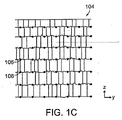
図1Dおよび1Eに示すように、例えば充填材料102は、創傷充填材料の特定の方向への収縮を可能とし、他の方向への収縮を妨げる(点線で示される)複数の安定化要素108を含む。本実施形態において安定化要素108は、プラスチックなどの適切な程度に剛性である、または半剛性である材料から形成された複数の安定化リブ、屈曲部、またはロッドを含む。リブを設けられた構造は、創傷の適切な閉鎖を促進するべく特定の軸に沿って選択的に収縮するように構成される。本実施形態に係る内部安定化要素108は、図1Dに示されるクロスハッチ構造を形成する。ただし、他の構成を用い得ることは理解いただけるであろう。「開かれた」状態において要素同士の間の間隔は、例えば1〜2cmの範囲である。安定化要素108は、図1Eの断面図に示されるように創傷充填材料内の異なる深さ位置に設けられてもよく、これによりz方向への収縮が妨げられる。いくつかの実施形態において、z軸安定化要素110を用いて、z軸方向への収縮を妨げられる。図1Eにおいて、z軸安定化要素110はリブ108から縦方向に延在する突出部である。他の実施形態において、ロッドまたはリブ構造の別個のz軸安定器を採用することが出来る。
As shown in FIGS. 1D and 1E, for example, the filling
特定の実施形態において器具100は、図1Eに示すように、充填材料102の外周周りに延在する周囲安定化要素111を含む。安定化要素111は、z方向への収縮を防ぎ、かつ、z−y平面およびz−x平面内での創傷充填材料の傾斜を妨げるべく、充填材料102を補強するリブ構造を含む。よって、創傷充填材料の好ましい実施形態は、負圧をかけられると、第2方向と相対的な少なくとも第1方向に選択的に収縮する。よって、例えば、創傷充填材料102は、長さ方向への収縮と比較して幅方向により速い速度で収縮し、高さ方向(創傷の深さ方向)には実質的に収縮しない。
In certain embodiments, the
いくつかの実施形態において組織固定化要素106は、周囲安定化要素111に含まれてもよく、充填材料102の周囲から突出する。この構成は、別個のメッシュまたはフィルムに固定化要素106を設けることの代替または追加として用いられてもよい。好ましくは周囲安定化要素111は、創傷充填材料102の拡大および収縮に合わせて必要に応じて拡大および収縮するよう構成される。よって好ましい実施形態において、安定化要素111は、x方向およびy方向(つまり充填材料102の周囲)に収縮および拡大出来るよう十分な可撓性を有しており、かつ、z方向への収縮または傾斜を妨げるべくz方向に(つまり充填材料の高さ方向に)十分な剛性を有している。
In some embodiments, the
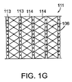
図1Gは、周囲安定化要素111の実施形態を示す正面図である。安定化要素111は、z方向への収縮を妨げるよう方向付けられた複数の安定化ロッド113を含む。ロッド113は、下方に位置する創傷充填材料の拡大および収縮に合わせて安定化要素111が創傷の縁周りに拡大および収縮出来るようにする可撓性材料114によって隔てられている。本実施形態において、組織固定化要素106は周囲安定化要素111に形成されており、図面から飛び出す方向に突出する。
FIG. 1G is a front view illustrating an embodiment of the
図2Aおよび図2Bは、本願発明に係る創傷充填材料の内骨格の一実施形態を示す。内骨格は、第1のセットのx−y安定化要素108a、および第2のセットのx−y安定化要素108bを含む。第1のセットのx−y安定化要素108a、および第2のセットのx−y安定化要素108bは互いに対応するもの同士が複数のz軸安定化要素110によって接続されている。充填材料102の収縮の際、x−y安定化要素108a、108bはそれぞれx−y方向に収縮可能であるが、z軸安定化要素110によってz方向への収縮が妨げられる。好ましい実施形態において、安定化要素は収縮の際に互いに対して関節動作できるように結合させることができる。当該構造における接合部109は、蝶番で動くようにされるか、システムの屈曲が可能であるように薄い厚さを有する。第1の軸、または水平方向の軸117(図4B参照)に沿った所望される圧縮が可能であるよう、接合部間の屈曲部は屈曲してもよい。器具が圧縮されるに従い、第2の軸、または長手方向の軸119に沿った拡大がいくらか起こり得る。枠材は、形状記憶特性を有していてもよく、当該特性と吸引力25とにより、組織に加えられる力の大きさが決まる。
2A and 2B show an embodiment of the endoskeleton of a wound filling material according to the present invention. The endoskeleton includes a first set of
図3Aおよび図3Bに示す他の実施形態において、内骨格は、収縮の際に充填材料102の傾斜を妨げるトラス安定器112を含む。トラス安定器112により、充填材料102が収縮する際に、上側のx−y安定器108aおよび下側のx−y安定器108bが互いに整列した状態が保たれる。いくつかの実施形態においてトラス安定器112は特定の方向への収縮を促進するべく、特定の方向に関して剛性であり、他の方向に関して比較的剛性ではない(例えばトラス安定器が曲げられ得る)。図3Cは、「x」形状のパターンを有するトラス安定器112を有する他の実施形態を示す。
In other embodiments shown in FIGS. 3A and 3B, the endoskeleton includes a
特定の実施形態に係る安定化内骨格は全体的または部分的に、形状記憶材料から形成される。変形された状態(一時的な形状)から自身の元の(恒久的な)形状へと戻ることが出来る様々な形状記憶材料を用いることが出来る。この形状の変化は、外部からの刺激または誘因要因により引き起こされ得る。一実施形態において、内骨格の元の、または「恒久的な」形状は、創傷閉鎖器具の「収縮した」構成であり、創傷の再接近をもたらす形状である。創傷閉鎖器具が初めに創傷の開きに挿入される際には、内骨格は変形させられた、または一時的な状態であり、その状態で創傷充填材料内に埋め込まれている。内骨格は選択的に元の、または「収縮した」状態に戻ることが出来、若しくは、器具を拡大させ組織と係合させられる。形状記憶型の内骨格の「収縮」力は、負圧源により引き起こされる真空力の代替または追加として用いられてもよい。特定の実施形態において、創傷閉鎖器具に対して負圧をかけることにより、内骨格の元の状態の復元を引き起こし得る。 The stabilized endoskeleton according to certain embodiments is formed in whole or in part from a shape memory material. Various shape memory materials can be used that can return from their deformed state (temporary shape) to their original (permanent) shape. This change in shape can be caused by external stimuli or incentive factors. In one embodiment, the original or “permanent” shape of the endoskeleton is the “contracted” configuration of the wound closure device and is the shape that results in the reapproach of the wound. When the wound closure device is first inserted into the wound opening, the endoskeleton is in a deformed or temporary state and is embedded in the wound filling material in that state. The endoskeleton can selectively return to its original or “contracted” state, or the instrument can be expanded and engaged with tissue. The “shrink” force of the shape memory type endoskeleton may be used as an alternative or addition to the vacuum force caused by the negative pressure source. In certain embodiments, applying negative pressure to the wound closure device may cause restoration of the original state of the endoskeleton.
図1Fは、一実施形態に係る創傷閉鎖器具100の底部を示す。本実施形態に係る器具100は、平滑な底面115を含む。用いられる材料は、Smith&Nephewから販売されるRenasys(登録商標)システムと関連して提供される生体適合性のフィルムであってよい。好ましい実施形態は、Renasys(登録商標)システムで提供されるゲージと共に用いられてもよい。底面115は、創傷閉鎖器具100とその下方に位置する組織との間の低摩擦の接触面となる。例えば腹部創傷の場合、下方に位置する組織とは、腸などの内臓を含みうる。平滑な底面115を用いることにより、下方に位置する組織からの干渉を受けず、かつ、下方に位置する組織に損傷を与えることなく、充填材料102は自由に収縮および拡大出来る。好ましい実施形態において底面115は、創傷部位から流体を除去するべく底面115を通過させ器具100内へと流入させる微細孔116(図1Fにおいては図示を分かりやすくするべくサイズに関して誇張して示されている)を含む。創傷閉鎖器具は、当該器具が摺動層上で収縮するよう独立した材料層上に挿入されてもよい。
FIG. 1F shows the bottom of a
いくつかの実施形態において、真空源からの複数の異なる力のレベルを器具100の複数の異なる領域へ方向付けるべく、微細孔116は、領域毎に異なるサイズを有するか、および/または、領域毎に異なる細孔密度を有する。同様に充填材料102は、真空源からの複数の異なる力の器具100の複数の異なる領域への分布を方向付けるべく、異なる内部細孔径、および/または細孔密度を用いて設計されてもよい。
In some embodiments, the
図4A、図4B、および図4Cは、創傷200を閉鎖するための器具100の利用を示す。図4Aに示すように創傷200は、創傷の開き201および創傷の縁203を含む。図4Bにおいて、組織把持表面104が創傷の縁203に接触するように、創傷閉鎖器具100は創傷の開き201内に配置される。特定の実施形態において創傷閉鎖器具100は、充填材料102を切り取るか引き剥がすことにより適切なサイズに形成され、その後、充填材料102の周囲に組織把持要素106を取り付ける。一実施形態において把持要素106は、2つの側面を有するバーブが形成されたメッシュを充填材料102へ取り付けることにより取り付けられる。ここで外向きの突起物が組織を把持するよう設計され、内向きの突起物は、メッシュを充填材料102へ固定するよう設計される。チューブ121は、充填材料102を負圧源へ接続する。充填材料102を含む創傷200の領域がシーリングドレープ(sealing drape)205により覆われてもよい。
4A, 4B, and 4C illustrate the use of the
図4Bの実施形態において充填材料102は、充填材料102に対し選択的に収縮する特性を付与する、(点線で示される)複数の内部安定化要素108を含む。安定化要素108は充填材料102の収縮、および結果として生じる、x方向およびy方向の創傷の縁203周りの組織の変位の制御を補助する。z方向の収縮を制御する、または妨げるべく安定化要素を追加して設けてもよい。図1Dに関連して上述したように、本実施形態に係る安定化要素108は、クロスハッチ構造を有する。
In the embodiment of FIG. 4B, the
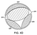
図4Cは、創傷閉鎖器具100へ負圧をかけた後の創傷200を示す。組織固定化要素106が創傷の縁203を把持し、充填材料102の収縮に応じた創傷の縁203の変位を引き起こす。図4Cに示されるように充填材料102は、創傷の縁203の組織を再接近させるようにx方向およびy方向に収縮する。図4Bおよび4Cの実施形態において、安定化要素108のクロスハッチ構造は、収縮の際の組織の変位の方向の制御を補助する。本実施形態において、組織の変位が最も大きくなるのは、創傷200の開き201の幅が最も大きい中央領域においてであり、この変位は、x方向に主に内向きに起こる。創傷の縁同士が互いに近い、中央領域から離れた位置(例えば、図4Aおよび4Bに示される創傷の最上部および最下部など)において、組織同士を再接近させるにはx方向の変位はより小さくてよい。一般的に創傷充填材料のy方向の内側への収縮は、望ましくない。事実、組織の再接近の際、創傷の縁のx方向の閉鎖に応じ、創傷200はy方向に長くなる。好ましい実施形態において、内部安定化要素108は創傷を再接近させるよう創傷充填材料の収縮を促す。例えば図4Cの実施形態において、充填材料が収縮する際、クロスハッチ構造の安定化要素108は、アコーディオン型のゲートのように互いに相対的に真っ直ぐになる。最も大きな変位は充填材料102の中央領域における、x方向の変位である。一般的に安定器108は、y方向の内側への収縮を妨げる。真っ直ぐになるにつれ安定器108は、y方向に創傷が細長い形状となり、適切な組織の再接近を促進する。複数の創傷閉鎖要素を組み合わせて充填される異なる形状を有する創傷220、240を図4Dおよび4Eに示す。図4Dにおいて要素222、224、226、228は、本例においては円形である創傷を実質的に充填出来るようなサイズに切り取られた複数の異なる形状を有する。負圧がかけられると要素は互いに協働し、所望される方向に創傷を閉鎖する。図4Eは、充填するための閉鎖要素242、244、246、248、250が用いられる長方形の創傷240を示す。各閉鎖要素の組織固定器は隣接する閉鎖要素同士を取り付けるのにも用いられ得る。中央の要素224、250に吸引力がかけられると、隣接する要素が中央の要素へと引き寄せられ、創傷を閉鎖する。
FIG. 4C shows the
創傷閉鎖器具200は創傷200の閉鎖および治癒を促進するべく、数日か数週間などの期間この状態のままであってよい。治癒のための期間の後、器具100は取り除かれ、場合によってはより小さなサイズの器具と交換される。本願発明に係る器具により創傷が十分に閉鎖されると、縫合により閉鎖され得る。
The
図5は、二段階の負圧創傷治療および負圧創傷閉鎖(NPWT/NPWC)器具300を示す。当該器具は、当技術分野で公知であるような、上方に位置する負圧創傷閉鎖器具100と接続される負圧ドレナージ/流体制御コンポーネント301を含む。創傷閉鎖器具100は、上述したものと実質的に同様の収縮可能な創傷充填材料102、および組織把持表面104を含む。チューブ121により器具300は、創傷閉鎖および創傷治療コンポーネントに負圧をかける単一のポンプへと接続される。特定の創傷への適用のために生じる必要性に応じて器具300は、交換可能な部品を含んでよい。一実施形態において器具300は腹部創傷に対して用いられ、縦隔および筋膜切開の創傷にも用いられ得る。
FIG. 5 shows a two-stage negative pressure wound treatment and negative pressure wound closure (NPWT / NPWC)
好ましい実施形態において充填材料102はNPWT/NPWC器具300全体の中で「摺動する」ことが出来る。充填材料102は創傷閉鎖コンポーネントと流体制御コンポーネントとの間の接触面において摺動面303を含む。摺動面は、加工された表面または独立した材料層を備えてよい。摺動面303は流体制御コンポーネントからの干渉を受けない創傷閉鎖コンポーネントの自由な収縮を促進する。下方に位置する流体制御コンポーネント301は特に、流体のみを制御し、「摺動」の速度を遅くするか、または「摺動」を妨げ得る粒状化を引き起こすことがないよう構成されてよい。
In a preferred embodiment, the
図6は、本願発明に係る組織固定システム400の好ましい実施形態の拡大図を示す。材料402の一側面には、創傷充填材料を把持するよう適合させられた第1のグループの固定化要素404が設けられている。第1固定化要素404は末端にフック形状406を有するなど充填材料を把持するように形状決めされてよい。組織に対し十分な引っ張り力を加えるべく材料402は一定の把持力で充填材料に取り付けられなければならないので、創傷充填材料からフックを取り除くには、組織に対して加えられる引っ張り力を超える一定の力レベルFを加える必要がある。同様に材料402によって把持される組織は、創傷充填材料とは異なる構造特性を有するので、組織を把持するよう適合させられた第2のグループの固定化要素410は、第1固定化要素とは異なる形状および把持力を有してよい。本実施形態において、返し412は、組織に挿入されると収縮し、かつ反対方向に引っ張られると一定の引っ張り力が組織に対して加わるよう拡大する左右対称の突起物414を有する。しかし、突起物またはコーン形状の固定化要素は、損傷を与えることなく人の力により返しを傷から引き抜くことが出来るようなリリース力を有する。
FIG. 6 shows an enlarged view of a preferred embodiment of a
図7は、異なる様々な創傷のサイズに対応するための引き剥がし設計または切り離し設計を有する創傷充填材料500の実施形態を示す。充填材料500は、閉鎖対象である創傷に適応するよう材料のサイズの調整を可能とする自然な切断線501、503、505を含む。材料500は、材料の1以上の部分502a、502b、502cを取り除き、材料のサイズを調整出来るよう切断線に沿って引き剥がされるか切り取られるように設計されている。所定の切断点において創傷充填材料内に複数の組織固定器506a、506b、506c、506dからなる複数のセットが埋め込まれており、当該セットは、部分502a、502b、502cが取り除かれることにより露出させられる。組織固定器506a、506b、506c、506dは、図1A〜図4Eに関連して上述したように、安定化内骨格構造と関連付けられていてよい。いくつかの実施形態において安定化内骨格構造は、充填材料500のサイズを調整する際に安定化構造の部分を取り除くための所定の切断点を含む。
FIG. 7 shows an embodiment of a
図8Aは、複数の異なるタイプの組織(T1、T2)に用いられる異なる組織固定器601、602、603、604を示す、組織把持表面の側面図である。それらのそれぞれに関し、真空閉鎖の際にかかる最大の力(F1)、および組織を損傷することなく組織から固定器を取り除くのに必要な力(F2)を含む固定器にかけられる力のプロファイルの例も併せて示す。一実施形態において組織固定器の特性は、組織閉鎖器具と周囲の組織との間の接触面に亘り異なる力プロファイルを提供するべく一様ではない。例えば上部の組織層T1に関しては、固定器601は、真皮中などのコラーゲン物質に取り付けられるよう設計されている。図8Aに示すように固定器601は、上部の組織層T1上に関して異なる力プロファイル(F1、F2)を有する。下部の組織層T2に関し、固定器602、603、604は皮下層の脂肪組織に取り付けされるよう設計されている。一般的にこの組織へ固定器を固定するには、小さい力プロファイルで済む。
FIG. 8A is a side view of a tissue grasping surface showing different tissue anchors 601, 602, 603, 604 used for a plurality of different types of tissue (T 1 , T 2 ). For each of them, a profile of the force applied to the fixator including the maximum force (F 1 ) applied during vacuum closure and the force required to remove the fixator from the tissue (F 2 ) without damaging the tissue This example is also shown. In one embodiment, the tissue anchor characteristics are not uniform to provide different force profiles across the interface between the tissue closure device and the surrounding tissue. For example, for the top of the tissue layer T 1, brace 601 is designed to be attached to the collagen material, such as the dermis. As shown in FIG. 8A, the
固定器の長さ、固定器の形状、把持特徴の構造、固定器に用いられる材料、固定器の相対的な可撓性/剛性、および固定器の間隔/密度など多くのパラメータによって、固定器の特性、および結果として生じるそれらの力プロファイルは異なるものと出来る。例えば図8Aにおいて、固定器601は、固定器602、603よりもはるかに長く、そして固定器602、603は固定器604よりも長い。図8Aは602、603、および604に示されるように固定器の密度を異ならせる例も示す。図8Bは、複数の異なるタイプの把持特徴として3つの例、返しが設けられた構造605、ずらしてフックが設けられた構造606、および、ずらして返しが設けられた構造607を示す。図8Cの拡大斜視図に示されるような固定化要素620などの他の適した把持特徴を用いてもよい。固定処理は、創傷充填材料または支持内骨格を組織に対し縫合することにより補強されてもよい。力プロファイルは、充填材料の細孔径、および/または細孔密度を変化させるなど、創傷充填材料内での真空力の分布を制御することによっても異ならせられる。
Depending on many parameters such as the length of the fixator, the shape of the fixator, the structure of the gripping features, the material used for the fixator, the relative flexibility / rigidity of the fixator, and the spacing / density of the fixator The characteristics of and the resulting force profiles can be different. For example, in FIG. 8A, the
本願発明に係る創傷閉鎖器具は、複数の異なるタイプの創傷(腹部、筋膜切開など)を閉鎖するためのキットとして提供されてもよい。組織把持表面は、コラーゲン、脂肪組織、および筋肉など創傷部位の組織の構造に応じて複数の異なるタイプの組織に合わせて最適化されてもよい。 The wound closure device according to the present invention may be provided as a kit for closing a plurality of different types of wounds (abdomen, fasciotomy, etc.). The tissue grasping surface may be optimized for several different types of tissue depending on the structure of the tissue at the wound site, such as collagen, adipose tissue, and muscle.
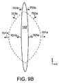
特定の実施形態において、創傷閉鎖器具の力プロファイルは、創傷の周囲に亘り一様ではない。図9Aは、例示的な実施形態に係る、創傷の周囲の複数の位置において創傷の縁に加えられる力プロファイル(f1)を示す。本実施形態において、最も大きなf1が加えられるのは、創傷の開きの幅が最も大きく、創傷を閉鎖する力が全体的またはほぼ全体的にx方向にかかる創傷充填材料102の中央領域においてである。創傷の最上部および最下部の領域においては、閉鎖する力(f1)ははるかに小さくなる。このような力プロファイルとなる一つの理由は、これらの領域において創傷の開きがはるかに小さく、組織を再接近させるのに必要な力がはるかに小さくて済むからである。またこれらの領域において加えられる内向きの力は、x方向およびy方向の成分を含む。よって、y方向への組織の内側の収縮を避けるには、より小さい力プロファイルが好ましい。図9Bに示されるように、創傷が閉鎖され、(点線で示される)当初の状態よりも(実線で示される)後期の状態へ治癒が進むにつれ、創傷はy方向に長くなる。よって、組織固定器701a、701bの変位は専らx方向であり閉鎖する力(f1)の方向への変位であり、組織固定器703a、703bの変位は、内側へのx方向(閉鎖する力の方向)、および外側へのy方向(閉鎖する力の反対方向)への変位である。よって、固定化要素と周囲の組織との間のより大きな「遊び」を提供するには、これらの領域においてf1は、より小さいのが好ましい。代替的に創傷閉鎖器具は、細長くはならず、長軸720に沿った長さが変わらないように構成される。
In certain embodiments, the force profile of the wound closure device is not uniform around the wound. FIG. 9A shows a force profile (f 1 ) applied to the wound edge at multiple locations around the wound, according to an exemplary embodiment. In this embodiment, the largest f 1 is added in the central region of the
創傷閉鎖器具の周囲の各部分において力プロファイルを異ならせるのは、組織固定器の間隔/密度、固定器のタイプ、固定器の長さなどを変化させるなど様々な方法により実現することが出来る。例えば図9Aおよび9Bにおいて、固定器703a、703bと比較し固定器701a、701bはより長く、組織内へとより深く貫通する。力プロファイルは、充填材料の細孔径および/または細孔密度を変化させるなど、創傷充填材料内の真空力分布を制御することにより異ならせることも出来る。
Different force profiles at different parts around the wound closure device can be achieved by various methods such as changing the spacing / density of the tissue fixator, the type of fixator, the length of the fixator, and the like. For example, in FIGS. 9A and 9B, compared to
一実施形態において、本願発明に係る創傷閉鎖器具を製造する方法は、剛性または半剛性材料からなる安定化内骨格を形成する工程と、当該内骨格上に収縮可能な創傷充填材料を形成する工程とを含む。安定化内骨格は、成形プロセスを用いて形成することが出来、一体型のユニット、または1以上の部材として成形することが出来る。当該1以上の部材は組立てられることにより内骨格を形成する。内骨格の複数の異なる部材は、複数の異なる方向に異なるレベルの剛性および可撓性を提供するべく、それぞれ異なる厚さ、および/または剛性度を有してもよい。内骨格は、適した接着剤、または他の接合プロセスを用いるなどにより部材を繋ぎ合わせることにより組立てられ得る。特定の実施形態において部材の少なくともいくつかは、関節動作できるように結合させた接合部を提供するべく組立てられる。好ましい実施形態において創傷充填材料は、適切に測量した成分(例えばポリウレタンフォームの場合、イソシアネート、ポリオール、触媒、界面活性剤、発泡剤など)を混ぜ合わせ、型内に反応混合物を注入し、当該材料を硬化させ型から取り出すことにより形成される。場合によっては材料は最終形状となるよう切り取られてもよい。好ましい実施形態において内骨格支持構造は組立てられ型内に配置され、創傷充填材料が内骨格周りに成形される。本願発明に係る創傷閉鎖器具に適した生分解性の発泡体製品、およびそのような発泡体を製造する方法の例は、Rolfesらによる米国特許公開出願第2009/0093550号に説明されている。当該特許公開出願の内容はその全体が、参照により本願に組み込まれる。 In one embodiment, a method of manufacturing a wound closure device according to the present invention includes forming a stabilized endoskeleton made of a rigid or semi-rigid material and forming a shrinkable wound filling material on the endoskeleton. Including. The stabilized endoskeleton can be formed using a molding process and can be molded as an integral unit or as one or more members. The one or more members are assembled to form an endoskeleton. The different members of the endoskeleton may have different thicknesses and / or stiffnesses to provide different levels of stiffness and flexibility in different directions. The endoskeleton can be assembled by joining the members, such as by using a suitable adhesive, or other joining process. In certain embodiments, at least some of the members are assembled to provide an articulated joint . In a preferred embodiment, the wound filling material mixes appropriately metered ingredients (for example, in the case of polyurethane foams, isocyanates, polyols, catalysts, surfactants, foaming agents, etc.), injects the reaction mixture into the mold, and the material Is formed by curing and removing from the mold. In some cases, the material may be cut to a final shape. In a preferred embodiment, the endoskeletal support structure is assembled and placed in a mold and a wound filler material is molded around the endoskeleton. Examples of biodegradable foam products suitable for wound closure devices according to the present invention and methods of making such foams are described in US Patent Application Publication No. 2009/0093550 by Rolles et al. The entire contents of the patent publication application are incorporated herein by reference.
図10は、本願発明の好ましい実施形態に係る創傷閉鎖器具を用いた手術手順800を実行する方法を示す。手術を行うべく患者の準備800が整った後、典型的には腹部である手術部位を露出させるべく切開820が行われる。手術が実行された後、閉鎖を行うための創傷の処理830を行う。周囲組織取り付け部材が器具の周囲面または外壁面に位置付けられた状態で、創傷閉鎖器具の適切なサイズおよび形状が選択840される。創傷に器具が挿入850され、組織取り付け要素が組織内へと挿入860される。その後、創傷の縁を閉鎖する力を加えるべく負圧が加えられる870。大きなサイズの創傷の場合など特定の適用によっては、最初の大きなサイズの器具が取り除かれた後、より小さなサイズの第2の閉鎖器具を配置880する必要がある。最後に、器具が取り除かれ890、典型的には縫合により創傷が閉鎖される。
FIG. 10 illustrates a method for performing a
特定の方法および装置に関連して本願発明を説明してきたが、当業者であれば本明細書で説明した特定の実施形態の他の同等の実施形態を思い付くであろう。説明は例示であり、本願発明の態様を限定するものとして解されるべきではない。同等の実施形態は、以下の特許請求項により包含される。 Although the present invention has been described with reference to particular methods and apparatus, those skilled in the art will envision other equivalent embodiments of the specific embodiments described herein. The description is illustrative and should not be construed as limiting aspects of the present invention. Equivalent embodiments are encompassed by the following claims.
Claims (36)
前記創傷充填材料が、y軸に沿った長さ寸法、x軸に沿った幅寸法、およびz軸に沿った高さ寸法を有しており、
前記創傷充填材料が、少なくとも1つの第1方向への収縮を可能とし、前記第2方向への収縮を妨げるための、網状構造の相互接続された複数の安定化要素を含む安定化構造を有しており、前記安定化構造が、前記高さ寸法の収縮を妨げ、且つ、x−y平面への前記創傷充填材料の収縮を制限し、
前記網状構造の相互接続された複数の安定化要素が、前記創傷充填材料が収縮する際に互いに対して関節動作できるように結合されている、負圧創傷閉鎖器具。 A wound filling material sized and shaped to accommodate the opening of a wound and selectively contracts at least along a first direction relative to a second direction when negative pressure is applied to the wound filling material A negative pressure wound closure device comprising a wound filling material configured to:
The wound filling material has a length dimension along the y-axis, a width dimension along the x-axis, and a height dimension along the z-axis;
The wound filling material has a stabilization structure that includes a plurality of interconnected stabilization elements to enable at least one contraction in a first direction and prevent contraction in the second direction. The stabilizing structure prevents shrinkage of the height dimension and limits shrinkage of the wound filler material to an xy plane;
A negative pressure wound closure device wherein a plurality of interconnected stabilizing elements of the network are operatively coupled to one another as the wound filler material contracts.
前記複数の組織固定器は前記フィルムから外方に突出する、請求項2に記載の負圧創傷閉鎖器具。 The tissue grasping surface comprises a film disposed on the surface of the wound filling material;
The negative pressure wound closure device according to claim 2, wherein the plurality of tissue anchors protrude outwardly from the film.
Applications Claiming Priority (3)
| Application Number | Priority Date | Filing Date | Title |
|---|---|---|---|
| US201161439525P | 2011-02-04 | 2011-02-04 | |
| US61/439,525 | 2011-02-04 | ||
| PCT/US2012/023754 WO2012106590A2 (en) | 2011-02-04 | 2012-02-03 | Negative pressure wound closure device |
Related Child Applications (1)
| Application Number | Title | Priority Date | Filing Date |
|---|---|---|---|
| JP2017111453A Division JP6470349B2 (en) | 2011-02-04 | 2017-06-06 | Negative pressure wound closure device |
Publications (3)
| Publication Number | Publication Date |
|---|---|
| JP2014511222A JP2014511222A (en) | 2014-05-15 |
| JP2014511222A5 JP2014511222A5 (en) | 2016-08-25 |
| JP6158096B2 true JP6158096B2 (en) | 2017-07-05 |
Family
ID=46603322
Family Applications (4)
| Application Number | Title | Priority Date | Filing Date |
|---|---|---|---|
| JP2013552670A Expired - Fee Related JP6158096B2 (en) | 2011-02-04 | 2012-02-03 | Negative pressure wound closure device |
| JP2017111453A Active JP6470349B2 (en) | 2011-02-04 | 2017-06-06 | Negative pressure wound closure device |
| JP2019006438A Active JP7063519B2 (en) | 2011-02-04 | 2019-01-17 | Negative pressure wound closure device |
| JP2022002498A Pending JP2022046774A (en) | 2011-02-04 | 2022-01-11 | Negative pressure wound closure device |
Family Applications After (3)
| Application Number | Title | Priority Date | Filing Date |
|---|---|---|---|
| JP2017111453A Active JP6470349B2 (en) | 2011-02-04 | 2017-06-06 | Negative pressure wound closure device |
| JP2019006438A Active JP7063519B2 (en) | 2011-02-04 | 2019-01-17 | Negative pressure wound closure device |
| JP2022002498A Pending JP2022046774A (en) | 2011-02-04 | 2022-01-11 | Negative pressure wound closure device |
Country Status (10)
| Country | Link |
|---|---|
| US (4) | US9226737B2 (en) |
| EP (2) | EP3932327A1 (en) |
| JP (4) | JP6158096B2 (en) |
| CN (2) | CN106974683B (en) |
| AU (5) | AU2012212070A1 (en) |
| CA (1) | CA2828964A1 (en) |
| MX (2) | MX358022B (en) |
| RU (2) | RU2612529C2 (en) |
| WO (1) | WO2012106590A2 (en) |
| ZA (1) | ZA201306619B (en) |
Families Citing this family (76)
| Publication number | Priority date | Publication date | Assignee | Title |
|---|---|---|---|---|
| US11298453B2 (en) | 2003-10-28 | 2022-04-12 | Smith & Nephew Plc | Apparatus and method for wound cleansing with actives |
| US10413644B2 (en) | 2004-04-27 | 2019-09-17 | Smith & Nephew Plc | Wound treatment apparatus and method |
| US8529548B2 (en) | 2004-04-27 | 2013-09-10 | Smith & Nephew Plc | Wound treatment apparatus and method |
| US9820888B2 (en) | 2006-09-26 | 2017-11-21 | Smith & Nephew, Inc. | Wound dressing |
| GB0808376D0 (en) | 2008-05-08 | 2008-06-18 | Bristol Myers Squibb Co | Wound dressing |
| GB0817796D0 (en) | 2008-09-29 | 2008-11-05 | Convatec Inc | wound dressing |
| GB201020236D0 (en) | 2010-11-30 | 2011-01-12 | Convatec Technologies Inc | A composition for detecting biofilms on viable tissues |
| ES2748519T3 (en) | 2010-12-08 | 2020-03-17 | Convatec Technologies Inc | Wound exudate system accessory |
| CA2819475C (en) | 2010-12-08 | 2019-02-12 | Convatec Technologies Inc. | Integrated system for assessing wound exudates |
| EP3932327A1 (en) | 2011-02-04 | 2022-01-05 | University Of Massachusetts | Negative pressure wound closure device |
| US9421132B2 (en) | 2011-02-04 | 2016-08-23 | University Of Massachusetts | Negative pressure wound closure device |
| CA2838058C (en) | 2011-06-07 | 2019-06-18 | Smith & Nephew Plc | Wound contacting members and methods |
| EP2734260A4 (en) * | 2011-07-19 | 2015-04-22 | Shieldheart Medtech Ab | Stabilizer, barrier disc and wound dressing comprising stabilizer, method for controlling the position of a wound dressing or barrier disc, and method for facilitating drainage from a wound dressing or barrier disc in negative pressure wound treatment |
| GB201115182D0 (en) | 2011-09-02 | 2011-10-19 | Trio Healthcare Ltd | Skin contact material |
| GB2497406A (en) | 2011-11-29 | 2013-06-12 | Webtec Converting Llc | Dressing with a perforated binder layer |
| GB201120693D0 (en) | 2011-12-01 | 2012-01-11 | Convatec Technologies Inc | Wound dressing for use in vacuum therapy |
| AU2013291693B2 (en) | 2012-05-22 | 2018-03-01 | Smith & Nephew Plc | Wound closure device |
| CA2874392A1 (en) | 2012-05-22 | 2013-11-28 | Smith & Nephew Plc | Apparatuses and methods for wound therapy |
| EP3470029A1 (en) | 2012-05-24 | 2019-04-17 | Smith & Nephew, Inc. | Devices for treating and closing wounds with negative pressure |
| BR112015000890A2 (en) | 2012-07-16 | 2017-06-27 | Smith & Nephew Inc | negative pressure wound closure device |
| CN104768474B (en) * | 2012-07-16 | 2018-10-19 | 马萨诸塞州大学 | Negative pressure wound closure device |
| CN105008611A (en) | 2012-12-20 | 2015-10-28 | 康沃特克科技公司 | Processing of chemically modified cellulosic fibres |
| DE102013004573A1 (en) * | 2013-03-11 | 2014-09-11 | Johnson & Johnson Medical Gmbh | Surgical implant |
| JP6407954B2 (en) * | 2013-03-13 | 2018-10-17 | スミス アンド ネフュー インコーポレイテッド | Negative pressure wound closure device and system and method of use in wound treatment with negative pressure |
| EP2968015B1 (en) | 2013-03-14 | 2018-05-16 | Smith & Nephew PLC | Compressible wound fillers and systems and methods of use in treating wounds with negative pressure |
| EP3677291B1 (en) | 2013-05-10 | 2024-01-03 | Smith & Nephew PLC | Fluidic connector for irrigation and aspiration of wounds |
| EP3021806B1 (en) | 2013-07-16 | 2018-01-31 | Smith & Nephew PLC | Apparatus for wound therapy |
| CA2926470C (en) | 2013-10-21 | 2023-03-14 | Smith & Nephew, Inc. | Negative pressure wound closure device |
| MX2016009477A (en) | 2014-01-21 | 2016-10-13 | Smith & Nephew | Collapsible dressing for negative pressure wound treatment. |
| CN106456376B (en) | 2014-01-21 | 2020-12-15 | 史密夫及内修公开有限公司 | Wound treatment device |
| US9943394B2 (en) * | 2014-02-24 | 2018-04-17 | Boston Scientific Scimed, Inc. | Hemostasis and closure methods utilizing mesh |
| WO2015172104A1 (en) * | 2014-05-09 | 2015-11-12 | Kci Licensing, Inc. | Debriding dressing for use with negative pressure and fluid instillation |
| EP3139878B1 (en) * | 2014-05-09 | 2017-09-13 | KCI Licensing, Inc. | Dressing with contracting layer for linear tissue sites |
| EP3157484B1 (en) | 2014-06-18 | 2020-02-26 | Smith & Nephew plc | Wound dressing |
| JP6751076B2 (en) * | 2014-08-11 | 2020-09-02 | ケーシーアイ ライセンシング インコーポレイテッド | Protease-regulated wound interface layer for use with negative pressure wound therapy |
| CN104188705B (en) * | 2014-09-11 | 2016-10-05 | 黄成� | Moulding of a kind of hemostasis |
| US11439539B2 (en) | 2015-04-29 | 2022-09-13 | University Of Massachusetts | Negative pressure wound closure device |
| WO2016188968A1 (en) * | 2015-05-26 | 2016-12-01 | Smith & Nephew Plc | Compressible negative pressure source and methods of use |
| WO2017053872A1 (en) * | 2015-09-25 | 2017-03-30 | Steven Craig Anderson | Apparatus and method for adhesion |
| US10575991B2 (en) | 2015-12-15 | 2020-03-03 | University Of Massachusetts | Negative pressure wound closure devices and methods |
| WO2018237206A2 (en) * | 2017-06-21 | 2018-12-27 | University Of Massachusetts | Negative pressure wound closure devices and methods |
| US10814049B2 (en) | 2015-12-15 | 2020-10-27 | University Of Massachusetts | Negative pressure wound closure devices and methods |
| US11471586B2 (en) | 2015-12-15 | 2022-10-18 | University Of Massachusetts | Negative pressure wound closure devices and methods |
| AU2017243601A1 (en) | 2016-03-30 | 2018-11-22 | Acib Gmbh | Detecting microbial infection in wounds |
| TW201800069A (en) | 2016-03-30 | 2018-01-01 | 康華特科技有限公司 | Detecting microbial infection in wounds |
| AU2017292876B2 (en) | 2016-07-08 | 2022-01-20 | Convatec Technologies Inc. | Fluid collection apparatus |
| AU2017292028B2 (en) | 2016-07-08 | 2023-03-02 | Convatec Technologies Inc. | Fluid flow sensing |
| BR112019000301A2 (en) | 2016-07-08 | 2019-04-16 | Convatec Technologies Inc. | flexible negative pressure system |
| US20190201250A1 (en) | 2016-08-30 | 2019-07-04 | Smith & Nephew, Inc. | Negative pressure wound closure device |
| EP4085884A1 (en) | 2016-08-30 | 2022-11-09 | Smith & Nephew, Inc. | Wound closure devices |
| EP3506865B1 (en) | 2016-08-30 | 2021-10-06 | Smith & Nephew plc | Systems for applying reduced pressure therapy |
| EP3518847B1 (en) | 2016-09-27 | 2023-03-01 | Smith & Nephew plc | Wound closure devices with dissolvable portions |
| EP3534856A1 (en) * | 2016-11-02 | 2019-09-11 | Smith & Nephew, Inc | Wound closure devices |
| EP3554573A1 (en) | 2016-12-16 | 2019-10-23 | Smith & Nephew PLC | Negative pressure wound closure device |
| CN106726146A (en) * | 2017-01-18 | 2017-05-31 | 柴家科 | For the negative pressure wound surface therapeutic system of Wound treating |
| CA3044955A1 (en) * | 2017-01-23 | 2018-07-26 | Medela Holding Ag | Porous wound dressing for use in negative-pressure therapy |
| CN110662516B (en) * | 2017-06-13 | 2022-02-22 | 史密夫及内修公开有限公司 | Wound closure devices and methods of use |
| WO2018229010A1 (en) * | 2017-06-13 | 2018-12-20 | Smith & Nephew Plc | Collapsible structure and method of use |
| US11724020B2 (en) | 2017-06-14 | 2023-08-15 | Smith & Nephew Plc | Collapsible sheet for wound closure and method of use |
| WO2018231878A1 (en) | 2017-06-14 | 2018-12-20 | Smith & Nephew, Inc. | Fluid removal management and control of wound closure in wound therapy |
| EP3638170B1 (en) | 2017-06-14 | 2024-03-13 | Smith & Nephew PLC | Collapsible structure for wound closure and method of use |
| WO2018231874A1 (en) | 2017-06-14 | 2018-12-20 | Smith & Nephew, Inc. | Control of wound closure and fluid removal management in wound therapy |
| WO2019020544A1 (en) | 2017-07-27 | 2019-01-31 | Smith & Nephew Plc | Customizable wound closure device and method of use |
| US11590030B2 (en) | 2017-08-07 | 2023-02-28 | Smith & Nephew Plc | Wound closure device with protective layer and method of use |
| WO2019042790A1 (en) | 2017-08-29 | 2019-03-07 | Smith & Nephew Plc | Systems and methods for monitoring wound closure |
| CA3077139A1 (en) * | 2017-10-06 | 2019-04-11 | Aroa Biosurgery Limited | Fluid drainage or delivery device for treatment site |
| RU182371U1 (en) * | 2018-01-31 | 2018-08-15 | федеральное государственное бюджетное образовательное учреждение высшего образования "Омский государственный медицинский университет" Министерства здравоохранения Российской Федерации (ФГБОУ ВО ОмГМУ Минздрава России) | Individual splint with support plane |
| WO2019157466A1 (en) | 2018-02-12 | 2019-08-15 | Healyx Labs, Inc. | Negative pressure wound therapy systems, devices, and methods |
| USD878609S1 (en) | 2018-04-09 | 2020-03-17 | Kci Licensing, Inc. | Compressive layer for abdominal wound dressing |
| US11040127B2 (en) * | 2018-04-09 | 2021-06-22 | Kci Licensing, Inc. | Abdominal dressing with mechanism for fascial closure |
| WO2019199798A1 (en) * | 2018-04-13 | 2019-10-17 | Kci Licensing, Inc. | Compression strain and negative pressure delivery indicator for a wound dressing |
| US11253401B2 (en) | 2018-08-03 | 2022-02-22 | Kci Licensing, Inc. | Wound therapy system with wound volume estimation |
| EP3840794B1 (en) | 2018-08-21 | 2023-10-11 | 3M Innovative Properties Company | System for utilizing pressure decay to determine available fluid capacity in a negative pressure dressing |
| US11771819B2 (en) | 2019-12-27 | 2023-10-03 | Convatec Limited | Low profile filter devices suitable for use in negative pressure wound therapy systems |
| US11331221B2 (en) | 2019-12-27 | 2022-05-17 | Convatec Limited | Negative pressure wound dressing |
| WO2023172751A1 (en) | 2022-03-10 | 2023-09-14 | University Of Massachusetts | Devices and methods of treating wounds |
Family Cites Families (349)
| Publication number | Priority date | Publication date | Assignee | Title |
|---|---|---|---|---|
| US3194239A (en) | 1963-01-16 | 1965-07-13 | Cornelius J P Sullivan | Suture provided with radiopaque free metal |
| US3789851A (en) | 1971-07-01 | 1974-02-05 | H Leveen | Wound splints |
| JPS5636960A (en) | 1979-08-31 | 1981-04-10 | Matsuda Ika Kogyo | Suturing gut for medical treatment |
| US4467805A (en) | 1982-08-25 | 1984-08-28 | Mamoru Fukuda | Skin closure stapling device for surgical procedures |
| DK149601C (en) | 1984-01-23 | 1987-02-02 | Coloplast As | PRESSURELY BANDAGE |
| US4815468A (en) | 1987-01-09 | 1989-03-28 | Annand David S | Sutureless closure |
| US5409472A (en) | 1989-08-03 | 1995-04-25 | Smith & Nephew Plc | Adhesive polymeric foam dressings |
| US5264218A (en) | 1989-10-25 | 1993-11-23 | C. R. Bard, Inc. | Modifiable, semi-permeable, wound dressing |
| US5860978A (en) | 1990-09-25 | 1999-01-19 | Innovasive Devices, Inc. | Methods and apparatus for preventing migration of sutures through transosseous tunnels |
| US7229959B1 (en) | 1990-11-27 | 2007-06-12 | The American National Red Cross | Supplemented fibrin matrix delivery systems |
| US5636643A (en) | 1991-11-14 | 1997-06-10 | Wake Forest University | Wound treatment employing reduced pressure |
| US7198046B1 (en) | 1991-11-14 | 2007-04-03 | Wake Forest University Health Sciences | Wound treatment employing reduced pressure |
| FR2691923B1 (en) | 1992-06-04 | 1994-09-09 | Europ Propulsion | Honeycomb structure in thermostructural composite material and its manufacturing process. |
| US5336219A (en) * | 1993-03-23 | 1994-08-09 | Medi-Flex Hospital Products, Inc. | Skin closure system |
| US5584859A (en) | 1993-10-12 | 1996-12-17 | Brotz; Gregory R. | Suture assembly |
| US5423857A (en) | 1993-11-02 | 1995-06-13 | Ethicon, Inc. | Three piece surgical staple |
| US5695777A (en) | 1994-05-10 | 1997-12-09 | Medtronic, Inc. | Absorptive wound dressing for wound healing promotion |
| DK0853950T3 (en) | 1994-08-22 | 2002-11-25 | Kinetic Concepts Inc | Wound drainage canisters |
| US5512041A (en) | 1994-10-07 | 1996-04-30 | Scott Health Care | Wound dressing for promoting moist wound healing |
| GB9523253D0 (en) | 1995-11-14 | 1996-01-17 | Mediscus Prod Ltd | Portable wound treatment apparatus |
| US6287322B1 (en) | 1995-12-07 | 2001-09-11 | Loma Linda University Medical Center | Tissue opening locator and everter and method |
| US7771402B2 (en) | 1996-07-11 | 2010-08-10 | PulseCare Medical | Wound irrigation containment arrangement |
| US5960497A (en) | 1997-08-22 | 1999-10-05 | Kci-Rik Acquisition, Corp. | Pressure relieving pad with graduated pillars |
| JP4129296B2 (en) | 1997-04-14 | 2008-08-06 | バクスター インターナショナル インコーポレーテッド | Fluid applicator that dispenses a measured volume using controlled suction |
| US7214202B1 (en) | 1997-07-28 | 2007-05-08 | Kci Licensing, Inc. | Therapeutic apparatus for treating ulcers |
| US6080168A (en) | 1997-08-28 | 2000-06-27 | Levin; John M. | Compression pad for laparoscopic/thorascopic surgery |
| GB9719520D0 (en) | 1997-09-12 | 1997-11-19 | Kci Medical Ltd | Surgical drape and suction heads for wound treatment |
| GB9822341D0 (en) | 1998-10-13 | 1998-12-09 | Kci Medical Ltd | Negative pressure therapy using wall suction |
| US6767334B1 (en) | 1998-12-23 | 2004-07-27 | Kci Licensing, Inc. | Method and apparatus for wound treatment |
| DE19901134C2 (en) | 1999-01-14 | 2002-11-21 | Wilhelm Fleischmann | dressing material |
| US6086591A (en) | 1999-01-29 | 2000-07-11 | Smith & Nephew, Inc. | Soft tissue anchor |
| DE60036863T2 (en) | 1999-03-25 | 2008-07-31 | Metabolix, Inc., Cambridge | Medical devices and uses of polyhydroxyalkanoate polymers |
| EP1726276B2 (en) | 1999-04-02 | 2015-10-21 | KCI Licensing, Inc. | Vacuum assisted closure system with heating and cooling provision |
| IL145629A0 (en) | 1999-04-02 | 2002-06-30 | Kinetic Concepts Inc | Vacuum assisted closute system with provision for introduction of agent |
| US6994702B1 (en) | 1999-04-06 | 2006-02-07 | Kci Licensing, Inc. | Vacuum assisted closure pad with adaptation for phototherapy |
| US6695823B1 (en) | 1999-04-09 | 2004-02-24 | Kci Licensing, Inc. | Wound therapy device |
| GB9909301D0 (en) | 1999-04-22 | 1999-06-16 | Kci Medical Ltd | Wound treatment apparatus employing reduced pressure |
| US6991643B2 (en) * | 2000-12-20 | 2006-01-31 | Usgi Medical Inc. | Multi-barbed device for retaining tissue in apposition and methods of use |
| GB9926538D0 (en) * | 1999-11-09 | 2000-01-12 | Kci Medical Ltd | Multi-lumen connector |
| FR2801188B1 (en) | 1999-11-22 | 2002-11-08 | Didier Detour | DEVICE FOR THE NON-TRAUMATIC CLOSURE, WITHOUT SUTURE, OF THE OPEN EDGES OF A WOUND OF THE MAMMALIAN SKIN |
| US7153312B1 (en) | 1999-12-02 | 2006-12-26 | Smith & Nephew Inc. | Closure device and method for tissue repair |
| US6794554B2 (en) | 2000-02-01 | 2004-09-21 | Ferris Pharmaceuticals, Inc. | Wound packing material |
| US6566575B1 (en) | 2000-02-15 | 2003-05-20 | 3M Innovative Properties Company | Patterned absorbent article for wound dressing |
| US6977323B1 (en) | 2000-02-17 | 2005-12-20 | 3M Innovative Properties Company | Foam-on-film medical articles |
| US6548727B1 (en) | 2000-02-17 | 2003-04-15 | 3M Innovative Properties Company | Foam/film composite medical articles |
| US6712830B2 (en) | 2000-03-15 | 2004-03-30 | Esplin Medical Inventions, L.L.C. | Soft tissue anchor |
| GB0011202D0 (en) | 2000-05-09 | 2000-06-28 | Kci Licensing Inc | Abdominal wound dressing |
| US7156862B2 (en) | 2000-05-19 | 2007-01-02 | Coapt Systems, Inc. | Multi-point tension distribution system device and method of tissue approximation using that device to improve wound healing |
| BRPI0110976B8 (en) | 2000-05-19 | 2021-06-22 | Microaire Surgical Instr Llc | implantable tissue approximation device. |
| US7172615B2 (en) | 2000-05-19 | 2007-02-06 | Coapt Systems, Inc. | Remotely anchored tissue fixation device |
| US6645226B1 (en) | 2000-05-19 | 2003-11-11 | Coapt Systems, Inc. | Multi-point tension distribution system device and method of tissue approximation using that device to improve wound healing |
| US6485503B2 (en) | 2000-05-19 | 2002-11-26 | Coapt Systems, Inc. | Multi-point tissue tension distribution device, a brow and face lift variation, and a method of tissue approximation using the device |
| US20050119694A1 (en) | 2000-05-19 | 2005-06-02 | Jacobs Daniel I. | Remotely anchored tissue fixation device and method |
| US20040010275A1 (en) | 2000-05-19 | 2004-01-15 | Daniel Jacobs | Multi-point tissue tension distribution device and method, a custom-fittable variation |
| DE60130993T3 (en) | 2000-07-18 | 2013-08-29 | Coloplast A/S | WOUND DRESSING |
| US6767356B2 (en) | 2000-09-01 | 2004-07-27 | Angiolink Corporation | Advanced wound site management systems and methods |
| US7066182B1 (en) | 2000-09-27 | 2006-06-27 | 3M Innovative Properties Company | Conformable adhesive wound closures |
| US20060205995A1 (en) | 2000-10-12 | 2006-09-14 | Gyne Ideas Limited | Apparatus and method for treating female urinary incontinence |
| GB0025068D0 (en) | 2000-10-12 | 2000-11-29 | Browning Healthcare Ltd | Apparatus and method for treating female urinary incontinence |
| US6685681B2 (en) | 2000-11-29 | 2004-02-03 | Hill-Rom Services, Inc. | Vacuum therapy and cleansing dressing for wounds |
| US6855135B2 (en) | 2000-11-29 | 2005-02-15 | Hill-Rom Services, Inc. | Vacuum therapy and cleansing dressing for wounds |
| US7700819B2 (en) | 2001-02-16 | 2010-04-20 | Kci Licensing, Inc. | Biocompatible wound dressing |
| US7070584B2 (en) | 2001-02-20 | 2006-07-04 | Kci Licensing, Inc. | Biocompatible wound dressing |
| US7645269B2 (en) | 2001-04-30 | 2010-01-12 | Kci Licensing, Inc. | Gradient wound treatment system and method |
| WO2002091999A2 (en) | 2001-05-09 | 2002-11-21 | Geron Corporation | Treatment for wounds |
| AU2002315027A1 (en) | 2001-05-15 | 2002-11-25 | Children's Medical Center Corporation | Methods and apparatus for application of micro-mechanical forces to tissues |
| EP2572674A3 (en) | 2001-07-06 | 2013-08-07 | Syntach AG | Implantable blood pressure regulator device |
| ES2252505T3 (en) | 2001-07-13 | 2006-05-16 | Janssen Pharmaceutica N.V. | CARDIOVASCULAR SAFETY TESTS. |
| KR20040034670A (en) | 2001-08-03 | 2004-04-28 | 아사히 가세이 라이프 앤드 리빙 가부시키가이샤 | Color masking component for use with feminine sanitary pad and the like |
| US7004915B2 (en) | 2001-08-24 | 2006-02-28 | Kci Licensing, Inc. | Negative pressure assisted tissue treatment system |
| US6787682B2 (en) | 2001-11-05 | 2004-09-07 | Hollister Incorporated | Absorbent foam wound dressing |
| US20050048035A1 (en) | 2001-12-07 | 2005-03-03 | Fraser John K. | Methods of using regenerative cells in the treatment of stroke and related diseases and disorders |
| US6958432B2 (en) | 2001-12-14 | 2005-10-25 | Kimberly-Clark Worldwide, Inc. | Disposable absorbent article |
| US6726668B2 (en) | 2001-12-14 | 2004-04-27 | Kimberly-Clark Worldwide, Inc. | Disposable absorbent article |
| US20030120249A1 (en) | 2001-12-20 | 2003-06-26 | Wulz Andrea Susan | Absorbent article having an insert providing for improved fluid distribution |
| CA2468309A1 (en) | 2001-12-26 | 2003-07-17 | Robert Petrosenko | Wound vacuum therapy dressing kit |
| US6645330B2 (en) | 2002-01-03 | 2003-11-11 | Paragon Trade Brands, Inc. | Method of making disposable absorbent article having graphics using ultrasonic thermal imaging |
| DE10209122B4 (en) | 2002-03-01 | 2006-04-13 | Fleischmann, Wilhelm, Dr.med. | Instrument for tissue dilation of the skin |
| US8241308B2 (en) | 2002-04-24 | 2012-08-14 | Boston Scientific Scimed, Inc. | Tissue fastening devices and processes that promote tissue adhesion |
| AU2003276105A1 (en) | 2002-06-14 | 2003-12-31 | Loma Linda University Medical Center | Vascular wound closure device and method |
| GB2389794A (en) | 2002-06-19 | 2003-12-24 | Johnson & Johnson Medical Ltd | Wound dressing with variable shape |
| US7164360B2 (en) | 2002-08-14 | 2007-01-16 | Mark Schiebler | Multi-use linkage device |
| US7413571B2 (en) * | 2002-08-21 | 2008-08-19 | Kci Licensing, Inc. | Flexible medical closure screen and method |
| US8062331B2 (en) | 2002-08-21 | 2011-11-22 | Kci Licensing, Inc. | Internal and external medical closure screen systems and methods |
| US7351250B2 (en) * | 2002-08-21 | 2008-04-01 | Kci Licensing, Inc. | Circumferential medical closure device and method |
| US7896856B2 (en) | 2002-08-21 | 2011-03-01 | Robert Petrosenko | Wound packing for preventing wound closure |
| US7381211B2 (en) | 2002-08-21 | 2008-06-03 | Kci Licensing, Inc. | Medical closure screen device and method |
| US7846141B2 (en) | 2002-09-03 | 2010-12-07 | Bluesky Medical Group Incorporated | Reduced pressure treatment system |
| US7815616B2 (en) | 2002-09-16 | 2010-10-19 | Boehringer Technologies, L.P. | Device for treating a wound |
| US7625362B2 (en) | 2003-09-16 | 2009-12-01 | Boehringer Technologies, L.P. | Apparatus and method for suction-assisted wound healing |
| US7189238B2 (en) | 2002-09-25 | 2007-03-13 | Linvatec Corporation | Soft tissue anchor |
| GB0224986D0 (en) | 2002-10-28 | 2002-12-04 | Smith & Nephew | Apparatus |
| US7367342B2 (en) | 2002-12-02 | 2008-05-06 | Life Support Technologies, Inc. | Wound management systems and methods for using the same |
| US7976519B2 (en) | 2002-12-31 | 2011-07-12 | Kci Licensing, Inc. | Externally-applied patient interface system and method |
| US6951553B2 (en) | 2002-12-31 | 2005-10-04 | Kci Licensing, Inc | Tissue closure treatment system and method with externally-applied patient interface |
| JP4002847B2 (en) | 2003-01-31 | 2007-11-07 | 松下電器産業株式会社 | Level conversion circuit with automatic delay adjustment function |
| US6838589B2 (en) | 2003-02-19 | 2005-01-04 | 3M Innovative Properties Company | Conformable wound dressing |
| US20070255167A1 (en) | 2004-03-01 | 2007-11-01 | Wolfe Tory Medical, Inc. | Apparatus for monitoring intra-abdominal pressure |
| WO2005004928A2 (en) | 2003-04-04 | 2005-01-20 | W.R. Grace & Co.-Conn. | Porous particulate collagen sponges |
| US20050020899A1 (en) | 2003-07-25 | 2005-01-27 | Rubicor Medical, Inc. | Post-biopsy cavity treatmetn implants and methods |
| US7942866B2 (en) | 2003-08-28 | 2011-05-17 | Boehringer Technologies, L.P. | Device for treating a wound |
| US7361184B2 (en) | 2003-09-08 | 2008-04-22 | Joshi Ashok V | Device and method for wound therapy |
| NL1025938C2 (en) | 2003-09-17 | 2005-03-18 | Broockeville Corp N V | Wound drainage device. |
| GB0325129D0 (en) * | 2003-10-28 | 2003-12-03 | Smith & Nephew | Apparatus in situ |
| GB0325130D0 (en) | 2003-10-28 | 2003-12-03 | Smith & Nephew | Apparatus with scaffold |
| GB0325120D0 (en) | 2003-10-28 | 2003-12-03 | Smith & Nephew | Apparatus with actives |
| GB0518804D0 (en) | 2005-09-15 | 2005-10-26 | Smith & Nephew | Exudialysis tissue cleanser |
| US7252870B2 (en) | 2003-12-31 | 2007-08-07 | Kimberly-Clark Worldwide, Inc. | Nonwovens having reduced Poisson ratio |
| US7128735B2 (en) | 2004-01-02 | 2006-10-31 | Richard Scott Weston | Reduced pressure wound treatment appliance |
| US20050222613A1 (en) | 2004-02-05 | 2005-10-06 | Edwin Ryan | Wound closure device and method for vitrectomy |
| GB0403969D0 (en) | 2004-02-24 | 2004-03-31 | Huntleigh Technology Plc | Tissue treatment device |
| US8100887B2 (en) | 2004-03-09 | 2012-01-24 | Bluesky Medical Group Incorporated | Enclosure-based reduced pressure treatment system |
| US7754937B2 (en) | 2004-03-18 | 2010-07-13 | Boehringer Technologies, L.P. | Wound packing material for use with suction |
| US7909805B2 (en) | 2004-04-05 | 2011-03-22 | Bluesky Medical Group Incorporated | Flexible reduced pressure treatment appliance |
| US7776028B2 (en) | 2004-04-05 | 2010-08-17 | Bluesky Medical Group Incorporated | Adjustable overlay reduced pressure wound treatment system |
| US8062272B2 (en) | 2004-05-21 | 2011-11-22 | Bluesky Medical Group Incorporated | Flexible reduced pressure treatment appliance |
| US7708724B2 (en) | 2004-04-05 | 2010-05-04 | Blue Sky Medical Group Incorporated | Reduced pressure wound cupping treatment system |
| US7951124B2 (en) | 2004-04-13 | 2011-05-31 | Boehringer Technologies, Lp | Growth stimulating wound dressing with improved contact surfaces |
| GB0508528D0 (en) | 2005-04-27 | 2005-06-01 | Smith & Nephew | SAI with macrostress |
| GB0424046D0 (en) | 2004-10-29 | 2004-12-01 | Smith & Nephew | Apparatus |
| CA2567278A1 (en) | 2004-05-17 | 2005-12-08 | Applied Tissue Technologies, Llc | Wound chamber with remote access portal |
| US20060020269A1 (en) | 2004-07-20 | 2006-01-26 | Eric Cheng | Device to aid in stone removal and laser lithotripsy |
| US7364145B2 (en) * | 2004-09-08 | 2008-04-29 | Equipment Solutions, Inc | High stiffness flexure |
| US7455681B2 (en) | 2004-09-13 | 2008-11-25 | Wound Care Technologies, Llc | Wound closure product |
| US8491503B2 (en) | 2004-09-29 | 2013-07-23 | Covidien Lp | Intrauterine pressure catheter interface cable system |
| US8790632B2 (en) | 2004-10-07 | 2014-07-29 | Actamax Surgical Materials, Llc | Polymer-based tissue-adhesive form medical use |
| JP5178198B2 (en) | 2004-10-11 | 2013-04-10 | アブビサー メディカル リミテッド ライアビリティ カンパニー | Apparatus and method for intraperitoneal pressure monitoring |
| US9358318B2 (en) | 2004-10-20 | 2016-06-07 | Ethicon, Inc. | Method of making a reinforced absorbable multilayered hemostatic wound dressing |
| US20060257457A1 (en) | 2004-10-20 | 2006-11-16 | Gorman Anne J | Method for making a reinforced absorbable multilayered hemostatic wound dressing |
| US7315183B2 (en) | 2004-11-22 | 2008-01-01 | Texas Instruments Incorporated | Single-supply voltage translator input having low supply current |
| USD544092S1 (en) | 2004-12-03 | 2007-06-05 | Kci Licensing, Inc. | Wearable negative pressure wound care appliance |
| JP4560415B2 (en) | 2005-01-20 | 2010-10-13 | ユニ・チャーム株式会社 | Absorbent articles |
| US7722528B2 (en) | 2005-02-04 | 2010-05-25 | Ams Research Corporation | Surgical implants and related methods and systems |
| GB2423019A (en) | 2005-02-09 | 2006-08-16 | Ind Ltd Ak | Wound dressing and wound treatment system including the wound dressing |
| DE102005007016A1 (en) | 2005-02-15 | 2006-08-24 | Fleischmann, Wilhelm, Dr.med. | Device for the treatment of wounds |
| US20060259074A1 (en) | 2005-02-22 | 2006-11-16 | Brian Kelleher | Methods and devices for anchoring to soft tissue |
| WO2006110197A2 (en) * | 2005-03-03 | 2006-10-19 | Icon Medical Corp. | Polymer biodegradable medical device |
| US7438705B2 (en) | 2005-07-14 | 2008-10-21 | Boehringer Technologies, L.P. | System for treating a wound with suction and method detecting loss of suction |
| US20110077605A1 (en) | 2005-07-14 | 2011-03-31 | Boehringer Technologies, L.P. | Pump system for negative pressure wound therapy |
| US7857806B2 (en) | 2005-07-14 | 2010-12-28 | Boehringer Technologies, L.P. | Pump system for negative pressure wound therapy |
| US20070027414A1 (en) | 2005-07-28 | 2007-02-01 | Integra Lifesciences Corporation | Laminar construction negative pressure wound dressing including bioabsorbable material |
| US20070032755A1 (en) | 2005-08-02 | 2007-02-08 | Medica-Rents Co., Ltd. | Method and apparatus for treating a wound |
| US7608066B2 (en) | 2005-08-08 | 2009-10-27 | Innovative Therapies, Inc. | Wound irrigation device pressure monitoring and control system |
| JP2009509570A (en) | 2005-09-07 | 2009-03-12 | タイコ ヘルスケア グループ リミテッド パートナーシップ | Self-contained wound care device |
| CA2619925A1 (en) | 2005-09-07 | 2007-03-15 | Tyco Healthcare Group Lp | Wound dressing with vacuum reservoir |
| US7569742B2 (en) | 2005-09-07 | 2009-08-04 | Tyco Healthcare Group Lp | Self contained wound dressing with micropump |
| WO2007044510A1 (en) | 2005-10-05 | 2007-04-19 | Loma Linda University Medical Center | Vascular wound closure device and method |
| DK2010245T3 (en) | 2005-11-21 | 2016-01-18 | Joshua David Smith | WOUND CARE SYSTEM |
| US7605299B2 (en) | 2005-12-23 | 2009-10-20 | Biosara Corporation | Wound guard bandage |
| US20100081983A1 (en) | 2005-12-23 | 2010-04-01 | Biosara Corporation | Wound guard bandage |
| EP1986718B1 (en) | 2006-02-06 | 2015-10-28 | KCI Licensing, Inc. | Systems for improved connection to wound dressings in conjunction with reduced pressure wound treatment systems |
| JP5263882B2 (en) | 2006-02-07 | 2013-08-14 | コビディエン・リミテッド・パートナーシップ | Surgical wound dressing |
| AU2007224199B2 (en) | 2006-03-01 | 2013-09-12 | Boss Instruments, Ltd. | Surgical retractor frame system |
| EP2004070A4 (en) * | 2006-04-13 | 2015-07-22 | Kci Licensing Inc | Medical closure screen installation systems and methods |
| US20100028407A1 (en) | 2006-04-27 | 2010-02-04 | University Of Louisville Research Foundation, Inc. | Layered bio-adhesive compositions and uses thereof |
| US7779625B2 (en) | 2006-05-11 | 2010-08-24 | Kalypto Medical, Inc. | Device and method for wound therapy |
| US7615036B2 (en) | 2006-05-11 | 2009-11-10 | Kalypto Medical, Inc. | Device and method for wound therapy |
| US7837706B2 (en) | 2006-05-31 | 2010-11-23 | Boston Scientific Scimed, Inc. | Tissue attachment device, system, and method |
| WO2007142688A1 (en) | 2006-06-02 | 2007-12-13 | Bengtson Bradley P | Assemblies, systems, and methods for vacuum assisted internal drainage during wound healing |
| WO2007143179A2 (en) | 2006-06-02 | 2007-12-13 | Bengtson Bradley P | Assemblies, systems, and methods for vacuum assisted internal drainage during wound healing |
| US8551075B2 (en) | 2006-06-02 | 2013-10-08 | Kci Medical Resources | Assemblies, systems, and methods for vacuum assisted internal drainage during wound healing |
| EP2059204A4 (en) * | 2006-07-07 | 2010-12-01 | Boehringer Technologies Lp | Growth stimulating wound dressing with improved contact surfaces |
| US20080041401A1 (en) | 2006-08-15 | 2008-02-21 | Casola Robert P | Computer adjusted pressure wound care devices, systems & methods |
| US7491541B2 (en) | 2006-09-21 | 2009-02-17 | Kci Licensing, Inc. | Method for quantitation of collagen in tissue |
| US8680360B2 (en) | 2006-09-26 | 2014-03-25 | Smith & Nephew Inc. | Lattice dressing |
| GB0903032D0 (en) | 2009-02-24 | 2009-04-08 | Smith & Nephew | Drapeable wound dressing |
| US9820888B2 (en) | 2006-09-26 | 2017-11-21 | Smith & Nephew, Inc. | Wound dressing |
| EP2081629A4 (en) | 2006-09-28 | 2014-06-25 | Puricore Inc | Apparatus and method for wound, cavity, and bone treatment |
| BRPI0715320A2 (en) | 2006-10-13 | 2013-07-09 | Kci Licensing Inc | manually activated reduced pressure treatment system, activating method of a reduced pressure treatment pump and low profile reduced pressure treatment system |
| KR100788356B1 (en) | 2006-10-26 | 2008-01-02 | 동부일렉트로닉스 주식회사 | Level shifter having a single voltage source and capable of shifting between wide difference of voltage levels |
| US8353931B2 (en) | 2006-11-02 | 2013-01-15 | Covidien Lp | Long term bioabsorbable barbed sutures |
| US7931774B2 (en) | 2006-11-06 | 2011-04-26 | 3M Innovative Properties Company | Acrylic adhesives containing an amine plasticizer |
| US8030534B2 (en) | 2006-11-28 | 2011-10-04 | Boehringer Technologies, L.P. | Tunnel dressing for use with negative pressure wound therapy system |
| CA2669039A1 (en) | 2006-11-30 | 2008-06-05 | Medela Holding Ag | Device for treating wounds |
| RU62504U1 (en) * | 2006-12-07 | 2007-04-27 | Юрий Павлович Савченко | MEDIUM DRAINING DEVICE |
| WO2008104609A1 (en) | 2007-03-01 | 2008-09-04 | Coloplast A/S | Pressure-distributing elements for use with negative pressure therapy |
| US8057446B2 (en) | 2007-05-01 | 2011-11-15 | The Brigham And Women's Hospital, Inc. | Wound healing device |
| US8057447B2 (en) | 2007-05-10 | 2011-11-15 | Kci Licensing Inc. | Reduced pressure wound dressing having a wound contact surface with columnar protrusions |
| US8062315B2 (en) | 2007-05-17 | 2011-11-22 | Portaero, Inc. | Variable parietal/visceral pleural coupling |
| WO2008154158A2 (en) | 2007-05-24 | 2008-12-18 | Applied Tissue Technologies Llc | Woundtreatment device employing negative pressure |
| US7858835B2 (en) | 2007-06-27 | 2010-12-28 | Tyco Healthcare Group Lp | Foam control for synthetic adhesive/sealant |
| GB0715211D0 (en) | 2007-08-06 | 2007-09-12 | Smith & Nephew | Apparatus |
| USD602583S1 (en) | 2007-07-02 | 2009-10-20 | Smith & Nephew Plc | Device for applying negative pressure to a wound |
| GB0712737D0 (en) | 2007-07-02 | 2007-08-08 | Smith & Nephew | Apparatus |
| GB0712736D0 (en) | 2007-07-02 | 2007-08-08 | Smith & Nephew | Apparatus |
| GB0715259D0 (en) | 2007-08-06 | 2007-09-12 | Smith & Nephew | Canister status determination |
| GB0712757D0 (en) | 2007-07-02 | 2007-08-08 | Smith & Nephew | Pressure control |
| IN2010KN00792A (en) | 2007-08-03 | 2015-08-28 | Nicast Ltd | |
| CA2695728A1 (en) | 2007-08-06 | 2009-02-12 | Ohio Medical Corporation | Wound treatment system and suction regulator for use therewith |
| CN101112326A (en) | 2007-09-05 | 2008-01-30 | 李旭辉 | Skin wound stitching instrument |
| US20090099519A1 (en) | 2007-09-07 | 2009-04-16 | Albert Einstein Healthcare Network | Advanced abdominal dressing for the treatment of the postoperative hypothermic patients with an open abdomen |
| US9023001B2 (en) | 2007-09-12 | 2015-05-05 | Heal-Ex, Llc | Systems and methods for providing a debriding wound vacuum |
| US20090069904A1 (en) | 2007-09-12 | 2009-03-12 | Applied Medical Research | Biomaterial including micropores |
| US8197506B2 (en) | 2007-09-14 | 2012-06-12 | Kenneth Burke | Wound closing device |
| JP5474798B2 (en) | 2007-09-19 | 2014-04-16 | サーモディクス,インコーポレイティド | Biocompatible foams, systems and methods |
| EP3590480B1 (en) | 2007-10-11 | 2023-05-03 | 3M Innovative Properties Company | Closed incision negative pressure wound therapy device |
| US8746662B2 (en) | 2007-10-23 | 2014-06-10 | Elisna S.A.R.L. | Foam spring for pillows, cushions, mattresses or the like and method for manufacturing such a foam spring |
| CA2703942A1 (en) | 2007-10-23 | 2009-04-30 | Boehringer Technologies, L.P. | Thin film wound cover, suction assisted wound treatment system using the same, method of using the thin film wound cover and method of making the same |
| US9408755B2 (en) | 2007-11-13 | 2016-08-09 | Medela Holding Ag | Wound drainage dressing |
| US9060842B2 (en) * | 2007-11-19 | 2015-06-23 | Massachusettes Institute Of Technology | Adhesive articles |
| GB0722820D0 (en) | 2007-11-21 | 2008-01-02 | Smith & Nephew | Vacuum assisted wound dressing |
| HUE041864T2 (en) | 2007-11-21 | 2019-06-28 | Smith & Nephew | Wound dressing |
| AU2008327660B2 (en) | 2007-11-21 | 2014-02-13 | Smith & Nephew Plc | Wound dressing |
| GB0723872D0 (en) | 2007-12-06 | 2008-01-16 | Smith & Nephew | Apparatus for topical negative pressure therapy |
| US20130096518A1 (en) | 2007-12-06 | 2013-04-18 | Smith & Nephew Plc | Wound filling apparatuses and methods |
| GB0723876D0 (en) | 2007-12-06 | 2008-01-16 | Smith & Nephew | Apparatus and method for topical negative pressure therapy |
| GB0724044D0 (en) | 2007-12-08 | 2008-01-16 | Smith & Nephew | Wound packing members |
| US8273105B2 (en) | 2008-02-20 | 2012-09-25 | Tyco Healthcare Group Lp | Compound barb medical device and method |
| WO2009105761A2 (en) | 2008-02-22 | 2009-08-27 | Celonova Biosciences, Inc. | Multi-functional wound dressing matrices and related methods |
| US20090227938A1 (en) | 2008-03-05 | 2009-09-10 | Insitu Therapeutics, Inc. | Wound Closure Devices, Methods of Use, and Kits |
| US8449508B2 (en) | 2008-03-05 | 2013-05-28 | Kci Licensing, Inc. | Dressing and method for applying reduced pressure to and collecting and storing fluid from a tissue site |
| WO2009112062A1 (en) | 2008-03-11 | 2009-09-17 | Umc Utrecht Holding B.V. | Device and method for transseptal puncturing |
| AU2009223037A1 (en) | 2008-03-12 | 2009-09-17 | Smith & Nephew Plc | Negative pressure dressing and method of using same |
| GB0804654D0 (en) | 2008-03-13 | 2008-04-16 | Smith & Nephew | Vacuum closure device |
| WO2009137194A2 (en) | 2008-04-01 | 2009-11-12 | Ohio Medical Corporation | Wound treatment system |
| KR101603080B1 (en) | 2008-05-16 | 2016-03-25 | 에티컨, 엘엘씨 | Coded heterofunctional sutures and methods |
| JP2011521708A (en) | 2008-05-27 | 2011-07-28 | カリプト メディカル インコーポレーション | Negative pressure trauma treatment device |
| CN102036700B (en) | 2008-05-30 | 2014-07-16 | 凯希特许有限公司 | Dressing assemblies for wound treatment using reduced pressure |
| EP2829287B1 (en) | 2008-05-30 | 2019-07-03 | KCI Licensing, Inc. | Reduced-pressure, linear-wound treatment system |
| CN103977459B (en) * | 2008-05-30 | 2017-09-05 | 凯希特许有限公司 | Reduced-pressure, linear wound closing bolsters and system |
| GB2461048C (en) | 2008-06-18 | 2012-11-21 | Jake Timothy | Improved wound dressing |
| GB0811572D0 (en) | 2008-06-24 | 2008-07-30 | Smith & Nephew | Negitive pressure wound theraphy device |
| EP2140888A1 (en) | 2008-07-04 | 2010-01-06 | Bayer MaterialScience AG | Layered compound, intended as wound dressing, containing a polyurethane foam layer, an absorbent layer and a covering layer |
| WO2010005709A1 (en) | 2008-07-08 | 2010-01-14 | Tyco Healthcare Group Lp | Portable negative pressure wound therapy device |
| US20100022990A1 (en) | 2008-07-25 | 2010-01-28 | Boehringer Technologies, L.P. | Pump system for negative pressure wound therapy and improvements thereon |
| US7777522B2 (en) | 2008-07-31 | 2010-08-17 | Freescale Semiconductor, Inc. | Clocked single power supply level shifter |
| US8454990B2 (en) | 2008-08-01 | 2013-06-04 | Milliken & Company | Composite article suitable for use as a wound dressing |
| US20100036333A1 (en) | 2008-08-06 | 2010-02-11 | Schenk Iii Albert A | Fluid level sensor for a container of a negative pressure wound treatment system |
| NO2309961T3 (en) | 2008-08-08 | 2018-05-05 | ||
| US9271706B2 (en) | 2008-08-12 | 2016-03-01 | Covidien Lp | Medical device for wound closure and method of use |
| RU2011107113A (en) | 2008-09-18 | 2012-10-27 | КейСиАй Лайсензинг, Инк. (US) | LAMINAR BANDAGES, SYSTEMS AND METHODS FOR APPLYING THE REDUCED PRESSURE TO THE FABRIC SECTION |
| EP2346414A2 (en) | 2008-09-20 | 2011-07-27 | Steven Craig Anderson | Apparatus and method for tissue adhesion |
| EP2179749B1 (en) | 2008-10-23 | 2012-08-08 | Paul Hartmann AG | Polyurethane gel foams |
| EP2623137B2 (en) * | 2008-10-29 | 2022-06-08 | KCI Licensing, Inc. | Reduced pressure wound closure systems |
| AU2009311352B2 (en) | 2008-11-07 | 2014-06-26 | Kci Licensing, Inc. | Reduced-pressure, wound-treatment dressings and systems |
| MX2011005156A (en) | 2008-11-18 | 2011-05-30 | Kci Licensing Inc | Reduced-pressure, composite manifolds. |
| EP3614114A1 (en) | 2008-11-25 | 2020-02-26 | KCI Licensing, Inc. | Device for delivery of reduced pressure to body surfaces |
| US8721629B2 (en) | 2008-12-02 | 2014-05-13 | Kci Licensing, Inc. | System and method for mechanical closure of wounds |
| US20100150991A1 (en) | 2008-12-15 | 2010-06-17 | Bernstein Brent H | Combination Wound Therapy |
| US8486032B2 (en) | 2008-12-24 | 2013-07-16 | Kci Licensing, Inc. | Reduced-pressure treatment systems and methods employing debridement mechanisms |
| US8708984B2 (en) | 2008-12-24 | 2014-04-29 | Kci Licensing, Inc. | Reduced-pressure wound treatment systems and methods employing manifold structures |
| US8529528B2 (en) | 2008-12-24 | 2013-09-10 | Kci Licensing, Inc. | Reduced-pressure wound treatment systems and methods employing microstrain-inducing manifolds |
| AU2009335117B2 (en) | 2008-12-31 | 2015-08-20 | Kci Licensing, Inc. | System for providing fluid flow to nerve tissues |
| GB0900423D0 (en) | 2009-01-12 | 2009-02-11 | Smith & Nephew | Negative pressure device |
| EP2391322A1 (en) | 2009-02-02 | 2011-12-07 | BSN medical GmbH | Wound dressing, method for the production thereof, and use thereof for dressing wounds |
| WO2010091282A2 (en) | 2009-02-05 | 2010-08-12 | Tht Consulting, Llc | Flexible structural apparatus, spring, wound covering, and methods |
| GB0902368D0 (en) | 2009-02-13 | 2009-04-01 | Smith & Nephew | Wound packing |
| EP2405827B1 (en) | 2009-03-10 | 2020-05-13 | The Johns Hopkins University | Biological tissue connection and repair devices |
| US20100256672A1 (en) | 2009-04-01 | 2010-10-07 | Weinberg Medical Physics Llc | Apparatus and method for wound weaving and healing |
| US8444614B2 (en) | 2009-04-10 | 2013-05-21 | Spiracur, Inc. | Methods and devices for applying closed incision negative pressure wound therapy |
| CA2757841C (en) | 2009-04-10 | 2018-06-12 | Spiracur, Inc. | Methods and devices for applying closed incision negative pressure wound therapy |
| US9039783B2 (en) | 2009-05-18 | 2015-05-26 | Baxter International, Inc. | Method for the improvement of mesh implant biocompatibility |
| ES1070675Y (en) | 2009-05-20 | 2010-01-14 | Canada Juan Marquez | IMPROVED VACUUM TANK APPLICABLE AS POSTOPERATIVE COMPRESSION TREATMENT |
| US20120130327A1 (en) | 2009-05-20 | 2012-05-24 | Marquez Canada Juan | Perfecting of the improved vacuum dressing and the use thereof in vacuum-assisted therapy |
| BRPI1012740A2 (en) | 2009-06-15 | 2016-03-22 | Damascus Armour Dev Pty Ltd | martensitic shielding steel alloy with high ballistic strength |
| SE533843C2 (en) | 2009-06-15 | 2011-02-08 | Moelnlycke Health Care Ab | Wound pad comprising a body of compressed open cell foam material |
| US8469936B2 (en) | 2009-07-15 | 2013-06-25 | Kci Licensing, Inc. | Reduced-pressure dressings, systems, and methods employing desolidifying barrier layers |
| US8447375B2 (en) | 2009-08-13 | 2013-05-21 | J&M Shuler Medical, Inc. | Methods and dressing systems for promoting healing of injured tissue |
| DE102009039336B4 (en) | 2009-08-29 | 2023-07-13 | Paul Hartmann Ag | Vacuum therapy device with pressure sensor |
| FR2949688B1 (en) | 2009-09-04 | 2012-08-24 | Sofradim Production | FABRIC WITH PICOTS COATED WITH A BIORESORBABLE MICROPOROUS LAYER |
| US20110066096A1 (en) | 2009-09-11 | 2011-03-17 | Pal Svedman | Device for traction wound closure |
| CN201519362U (en) * | 2009-09-17 | 2010-07-07 | 宋九宏 | Superficial wound surface negative-pressure close drainage system |
| US20110082480A1 (en) | 2009-10-01 | 2011-04-07 | Tyco Healthcare Group Lp | Wound closure device including pivotable claws |
| WO2011057175A1 (en) | 2009-11-09 | 2011-05-12 | 3M Innovative Properties Company | Medical articles and methods of making using miscible composition |
| US9398943B2 (en) | 2009-11-30 | 2016-07-26 | Covidien Lp | Ventral hernia repair with barbed suture |
| DK2515961T3 (en) | 2009-12-22 | 2019-07-15 | Smith & Nephew Inc | APPARATUS AND METHODS FOR NEGATIVE PRESSURE WOUND THERAPY |
| WO2011090410A1 (en) | 2010-01-19 | 2011-07-28 | Sca Hygiene Products Ab | Absorbent article comprising an absorbent porous foam |
| WO2011091169A1 (en) | 2010-01-20 | 2011-07-28 | University Of Rochester | Nerve and blood vessel repair systems |
| EP3569376B1 (en) | 2010-01-20 | 2022-12-14 | 3M Innovative Properties Company | Method for making foam wound insert with regions of higher and lower densities |
| US8500776B2 (en) | 2010-02-08 | 2013-08-06 | Covidien Lp | Vacuum patch for rapid wound closure |
| US8791315B2 (en) | 2010-02-26 | 2014-07-29 | Smith & Nephew, Inc. | Systems and methods for using negative pressure wound therapy to manage open abdominal wounds |
| US8721606B2 (en) | 2010-03-11 | 2014-05-13 | Kci Licensing, Inc. | Dressings, systems, and methods for treating a tissue site |
| US8454580B2 (en) | 2010-03-12 | 2013-06-04 | Kci Licensing, Inc. | Adjustable reduced-pressure wound coverings |
| US8882730B2 (en) | 2010-03-12 | 2014-11-11 | Kci Licensing, Inc. | Radio opaque, reduced-pressure manifolds, systems, and methods |
| US8814842B2 (en) | 2010-03-16 | 2014-08-26 | Kci Licensing, Inc. | Delivery-and-fluid-storage bridges for use with reduced-pressure systems |
| DE102010012521A1 (en) | 2010-03-17 | 2011-09-22 | Aesculap Ag | Medical kit for use in vacuum sealing therapy |
| WO2011117187A1 (en) | 2010-03-24 | 2011-09-29 | Basf Se | Ultrathin fluid-absorbent cores |
| US8758800B2 (en) | 2010-03-24 | 2014-06-24 | Covidien Lp | Therapeutic implant |
| US8758799B2 (en) | 2010-03-24 | 2014-06-24 | Covidien Lp | Therapeutic implant |
| US9427506B2 (en) | 2010-03-31 | 2016-08-30 | Kci Licensing, Inc. | System and method for locating fluid leaks at a drape using sensing techniques |
| GB201006988D0 (en) | 2010-04-27 | 2010-06-09 | Smith & Nephew | Suction port |
| GB201008347D0 (en) | 2010-05-19 | 2010-07-07 | Smith & Nephew | Wound protection |
| GB201006985D0 (en) | 2010-04-27 | 2010-06-09 | Smith & Nephew | Wound dressing |
| US9061095B2 (en) | 2010-04-27 | 2015-06-23 | Smith & Nephew Plc | Wound dressing and method of use |
| US8623047B2 (en) | 2010-04-30 | 2014-01-07 | Kci Licensing, Inc. | System and method for sealing an incisional wound |
| US20110282365A1 (en) | 2010-05-14 | 2011-11-17 | Ahmad Robert Hadba | Surgical Implants |
| JP6030551B2 (en) | 2010-06-14 | 2016-11-24 | ジップライン メディカル, インコーポレイテッド | Method and apparatus for inhibiting scar formation |
| US8585665B2 (en) | 2010-07-01 | 2013-11-19 | Prospera Technologies Llc | Transmissive dressing for negative pressure wound therapy |
| US9211175B2 (en) | 2010-07-08 | 2015-12-15 | Covidien Lp | Self-detachable medical devices |
| US9265665B2 (en) | 2010-07-19 | 2016-02-23 | Kci Licensing, Inc. | Inflatable off-loading wound dressing assemblies, systems, and methods |
| US8679153B2 (en) | 2010-07-30 | 2014-03-25 | Andrew Dennis | Method and apparatus for surgically closing an open abdomen |
| US10751221B2 (en) | 2010-09-14 | 2020-08-25 | Kpr U.S., Llc | Compression sleeve with improved position retention |
| GB201015656D0 (en) | 2010-09-20 | 2010-10-27 | Smith & Nephew | Pressure control apparatus |
| WO2012038727A2 (en) | 2010-09-20 | 2012-03-29 | Smith & Nephew Plc | Negative pressure device |
| US20120095426A1 (en) | 2010-10-15 | 2012-04-19 | Ronald Bosman Visscher | Absorbent Article Having Surface Visual Texture |
| US9220499B2 (en) | 2010-10-28 | 2015-12-29 | Covidien Lp | Wound closure device including barbed pins |
| WO2012067916A1 (en) | 2010-11-17 | 2012-05-24 | Kci Licensing, Inc. | Systems and methods for managing reduced pressure at a plurality of wound sites |
| CA2819032C (en) | 2010-11-25 | 2020-06-23 | Smith & Nephew Plc | Composition i-ii and products and uses thereof |
| DE102010052336A1 (en) | 2010-11-25 | 2012-05-31 | Paul Hartmann Ag | Wound dressing for the negative pressure therapy |
| TW201223512A (en) | 2010-12-06 | 2012-06-16 | Kang Na Hsiung Entpr Co Ltd | Absorbent hygiene product |
| WO2012078561A2 (en) | 2010-12-07 | 2012-06-14 | Kci Licensing, Inc. | A drape having microstrain inducing projections for treating a wound site |
| US8613733B2 (en) | 2010-12-15 | 2013-12-24 | Kci Licensing, Inc. | Foam dressing with integral porous film |
| US20120157826A1 (en) | 2010-12-15 | 2012-06-21 | Christopher Brian Locke | Method for the Remote Detection of Wound Interface Materials Inside the Body |
| WO2012087376A1 (en) | 2010-12-22 | 2012-06-28 | Smith & Nephew, Inc. | Apparatuses and methods for negative pressure wound therapy |
| US9375208B2 (en) | 2010-12-30 | 2016-06-28 | Covidien Lp | Wound closure device |
| US8637726B2 (en) | 2011-01-02 | 2014-01-28 | Omnitek Partners Llc | Shape and pressure adjustable dressing |
| US8608775B2 (en) | 2011-01-24 | 2013-12-17 | Covidien Lp | Two part tape adhesive for wound closure |
| US9421132B2 (en) | 2011-02-04 | 2016-08-23 | University Of Massachusetts | Negative pressure wound closure device |
| EP3932327A1 (en) | 2011-02-04 | 2022-01-05 | University Of Massachusetts | Negative pressure wound closure device |
| US9107990B2 (en) | 2011-02-14 | 2015-08-18 | Kci Licensing, Inc. | Reduced-pressure dressings, systems, and methods for use with linear wounds |
| US8785714B2 (en) | 2011-02-28 | 2014-07-22 | Celanese International Corporation | Alkali neutralizing acquisition and distribution structures for use in personal care articles |
| US9278166B2 (en) | 2011-03-02 | 2016-03-08 | Medline Industries, Inc. | Method and apparatus pertaining to a medical drape having a suction port |
| DE102011001832A1 (en) | 2011-04-06 | 2012-10-11 | Birgit Riesinger | Wound care article with targeted deformable shell |
| GB2489947B (en) | 2011-04-11 | 2018-12-12 | Adv Med Solutions Ltd | Wound dressing |
| US9597484B2 (en) | 2011-04-15 | 2017-03-21 | University Of Massachusetts | Surgical cavity drainage and closure system |
| US8968760B2 (en) | 2011-04-27 | 2015-03-03 | Covidien Lp | Attachment of a biomaterial to tissue |
| GB201108229D0 (en) | 2011-05-17 | 2011-06-29 | Smith & Nephew | Tissue healing |
| CA2838058C (en) | 2011-06-07 | 2019-06-18 | Smith & Nephew Plc | Wound contacting members and methods |
| HUE045003T2 (en) | 2011-07-14 | 2019-11-28 | Smith & Nephew | Wound dressing and method of treatment |
| EP2734260A4 (en) | 2011-07-19 | 2015-04-22 | Shieldheart Medtech Ab | Stabilizer, barrier disc and wound dressing comprising stabilizer, method for controlling the position of a wound dressing or barrier disc, and method for facilitating drainage from a wound dressing or barrier disc in negative pressure wound treatment |
| DE202011108805U1 (en) | 2011-09-02 | 2012-09-03 | BLüCHER GMBH | wound dressing |
| EP2567682B2 (en) | 2011-09-09 | 2017-12-27 | Paul Hartmann AG | Abdominal wound dressing with application aid |
| DE102011112795A1 (en) | 2011-09-09 | 2013-03-14 | Paul Hartmann Ag | Device for simulating a wound on the open abdomen |
| WO2013043258A1 (en) | 2011-09-20 | 2013-03-28 | Kci Licensing, Inc. | Tissue treatment systems and methods having a non-tactile-stimulus-activated, macroscopically-deforming material |
| GB2504872B (en) | 2011-11-01 | 2015-07-01 | Brightwake Ltd | Wound dressings, and yarn useful therein |
| US9084845B2 (en) | 2011-11-02 | 2015-07-21 | Smith & Nephew Plc | Reduced pressure therapy apparatuses and methods of using same |
| EP2776084B1 (en) * | 2011-11-11 | 2015-10-28 | KCI Licensing, Inc. | Reduced-pressure, tunnel-wound dressings, systems, and methods |
| US9655807B2 (en) | 2011-11-18 | 2017-05-23 | Kci Licensing, Inc. | Tissue treatment systems and methods having a porous substrate with a compressed region and an expanded region |
| US20150159066A1 (en) | 2011-11-25 | 2015-06-11 | Smith & Nephew Plc | Composition, apparatus, kit and method and uses thereof |
| GB201120693D0 (en) | 2011-12-01 | 2012-01-11 | Convatec Technologies Inc | Wound dressing for use in vacuum therapy |
| CN104684595B (en) | 2012-03-12 | 2017-08-04 | 史密夫及内修公开有限公司 | Decompressor and method |
| AU2013291693B2 (en) | 2012-05-22 | 2018-03-01 | Smith & Nephew Plc | Wound closure device |
| CA2874392A1 (en) | 2012-05-22 | 2013-11-28 | Smith & Nephew Plc | Apparatuses and methods for wound therapy |
| EP3470029A1 (en) | 2012-05-24 | 2019-04-17 | Smith & Nephew, Inc. | Devices for treating and closing wounds with negative pressure |
| US20150119837A1 (en) | 2012-05-29 | 2015-04-30 | 3M Innovative Properties Company | Absorbent article comprising polymeric foam with superabsorbent and intermediates |
| BR112015000890A2 (en) | 2012-07-16 | 2017-06-27 | Smith & Nephew Inc | negative pressure wound closure device |
| CN104768474B (en) | 2012-07-16 | 2018-10-19 | 马萨诸塞州大学 | Negative pressure wound closure device |
| IN2015DN00895A (en) | 2012-08-08 | 2015-06-12 | Smith & Nephew | |
| JP6407954B2 (en) | 2013-03-13 | 2018-10-17 | スミス アンド ネフュー インコーポレイテッド | Negative pressure wound closure device and system and method of use in wound treatment with negative pressure |
| EP2968015B1 (en) | 2013-03-14 | 2018-05-16 | Smith & Nephew PLC | Compressible wound fillers and systems and methods of use in treating wounds with negative pressure |
| WO2014158526A1 (en) | 2013-03-14 | 2014-10-02 | Kci Licensing, Inc. | Negative pressure therapy with dynamic profile capability |
| EP3021806B1 (en) | 2013-07-16 | 2018-01-31 | Smith & Nephew PLC | Apparatus for wound therapy |
| CN203408163U (en) | 2013-08-14 | 2014-01-29 | 朱新生 | Novel compound foam material negative-pressure absorption device |
| CA2926470C (en) | 2013-10-21 | 2023-03-14 | Smith & Nephew, Inc. | Negative pressure wound closure device |
| MX2016009477A (en) | 2014-01-21 | 2016-10-13 | Smith & Nephew | Collapsible dressing for negative pressure wound treatment. |
| CN106456376B (en) | 2014-01-21 | 2020-12-15 | 史密夫及内修公开有限公司 | Wound treatment device |
| WO2015109359A1 (en) | 2014-01-24 | 2015-07-30 | Rmit University | Structured porous metamaterial |
| EP3139878B1 (en) | 2014-05-09 | 2017-09-13 | KCI Licensing, Inc. | Dressing with contracting layer for linear tissue sites |
| US11439539B2 (en) | 2015-04-29 | 2022-09-13 | University Of Massachusetts | Negative pressure wound closure device |
-
2012
- 2012-02-03 EP EP20207196.5A patent/EP3932327A1/en active Pending
- 2012-02-03 EP EP12741902.6A patent/EP2670312B1/en active Active
- 2012-02-03 US US13/365,615 patent/US9226737B2/en active Active
- 2012-02-03 WO PCT/US2012/023754 patent/WO2012106590A2/en active Application Filing
- 2012-02-03 CN CN201610912564.1A patent/CN106974683B/en active Active
- 2012-02-03 JP JP2013552670A patent/JP6158096B2/en not_active Expired - Fee Related
- 2012-02-03 AU AU2012212070A patent/AU2012212070A1/en not_active Abandoned
- 2012-02-03 RU RU2013140635A patent/RU2612529C2/en active
- 2012-02-03 MX MX2013009034A patent/MX358022B/en active IP Right Grant
- 2012-02-03 RU RU2017106796A patent/RU2756986C2/en active
- 2012-02-03 CN CN201280017448.3A patent/CN103501709B/en not_active Expired - Fee Related
- 2012-02-03 CA CA2828964A patent/CA2828964A1/en active Pending
-
2013
- 2013-08-02 MX MX2018009361A patent/MX2018009361A/en unknown
- 2013-09-03 ZA ZA2013/06619A patent/ZA201306619B/en unknown
-
2014
- 2014-12-23 US US14/581,685 patent/US9301742B2/en active Active
-
2016
- 2016-03-29 US US15/083,675 patent/US10405861B2/en not_active Expired - Fee Related
-
2017
- 2017-03-17 AU AU2017201848A patent/AU2017201848A1/en not_active Abandoned
- 2017-06-06 JP JP2017111453A patent/JP6470349B2/en active Active
-
2018
- 2018-11-16 AU AU2018264109A patent/AU2018264109A1/en not_active Abandoned
-
2019
- 2019-01-17 JP JP2019006438A patent/JP7063519B2/en active Active
- 2019-08-13 US US16/539,801 patent/US20200038023A1/en not_active Abandoned
-
2020
- 2020-05-04 AU AU2020202961A patent/AU2020202961B2/en active Active
-
2021
- 2021-09-03 AU AU2021225250A patent/AU2021225250A1/en not_active Abandoned
-
2022
- 2022-01-11 JP JP2022002498A patent/JP2022046774A/en active Pending
Also Published As
Similar Documents
| Publication | Publication Date | Title |
|---|---|---|
| JP6470349B2 (en) | Negative pressure wound closure device | |
| JP6470174B2 (en) | Negative pressure wound closure device | |
| US20220096085A1 (en) | Negative pressure wound closure device | |
| BR112013019836B1 (en) | NEGATIVE PRESSURE TYPE INJURY CLOSING DEVICE | |
| BR112015000933B1 (en) | NEGATIVE PRESSURE INJURY CLOSING DEVICE |
Legal Events
| Date | Code | Title | Description |
|---|---|---|---|
| RD03 | Notification of appointment of power of attorney |
Free format text: JAPANESE INTERMEDIATE CODE: A7423 Effective date: 20140627 |
|
| RD04 | Notification of resignation of power of attorney |
Free format text: JAPANESE INTERMEDIATE CODE: A7424 Effective date: 20140710 |
|
| A621 | Written request for application examination |
Free format text: JAPANESE INTERMEDIATE CODE: A621 Effective date: 20150202 |
|
| A977 | Report on retrieval |
Free format text: JAPANESE INTERMEDIATE CODE: A971007 Effective date: 20151225 |
|
| A131 | Notification of reasons for refusal |
Free format text: JAPANESE INTERMEDIATE CODE: A131 Effective date: 20160104 |
|
| A601 | Written request for extension of time |
Free format text: JAPANESE INTERMEDIATE CODE: A601 Effective date: 20160404 |
|
| A524 | Written submission of copy of amendment under article 19 pct |
Free format text: JAPANESE INTERMEDIATE CODE: A524 Effective date: 20160704 |
|
| A131 | Notification of reasons for refusal |
Free format text: JAPANESE INTERMEDIATE CODE: A131 Effective date: 20170104 |
|
| A521 | Request for written amendment filed |
Free format text: JAPANESE INTERMEDIATE CODE: A523 Effective date: 20170403 |
|
| TRDD | Decision of grant or rejection written | ||
| A01 | Written decision to grant a patent or to grant a registration (utility model) |
Free format text: JAPANESE INTERMEDIATE CODE: A01 Effective date: 20170508 |
|
| A61 | First payment of annual fees (during grant procedure) |
Free format text: JAPANESE INTERMEDIATE CODE: A61 Effective date: 20170607 |
|
| R150 | Certificate of patent or registration of utility model |
Ref document number: 6158096 Country of ref document: JP Free format text: JAPANESE INTERMEDIATE CODE: R150 |
|
| S531 | Written request for registration of change of domicile |
Free format text: JAPANESE INTERMEDIATE CODE: R313531 |
|
| R350 | Written notification of registration of transfer |
Free format text: JAPANESE INTERMEDIATE CODE: R350 |
|
| R250 | Receipt of annual fees |
Free format text: JAPANESE INTERMEDIATE CODE: R250 |
|
| R250 | Receipt of annual fees |
Free format text: JAPANESE INTERMEDIATE CODE: R250 |
|
| R250 | Receipt of annual fees |
Free format text: JAPANESE INTERMEDIATE CODE: R250 |
|
| LAPS | Cancellation because of no payment of annual fees |