RU2738319C1 - Automated anti-hail rocket launcher - Google Patents
Automated anti-hail rocket launcher Download PDFInfo
- Publication number
- RU2738319C1 RU2738319C1 RU2020111244A RU2020111244A RU2738319C1 RU 2738319 C1 RU2738319 C1 RU 2738319C1 RU 2020111244 A RU2020111244 A RU 2020111244A RU 2020111244 A RU2020111244 A RU 2020111244A RU 2738319 C1 RU2738319 C1 RU 2738319C1
- Authority
- RU
- Russia
- Prior art keywords
- vertical
- launcher
- hail
- guides
- horizontal
- Prior art date
Links
Images
Classifications
-
- A—HUMAN NECESSITIES
- A01—AGRICULTURE; FORESTRY; ANIMAL HUSBANDRY; HUNTING; TRAPPING; FISHING
- A01G—HORTICULTURE; CULTIVATION OF VEGETABLES, FLOWERS, RICE, FRUIT, VINES, HOPS OR SEAWEED; FORESTRY; WATERING
- A01G15/00—Devices or methods for influencing weather conditions
-
- F—MECHANICAL ENGINEERING; LIGHTING; HEATING; WEAPONS; BLASTING
- F41—WEAPONS
- F41A—FUNCTIONAL FEATURES OR DETAILS COMMON TO BOTH SMALLARMS AND ORDNANCE, e.g. CANNONS; MOUNTINGS FOR SMALLARMS OR ORDNANCE
- F41A27/00—Gun mountings permitting traversing or elevating movement, e.g. gun carriages
-
- F—MECHANICAL ENGINEERING; LIGHTING; HEATING; WEAPONS; BLASTING
- F41—WEAPONS
- F41F—APPARATUS FOR LAUNCHING PROJECTILES OR MISSILES FROM BARRELS, e.g. CANNONS; LAUNCHERS FOR ROCKETS OR TORPEDOES; HARPOON GUNS
- F41F3/00—Rocket or torpedo launchers
- F41F3/04—Rocket or torpedo launchers for rockets
Abstract
Description
Изобретение относится к области активных воздействий на облака с целью предотвращения градобитий, паводков и селей ливневого происхождения с использованием противоградовых ракет.The invention relates to the field of active influences on clouds in order to prevent hail, floods and mudflows of storm origin using anti-hail rockets.
Известна противоградовая ракетная пусковая установка (ПУ) ТКБ-040, состоящая из основания с тремя опорными лапами, вертлюга, двух этажерок с закрепленными на них попарно и веерообразно 12 направляющих для противоградовых ракет и выносного пульта ручного запуска ракет [1].Known anti-hail missile launcher (PU) TKB-040, consisting of a base with three support paws, a swivel, two stacks with 12 guides for anti-hail missiles and a remote control panel for manual launch of missiles fixed on them in pairs and fan-shaped [1].
Данные ПУ относятся к ПУ с ручным управлением. Основными недостатком данного типа ПУ при наведении являются:These CPs refer to CPs with manual control. The main disadvantages of this type of launcher when hovering are:
1) Так как ПУ данного типа не являются дистанционно управляемыми, то для их наведения и перенаведения персоналу, находящемуся в укрытии, приходится каждый раз подбегать к ПУ и вручную перенаводить ее в нужный азимут, а затем бежать обратно в укрытие. Это приводит к снижению темпа стрельбы и создает дополнительные физические нагрузки на персонал.1) Since launchers of this type are not remotely controlled, for their guidance and re-aiming, the personnel in the shelter have to run up to the launcher each time and manually re-point it to the desired azimuth, and then run back to the shelter. This leads to a decrease in the rate of fire and creates additional physical stress on the personnel.
2) Невозможность сделать полный оборот при наведении по азимуту, так как длина подводящего кабеля на это не рассчитана. К примеру, если установка стоит в азимуте 350° и требуется перенавести ее в азимут 10°, то вместо угла в 20° приходится разворачивать ее на угол 340°, что значительно удлиняет процесс наведения.2) Impossibility to make a full turn when pointing in azimuth, since the length of the lead cable is not designed for this. For example, if the installation is at an azimuth of 350 ° and you need to move it to an azimuth of 10 °, then instead of an angle of 20 ° you have to turn it to an angle of 340 °, which significantly lengthens the pointing process.
3) Установки данного типа имеют ограничение по углу вертикального наведения. Механический ограничитель установлен так, что максимально возможный угол возвышения не может превышать ~85°. Это не позволяют производить наведение по углу места с переходом через 90°, что значительно удлиняет процесс наведения, в случае если требуемое изменение азимута превышает 90°.3) Installations of this type are limited by the angle of vertical guidance. The mechanical stop is set so that the maximum possible elevation angle cannot exceed ~ 85 °. This does not allow for guidance in elevation with a transition through 90 °, which significantly lengthens the guidance process if the required azimuth change exceeds 90 °.
Известен также «Комплекс воздействия на облака», состоящий из ПУ «Элия» и центра управления противоградовыми операциями.Also known is the "Complex for influencing the clouds", consisting of PU "Elia" and the control center for anti-hail operations.
ПУ «Элия» состоит из станины цилиндрической формы с четырьмя лапами, механизмов вращения по азимуту и качания по углу места с электроприводами и относительными оптическими датчиками углов поворота, многоярусных пакетов направляющих разной конструкции для ракет разных калибров, унифицированных по габаритам, и пульт дистанционного полуавтоматического управления [2].PU "Eliya" consists of a cylindrical bed with four legs, mechanisms for rotation in azimuth and swing in elevation with electric drives and relative optical sensors of rotation angles, multi-tiered packages of guides of different designs for missiles of different calibers, unified in size, and a remote semi-automatic control [2].
Основными недостатками известной ПУ «Элия» является:The main disadvantages of the well-known PU "Elia" are:
- громоздкость и ненадежность пульта дистанционного управления;- bulkiness and unreliability of the remote control;
- ненадежность системы автоматического управления ПУ по командам из центра управления противоградовыми операциями;- the unreliability of the automatic control system of the launcher on commands from the anti-hail operations control center;
- сложность ориентирования на местности (приходится поворачивать ПУ весом 650 кг, чтобы ее ориентировать на север) из-за недоступности изменения позиции громоздких и примитивных датчиков углового положения в полевых условиях;- the complexity of orientation on the ground (you have to turn the launcher weighing 650 kg to orient it to the north) due to the inaccessibility of changing the position of bulky and primitive angular position sensors in the field;
- ограничение поворота ПУ по азимуту от 0 до 360 градусов и обратно концевыми выключателями и тормозными устройствами, чтобы исключить перекручивание кабеля к пульту дистанционного управления.- limiting the rotation of the launcher in azimuth from 0 to 360 degrees and back by limit switches and braking devices in order to avoid twisting the cable to the remote control.
Наиболее близкой по технической сущности к заявляемому объекту является автоматизированная противоградовая ракетная пусковая установка, содержащая опорное устройство, механизмы вращения по азимуту и углу места, сменные пакеты направляющих для пуска противоградовых ракет разных типов, и систему автоматического управления, при этом система управления содержит радиомодем для приема команд от центрального компьютера, подключенный к первому входу управляющей ЭВМ, к одному из выходов которой подключен контроллер управления электроприводами, два выхода которого подключены к блокам управления электроприводами наведения установки по азимуту и углу возвышения, состоящими из двигателей постоянного тока с двухступенчатыми редукторами, на выходных валах которых закреплены абсолютные датчики углового положения, подключенные ко второму и третьему входам управляющей ЭВМ, ко второму выходу которой подключен контроллер пусковых цепей, обеспечивающий контроль наличия ракет в направляющих и выдающий импульс запуска ракет при совпадении кодов азимута и угла возвышения, выданных центральным компьютером и датчиками углового положения, а также блокирующим запуск ракет при сигнале тревоги от системы охранной сигнализации, подключенной к четвертому входу управляющей ЭВМ.The closest in technical essence to the claimed object is an automated anti-hail rocket launcher containing a support device, rotation mechanisms in azimuth and elevation, replaceable guide packages for launching anti-hail missiles of various types, and an automatic control system, while the control system contains a radio modem for receiving commands from the central computer, connected to the first input of the control computer, to one of the outputs of which an electric drive control controller is connected, two outputs of which are connected to the control units for the installation guidance electric drives in azimuth and elevation, consisting of DC motors with two-stage gearboxes, on the output shafts which are fixed absolute angular position sensors connected to the second and third inputs of the control computer, to the second output of which the controller of the launch circuits is connected, which ensures the control of the presence of missiles in the guides and issues an impulse missile launching when the azimuth and elevation angle codes, issued by the central computer and the angular position sensors, coincide, as well as blocking missile launching when an alarm is sent from the security alarm system connected to the fourth input of the control computer.
При эксплуатации ПУ в ручном режиме используется система управления, включающая размещенный в пультовой пульт дистанционного управления (ПДУ), который состоит из клавиатуры, контроллера и радиомодема, подключенного к входу всенаправленной антенны для передачи команд управления на ПУ, при этом на ПУ размещены вторая всенаправленная антенна, к выходу которого подключен второй контроллер, к трем выходам которого подключены соответственно привода горизонтального и вертикального наведения и блок управления электрическими цепями пуска ракет. [3] ПРОТОТИП.When operating the control panel in manual mode, a control system is used that includes a remote control (RC) located in the remote control, which consists of a keyboard, a controller and a radio modem connected to the omnidirectional antenna input to transmit control commands to the control panel, while the second omnidirectional antenna is located on the control panel , to the output of which the second controller is connected, to the three outputs of which the horizontal and vertical guidance drives and the control unit for the electric circuits of missile launch are connected, respectively. [3] PROTOTYPE.
Основным недостатком прототипа является то, что механический ограничитель ПУ установлен так, что максимально возможный угол возвышения не может превышать ~ 85°. Это не позволяет производить наведение ПУ по углу места с переходом через 90°, что значительно удлиняет процесс наведения и существенно снижает скорострельность ПУ. Кроме того, из-за невозможности превышения данного угла наведения (~ 85°), над ПУ в пространстве образуется не простреливаемая мертвая зона. Указанные недостатки в комплексе существенно снижают эффективность применения ПУ.The main disadvantage of the prototype is that the PU mechanical limiter is installed so that the maximum possible elevation angle cannot exceed ~ 85 °. This does not allow the launcher to be guided in elevation with a transition through 90 °, which significantly lengthens the guidance process and significantly reduces the launcher's rate of fire. In addition, due to the impossibility of exceeding this guidance angle (~ 85 °), a dead zone that cannot be shot is formed above the launcher in space. These disadvantages in the complex significantly reduce the effectiveness of the use of PU.
Техническим результатом заявленного технического решения является повышение эффективности применения ПУ и активных воздействий на градовые облака за счет увеличение скорости наведения и скорострельности ПУ, а также исключения образования мертвой зоны в пространстве над ПУ.The technical result of the claimed technical solution is to increase the effectiveness of the use of launchers and active influences on hail clouds by increasing the guidance speed and rate of fire of the launcher, as well as eliminating the formation of a dead zone in the space above the launcher.
Технический результат достигается тем, что в известной автоматизированной противоградовой ракетной пусковой установке, содержащей опорно-поворотного устройство, на котором размещены с возможностью вращения по азимуту и углу места блок направляющих с каналами для размещения ракет, а также систему управления, состоящую из пульта дистанционного управления, состоящего из клавиатуры, контроллера и первого радиомодема для передачи команд управления на ПУ, и размещенных на ПУ второго радиомодема, к выходу которого подключен второй контроллер, к трем выходам которого подключены привода горизонтального и вертикального наведения ПУ, и блок управления электрическими цепями пуска ракет, согласно заявленному изобретению опорно-поворотное устройство выполнено в виде вращающегося вокруг вертикальной оси поворотного стола, на котором размещены две вертикальные опоры, в одной из которых размещен привод вертикального наведения, а во второй - привод горизонтального наведения, при этом между вертикальными опорами размещен блок направляющих, способный вращаться в вертикальной плоскости вокруг горизонтальной оси на 180°, при этом ось вращения блока направляющих размещена по центру тяжести на половину заряженного блока направляющих.The technical result is achieved by the fact that in the known automated anti-hail rocket launcher, containing a rotary support device, on which a block of guides with channels for placing missiles, as well as a control system consisting of a remote control, are arranged with the possibility of rotation in azimuth and elevation, consisting of a keyboard, a controller and a first radio modem for transmitting control commands to the launcher, and placed on the launcher of the second radio modem, to the output of which the second controller is connected, to the three outputs of which the launcher horizontal and vertical guidance drives are connected, and the control unit for the electrical circuits for launching missiles, according to the claimed invention, the rotary support device is made in the form of a rotary table rotating around the vertical axis, on which two vertical supports are located, in one of which there is a vertical guidance drive, and in the second - a horizontal guidance drive, while between the vertical supports are placed a block of guides that can rotate in a vertical plane around a horizontal axis by 180 °, while the axis of rotation of the block of guides is located in the center of gravity on half of the charged block of guides.
Технический результат достигается и тем, что для упрощения конструкции и уменьшения габаритов ПУ, неподвижное основание выполнено в виде цилиндра, а поворотный стол выполнены в виде квадрата.The technical result is achieved by the fact that to simplify the design and reduce the dimensions of the PU, the stationary base is made in the form of a cylinder, and the rotary table is made in the form of a square.
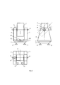
На рисунке (Фиг. 1) приведена принципиальная компоновочная схема автоматизированной противоградовой ПУ.The figure (Fig. 1) shows a basic layout diagram of an automated anti-hail launcher.
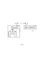
На рисунке (Фиг. 2) приведена блок-схема системы управления ПУ.The figure (Fig. 2) shows a block diagram of the PU control system.
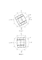
На рисунках (Фиг. 3 и Фиг. 4) приведены схемы исходного и конечного положения ПУ при наведении по азимуту и углу места, соответственно.The figures (Fig. 3 and Fig. 4) show the diagrams of the initial and final position of the launcher when aiming in azimuth and elevation, respectively.
ПУ (Фиг. 1) содержит неподвижное основание 1, размещенное на регулируемых по высоте опорных лапах 2. На неподвижном основании 1 размещен поворотный стол квадратной формы 3, на котором размещены опора с электромеханическим приводом наведения ПУ по азимуту 4, опора с приводом наведения ПУ по углу места 5 и блок управления цепями пуска ракет (привода наведения по азимуту и углу места и блок управления цепями пуска ракет на рисунке не показаны. Они схематично представлены на рисунке (Фиг. 2).PU (Fig. 1) contains a
На оси 6 между опорами 4 и 5 размещен с возможностью вращения в вертикальной плоскости блок направляющих 7 с каналами для размещения ракет. Для обеспечения удобства при проведении монтажных и пуско-наладочных работ, на конце оси 6, выступающей из опоры 4, размещено шкальное устройство со стрелочным указателем 8 и датчик угла места 9, а у основания поворотного стола 3, на оси неподвижного основания 1, размещено второе шкальное устройство со стрелочным указателем 10 и датчик азимута 11. На поворотном столе 3 размещен также контейнер с источником питания 12. Там же размещены элементы системы управления ПУ, которые на рисунке (Фиг. 1) не показаны. Они схематично представлены на рисунке (Фиг. 2).On the
Система управления ПУ (Фиг. 2) состоит из пульта дистанционного управления 13, состоящего из клавиатуры 14, первого контроллера 15 и первого радиомодема 16, снабженного всенаправленной антенной 17 для передачи команд управления на ПУ. На ПУ размещен второй радиомодем 18 с всенаправленной антенной 19, к выходу которого подключен второй контроллер 20, управляющие выходы которого, в свою очередь, подключены, соответственно, к электромеханическим приводам наведения ПУ по азимуту 21 и углу места 22, а также к блоку управления цепями пуска ракет 23.The CP control system (Fig. 2) consists of a
Автоматизированная ракетная пусковая установка работает следующим образом.An automated rocket launcher works as follows.
1. Команда на запуск ракеты формируется оператором в пультовой, расположенной в нескольких десятках метрах от ПУ. Оператор, получив по рации с командного пункта (на рисунках пункт не показан) необходимые данные по углам пуска ракет, вручную вводит с клавиатуры 14 ПДУ следующую информацию:1. The command to launch the rocket is formed by the operator in the control room, located a few tens of meters from the launcher. The operator, having received the necessary data on the angles of missile launch by the radio from the command post (the item is not shown in the figures), manually enters the following information from the
- азимут пуска, значение которого лежит в диапазоне 0°≤ψ1≤360°;- launch azimuth, the value of which lies in the range 0 ° ≤ψ 1 ≤360 °;
- угол места пуска, значение которого лежит в диапазоне 0°≤θ1≤85°;- angle of the launch site, the value of which lies in the range 0 ° ≤θ 1 ≤85 °;
- номер направляющей, из которой должен производиться пуск ракеты.- number of the guide from which the rocket should be launched.
2. Команда с клавиатуры 14 поступает в контроллер ПДУ 15, где кодируется, и посредством радиомодема 16, снабженного всенаправленной антенной 17, передается на ПУ.2. The command from the
3. На ПУ команда через вторую всенаправленную антенну 19 принимается радиомодемом 18, после чего поступает в контроллер 20.3. On the PU, the command through the second
4. Наряду с принятой командой, в контроллер ПУ 20 от датчиков 11 и 9 (датчики показаны на рисунке (Фиг. 1) поступает информация о текущем азимуте 0°≤ψ0≤360° и текущем угле места 0°≤θ0≤85°.4. Along with the received command, the
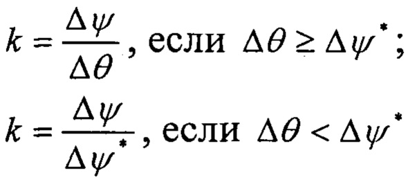
5. На основании этой информации, в контроллере 20, размещенном на ПУ, производится вычисление угла горизонтального наведения Δψ по формуле:5. Based on this information, in the
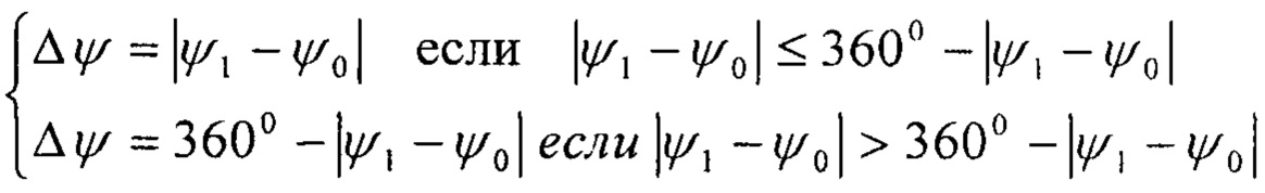
и угла вертикального наведения Δθ по формуле:and the angle of vertical guidance Δθ by the formula:
Δθ=180°-(θ0+θ1).Δθ = 180 ° - (θ 0 + θ 1 ).
6. Если Δψ≤90° или 90°<Δψ≤Δθ - наведение происходит по горизонтали и вертикали одновременно по кратчайшему расстоянию. Если Δψ>90° и Δψ>180°-(θ0+θ1) - наведение по горизонтали происходит в длинную сторону на угол Δψ*=180°-Δψ и параллельно происходит наведение по вертикали на угол Δθ=180°-(θ0+θ1), с перебрасыванием пакета направляющих через вертикаль. Выигрыш в скорости наведения при этом составит величину:6. If Δψ≤90 ° or 90 ° <Δψ≤Δθ - guidance occurs horizontally and vertically at the same time along the shortest distance. If Δψ> 90 ° and Δψ> 180 ° - (θ 0 + θ 1 ) - horizontal guidance occurs in the long side at an angle Δψ * = 180 ° -Δψ and in parallel there is vertical guidance at an angle Δθ = 180 ° - (θ 0 + θ 1 ), with the transfer of the package of guides over the vertical. The gain in guidance speed will be the following:
7. После того, как контроллер 20 рассчитал требуемые углы, он выдает команду на привод горизонтального наведения 21 и привод вертикального наведения 22.7. After the
8. После того, как получаемые от датчиков положения приводов значения текущего азимута и угла места совпадут с азимутом и углом места, переданных в команде, контроллер 20 выдает команду в блок управления цепями пуска ракет 23, откуда происходит подача импульса тока на разъем направляющей, номер которой был указан в команде. Данный импульс тока задействует воспламенитель топливного заряда ракеты, что приводит к ее старту.8. After the values of the current azimuth and elevation received from the actuator position sensors coincide with the azimuth and elevation transmitted in the command, the
Пример работы ПУ при заданных текущих и требуемых углах наведения.An example of the launcher operation at the specified current and required guidance angles.
Дано: Текущий азимут ψ0=60°. Текущий угол возвышения θ0=65°.Given: Current azimuth ψ 0 = 60 °. The current elevation angle is θ 0 = 65 °.
Требуемый азимут ψ1=270°. Требуемый угол возвышения θ1=65° (Фигура 3).The required azimuth is ψ 1 = 270 °. The required elevation angle θ 1 = 65 ° (Figure 3).
Определяем угол горизонтального наведения по формуле:Determine the angle of horizontal guidance by the formula:

Определяем угол вертикального наведения по формуле:Determine the angle of vertical guidance by the formula:
Δθ=180°-(θ0+θ1)⇒Δθ=50°.Δθ = 180 ° - (θ 0 + θ 1 ) ⇒Δθ = 50 °.
Так как Δψ>90° и Δψ>Δθ, применяем способ наведения с перебрасыванием пакета направляющих. Для его реализации установка разворачивается на угол Δψ*=180°-Δψ=30° по часовой стрелке (Фигура 3) и одновременно с этим пакет направляющих поворачивается в вертикальной плоскости на угол Δθ=180°-(θ0+θ1)=50° с переходом через вертикаль (Фигура 4).Since Δψ> 90 ° and Δψ> Δθ, we use the guidance method by throwing the package of guides. To implement it, the installation is rotated through the angle Δψ * = 180 ° -Δψ = 30 ° clockwise (Figure 3) and at the same time the package of guides is rotated in the vertical plane by the angle Δθ = 180 ° - (θ 0 + θ 1 ) = 50 ° with a transition through the vertical (Figure 4).
Выигрыш по времени перенаведения, по сравнению с применением обычной схемы (без перебрасывания пакета направляющих через вертикаль), составит:The gain in re-aiming time, in comparison with the use of the usual scheme (without throwing the package of guides over the vertical), will be:
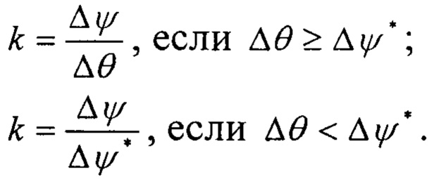
В нашем случае ![]()
![]()
Предлагаемая конструкция автоматизированной ПУ в сравнении с прототипом позволяет существенно повысить эффективность активных воздействий на градовые облака за счет увеличение скорострельности ПУ, а также исключения образования мертвой зоны в пространстве над ПУ.The proposed design of an automated launcher, in comparison with the prototype, can significantly increase the effectiveness of active influences on hail clouds by increasing the rate of fire of the launcher, as well as eliminating the formation of a dead zone in the space above the launcher.
Источники информацииInformation sources
1. Абшаев М.Т., Клигер Б.А. Методические указания по применению противоградового комплекса «Алазань» для активных воздействий на гидрометеорологические процессы. - Л.: Гидрометеоиздат, 1989. - 57 с.1. Abshaev M.T., Kliger B.A. Methodical instructions on the use of the anti-hail complex "Alazan" for active influences on hydrometeorological processes. - L .: Gidrometeoizdat, 1989 .-- 57 p.
2. Патент РФ №2276914 от 26.08.2003 // Абшаев М.Т., Кузнецов Б.К., Каиров A.M., Черкашин В.М., Гущин В.Д., Горбушин А.Л.2. RF patent №2276914 from 26.08.2003 // Abshaev MT, Kuznetsov B.K., Kairov A.M., Cherkashin V.M., Gushchin V.D., Gorbushin A.L.
3. Патент РФ №2370943 от 27.10.2009 // Абшаев A.M., Абшаев М.Т., Кузнецов Б.К. ПРОТОТИП.3. RF patent No. 2370943 dated 27.10.2009 // A.M. Abshaev, M.T. Abshaev, B.K. Kuznetsov. PROTOTYPE.
Claims (2)
Priority Applications (1)
| Application Number | Priority Date | Filing Date | Title |
|---|---|---|---|
| RU2020111244A RU2738319C1 (en) | 2020-03-17 | 2020-03-17 | Automated anti-hail rocket launcher |
Applications Claiming Priority (1)
| Application Number | Priority Date | Filing Date | Title |
|---|---|---|---|
| RU2020111244A RU2738319C1 (en) | 2020-03-17 | 2020-03-17 | Automated anti-hail rocket launcher |
Publications (1)
| Publication Number | Publication Date |
|---|---|
| RU2738319C1 true RU2738319C1 (en) | 2020-12-11 |
Family
ID=73834820
Family Applications (1)
| Application Number | Title | Priority Date | Filing Date |
|---|---|---|---|
| RU2020111244A RU2738319C1 (en) | 2020-03-17 | 2020-03-17 | Automated anti-hail rocket launcher |
Country Status (1)
| Country | Link |
|---|---|
| RU (1) | RU2738319C1 (en) |
Cited By (2)
| Publication number | Priority date | Publication date | Assignee | Title |
|---|---|---|---|---|
| RU2761886C1 (en) * | 2021-07-30 | 2021-12-13 | Публичное акционерное общество "Долгопрудненское научно-производственное предприятие" | Shipboard unit for a simulation rocket |
| RU2766029C1 (en) * | 2021-05-04 | 2022-02-07 | Акционерное общество "Чебоксарское производственное объединение имени В.И. Чапаева" | Rocket launcher |
Citations (4)
| Publication number | Priority date | Publication date | Assignee | Title |
|---|---|---|---|---|
| US2958261A (en) * | 1953-05-12 | 1960-11-01 | Henig Seymour | Predetermined target dispersal rocket launcher |
| RU2172458C2 (en) * | 1998-05-08 | 2001-08-20 | Войсковая часть 61469 | Automatic scanning launcher |
| RU2267914C2 (en) * | 2003-08-26 | 2006-01-20 | ОАО "Телемеханика" | Complex for acting upon clouds |
| RU2370943C1 (en) * | 2008-03-13 | 2009-10-27 | ООО Научно-Производственный Центр "Антиград-А" (ООО НПЦ "Антиград-А") | Automatic hail suppression rocket launcher |
-
2020
- 2020-03-17 RU RU2020111244A patent/RU2738319C1/en active
Patent Citations (4)
| Publication number | Priority date | Publication date | Assignee | Title |
|---|---|---|---|---|
| US2958261A (en) * | 1953-05-12 | 1960-11-01 | Henig Seymour | Predetermined target dispersal rocket launcher |
| RU2172458C2 (en) * | 1998-05-08 | 2001-08-20 | Войсковая часть 61469 | Automatic scanning launcher |
| RU2267914C2 (en) * | 2003-08-26 | 2006-01-20 | ОАО "Телемеханика" | Complex for acting upon clouds |
| RU2370943C1 (en) * | 2008-03-13 | 2009-10-27 | ООО Научно-Производственный Центр "Антиград-А" (ООО НПЦ "Антиград-А") | Automatic hail suppression rocket launcher |
Cited By (2)
| Publication number | Priority date | Publication date | Assignee | Title |
|---|---|---|---|---|
| RU2766029C1 (en) * | 2021-05-04 | 2022-02-07 | Акционерное общество "Чебоксарское производственное объединение имени В.И. Чапаева" | Rocket launcher |
| RU2761886C1 (en) * | 2021-07-30 | 2021-12-13 | Публичное акционерное общество "Долгопрудненское научно-производственное предприятие" | Shipboard unit for a simulation rocket |
Similar Documents
| Publication | Publication Date | Title |
|---|---|---|
| RU2738319C1 (en) | Automated anti-hail rocket launcher | |
| TW412639B (en) | Impulse radar guidance apparatus and method for use with guided projectiles | |
| CN107514936A (en) | A kind of short-range laser system of defense | |
| WO2007121393A2 (en) | Eliminating keyhole problems in an x-y gimbal assembly | |
| RU2370943C1 (en) | Automatic hail suppression rocket launcher | |
| CN103675802B (en) | The system and method for high powered radar proximity detection is realized with two-way feeder line | |
| CN109758693A (en) | A kind of electromagnetic launch device for high-rise conveying | |
| CN201725221U (en) | Intelligent infantry weapon robot device | |
| SG11201906993RA (en) | Antenna device, antenna control device, and method for controlling antenna device | |
| CN105437260A (en) | Robot chassis | |
| KR102605255B1 (en) | Grenade launch repulsion control device for drones | |
| CN101858710A (en) | Intelligent infantry weapon robot device | |
| GB1140602A (en) | Improvements in launching posts and in the remote control of missiles | |
| RU2564688C1 (en) | Missile-artillery mount | |
| RU2230278C1 (en) | Helicopter weapon guidance system | |
| RU2667102C2 (en) | Method and device for protection of a mobile facility of ground military equipment against high precision weapons | |
| CN110949690A (en) | Spacecraft structure for low-orbit geomagnetic energy storage in-orbit delivery | |
| RU2685948C1 (en) | Method of microsatellite spatial orientation | |
| RU2229670C1 (en) | System of object armament guidance on target | |
| SU1748736A1 (en) | Anti-hail missile complex | |
| CN104953232B (en) | A kind of antenna connection device and antenna system | |
| CN203534348U (en) | Automatic control device of '37' antiaircraft gun sighting device | |
| CN210242585U (en) | Cutting cable type active safety control device of missile-borne aircraft | |
| RU128308U1 (en) | BATTLE OF UNDERGROUND DELIVERY "MOLE" | |
| CN102963700B (en) | Mechanical device |