RU2737170C2 - Prefabricated module for pitched roof element and pitched roof element for building roof - Google Patents
Prefabricated module for pitched roof element and pitched roof element for building roof Download PDFInfo
- Publication number
- RU2737170C2 RU2737170C2 RU2018133868A RU2018133868A RU2737170C2 RU 2737170 C2 RU2737170 C2 RU 2737170C2 RU 2018133868 A RU2018133868 A RU 2018133868A RU 2018133868 A RU2018133868 A RU 2018133868A RU 2737170 C2 RU2737170 C2 RU 2737170C2
- Authority
- RU
- Russia
- Prior art keywords
- beams
- layer
- insulation
- roof
- modules
- Prior art date
Links
Images


Classifications
-
- E—FIXED CONSTRUCTIONS
- E04—BUILDING
- E04B—GENERAL BUILDING CONSTRUCTIONS; WALLS, e.g. PARTITIONS; ROOFS; FLOORS; CEILINGS; INSULATION OR OTHER PROTECTION OF BUILDINGS
- E04B7/00—Roofs; Roof construction with regard to insulation
- E04B7/20—Roofs consisting of self-supporting slabs, e.g. able to be loaded
- E04B7/22—Roofs consisting of self-supporting slabs, e.g. able to be loaded the slabs having insulating properties, e.g. laminated with layers of insulating material
- E04B7/225—Roofs consisting of self-supporting slabs, e.g. able to be loaded the slabs having insulating properties, e.g. laminated with layers of insulating material the slabs having non-structural supports for roofing materials
-
- E—FIXED CONSTRUCTIONS
- E04—BUILDING
- E04B—GENERAL BUILDING CONSTRUCTIONS; WALLS, e.g. PARTITIONS; ROOFS; FLOORS; CEILINGS; INSULATION OR OTHER PROTECTION OF BUILDINGS
- E04B1/00—Constructions in general; Structures which are not restricted either to walls, e.g. partitions, or floors or ceilings or roofs
- E04B1/18—Structures comprising elongated load-supporting parts, e.g. columns, girders, skeletons
- E04B1/26—Structures comprising elongated load-supporting parts, e.g. columns, girders, skeletons the supporting parts consisting of wood
-
- E—FIXED CONSTRUCTIONS
- E04—BUILDING
- E04B—GENERAL BUILDING CONSTRUCTIONS; WALLS, e.g. PARTITIONS; ROOFS; FLOORS; CEILINGS; INSULATION OR OTHER PROTECTION OF BUILDINGS
- E04B7/00—Roofs; Roof construction with regard to insulation
- E04B7/02—Roofs; Roof construction with regard to insulation with plane sloping surfaces, e.g. saddle roofs
- E04B7/04—Roofs; Roof construction with regard to insulation with plane sloping surfaces, e.g. saddle roofs supported by horizontal beams or the equivalent resting on the walls
-
- E—FIXED CONSTRUCTIONS
- E04—BUILDING
- E04B—GENERAL BUILDING CONSTRUCTIONS; WALLS, e.g. PARTITIONS; ROOFS; FLOORS; CEILINGS; INSULATION OR OTHER PROTECTION OF BUILDINGS
- E04B7/00—Roofs; Roof construction with regard to insulation
- E04B7/20—Roofs consisting of self-supporting slabs, e.g. able to be loaded
- E04B7/22—Roofs consisting of self-supporting slabs, e.g. able to be loaded the slabs having insulating properties, e.g. laminated with layers of insulating material
-
- E—FIXED CONSTRUCTIONS
- E04—BUILDING
- E04B—GENERAL BUILDING CONSTRUCTIONS; WALLS, e.g. PARTITIONS; ROOFS; FLOORS; CEILINGS; INSULATION OR OTHER PROTECTION OF BUILDINGS
- E04B7/00—Roofs; Roof construction with regard to insulation
- E04B7/20—Roofs consisting of self-supporting slabs, e.g. able to be loaded
- E04B7/24—Roofs consisting of self-supporting slabs, e.g. able to be loaded the slabs being collapsible or retractable, e.g. for transport
-
- E—FIXED CONSTRUCTIONS
- E04—BUILDING
- E04D—ROOF COVERINGS; SKY-LIGHTS; GUTTERS; ROOF-WORKING TOOLS
- E04D13/00—Special arrangements or devices in connection with roof coverings; Protection against birds; Roof drainage; Sky-lights
- E04D13/16—Insulating devices or arrangements in so far as the roof covering is concerned, e.g. characterised by the material or composition of the roof insulating material or its integration in the roof structure
- E04D13/1606—Insulation of the roof covering characterised by its integration in the roof structure
- E04D13/1612—Insulation of the roof covering characterised by its integration in the roof structure the roof structure comprising a supporting framework of roof purlins or rafters
- E04D13/1625—Insulation of the roof covering characterised by its integration in the roof structure the roof structure comprising a supporting framework of roof purlins or rafters with means for supporting the insulating material between the purlins or rafters
- E04D13/1631—Insulation of the roof covering characterised by its integration in the roof structure the roof structure comprising a supporting framework of roof purlins or rafters with means for supporting the insulating material between the purlins or rafters the means deriving from the nature or the shape of the insulating material itself
Abstract
Description
Настоящее изобретение относится к предварительно изготовленному модулю для элемента скатной крыши, содержащему каркас, выполненный из по меньшей мере двух первых балок, расположенных на расстоянии и проходящих параллельно друг другу, и двух вторых балок, проходящих перпендикулярно первым балкам и присоединенных к концам первых балок с образованием сквозной конструкции, в которую помещен первый слой изоляции. Дополнительно, настоящее изобретение относится к элементу скатной крыши здания для крыши здания, выполненному из по меньшей мере двух модулей, каждый из которых имеет каркас, выполненный из по меньшей мере первых балок, расположенных на расстоянии и проходящих параллельно друг другу, и двух вторых балок, проходящих перпендикулярно первым балкам и присоединенных к концам первых балок с образованием сквозной конструкции, в которую помещен первый слой изоляции. The present invention relates to a prefabricated module for a pitched roof element comprising a frame made up of at least two first beams spaced apart and running parallel to each other and two second beams extending perpendicular to the first beams and connected to the ends of the first beams to form a through structure in which the first layer of insulation is placed. Additionally, the present invention relates to a pitched building roof element for a building roof, made of at least two modules, each of which has a frame made of at least first beams spaced apart and running parallel to each other, and two second beams, extending perpendicularly to the first beams and attached to the ends of the first beams to form a through structure in which the first insulation layer is placed.
В целом, известно о предоставлении изоляционного узла крепления крыши для конструкции крыши, содержащего множество удлиненных стропил, расположенных на заданном расстоянии от брусьев для изоляции между ними. На верхней части такого узла крепления крыши закреплена черепица или другие типы кровельного покрытия. In general, it is known to provide an insulating roof attachment assembly for a roof structure comprising a plurality of elongated rafters spaced a predetermined distance from the joists to insulate therebetween. Tiles or other types of roofing are attached to the top of such a roof attachment.
Также известно о предоставлении решений в отношении новых зданий, а также зданий, находящихся на реконструкции, чтобы справиться с постоянно увеличивающимися требованиями, обозначенными применительно к теплоизоляции в отношении энергосбережения. It is also known to provide solutions for new buildings as well as buildings undergoing renovation to cope with the ever-increasing demands placed on thermal insulation for energy savings.
Тем не менее пристройка крыши, в частности скатной крыши, к сборной конструкции всегда занимает много времени, так как кровельщикам необходимо выполнить много производственных этапов, пока крыша не будет закончена. Все этапы должны быть выполнены на месте строительства плотниками и кровельщиками. В случае со скатной крышей это приходится делать на наклонном строительном каркасе. However, it is always time consuming to add a roof, in particular a pitched roof, to a prefabricated structure, as roofers have to complete many manufacturing steps until the roof is finished. All steps must be carried out on site by carpenters and roofers. In the case of a pitched roof, this has to be done on an inclined building frame.
Прежде всего, конструкции крыши, как правило из дерева, необходимо установить на верхней части верхнего этажа сборной конструкции здания. Как правило, такие конструкции крыши из дерева состоят из кровельных балок, стропил, ригелей и т. д. После завершения конструкций крыши из древесных обрешеток, в основном обрешетки для шиферной кровли и для черепичной кровли должны быть прикреплены к верхней части стропил до закрепления, например, черепицы на обрешетках для заключительной защиты конструкции крыши здания от непогоды. Изоляционный материал должен быть помещен между стропилами и/или обрешетками для удовлетворения требованиям относительно теплоизоляции. Поскольку все эти действия необходимо выполнять на месте строительства, все действия зависят от погодных условий. В случае неблагоприятных погодных условий эти действия могут быть приостановлены, а сроки окончания всего проекта могут быть перенесены. First of all, roof structures, usually made of wood, need to be installed on the top of the top floor of a prefabricated building. Typically, these timber roof structures are composed of roof beams, rafters, crossbars, etc. After the completion of timber batten roof structures, generally slate roof battens and tiled roof battens should be attached to the top of the rafters before being secured, for example , roof tiles on battens for the final protection of the building roof structure from bad weather. Insulation material must be placed between rafters and / or battens to meet thermal insulation requirements. Since all these actions must be performed at the construction site, all actions depend on weather conditions. In the event of adverse weather conditions, these actions may be suspended, and the completion date of the entire project may be postponed.
В заявке WO 2009/153232 раскрывается изоляционная строительная система для внешней конструкции здания, такой как стена или крыша, или внутренней конструкции здания вышеупомянутого типа. Эта сборная конструкция здания имеет верхний и нижний профиль с множеством соединительных профилей между верхним и нижним каркасными профилями. Соединительные профили имеют первую и вторую боковые поверхности, которые соприкасаются контактными сторонами смежных изоляционных панелей с каждой стороны указанных соединительных профилей, при этом контактные стороны профиля изоляционных панелей имеют форму, соответствующую боковым поверхностям соединительных профилей таким образом, что изоляционные панели фиксируются между двумя профилями. Таким образом, изоляционные панели поддерживают соединительные профили и обеспечивают стабильность и устойчивость к конструкции стены, а также предохраняют соединительные профили от изгибания. WO 2009/153232 discloses an insulating building system for an external building structure such as a wall or a roof, or an internal building structure of the aforementioned type. This prefabricated building structure has an upper and lower profile with a plurality of connecting profiles between the upper and lower frame profiles. The connecting profiles have first and second lateral surfaces which are in contact with the contact sides of adjacent insulating panels on each side of said connecting profiles, while the contact sides of the insulating panel profile are shaped to match the lateral surfaces of the connecting profiles so that the insulating panels are fixed between the two profiles. Thus, the insulating panels support the connecting profiles and provide stability and resistance to the wall structure, and also prevent the connecting profiles from bending.
Однако эти известные изоляционные строительные системы зачастую являются составными, их сложно установить на крыше, и, кроме того, существует растущий спрос на дополнительную теплоизоляцию в конструкциях крыш для обеспечения комплексной теплоизоляции здания. However, these known insulation building systems are often composite, difficult to install on the roof, and there is also an increasing demand for additional thermal insulation in roof structures to provide comprehensive thermal insulation for a building.
Таким образом, целью настоящего изобретения является предоставление предварительно изготовленного модуля для элемента скатной крыши, который можно легко установить на сборной конструкции здания, при этом установка может быть выполнена в кратчайшие сроки с высокой степенью безопасности для монтажника, и при этом элемент крыши имеет, в конечном итоге, теплоизоляционные характеристики, удовлетворяющие растущие потребности для обеспечения комплексной теплоизоляции здания. Thus, it is an object of the present invention to provide a prefabricated module for a pitched roof element that can be easily installed on a prefabricated building structure, the installation can be carried out in the shortest possible time with a high degree of safety for the installer, and the roof element ultimately has As a result, thermal insulation characteristics that meet the growing needs to provide comprehensive thermal insulation of the building.
Эта цель достигается с помощью предварительно изготовленного модуля, содержащего каркас, выполненный из по меньшей мере двух первых балок, как правило деревянных стропил, расположенных на расстоянии и проходящих параллельно друг другу, и двух вторых балок, проходящих перпендикулярно первым балкам с образованием сквозной конструкции, в которую помещен первый слой изоляции, выполненный из минеральных волокон и связующего средства. Предварительно изготовленный модуль дополнительно содержит второй слой изоляции, расположенный над первым слоем изоляции, покрывающий каркас и прикрепленный к по меньшей мере первым и/или вторым балкам, при этом второй слой изоляции имеет более высокую объемную плотность, чем у первого слоя изоляции, и при этом первые балки имеют длину, по меньшей мере равную протяженности крыши между коньковым прогоном и мауэрлатом. Необходимо отметить, что в контексте настоящего изобретения изоляцию, выполненную из минеральных волокон и связующего средства, нужно понимать как изоляционную продукцию, изготовленную с помощью Европейского стандарта EN 13162 и в соответствии с ним.This objective is achieved with a prefabricated module comprising a frame made up of at least two first beams, typically wooden rafters, spaced apart and running parallel to each other, and two second beams running perpendicular to the first beams to form a through structure, in which contains the first layer of insulation made of mineral fibers and a binder. The prefabricated module further comprises a second insulation layer located above the first insulation layer, covering the frame and attached to at least the first and / or second beams, the second insulation layer having a higher bulk density than the first insulation layer, and at the same time the first beams have a length at least equal to the length of the roof between the ridge girder and the mauerlat. It should be noted that in the context of the present invention, insulation made of mineral fibers and a binder is to be understood as an insulation product made according to and in accordance with the European standard EN 13162.
Главным преимуществом такого предварительно изготовленного модуля является то, что лишь этот модуль должен быть использован для построения первой половины элемента скатной крыши, проходящего от конькового прогона к мауэрлату. Модуль уже имеет превосходные теплоизоляционные характеристики, так как он содержит два слоя изоляционного материала, в частности выполнен из минеральных волокон и связующего средства. Дополнительно, второй слой изоляции имеет высокую объемную плотность и улучшенное механическое сопротивление, таким образом рабочие могут ходить по изоляции и стоять на ней без риска повредить изоляцию и получить травму. Это обеспечивает высокий уровень безопасности рабочих во время установки.The main advantage of such a prefabricated module is that only this module must be used to construct the first half of the pitched roof element extending from the ridge girder to the Mauerlat. The module already has excellent thermal insulation characteristics, since it contains two layers of insulating material, in particular made of mineral fibers and a binder. Additionally, the second layer of insulation has a high bulk density and improved mechanical resistance, so workers can walk on and stand on the insulation without the risk of damaging the insulation and getting injured. This ensures a high level of worker safety during installation.
Дополнительно, цели достигают с помощью элемента скатной крыши, выполненного из двух модулей, каждый из которых содержит каркас, выполненный из по меньшей мере двух первых балок, расположенных на расстоянии и проходящих параллельно друг другу, и двух вторых балок, проходящих перпендикулярно первым балкам и присоединенных к концам первых балок с образованием сквозной конструкции, в которую помещен первый слой изоляции, выполненный из минеральных волокон и связующего средства, при этом модули соединены друг с другом с возможностью поворота с помощью шарнира, присоединенного ко второй балке каждого каркаса так, чтобы каркасы могли быть перемещены из положения, в котором первые балки каркасов проходят параллельно друг другу и опираются друг на друга, в положение, в котором каркасы заключают угол между первыми балками в области шарнира, который соответствует по меньшей мере углу между двумя половинами крыши, находящимися в V-образном выравнивании. Additionally, the objectives are achieved with a pitched roof element made of two modules, each of which comprises a frame made of at least two first beams spaced apart and running parallel to each other, and two second beams running perpendicular to the first beams and connected to the ends of the first beams with the formation of a through structure, in which the first layer of insulation made of mineral fibers and a binder is placed, while the modules are pivotally connected to each other by means of a hinge connected to the second beam of each frame so that the frames can be moved from the position in which the first frame beams run parallel to each other and rest on each other to the position in which the frames enclose an angle between the first frame beams in the hinge region, which corresponds to at least the angle between the two roof halves located in the V-shaped alignment.
Такой элемент скатной крыши, выполненный из двух модулей, имеет большое преимущество в том, что, теоретически, вся крыша может быть изготовлена заранее. В зависимости от ширины здания, которое нужно покрыть указанными элементами крыши, один или более элементов можно располагать рядом с другими, но всю крышу изготавливают заранее за пределами места стройки. Такие элементы легко транспортировать, так как две половины элементов крыши присоединяют друг к другу с помощью шарнира с возможностью поворота. При транспортировке вся крыша может быть завернута в пленку для защиты от неблагоприятных погодных условий. На месте строительства элементы крыши можно поднять с помощью крана к верхней части сборной конструкции здания после того, как два модуля элемента скатной крыши переместят в положение V-образного выравнивания. Элемент скатной крыши может быть расположен в верхней части сборной конструкции здания, прикреплен к ней, после чего можно приступать к финальным этапам по завершению крыши, например, размещению покрытия в верхней части модулей. Такой элемент скатной крыши легко и быстро устанавливается, что значительно снижает время построения, например, жилых домов. Дополнительным аспектом является предварительное изготовление скатных крыш при условии, что они состоят из двух предварительно изготовленных модулей, которые могут быть изготовлены заранее на фабрике со всеми необходимыми деталями и при определенных условиях. Such a pitched roof element made of two modules has the great advantage that, in theory, the entire roof can be prefabricated. Depending on the width of the building to be covered with these roof elements, one or more elements can be placed next to others, but the entire roof is made in advance outside the construction site. Such elements are easy to transport since the two halves of the roof elements are pivotally connected to each other by means of a hinge. During transportation, the entire roof can be wrapped in foil to protect it from adverse weather conditions. On site, the roof elements can be lifted with a crane to the top of the prefabricated building after the two pitched roof element modules are moved to the V-alignment position. The pitched roof element can be positioned at the top of the prefabricated building structure, attached to it, after which the final steps can be taken to complete the roof, such as placing the cover on the top of the modules. Such a pitched roof element is easy and quick to install, which significantly reduces the construction time, for example, of residential buildings. An additional aspect is the pre-fabrication of pitched roofs, provided that they consist of two pre-fabricated modules, which can be pre-fabricated in the factory with all the necessary parts and under certain conditions.
Согласно дополнительному варианту осуществления предварительно изготовленного модуля первые балки и/или вторые балки соединены с плитой, например, облицовочной плитой, расположенной смежно с первым слоем изоляции, и/или изолирующее покрытие расположено смежно со вторым слоем изоляции. Использование плит, расположенных смежно с первым слоем изоляции, соединенным с первыми балками и/или вторыми балками, обеспечивает модуль с более высокой стабильностью и упрощает установку первого слоя изоляции в сквозную конструкцию, так как эта сквозная конструкция уже закрыта с одной стороны. Первый слой изоляции как правило представляет собой сетчатый изоляционный материал, выполненный из минеральных волокон и связующего средства. Такой слой изоляции как правило оптимизируют применительно к его тепловым характеристикам, т.е. с относительно низкой объемной плотностью, например, от 20 до 40 кг/м3 и заявленной теплопроводностью приблизительно λD = от 0,030 до 0,035 Вт/(м·K). Изоляционный материал находится в зажимном контакте в сквозной конструкции, что обеспечивает преимущество в том, что слой изоляции находится в контакте со всеми балками, образующими сквозную конструкцию. Тепловые мосты не используют из-за щелей. According to a further embodiment of the prefabricated module, the first beams and / or second beams are connected to a slab, for example a cladding board, disposed adjacent to the first insulation layer and / or an insulating cover is disposed adjacent to the second insulation layer. The use of slabs adjacent to the first insulation layer connected to the first beams and / or second beams provides a module with higher stability and simplifies the installation of the first insulation layer in the through structure, since this through structure is already closed on one side. The first layer of insulation is usually a mesh insulation material made of mineral fibers and a binder. Such an insulation layer is usually optimized for its thermal characteristics, i.e. with a relatively low bulk density, for example, from 20 to 40 kg / m 3 and a declared thermal conductivity of approximately λ D = from 0.030 to 0.035 W / (m · K). The insulating material is in clamping contact in the through structure, which provides the advantage that the insulation layer is in contact with all beams forming the through structure. Thermal bridges are not used due to cracks.
Более того, паропроницаемое изолирующее покрытие расположено смежно со вторым слоем изоляции. Изолирующее покрытие закрывает верхнюю сторону второго слоя и может прикрепляться к внешним сторонам балок. Могут использоваться средства прикрепления, такие как, например, гвозди, зажимы, скобы и т.д. Изолирующее покрытие защищает слои изоляции от попадания воды и накопления влаги в конструкции. В какой-то мере оно также может защищать изоляцию от повреждений, нанесенных рабочими, которые ходят по ней во время закрепления покрытия крыши на верхней части модулей. Moreover, the vapor-permeable insulating cover is disposed adjacent to the second insulation layer. The insulating cover covers the top side of the second layer and can be attached to the outside of the beams. Attachment means such as nails, clamps, staples, etc. can be used. The insulating cover protects the insulation layers from water ingress and moisture accumulation in the structure. To some extent, it can also protect the insulation from damage caused by workers who walk on it while attaching the roof covering to the top of the modules.
В еще одном варианте осуществления настоящего изобретения второй слой изоляции представляет собой плиту с двойной плотностью, выполненную из минеральных волокон и связующего средства. Таким образом, второй слой изоляции содержит два слоя изоляционного материала, имеющего разные плотности. Верхний слой с большей объемной плотностью расположен на внешней стороне модуля, что обеспечивает усиленную защиту от повреждений, как было описано ранее. Дополнительно, такая плита с двойной плотностью имеет усовершенствованные тепловые характеристики, так как нижний слой с более низкой объемной плотностью имеет меньший коэффициент теплоусвоения, таким образом, улучшенные тепловые свойства, по сравнению с верхним слоем второго слоя изоляции, имеют большую объемную плотность. In yet another embodiment of the present invention, the second layer of insulation is a dual density board made of mineral fibers and a binder. Thus, the second layer of insulation contains two layers of insulating material having different densities. The top layer with a higher bulk density is located on the outside of the module, which provides enhanced protection against damage, as described earlier. Additionally, such a dual density board has improved thermal performance, since the lower bulk density layer has a lower heat absorption coefficient, thus the improved thermal properties have higher bulk density than the upper layer of the second insulation layer.
Предпочтительно второй слой изоляции имеет объемную плотность по меньшей мере 80 кг/м3 и/или заявленную теплопроводность по меньшей мере λD = 0,038 Вт/(м·K), и/или высокое механическое сопротивление, отмеченное сопротивлением точечной нагрузке, по меньшей мере 120 кПа, соответственно 600 Н на 50 см2, при деформации в 5 мм, в соответствии с Европейским стандартом EN 12430. Такой второй слой изоляции обеспечивает превосходные теплоизоляционные свойства и, более того, имеет высокое сопротивление точечной нагрузке, таким образом он защищен от повреждений рабочими, которые стоят на изоляции или ходят по ней. По тем же причинам второй слой изоляции обеспечивает большую безопасность во время установки элементов скатной крыши на крышу здания и последующей отделки либо черепицей, либо другими покрытиями.Preferably, the second layer of insulation has a bulk density of at least 80 kg / m 3 and / or a declared thermal conductivity of at least λ D = 0.038 W / (m K), and / or a high mechanical resistance, indicated by resistance to point load, of at least 120 kPa, respectively 600 N per 50 cm 2 , with a deformation of 5 mm, in accordance with the European standard EN 12430. This second layer of insulation provides excellent thermal insulation properties and, moreover, has a high resistance to point load, thus it is protected from damage workers who stand on or walk on isolation. For the same reasons, a second layer of insulation provides greater safety during the installation of the pitched roof elements on the roof of the building and subsequent finishing with either tiles or other coatings.
Согласно другому предпочтительному варианту осуществления настоящего изобретения контробрешетки, проходящие параллельно первым балкам, прикреплены к первым балкам и/или вторым балкам, при этом второй слой изоляции расположен между контробрешетками и каркасом. Настоящее изобретение в этом отношении обеспечивает дополнительное значительное преимущество вследствие уникального механического сопротивления второго слоя, а именно вследствие того, что высокое сопротивление точечной нагрузке служит для твердой поверхности или подстила для контробрешеток. Это особенно выгодно с точки зрения точности, которую необходимо достичь при установке указанных обрешеток в плоскости. Намного проще ходить по плоской поверхности крыши и добиться точного результата для облицовочного покрытия.According to another preferred embodiment of the present invention, counter-gratings running parallel to the first beams are attached to the first beams and / or second beams, with a second layer of insulation located between the counter-gratings and the frame. The present invention provides an additional significant advantage in this regard due to the unique mechanical resistance of the second layer, namely, because the high resistance to point loading serves for a hard surface or underlayment for counter-gratings. This is particularly advantageous in terms of the accuracy that must be achieved when installing these battens in the plane. It is much easier to walk on a flat roof surface and achieve accurate cladding results.
Более того, использование второго слоя изоляции, соединяющего пространство между каркасом и контробрешетками, обеспечивает практически теплоизоляционную конструкцию без мостика, которая полностью отвечает настоящим требованиям относительно теплоизоляции зданий. В качестве примера упоминают государственные строительные нормы Нидерландов, определяющие минимальные требования в так называемых «Строительных нормах и правилах», например, таблица 5.1. Для конструкций крыш, являющихся объектом настоящего изобретения, определяют, например, минимальный коэффициент теплосопротивления (RC), составляющий 6,0 (м2·K)/Вт. В зависимости от толщины слоев изоляции и всей конструкции, можно обеспечить коэффициенты RC, составляющие 7,0 (м2·K)/Вт и выше, для предварительно изготовленных модулей в отношении элементов скатной крыши.Moreover, the use of a second layer of insulation, connecting the space between the frame and the counter-battens, provides a practically insulating structure without a bridge, which fully meets the current requirements for thermal insulation of buildings. As an example, the Dutch state building codes are mentioned, which define the minimum requirements in the so-called “Building codes”, for example, table 5.1. For the roof structures of the present invention, for example, a minimum thermal resistance coefficient (R C ) of 6.0 (m 2 · K) / W is determined. Depending on the thickness of the insulation layers and the overall structure, R C ratios of 7.0 (m 2 · K) / W and higher can be achieved for prefabricated modules in relation to pitched roof elements.
Таким образом, элементы согласно настоящему изобретению также могут соответствовать, например, требованиям пассивного дома, в соответствии с рекомендациями Института пассивного дома (ИПД) Германии в городе Драмштадт, так как может быть предусмотрена конструкция крыши с коэффициентом теплоусвоения ≤ 0,12 Вт/(м2·K), в частности, с минимальным коэффициентом, составляющим 0,1 Вт/(м2·K).Thus, the elements according to the present invention can also meet, for example, the requirements of a passive house, in accordance with the recommendations of the German Passive House Institute (IPH) in Dramstadt, since a roof structure with a heat absorption coefficient ≤ 0.12 W / (m 2 K), in particular with a minimum coefficient of 0.1 W / (m 2 K).
Модули полностью изготовят заранее, поэтому необходимо только установить покрытие крыши после того, как модуль или элемент скатной крыши будет прикреплен к сборной конструкции здания. Для этого преимущественно использование обрешеток для черепичной кровли, проходящих параллельно вторым балкам, при этом коньковый прогон и мауэрлат прикрепляются к контробрешеткам. The modules will be completely prefabricated, so only the roof covering needs to be installed after the module or pitched roof element is attached to the prefabricated building structure. For this, it is preferable to use battens for tiled roofs running parallel to the second beams, while the ridge girder and Mauerlat are attached to the counter battens.
Дополнительный преимущественный модуль согласно настоящему изобретению характеризуется тем, что по меньшей мере дополнительная балка расположена между внешними первыми балками каркаса, при этом по меньшей мере две сквозные конструкции расположены между двумя балками, и при этом сквозные конструкции имеют идентичные размеры длины, и/или ширины, и/или высоты. Такие модули могут быть созданы с одной, двумя, тремя или более сквозными конструкциями. Каждая сквозная конструкция имеет ширину согласно обычно используемым полотнам, выполненным из минеральных волокон и связующего средства, находящихся в зажимном контакте в сквозных конструкциях. Согласно этому, так как сквозные конструкции создают в соответствии с обычно используемыми полотнами с определенной шириной, модули разной ширины могут изготавливать и использовать для построения скатных крыш разной длины. Такие модули можно использовать в качестве строительного комплекта, предоставляющего возможность получения суммарной максимальной длины крыши в направлении прогонов, что используется в основном в жилых домах. Модули, создающие одну часть элемента скатной крыши, могут располагать разными способами и соединять с помощью винтов, проходящих через первые балки. Во избежание появления тепловых мостов тонкие слои изоляционного материала, выполненного, в частности, из минеральных волокон и связующего средства, могут располагать между двумя первыми балками соседних модулей. An additional advantageous module according to the present invention is characterized in that at least an additional beam is located between the outer first beams of the frame, while at least two through structures are located between two beams, and the through structures have identical length and / or width dimensions, and / or heights. Such modules can be created with one, two, three or more pass-through structures. Each through structure has a width according to commonly used webs made of mineral fibers and a binder in clamping contact in the through structures. Accordingly, since through structures are created in accordance with commonly used canvases with a certain width, modules of different widths can be made and used to construct pitched roofs of different lengths. Such modules can be used as a building kit providing the ability to obtain the total maximum roof length in the direction of the purlins, which is mainly used in residential buildings. Modules that create one part of a pitched roof element can be positioned in different ways and connected using screws passing through the first beams. To avoid thermal bridges, thin layers of insulating material, in particular made of mineral fibers and a binder, can be placed between the two first beams of adjacent modules.
В конечном итоге, второй слой изоляции имеет толщину от 60 мм до 160 мм, являясь более тонким по сравнению с толщиной каркаса и/или первого слоя изоляции, имеющего толщину по меньшей мере 200 мм. Эти толщины могут дополнительно увеличиваться, чтобы соответствовать будущим требованиям к теплоизоляции и энергоэффективности.Ultimately, the second insulation layer has a thickness of 60 mm to 160 mm, being thinner than the thickness of the frame and / or the first insulation layer having a thickness of at least 200 mm. These thicknesses can be increased further to meet future insulation and energy efficiency requirements.
Элемент скатной крыши согласно настоящему изобретению преимущественно усовершенствован в том, что каждый модуль содержит второй слой изоляции, расположенный над первым слоем изоляции, покрывающий каркас и прикрепленный к по меньшей мере первым и/или вторым балкам, при этом второй слой изоляции имеет большую объемную плотность, чем у первого слоя изоляции, и при этом первые балки имеют длину, соответствующую по меньшей мере протяженности крыши между коньковым прогоном и мауэрлатом. Дополнительно, преимуществом является наличие контробрешеток, проходящих параллельно первым балкам и прикрепленных к первым балкам и/или вторым балкам, при этом второй слой расположен между контробрешетками и каркасом, и вторых обрешеток, проходящих параллельно вторым балкам, при этом коньковый прогон и мауэрлат прикреплен к контробрешеткам. Такая крыша в основном изготавливается заранее и готова к установке на верхнюю часть сборной конструкции здания, при этом только покрытие крыши должно быть размещено рабочими на верхней части контробрешеток. Преимуществом может являться внедрение дополнительных изоляционных элементов между этими контробрешетками для увеличения теплоизоляционных характеристик элемента скатной крыши. The pitched roof element according to the present invention is advantageously improved in that each module comprises a second insulation layer located above the first insulation layer, covering the frame and attached to at least the first and / or second beams, the second insulation layer having a higher bulk density, than the first layer of insulation, and the first beams have a length corresponding to at least the length of the roof between the ridge girder and the Mauerlat. Additionally, it is an advantage to have counter-battens running parallel to the first beams and attached to the first beams and / or second beams, with the second layer located between the counter-battens and the frame, and second battens running parallel to the second beams, with the ridge run and Mauerlat attached to the counter-battens ... Such a roof is generally prefabricated and ready to be installed on the top of the prefabricated building structure, with only the roof covering to be placed by workers on the top of the counter battens. An advantage may be the introduction of additional insulation elements between these counter-battens to increase the thermal insulation performance of the pitched roof element.
В конечном итоге, согласно дальнейшей разработке крыши оба модуля имеют по меньшей мере одну точку крепления, к которой можно прикреплять элемент для сохранения V-образного выравнивания модулей по меньшей мере до тех пор, пока модули не будут прикреплены к зданию. Этот элемент упрощает установку предварительно изготовленного элемента скатной крыши; и преимуществом является использование двух элементов по обеим сторонам двух модулей непосредственно для придания устойчивости двум половинам крыши в V-образном выравнивании до их помещения на сборной конструкции здания. Ultimately, according to the further development of the roof, both modules have at least one attachment point to which an element can be attached to maintain the V-alignment of the modules at least until the modules are attached to the building. This element facilitates the installation of a prefabricated pitched roof element; and it is advantageous to use two elements on either side of the two modules directly to stabilize the two roof halves in a V-alignment before placing them on the prefabricated building structure.
Ранее описанное изобретение относится в основном к элементу скатной крыши, имеющему высокие коэффициенты изоляции, открытую для испарений конструкцию и не имеющему тепловых мостов. Дополнительно, эта крыша согласно настоящему изобретению имеет характеристики воздухонепроницаемой системы с высокими акустическими характеристиками. Вся конструкция, включая несущие части, имеет исключительную огнестойкость, поэтому оборудование, например, солнечные панели или им подобное, может быть установлено над стропилами. Крыша согласно настоящему изобретению имеет высокую стойкость к механическим воздействиям и поэтому подходит для поддерживания такого оборудования, и, в частности, подходит для возможности ходить по ней даже по участкам слоев изоляции без риска повреждения изоляции. Дополнительно, плиты на основе минераловатного утеплителя могут быть использованы в качестве второго слоя изоляции на верхней части каркаса, который покрывает каркас и первый слой изоляции. Данный второй слой изоляции может быть прикреплен гвоздями к каркасу, что дополнительно снижает количество тепловых мостов и что можно легко сделать с помощью вбивания гвоздей через второй слой изоляционного материала в балки каркаса. The invention previously described relates generally to a pitched roof element having high insulation coefficients, a vapor-open structure and no thermal bridges. Additionally, this roof according to the present invention has the characteristics of an airtight system with high acoustic performance. The entire structure, including the load-bearing parts, is extremely fire resistant, so equipment such as solar panels or the like can be installed above the rafters. The roof according to the present invention is highly resistant to mechanical stress and is therefore suitable for supporting such equipment, and in particular is suitable for being able to walk on it even over portions of insulation layers without risk of damage to the insulation. Additionally, mineral wool slabs can be used as a second insulation layer on the top of the frame, which covers the frame and the first insulation layer. This second layer of insulation can be nailed to the frame, which further reduces thermal bridging and can easily be done by driving nails through the second layer of insulation into the frame beams.
Крыша согласно настоящему изобретению является преимущественной, так как изоляционные элементы имеют достаточную устойчивость и хорошую несущую способность, в частности, в случае новых зданий, в то же время они являются достаточно гибкими, таким образом можно избежать любой неровности в деревянных стропилах, используя предварительно изготовленные модули, имеющие уже включенные в них стропила. The roof according to the present invention is advantageous since the insulating elements have sufficient stability and good load-bearing capacity, in particular in the case of new buildings, while at the same time they are flexible enough so that any unevenness in the timber rafters can be avoided by using prefabricated modules. having rafters already included in them.
Далее настоящее изобретение описано более подробно со ссылкой на сопутствующие графические материалы, на которых: Hereinafter, the present invention is described in more detail with reference to the accompanying drawings, which:
на фиг. 1 показан перспективный вид части крыши здания с элементами скатной крыши, выполненными из предварительно изготовленных модулей; in fig. 1 shows a perspective view of a portion of the roof of a building with pitched roof elements made from prefabricated modules;
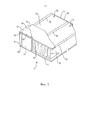
на фиг. 2 показан перспективный вид модуля в разрезе;in fig. 2 shows a perspective sectional view of the module;
на фиг. 3 показан вид сбоку в разрезе модуля по фиг. 2 с дополнительными контробрешетками; in fig. 3 is a cross-sectional side view of the module of FIG. 2 with additional counter grilles;
на фиг. 4 показан увеличенный вид сбоку в разрезе модуля по фиг. 3 иin fig. 4 is an enlarged cross-sectional side view of the module of FIG. 3 and
на фиг. 5 показан увеличенный вид в разрезе элемента скатной крыши по фиг. 1 при соединении двух модулей.in fig. 5 is an enlarged sectional view of the pitched roof element of FIG. 1 when connecting two modules.
На фиг. 1 показана часть крыши здания с тремя элементами 1 скатной крыши, расположенными на сборной конструкции 2 здания, такой как в жилых домах. Каждый элемент крыши состоит из двух модулей 3, которые описаны ниже и расположены с V-образным выравниванием; каждый модуль 3 составляет одну половину элемента 1 крыши. FIG. 1 shows a portion of the roof of a building with three pitched roof elements 1 located on a prefabricated building structure 2, such as in residential buildings. Each roof element consists of two
Модули 3 соединены с помощью шарнира 4, расположенного в области конькового прогона 5. Указанный шарнир 4 позволяет двум модулям 3 перемещаться из положения, в котором модули 3 лежат параллельно друг другу, в положение, показанное на фиг. 1, в котором модули 3 заключают угол между модулями 3 в области шарнира 4 и конькового прогона 5, который соответствует углу между двумя модулями 3 элемента 1 крыши, находящимися в V-образном выравнивании на сборной конструкции 2 здания. The
На фиг. 1 можно увидеть, что каждая половина крыши построена с использованием трех модулей 3, из которых два внешних модуля 3 имеют одинаковую ширину, а модуль 3, расположенный между внешними модулями 3, имеет меньшую ширину по сравнению с внешними модулями. Модуль 3, расположенный между внешними модулями 3, имеет ширину, которая приблизительно равна половине ширины внешних модулей 3. Модули 3 соединены с помощью винтов, которые не показаны и которые соединены с модулями 3, расположенными рядом друг с другом. FIG. 1, you can see that each half of the roof is built using three
Можно увидеть, что модули 3 проходят по меньшей мере от конькового прогона 5 до обоих мауэрлатов 6. It can be seen that
На фиг. 1 дополнительно показан элемент 7, который сохраняет модули 3 в V-образном выравнивании и который прикреплен к точкам 8 крепления и обоим модулям 3 элемента 1 крыши. Этот элемент 7 может быть прикреплен к точкам 8 крепления до поднятия элемента 1 крыши в V-образном выравнивании на сборную конструкцию 2 здания и может быть убран после того, как элемент 1 крыши будет прикреплен к сборной конструкции 2 здания.FIG. 1 additionally shows an
Очевидно, что преимуществом является использование двух таких элементов 7 по обеим сторонам элемента 1 крыши, в частности, если элемент 1 крыши полностью поднят на верхнюю часть сборной конструкции 2 здания. В отношении меньших модулей 3 одного элемента 7 может быть достаточно, и в частности, если крыша по фиг. 1 состоит из трех модулей 3 на каждой половине крыши, преимуществом является использование лишь одного элемента 7, так как этот элемент 7 должен быть убран до того, как следующую часть крыши, а именно два модуля 3, присоединенные с помощью шарнира 4, поднимут на верхнюю часть сборной конструкции 2 здания и присоединят к уже установленным модулям 3 элемента 1 крыши. Как правило, это свойственно для конструкции блокированных жилых домов. It is obviously advantageous to use two
На фиг. 2–4 более подробно показаны модули 3. На фиг. 2 показан модуль 3, содержащий каркас 9, выполненный из трех первых балок 10, расположенных на расстоянии и проходящих параллельно друг другу. Две вторые балки 11, проходящие перпендикулярно первым балкам 10, присоединены к концам первых балок 10 с помощью винтов или гвоздей. Дополнительно, в качестве соединительного средства может использоваться клей. Вторые балки 11 проходят параллельно друг другу на расстоянии друг от друга, соответствующем протяжению элемента 1 крыши от конькового прогона 5 до одного мауэрлата 6, и перекрывают элемент 1 крыши относительно сборной конструкции 2 здания. FIG. 2-4
Две соседние первые балки 10 и две вторые балки 11, расположенные на одной из сторон первых балок 10, обеспечивают сквозную конструкцию 12 прямоугольной формы, в которую помещается первый слой 13 изоляции, выполненный из минеральной шерсти, т.е. минеральных волокон и связующего средства. Первый слой 13 находится в зажимном контакте в сквозной конструкции 12, что означает, что первый слой 13 имеет ширину немного большую, чем расстояние между параллельно проходящими первыми балками 10. Two adjacent
Толщина первого слоя 13 изоляции соответствует высоте первых балок 10, однако также возможно использование сжимаемого первого слоя 13, который немного толще, чем высота первых балок 10; таким образом обеспечивается сквозная конструкция 12, при этом сквозная конструкция 12 полностью заполнена изоляционным материалом. The thickness of the
Первые балки 10 и вторые балки 11 соединены с плитой 14, закрывая сквозную конструкцию 12 со стороны каркаса 9. Балки 10, 11 и плита 14 выполнены из дерева. The first beams 10 and the
Соединение балок 10, 11 и плиты 14 можно обеспечить с помощью винтов и/или гвоздей и, дополнительно, за счет использования клейкого вещества. The connection of the
Согласно фиг. 2 предварительно изготовленный модуль 3 снабжен вторым слоем 15 изоляции, выполненным из плит, состоящих из минеральной шерсти, т. е. минеральных волокон и связующего средства. Плита представляет собой плиту с двойной плотностью, имеющую среднюю плотность приблизительно 90 кг/м3 и заявленную теплопроводность приблизительно λD = 0,038 Вт/(м·K). Так как эта плита представляет собой плиту с двойной плотностью, она имеет два слоя (не показаны) разных объемных плотностей, при этом слой с меньшей объемной плотностью направлен на первый слой 13 изоляции, который выходит к поверхностям 16 балок 10, 11. As shown in FIG. 2, the
На фиг. 2 можно увидеть, что плиты второго слоя 15 проходят от одной внешней первой балки 10 ко второй внешней первой балке 10, покрывая первую балку 10, расположенную в середине между двумя внешними первыми балками 10. Более того, можно увидеть, что продольное направление плиты, составляющей второй слой 15, перпендикулярно продольному направлению первого слоя 13, выполненного из полотна минеральных волокон. FIG. 2, it can be seen that the slabs of the
В конечном итоге на модуле 3 по фиг. 1 показано паропроницаемое изолирующее покрытие 17, покрывающее второй слой 15 и прикрепленное с помощью гвоздей 18, проходящих через второй слой 15 к балкам 10, 11. Зачастую крепление гвоздями паропроницаемого изолирующего покрытия 17 будет происходить с контробрешетками 19 и через них.Finally, in
Изолирующее покрытие 17 является водонепроницаемым и защищает модуль 3, в частности изоляционный материал, а также деревянные балки от попадания воды, которое может привести к повреждениям изоляции и/или механических деталей модуля 3. Можно увидеть, что часть изолирующего покрытия, покрывает внешнюю сторону первых балок 10, и, конечно, изолирующее покрытие 17 может быть расположено таким образом, чтобы внешние части вторых балок 11 также были покрыты изолирующим покрытием 17. The insulating
Один главный аспект модуля 3, показанного на фиг. 2, заключается в том, что из-за того, что второй слой 15 имеет большую объемную плотность, чем у первого слоя 13, модуль 3 является пригодным для хождения по модулю 3 даже в областях изоляции, не нанося повреждений изоляции. Это преимущество достигается за счет того, что используется второй слой 15, выполненный из плит и имеющий высокую объемную плотность, составляющую более 80 кг/м3, в частности более 120 кг/м3, определенную толщину и характеристики двойной плотности, таким образом это приводит к высокому механическому сопротивлению, определенному сопротивлением точечной нагрузке, составляющим по меньшей мере 120 кПа, соответственно 600 Н на 50 см2, при деформации в 5 мм, в соответствии с Европейским стандартом EN 12430. На фиг. 3 и 4 дополнительно показаны контробрешетки 19, проходящие параллельно первым балкам 11 и прикрепленные к первым балкам 10, а в области вторых балок 11 – ко вторым балкам 11, а также присоединенные, например, с помощью гвоздей (не показаны), проходящих через второй слой 15 в поверхности 16 балок 10, 11. Обрешетки 20 для черепичной кровли, расположенные поверх контробрешеток 19, проходят параллельно вторым балкам 11, коньковому прогону 5 и мауэрлату 6. Эти обрешетки 20 для черепичной кровли расположены на определенном расстоянии друг от друга, которое соответствует компонентам, использующимся для покрытия крыши. Этими компонентами может быть черепица, в частности плоская черепица. В отношении контробрешеток 19 следует отметить, что эти контробрешетки 19 расположены непосредственно над первыми балками 10. Обрешетки 20 для черепичной кровли могут быть прикреплены к контробрешеткам 19 с помощью гвоздей, проходящих через контробрешетки 19, второй слой 15 в первые балки 10. One major aspect of the
На фиг. 3 показан конкретный пример модуля 3 с четырьмя сквозными конструкциями 12, разделенными первыми балками 10, которые расположены на межцентровом расстоянии друг от друга, составляющем 610 мм. Каждая балка 10 имеет толщину 30 мм и высоту 220 мм, таким образом, первый слой 13 изоляции также имеет толщину 220 мм, чего также можно достичь после небольшого сжатия первого слоя 13. FIG. 3 shows a specific example of a
Второй слой 15 состоит из плит из минеральной шерсти, в частности выполненных из каменной ваты и связующего средства, с толщиной 60 мм, в результате чего общая высота модуля 3 без контробрешеток 19, 20 составляет 290 мм, что является дополнением к высоте второго слоя 15, первого слоя 13 и толщине облицовочной плиты 14, составляющей 10 мм. Второй слой 15, выполненный из плит двойной плотности, устраняет тепловые мосты и предоставляет возможность стоять на всей поверхности модуля 3. Модуль 3 согласно настоящему изобретению создает безопасную, открытую для испарений конструкцию, которая вполне может рассматриваться как предварительно изготовленный модуль или предварительно изготовленный элемент 1 крыши, что уменьшает время, необходимое для установки крыши сборной конструкции 2 здания. Минеральная шерсть обеспечивает весьма низкое значение сопротивления диффузии водяного пара, которое, предположительно, равняется µ=1. Таким образом, слой изоляции будет обеспечивать возможность беспрепятственного выхода влаги, попавшей в конструкцию, без нанесения вреда. Конструкция, описанная выше и показанная далее на фиг. 4, с высотой 290 мм, облицовочной плитой 14, составляющей 10 мм (древесностружечной плитой, µ=10) внизу и паропроницаемым изолирующим покрытием 17 (например, MorgoVent 120, µ=200) наверху, обеспечит общее µd-значение всей конструкции, равное µd=0,4298 м. Моделирование с использованием инструментов Glaser, основанное на EN ISO 13788, климатического класса 2 подтверждает, что в конструкции не возникнет ни конденсации, ни, таким образом, накапливания влаги. Поэтому вследствие паропроницаемости изоляции и изолирующего покрытия 17 деревянные балки защищены с помощью внутреннего климата. Процент внутренней влажности древесины находится под защитой и, таким образом, обеспечивается прочная конструкция крыши. Это уже является дополнительным существенным преимуществом конструкции скатной крыши, в которой используются модули и элементы согласно настоящему изобретению. The
Более того, второй слой 15 обеспечивает более значимое дополнительное преимущество в отношении акустики и, конечно, накапливания тепла и пожарной безопасности. Тепловые характеристики конструкции, в данном случае элемента 1 крыши и модулей 3, отображены с помощью теплового сопротивления или коэффициента теплосопротивления (RC) в соответствии, например, со стандартом NEN 1068 Нидерландов и будут составлять минимум 7,0 Вт/(м2·K). В зависимости от толщины второго слоя 15 тепловое сопротивление может варьироваться в пределах от 60 мм для RC = 7,0 Вт/(м2·K), 100 мм для RC = 8,0 Вт/(м2·K) до 140 мм для RC = 9,0 Вт/(м2·K) или даже выше. Moreover, the
На фиг. 5 показан увеличенный вид сбоку элемента 1 скатной крыши по фиг. 1 при соединении двух модулей 3 с помощью шарнира 4. Шарнир 4 состоит из двух деревянных петель 23, соединенных друг с другом с возможностью поворота, при этом каждая из них прикреплена к модулю 3 посредством винтов 24. Петли 23 проходят вдоль всего модуля 3. FIG. 5 is an enlarged side view of the pitched roof element 1 of FIG. 1 when two
Дополнительно, на фиг. 5 можно увидеть, что полоска 25 изоляционного материала помещается между двумя модулями, проходящими от конькового бруса к шарниру 4. Вверху полоски 25 в элементе 28 профиля расположена дополнительная петля 27, зажатая и зафиксированная между двумя модулями 3, и использующаяся для поддержки коньковой черепицы 22, покрывающей часть самой верхней черепицы 21, которая расположена вверху элемента 1 крыши и одним концом присоединена к обрешетке 20 для черепичной кровли, а также соединенной со вторым концом внешней поверхности черепицы 21 и расположенной смежно с ней. В конечном итоге на фиг. 5 показана плита 26, соединенная с деревянными петлями 23 и, таким образом, закрывающая щель между двумя облицовочными плитами 14 двух модулей 3, соединенных друг с другом посредством шарнира 4. Additionally, in FIG. 5, it can be seen that a
СсылкиLinks
2 сборная конструкция здания
3 модуль
4 шарнир
5 коньковый прогон
6 мауэрлат
7 элемент
8 точка крепления
9 каркас
10 первая балка
11 вторая балка
12 сквозная конструкция
13 первый слой
14 облицовочная плита
15 второй слой
16 поверхность
17 паропроницаемое изолирующее покрытие
18 средство прикрепления
19 контробрешетка1 roof element
2 prefabricated building structure
3 module
4 hinge
5 ridge run
6 mauerlat
7 element
8 attachment point
9 frame
10 first beam
11 second beam
12 through design
13 first layer
14 facing plate
15 second layer
16 surface
17 vapor permeable insulating coating
18 attachment means
19
21 черепица
22 коньковая черепица
23 петля
24 винт
25 полоски
26 плита
27 петля
28 элемент профиля.20 shingles for tiled roofs
21 roof tiles
22 ridge tiles
23 loop
24 screw
25 strips
26 plate
27 loop
28 profile element.
Claims (32)
Applications Claiming Priority (3)
| Application Number | Priority Date | Filing Date | Title |
|---|---|---|---|
| EP16161965.5 | 2016-03-23 | ||
| EP16161965 | 2016-03-23 | ||
| PCT/EP2017/056122 WO2017162498A1 (en) | 2016-03-23 | 2017-03-15 | Prefabricated module for a pitched roof element and pitched roof element for a building roof |
Publications (3)
| Publication Number | Publication Date |
|---|---|
| RU2018133868A RU2018133868A (en) | 2020-03-26 |
| RU2018133868A3 RU2018133868A3 (en) | 2020-04-30 |
| RU2737170C2 true RU2737170C2 (en) | 2020-11-25 |
Family
ID=55640570
Family Applications (1)
| Application Number | Title | Priority Date | Filing Date |
|---|---|---|---|
| RU2018133868A RU2737170C2 (en) | 2016-03-23 | 2017-03-15 | Prefabricated module for pitched roof element and pitched roof element for building roof |
Country Status (7)
| Country | Link |
|---|---|
| US (1) | US10669714B2 (en) |
| EP (1) | EP3433444B1 (en) |
| CA (1) | CA3017416A1 (en) |
| ES (1) | ES2962142T3 (en) |
| PL (1) | PL3433444T3 (en) |
| RU (1) | RU2737170C2 (en) |
| WO (1) | WO2017162498A1 (en) |
Citations (6)
| Publication number | Priority date | Publication date | Assignee | Title |
|---|---|---|---|---|
| WO1981003041A1 (en) * | 1980-04-23 | 1981-10-29 | Gen Electric | Cement reinforced gypsum foam with mineral wool |
| DE19543330A1 (en) * | 1995-11-21 | 1997-05-22 | Unidek Bouwelementen | Hinge roof |
| DE29711017U1 (en) * | 1997-06-24 | 1997-08-21 | Huber & Sohn Holzbau Holzverar | Roof element |
| EP1160388A2 (en) * | 2000-05-27 | 2001-12-05 | Schüller, Peter | Prefabricated roof and roof unit for a building |
| RU2307028C2 (en) * | 2001-09-14 | 2007-09-27 | Сент-Гобэн Изовер | Method of making article from mineral slag cotton |
| FR2916461A1 (en) * | 2007-05-21 | 2008-11-28 | K Asa B Io Sarl | Caisson module for constructing e.g. wythe of school, has facing walls made of fire resistant material and respectively integrated to side rails and crosspieces, where one of walls covers visible surface of connection beams |
Family Cites Families (25)
| Publication number | Priority date | Publication date | Assignee | Title |
|---|---|---|---|---|
| US2239394A (en) * | 1937-03-15 | 1941-04-22 | Johns Manville | Insulated structure |
| US2330941A (en) * | 1940-02-23 | 1943-10-05 | Keasbey & Mattison Company | Insulation |
| NL269087A (en) | 1960-09-08 | 1964-06-25 | ||
| US4471591A (en) * | 1983-08-08 | 1984-09-18 | Jamison Walter E | Air impervious split wall structure |
| US4856244A (en) * | 1987-06-01 | 1989-08-15 | Clapp Guy C | Tilt-wall concrete panel and method of fabricating buildings therewith |
| US5770295A (en) * | 1993-09-09 | 1998-06-23 | Energy Pillow, Inc. | Phase change thermal insulation structure |
| ATE215158T1 (en) | 1996-12-23 | 2002-04-15 | Saint Gobain Isover | INSULATION ELEMENT FOR CLAMPING FASTENING BETWEEN ROOF RAFTERS OR BEAMS OF OTHER WOODEN CONSTRUCTIONS |
| US6766619B1 (en) * | 1999-05-21 | 2004-07-27 | Viktor-Martin Franz | Kit of structural building parts |
| BE1012910A6 (en) | 1999-09-23 | 2001-05-08 | P Delhaye Sa | Thermally and acoustically insulating self-supporting roof panel |
| US6557313B1 (en) * | 2002-01-04 | 2003-05-06 | Robert J. Alderman | Blanket insulation with reflective sheet and air space |
| US6715241B2 (en) * | 2001-10-16 | 2004-04-06 | Johns Manville International, Inc. | Lightweight sound-deadening board |
| US6857238B2 (en) * | 2002-06-28 | 2005-02-22 | J. A. Effect, Llc | Heat insulator with air gap and reflector |
| US7282252B2 (en) * | 2003-03-20 | 2007-10-16 | Johns Manville | Faced insulation assembly and method |
| US7168216B2 (en) * | 2003-06-06 | 2007-01-30 | Hans T. Hagen, Jr. | Insulated stud panel and method of making such |
| US7032356B2 (en) * | 2003-08-19 | 2006-04-25 | Layfield Derek J | Interior wall and partition construction |
| DE102005049306A1 (en) * | 2005-08-05 | 2007-02-08 | Ewald Dörken Ag | System for dissipating lightning currents and / or fault currents |
| NO20081504L (en) * | 2008-03-28 | 2009-09-29 | Selvaag Spinoff As | building Wall |
| EP2136010A1 (en) | 2008-06-17 | 2009-12-23 | Rockwool International A/S | A building system for a building structure |
| US8636108B2 (en) * | 2010-06-25 | 2014-01-28 | Odes Foster, SR. | Steep roof assist |
| US8615946B2 (en) * | 2010-12-23 | 2013-12-31 | Craig Oberg | Insulated metal wall systems and related methods |
| WO2012104067A1 (en) * | 2011-01-31 | 2012-08-09 | Rockwool International A/S | Insulation system for covering a facade of a building |
| WO2012174408A2 (en) * | 2011-06-17 | 2012-12-20 | Basf Se | Prefabricated wall assembly having an outer foam layer |
| US8495852B2 (en) * | 2011-11-01 | 2013-07-30 | Johns Manville | Methods and systems for insulating a building |
| DK177775B1 (en) * | 2012-04-20 | 2014-06-23 | Rockwool Int | Insulation system for covering a facade of a building |
| US9926702B2 (en) * | 2014-02-03 | 2018-03-27 | Owens Corning Intellectual Property, LLC | Roof insulation systems |
-
2017
- 2017-03-15 PL PL17710014.6T patent/PL3433444T3/en unknown
- 2017-03-15 ES ES17710014T patent/ES2962142T3/en active Active
- 2017-03-15 WO PCT/EP2017/056122 patent/WO2017162498A1/en active Application Filing
- 2017-03-15 CA CA3017416A patent/CA3017416A1/en active Pending
- 2017-03-15 US US16/087,400 patent/US10669714B2/en active Active
- 2017-03-15 EP EP17710014.6A patent/EP3433444B1/en active Active
- 2017-03-15 RU RU2018133868A patent/RU2737170C2/en active
Patent Citations (6)
| Publication number | Priority date | Publication date | Assignee | Title |
|---|---|---|---|---|
| WO1981003041A1 (en) * | 1980-04-23 | 1981-10-29 | Gen Electric | Cement reinforced gypsum foam with mineral wool |
| DE19543330A1 (en) * | 1995-11-21 | 1997-05-22 | Unidek Bouwelementen | Hinge roof |
| DE29711017U1 (en) * | 1997-06-24 | 1997-08-21 | Huber & Sohn Holzbau Holzverar | Roof element |
| EP1160388A2 (en) * | 2000-05-27 | 2001-12-05 | Schüller, Peter | Prefabricated roof and roof unit for a building |
| RU2307028C2 (en) * | 2001-09-14 | 2007-09-27 | Сент-Гобэн Изовер | Method of making article from mineral slag cotton |
| FR2916461A1 (en) * | 2007-05-21 | 2008-11-28 | K Asa B Io Sarl | Caisson module for constructing e.g. wythe of school, has facing walls made of fire resistant material and respectively integrated to side rails and crosspieces, where one of walls covers visible surface of connection beams |
Also Published As
| Publication number | Publication date |
|---|---|
| WO2017162498A1 (en) | 2017-09-28 |
| US20190106882A1 (en) | 2019-04-11 |
| EP3433444C0 (en) | 2023-09-27 |
| RU2018133868A3 (en) | 2020-04-30 |
| CA3017416A1 (en) | 2017-09-28 |
| EP3433444B1 (en) | 2023-09-27 |
| PL3433444T3 (en) | 2024-01-08 |
| US10669714B2 (en) | 2020-06-02 |
| ES2962142T3 (en) | 2024-03-15 |
| RU2018133868A (en) | 2020-03-26 |
| EP3433444A1 (en) | 2019-01-30 |
Similar Documents
| Publication | Publication Date | Title |
|---|---|---|
| US6085479A (en) | Premanufactured structural building panels | |
| US4434601A (en) | Heat insulated roof structure | |
| US8291655B2 (en) | Roof with ridge vent brace | |
| EP0682161B1 (en) | Roof substructure for roofs covered with roofing boards and method for the construction of such a roof substructure | |
| EA035347B1 (en) | Insulating roof support assembly, method of installing such roof support assembly and insulating roof construction | |
| US9587397B1 (en) | Insulating and support assembly | |
| US4852311A (en) | Roof structures | |
| CZ62797A3 (en) | Roof structure | |
| CA3082154A1 (en) | Composite structure including a structural panel and a metal support | |
| RU2737170C2 (en) | Prefabricated module for pitched roof element and pitched roof element for building roof | |
| CN219061034U (en) | Well dry type wooden house | |
| RU119373U1 (en) | BUILDING CONSTRUCTION FROM MULTILAYER PANELS | |
| JP7315308B2 (en) | Heat-insulating panel, laying structure for heat-insulating panel, and construction method thereof | |
| EP0814216A1 (en) | A prefabricated composite structure for forming a pitched roof | |
| EP2770131A1 (en) | An Improved Roofing Arrangement | |
| FI20225515A1 (en) | EXTERIOR WALL ELEMENT AND BUILDING | |
| AU2004100461A4 (en) | Insulation system | |
| AU2010257355A1 (en) | Shell structure for wooden building | |
| JPH03217543A (en) | Batten panel | |
| AU2011100884A4 (en) | Environ Roof | |
| JP5751717B2 (en) | Roof structure | |
| CZ27272U1 (en) | Thermal insulation above rooftree of building sloped roof using sprayed polyurethane foam | |
| SK500492015U1 (en) | Roof with interroof collecting gutter | |
| Derinoz | Wood frame house construction process and performance investigation | |
| GB2203771A (en) | Roof stressed skin panels |