RU2733142C2 - Solenoid valve - Google Patents
Solenoid valve Download PDFInfo
- Publication number
- RU2733142C2 RU2733142C2 RU2018144812A RU2018144812A RU2733142C2 RU 2733142 C2 RU2733142 C2 RU 2733142C2 RU 2018144812 A RU2018144812 A RU 2018144812A RU 2018144812 A RU2018144812 A RU 2018144812A RU 2733142 C2 RU2733142 C2 RU 2733142C2
- Authority
- RU
- Russia
- Prior art keywords
- valve
- disc
- valve disc
- valve seat
- seat
- Prior art date
Links
Images
Classifications
-
- F—MECHANICAL ENGINEERING; LIGHTING; HEATING; WEAPONS; BLASTING
- F16—ENGINEERING ELEMENTS AND UNITS; GENERAL MEASURES FOR PRODUCING AND MAINTAINING EFFECTIVE FUNCTIONING OF MACHINES OR INSTALLATIONS; THERMAL INSULATION IN GENERAL
- F16K—VALVES; TAPS; COCKS; ACTUATING-FLOATS; DEVICES FOR VENTING OR AERATING
- F16K31/00—Actuating devices; Operating means; Releasing devices
- F16K31/02—Actuating devices; Operating means; Releasing devices electric; magnetic
- F16K31/06—Actuating devices; Operating means; Releasing devices electric; magnetic using a magnet, e.g. diaphragm valves, cutting off by means of a liquid
- F16K31/0603—Multiple-way valves
- F16K31/061—Sliding valves
- F16K31/0617—Sliding valves with flat slides
-
- F—MECHANICAL ENGINEERING; LIGHTING; HEATING; WEAPONS; BLASTING
- F16—ENGINEERING ELEMENTS AND UNITS; GENERAL MEASURES FOR PRODUCING AND MAINTAINING EFFECTIVE FUNCTIONING OF MACHINES OR INSTALLATIONS; THERMAL INSULATION IN GENERAL
- F16K—VALVES; TAPS; COCKS; ACTUATING-FLOATS; DEVICES FOR VENTING OR AERATING
- F16K31/00—Actuating devices; Operating means; Releasing devices
- F16K31/02—Actuating devices; Operating means; Releasing devices electric; magnetic
- F16K31/06—Actuating devices; Operating means; Releasing devices electric; magnetic using a magnet, e.g. diaphragm valves, cutting off by means of a liquid
-
- B—PERFORMING OPERATIONS; TRANSPORTING
- B60—VEHICLES IN GENERAL
- B60T—VEHICLE BRAKE CONTROL SYSTEMS OR PARTS THEREOF; BRAKE CONTROL SYSTEMS OR PARTS THEREOF, IN GENERAL; ARRANGEMENT OF BRAKING ELEMENTS ON VEHICLES IN GENERAL; PORTABLE DEVICES FOR PREVENTING UNWANTED MOVEMENT OF VEHICLES; VEHICLE MODIFICATIONS TO FACILITATE COOLING OF BRAKES
- B60T8/00—Arrangements for adjusting wheel-braking force to meet varying vehicular or ground-surface conditions, e.g. limiting or varying distribution of braking force
- B60T8/32—Arrangements for adjusting wheel-braking force to meet varying vehicular or ground-surface conditions, e.g. limiting or varying distribution of braking force responsive to a speed condition, e.g. acceleration or deceleration
- B60T8/34—Arrangements for adjusting wheel-braking force to meet varying vehicular or ground-surface conditions, e.g. limiting or varying distribution of braking force responsive to a speed condition, e.g. acceleration or deceleration having a fluid pressure regulator responsive to a speed condition
- B60T8/36—Arrangements for adjusting wheel-braking force to meet varying vehicular or ground-surface conditions, e.g. limiting or varying distribution of braking force responsive to a speed condition, e.g. acceleration or deceleration having a fluid pressure regulator responsive to a speed condition including a pilot valve responding to an electromagnetic force
- B60T8/3615—Electromagnetic valves specially adapted for anti-lock brake and traction control systems
- B60T8/363—Electromagnetic valves specially adapted for anti-lock brake and traction control systems in hydraulic systems
-
- F—MECHANICAL ENGINEERING; LIGHTING; HEATING; WEAPONS; BLASTING
- F16—ENGINEERING ELEMENTS AND UNITS; GENERAL MEASURES FOR PRODUCING AND MAINTAINING EFFECTIVE FUNCTIONING OF MACHINES OR INSTALLATIONS; THERMAL INSULATION IN GENERAL
- F16K—VALVES; TAPS; COCKS; ACTUATING-FLOATS; DEVICES FOR VENTING OR AERATING
- F16K1/00—Lift valves or globe valves, i.e. cut-off apparatus with closure members having at least a component of their opening and closing motion perpendicular to the closing faces
- F16K1/32—Details
- F16K1/34—Cutting-off parts, e.g. valve members, seats
-
- F—MECHANICAL ENGINEERING; LIGHTING; HEATING; WEAPONS; BLASTING
- F16—ENGINEERING ELEMENTS AND UNITS; GENERAL MEASURES FOR PRODUCING AND MAINTAINING EFFECTIVE FUNCTIONING OF MACHINES OR INSTALLATIONS; THERMAL INSULATION IN GENERAL
- F16K—VALVES; TAPS; COCKS; ACTUATING-FLOATS; DEVICES FOR VENTING OR AERATING
- F16K27/00—Construction of housing; Use of materials therefor
- F16K27/02—Construction of housing; Use of materials therefor of lift valves
- F16K27/029—Electromagnetically actuated valves
-
- F—MECHANICAL ENGINEERING; LIGHTING; HEATING; WEAPONS; BLASTING
- F16—ENGINEERING ELEMENTS AND UNITS; GENERAL MEASURES FOR PRODUCING AND MAINTAINING EFFECTIVE FUNCTIONING OF MACHINES OR INSTALLATIONS; THERMAL INSULATION IN GENERAL
- F16K—VALVES; TAPS; COCKS; ACTUATING-FLOATS; DEVICES FOR VENTING OR AERATING
- F16K31/00—Actuating devices; Operating means; Releasing devices
- F16K31/02—Actuating devices; Operating means; Releasing devices electric; magnetic
- F16K31/06—Actuating devices; Operating means; Releasing devices electric; magnetic using a magnet, e.g. diaphragm valves, cutting off by means of a liquid
- F16K31/0644—One-way valve
- F16K31/0655—Lift valves
-
- F—MECHANICAL ENGINEERING; LIGHTING; HEATING; WEAPONS; BLASTING
- F16—ENGINEERING ELEMENTS AND UNITS; GENERAL MEASURES FOR PRODUCING AND MAINTAINING EFFECTIVE FUNCTIONING OF MACHINES OR INSTALLATIONS; THERMAL INSULATION IN GENERAL
- F16K—VALVES; TAPS; COCKS; ACTUATING-FLOATS; DEVICES FOR VENTING OR AERATING
- F16K31/00—Actuating devices; Operating means; Releasing devices
- F16K31/02—Actuating devices; Operating means; Releasing devices electric; magnetic
- F16K31/06—Actuating devices; Operating means; Releasing devices electric; magnetic using a magnet, e.g. diaphragm valves, cutting off by means of a liquid
- F16K31/0675—Electromagnet aspects, e.g. electric supply therefor
-
- Y—GENERAL TAGGING OF NEW TECHNOLOGICAL DEVELOPMENTS; GENERAL TAGGING OF CROSS-SECTIONAL TECHNOLOGIES SPANNING OVER SEVERAL SECTIONS OF THE IPC; TECHNICAL SUBJECTS COVERED BY FORMER USPC CROSS-REFERENCE ART COLLECTIONS [XRACs] AND DIGESTS
- Y10—TECHNICAL SUBJECTS COVERED BY FORMER USPC
- Y10T—TECHNICAL SUBJECTS COVERED BY FORMER US CLASSIFICATION
- Y10T137/00—Fluid handling
- Y10T137/8593—Systems
- Y10T137/86493—Multi-way valve unit
- Y10T137/86574—Supply and exhaust
- Y10T137/8667—Reciprocating valve
Abstract
Description
Область техники, к которой относится изобретениЕTECHNICAL FIELD OF THE INVENTION
[0001][0001]
Настоящее изобретение относится к электромагнитному клапану, который смещает клапанный диск в направлении, в котором подвижный сердечник смещен возбуждением электромагнита, чтобы тем самым изменять состояния соединения между несколькими каналами.The present invention relates to a solenoid valve that displaces a valve disc in a direction in which a movable core is displaced by energizing an electromagnet to thereby change the connection states between multiple channels.
Уровень техникиState of the art
[0002][0002]
Электромагнитный клапан, который смещает клапанный диск в направлении, в котором подвижный сердечник смещен возбуждением электромагнита, чтобы тем самым изменять состояния соединения между несколькими каналами, на сегодняшний день хорошо известен, как раскрыто в патентной литературе (PTL) 1. Электромагнитный клапан, раскрытый в PTL 1, имеет опорный участок клапана (клапанный диск), прикрепленный к одному концу подвижного сердечника в осевом направлении, причем опорный участок клапана включает в себя клапанный диск (упругий участок), изготовленный из смоляного материала. Камера клапана, которая вмещает опорный участок клапана и клапанный диск, образована в корпусе клапана. Несколько каналов сообщаются с камерой клапана. В нижней поверхности камеры клапана образовано отверстие, которое сообщается с одним из каналов. Чтобы окружить периферию отверстия располагают седло клапана, в направлении от которого вперед и в сторону перемещается клапанный диск.A solenoid valve that displaces a valve disc in the direction in which a movable core is displaced by energizing an electromagnet to thereby change the connection states between multiple channels is well known today as disclosed in patent literature (PTL) 1. Solenoid valve disclosed in
[0003][0003]
Как описано выше, существующий электромагнитный клапан имеет клапанный диск, расположенный на опорном участке клапана, прикрепленном к подвижному сердечнику. Клапанный диск перемещается по направлению к и от седла клапана. Подвижный сердечник и клапанный диск работают за одно целое. Таким образом, когда клапанный диск стыкуется с седлом клапана, который должен быть установлен на нем, кинетическая энергия подвижного сердечника вызывает более высокую внешнюю силу, такую как сила сжатия, которая непосредственно воздействует на клапанный диск в осевом направлении. Когда такая высокая внешняя сила неоднократно воздействует на клапанный диск, клапанный диск может изнашиваться или необратимо деформироваться (перманентно деформироваться) и со временем менять свой размер в осевом направлении. Таким образом, ход подвижного сердечника, то есть расстояние от седла клапана до клапанного диска, может меняться, и скорость потока текучей среды, протекающей через седло клапана или чувствительность электромагнитного клапана, может меняться.As described above, the existing solenoid valve has a valve disc located on a valve seat attached to the movable core. The valve disc moves towards and away from the valve seat. Moving core and valve disc work in one piece. Thus, when the valve disk engages with the valve seat to be mounted on it, the kinetic energy of the movable core induces a higher external force, such as a compression force, which directly acts on the valve disk in the axial direction. When such a high external force is repeatedly applied to the valve disc, the valve disc can wear out or irreversibly deform (permanently deform) and change axial size over time. Thus, the travel of the movable core, that is, the distance from the valve seat to the valve disc, can vary, and the flow rate of the fluid flowing through the valve seat or the sensitivity of the solenoid valve can change.
Список цитируемой литературыList of cited literature
Патентная ЛитератураPatent Literature
[0004][0004]
PTL 1: Публикация японской патентной заявки №2003-172472.PTL 1: Japanese Patent Application Publication No. 2003-172472.
Сущность изобретенияThe essence of the invention
Техническая задачаTechnical challenge
[0005][0005]
Технической задачей настоящего изобретения является обеспечение электромагнитного клапана, который управляет клапанным диском, смещая подвижный сердечник возбуждением электромагнита, причем электромагнитный клапан уменьшает внешнюю силу, такую как сила сжатия, воздействующую на клапанный диск, который должен быть установлен на седле клапана, чтобы предотвратить износ или необратимую деформацию клапанного диска из-за внешней силы, неоднократно воздействующей на клапанный диск, и предотвратить изменение скорости потока текучей среды, протекающей через седло клапана или чувствительность электромагнитного клапана, насколько возможно.An object of the present invention is to provide a solenoid valve that controls a valve disc by displacing a movable core by energizing an electromagnet, the solenoid valve decreasing an external force, such as a compression force, acting on the valve disc to be mounted on the valve seat to prevent wear or irreversible damage. deformation of the valve disc due to external force repeatedly acting on the valve disc, and to prevent the flow rate of the fluid flowing through the valve seat or the sensitivity of the solenoid valve from changing as much as possible.
Решение задачиThe solution of the problem
[0006][0006]
Для достижения вышеуказанной задачи электромагнитный клапан в соответствии с настоящим изобретением, включает в себя рабочий элемент клапана, включающий в себя участок подвижного сердечника, который смещает в осевом направлении в ответ на эффект возбуждения электромагнита, корпус клапана, включающий в себя множество каналов, в которые или из которых протекает текучая среда под давлением, и клапанную коробку, с которой сообщаются каналы; и клапанный диск, который вмещается в клапанной коробке, и который смещается по направлению к и от седла клапана в клапанной коробке в ответ на смещение рабочего элемента клапана в осевом направлении, для изменения состояния соединения между каналами. Рабочий элемент клапана включает в себя опорный участок клапана, который поддерживает клапанный диск, одновременно позволяя клапанному диску перемещаться относительно рабочего элемента клапана в осевом направлении. Опорный участок клапана имеет дальний конец и базовый конец на обеих сторонах в осевом направлении, и базовый конец опорного участка клапана соединен с одним концом участка подвижного сердечника в осевом направлении. Упругий элемент расположен внутри клапанной коробки. Упругий элемент постоянно поджимает клапанный диск к седлу клапана в осевом направлении, чтобы заставить клапанный диск установиться на седло клапана с помощью побуждающей силы. Опорный участок клапана включает в себя участок зацепления колпачка. Участок зацепления колпачка зацеплен с участком зацепления клапанного диска, установленного на седле клапана, в ответ на смещение рабочего элемента клапана в направлении, противоположном направлению, в котором упругий элемент поджимает клапанный диск, и отделяет клапанный диск от седла клапана за счет побуждающей силы упругого элемента. Когда клапанный диск установлен на седле клапана в ответ на смещение рабочего элемента клапана в направлении, в котором упругий элемент поджимает диск клапана, участок зацепления колпачка не контактирует с клапанным диском.To achieve the above object, a solenoid valve according to the present invention includes a valve operating member including a movable core portion that is axially biased in response to an electromagnet driving effect, a valve body including a plurality of passages into which or from which flows a fluid under pressure, and a valve box with which the channels communicate; and a valve disc that is received in the valve housing and that is displaced towards and away from the valve seat in the valve housing in response to axial displacement of the valve actuator to change the connection state between the ports. The valve body includes a valve seat that supports the valve disc while allowing the valve disc to move axially relative to the valve body. The valve support portion has a distal end and a base end on both sides in the axial direction, and the base end of the valve support portion is connected to one end of the movable core portion in the axial direction. The elastic element is located inside the valve box. A resilient member constantly presses the valve disc against the valve seat in an axial direction to force the valve disc into the valve seat using a driving force. The valve support portion includes a cap engaging portion. The engaging portion of the cap engages with the engaging portion of the valve disc mounted on the valve seat in response to displacement of the valve member in a direction opposite to the direction in which the resilient element presses the valve disc and separates the valve disc from the valve seat due to the inducing force of the resilient element. When the valve disk is seated on the valve seat in response to displacement of the valve member in the direction in which the resilient member urges the valve disk, the cap engaging portion does not contact the valve disk.
[0007][0007]
Таким образом, непосредственное воздействие кинетической энергии рабочего элемента клапана, включающего в себя подвижный сердечник, на клапанный диск, может быть предотвращено, когда диск клапана стыкуется с седлом клапана, который должен быть установлен на нем, так что внешняя сила, воздействующая на клапанный диск в осевом направлении, может быть уменьшена. Таким образом, можно предотвратить износ или необратимую деформацию (перманентную деформацию) клапанного диска благодаря внешней силе, неоднократно воздействующей на клапанный диск, так что можно предотвратить изменение размера клапанного диска в осевом направлении с течением времени. Следовательно, можно предотвратить изменение хода подвижного сердечника, то есть расстояние от седла клапана до клапанного диска. Таким образом, можно предотвратить изменение скорости потока текучей среды, протекающей через седло клапана, или чувствительности электромагнитного клапана, насколько это возможно.Thus, the direct impact of the kinetic energy of the valve operating element, including the movable core, on the valve disc can be prevented when the valve disc abuts the valve seat to be mounted thereon, so that an external force acting on the valve disc in axial direction can be reduced. Thus, wear or permanent deformation (permanent deformation) of the valve disk can be prevented due to external force repeatedly acting on the valve disk, so that the axial dimension of the valve disk can be prevented from changing over time. Therefore, it is possible to prevent a change in the stroke of the movable core, that is, the distance from the valve seat to the valve disc. Thus, it is possible to prevent a change in the flow rate of the fluid flowing through the valve seat or the sensitivity of the solenoid valve as much as possible.
[0008][0008]
В вышеупомянутом электромагнитном клапане предпочтительно, чтобы опорный участок клапана имел позиционирующую поверхность, которая является плоской поверхностью, перпендикулярной оси и граням в направлении, в котором упругий элемент поджимает клапанный диск, контактную поверхность, которая расположена в клапанной коробке корпуса клапана, причем контактная поверхность является плоской поверхностью, параллельной позиционирующей поверхности, и по направлению к и от которой и перемещается позиционирующая поверхность в ответ на смещение участка железного сердечника и, когда диск клапана установлен на седле клапана в ответ на смещение рабочего элемента клапана в направлении, в котором упругий элемент поджимает клапанный диск, позиционирующая поверхность стыкуется с контактной поверхностью и между участком зацепления колпачка и участком зацепления клапанного диска образуется зазор меньший, чем ход рабочего элемента клапана. Таким образом, подвижный сердечник точно располагается относительно корпуса клапана, когда диск клапана стыкуется с седлом клапана, на котором он должен быть установлен. Таким образом, чувствительность электромагнитного клапана можно контролировать более точно.In the aforementioned solenoid valve, it is preferable that the valve support portion has a positioning surface that is a flat surface perpendicular to the axis and faces in the direction in which the elastic element presses the valve disc, a contact surface that is located in the valve box of the valve body, the contact surface being flat surface parallel to the positioning surface and towards and away from which the positioning surface moves in response to displacement of the iron core portion and when the valve disc is mounted on the valve seat in response to displacement of the valve actuator in the direction in which the elastic element presses the valve disc , the positioning surface abuts the contact surface and a gap is formed between the cap engaging section and the valve disc engaging section, which is less than the stroke of the valve working element. In this way, the movable core is accurately positioned relative to the valve body when the valve disc mates with the valve seat on which it is to be mounted. Thus, the sensitivity of the solenoid valve can be controlled more accurately.
[0009][0009]
Здесь, седло клапана может быть расположено на поверхности нижней стенки клапанной коробки, обращенной к дальнему концу рабочего элемента клапана, причем дальняя концевая поверхность опорного участка клапана может образовать позиционирующую поверхность, и контактная поверхность может быть расположена на поверхности нижней стенки клапанной коробки. Кроме того, предпочтительно, чтобы положение участка зацепления колпачка в осевом направлении было расположено между дальней концевой поверхностью опорного участка клапана и зацепленным участком клапанного диска. Использование любой из таких конструкций позволяет более рационально конструировать электромагнитный клапан.Here, the valve seat may be located on the bottom wall surface of the valve box facing the distal end of the valve actuator, the distal end surface of the valve support portion may form a positioning surface, and the contact surface may be located on the bottom wall surface of the valve box. In addition, it is preferable that the position of the cap engaging portion in the axial direction is located between the distal end surface of the valve support portion and the engaging portion of the valve disc. The use of any of these designs allows for a more rational design of the solenoid valve.
[0010][0010]
В электромагнитном клапане согласно настоящему изобретению, предпочтительно, чтобы первое седло клапана, служащее седлом клапана, и второе седло клапана, расположенное напротив торца первого седла клапана в осевом направлении, были расположены в клапанной коробке. Клапанный диск расположен в пространстве между седлом клапана и постоянно поджат упругим элементом к первому седлу клапана. Участок зацепления колпачка, размещенный на опорном участке клапана, образован из тонкой пластины, эластичной в осевом направлении. Участок зацепления колпачка зацеплен с участком зацепления клапанного диска, установленном на первом седле клапана, в ответ на смещение рабочего элемента клапана в направлении, противоположном направлению, в котором упругий элемент поджимает клапанный диск, и отделяет клапанный диск от первого седла клапана за счет побуждающей силы упругого элемента, и заставляет клапанный диск установиться на второе седло клапана. Таким образом, участок зацепления колпачка, расположенный на опорном участке клапана, образован из тонкой пластины, эластичной в осевом направлении. Когда клапанный диск стыкуется со вторым седлом клапана, на которое он должен быть установлен, то внешняя сила, действующая на клапанный диск в осевом направлении, может быть поглощена участком зацепления колпачка, который должен быть уменьшен. Таким образом, эта конструкция на сколько возможно больше может предотвратить износ или необратимую деформацию (перманентную деформацию) клапанного диска при помощи такой внешней силы, неоднократно воздействующей на клапанный диск.In the solenoid valve according to the present invention, it is preferable that the first valve seat serving as the valve seat and the second valve seat opposite the end of the first valve seat in the axial direction are located in the valve housing. The valve disc is located in the space between the valve seat and is constantly pressed against the first valve seat by an elastic element. The cap engaging portion located on the valve support portion is formed of a thin plate that is axially elastic. The cap engaging portion engages with the valve disc engaging portion mounted on the first valve seat in response to displacement of the valve actuator in a direction opposite to the direction in which the resilient element presses the valve disc and separates the valve disc from the first valve seat due to the motive force of the elastic element, and forces the valve disc into the second valve seat. Thus, the cap engaging portion located on the valve support portion is formed from a thin plate axially elastic. When the valve disk engages with the second valve seat to which it is to be installed, the external force acting on the valve disk in the axial direction can be absorbed by the engaging portion of the cap to be reduced. Thus, this design can prevent wear or irreversible deformation (permanent deformation) of the valve disc as much as possible by such external force repeatedly acting on the valve disc.
[0011][0011]
Здесь предпочтительно, чтобы первое седло клапана могло располагаться на поверхности нижней стенки клапанной коробки, обращенной к дальнему концу опорного участка клапана. Использование такой конструкции позволяет более рационально конструировать электромагнитный клапан.Here, it is preferable that the first valve seat can be located on the surface of the bottom wall of the valve box facing the distal end of the valve seat. The use of this design allows for a more rational design of the solenoid valve.
Полезные эффекты изобретенияBenefits of the invention
[0012][0012]
Как описано выше, электромагнитный клапан согласно настоящему изобретению, когда клапанный диск стыкуется с седлом клапана, на котором он должен быть установлен, участок зацепления рабочего элемента клапана не должен контактировать с клапанным диском в осевом направлении. Эта конструкция может предотвращать непосредственное воздействие кинетической энергии рабочего элемента клапана, включающего подвижный сердечник, на клапанный диск и таким образом может уменьшать внешнюю силу, воздействующую на клапанный диск в осевом направлении. Таким образом, можно предотвратить износ или необратимую деформацию (перманентную деформацию) клапанного диска при такой внешней силе, которая неоднократно воздействует на клапанный диск, так что изменение размера клапанного диска с течением времени в осевом направлении можно предотвратить. Следовательно, можно предотвратить изменение хода подвижного сердечника, то есть расстояние от седла клапана до клапанного диска. Таким образом, можно предотвратить изменение скорости потока текучей среды, протекающей через седло клапана, или чувствительность электромагнитного клапана, насколько это возможно.As described above, the solenoid valve according to the present invention, when the valve disc contacts the valve seat on which it is to be mounted, the engaging portion of the valve operating member does not have to contact the valve disc in the axial direction. This design can prevent the kinetic energy of the valve member including the movable core from directly acting on the valve disc and thus can reduce an external force acting on the valve disc in the axial direction. In this way, wear or permanent deformation (permanent deformation) of the valve disc can be prevented by such an external force that is repeatedly applied to the valve disc, so that the axial change in the size of the valve disc over time can be prevented. Therefore, it is possible to prevent a change in the stroke of the movable core, that is, the distance from the valve seat to the valve disc. Thus, it is possible to prevent the change in the flow rate of the fluid flowing through the valve seat or the sensitivity of the solenoid valve as much as possible.
Краткое описание чертежейBrief Description of Drawings
[0013][0013]
Фиг. 1 представляет собой вид сбоку в сечении электромагнитного клапана в соответствии с вариантом выполнения настоящего изобретения в размагниченном состоянии.FIG. 1 is a cross-sectional side view of an electromagnetic valve according to an embodiment of the present invention in a demagnetized state.
На Фиг. 2 показан вертикальный вид в сечении электромагнитного клапана, показанного на Фиг. 1.FIG. 2 is a vertical cross-sectional view of the electromagnetic valve shown in FIG. 1.
Фиг. 3 представляет собой схематический увеличенный вид в сечении основного участка, показывающий состояние вокруг клапанной коробки, показанной на Фиг. 1.FIG. 3 is a schematic enlarged cross-sectional view of a main portion showing the state around the valve housing shown in FIG. 1.
Фиг. 4 представляет собой вид сбоку в сечении электромагнитного клапана в возбужденном состоянии.FIG. 4 is a cross-sectional side view of the energized solenoid valve.
Фиг. 5 представляет собой вертикальный вид в сечении электромагнитного клапана, показанного на Фиг. 4.FIG. 5 is a vertical sectional view of the solenoid valve shown in FIG. 4.
Фиг. 6 представляет собой схематический увеличенный вид в сечении основного участка, показывающий состояние вокруг клапанной коробки, показанной на Фиг. 4.FIG. 6 is a schematic enlarged cross-sectional view of a main portion showing the state around the valve housing shown in FIG. 4.
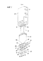
Фиг. 7 представляет собой разобранный схематический вид в перспективе компонентов, относящихся к электромагнитному участку согласно настоящему варианту выполнения.FIG. 7 is an exploded schematic perspective view of components related to the electromagnetic portion according to the present embodiment.
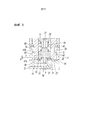
Фиг. 8 представляет собой увеличенный вид в сечении соответствующего участка, взятого вдоль линии VIII-VIII с Фиг. 4.FIG. 8 is an enlarged sectional view of a corresponding portion taken along line VIII-VIII in FIG. 4.
Фиг. 9 представляет собой схематический вид в перспективе рабочего элемента клапана до прикрепления колпачка к опорным рычагам рабочего элемента клапана.FIG. 9 is a schematic perspective view of the valve actuator before the cap is attached to the valve actuator support arms.
Фиг. 10 представляет собой схематический вид в перспективе состояния, следующего за состоянием на Фиг. 9, где направляющие канавки клапанного диска установлены на опорных рычагах.FIG. 10 is a schematic perspective view of a state following the state in FIG. 9 where the valve disc guide grooves are mounted on the support arms.
Фиг. 11 представляет собой схематический вид в перспективе состояния, следующего за состоянием, показанным на Фиг. 10, где колпачок растягивается между опорными рычагами.FIG. 11 is a schematic perspective view of a state following the state shown in FIG. 10 where the cap is stretched between the support arms.
Фиг. 12 представляет собой схематический вид в сечении состояния, где рабочий элемент клапана вмещен в центральное отверстие бобины.FIG. 12 is a schematic cross-sectional view of a state where the valve actuator is received in the central opening of the reel.
Фиг. 13 представляет собой схематический вид сверху отверстия бобины, расположенного ближе к корпусу клапана.FIG. 13 is a schematic top view of the reel opening closer to the valve body.
Фиг. 14 представляет собой увеличенный вид в сечении основного участка, взятого вдоль линии XIV-XIV с Фиг. 1.FIG. 14 is an enlarged sectional view of a main portion taken along line XIV-XIV in FIG. 1.
Фиг. 15 представляет собой схематический вид в перспективе состояния, в котором магнитное кольцо прикреплено к выступу зацепления бобины.FIG. 15 is a schematic perspective view of a state in which the magnetic ring is attached to the bobbin engaging protrusion.
Описание вариантов выполненияDescription of options
[0014][0014]
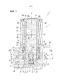
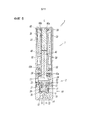
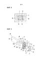
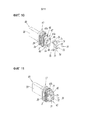
Фиг. 1-15 иллюстрируют электромагнитный клапан согласно одному варианту выполнения настоящего изобретения. Электромагнитный клапан согласно настоящему изобретению в основном включает в себя основной участок 2 клапана, включающий в себя клапанный диск 3 для переключения пути потока, через который под давлением протекает текучая среда, такая как воздух, и электромагнитный участок 7, который приводит в действие клапанный диск 3 основного участка 2 клапана. Основной участок 2 клапана и электромагнитный участок 7 соединены последовательно в направлении оси L электромагнитного клапана 1.FIG. 1-15 illustrate a solenoid valve in accordance with one embodiment of the present invention. The solenoid valve according to the present invention basically includes a
[0015][0015]
Как видно из Фиг. 1 и 2, основной участок 2 клапана включает в себя корпус 10 клапана, имеющий прямоугольное сечение. В первой боковой поверхности корпуса 10 клапана образованы подающий канал P, выходной канал A и выпускной канал R. Клапанная коробка, с которой сообщаются подающий канал P, выходной канал A и выпускной канал R, образована внутри корпуса 10 клапана. К этим каналам прикреплена прокладка 29.As seen in FIG. 1 and 2, the
[0016][0016]
Как показано на Фиг. 1 и Фиг. 4, в клапанной коробке 11 расположены первое седло 12 клапана и второе седло 13 клапана, по направлению к и от которых перемещается клапанный диск 3. Первое седло 12 клапана и второе седло 13 клапана расположены друг напротив друга в направлении оси L. Первое седло 12 клапана расположено на поверхности 14 нижней стенки клапанной коробки 11, чтобы окружать подающее сквозное отверстие 15 в по существу центральном участке поверхности 14 нижней стенки и выступать в сторону электромагнитного участка 7. Подающее сквозное отверстие 15 сообщается с подающим коммуникационным путем 16, образованным ближе к дну корпуса 10 клапана, чем поверхность 14 нижней стенки. Подающий коммуникационный путь 16 соединен с подающим каналом P. Таким образом, подающий канал P сообщается с клапанной коробкой 11 через подающее сквозное отверстие 15.As shown in FIG. 1 and FIG. 4, a
[0017][0017]
С другой стороны, второе седло 13 клапана расположено на фиксаторе 17, прикрепленном к клапанной коробке 11. Фиксатор 17 выполнен из смоляного материала и вмещен в клапанную коробку 11 на участке, находящемся ближе к краю отверстия (ближе к электромагнитному участку 7) клапанной коробки 11, чем клапанный диск 3.Фиксатор 17 включает в себя кольцевой внешний периферийный участок 20, который соответствует внутренней периферийной стенке клапанной коробки 11, и выступ 19, который расположен внутри кольцевого наружного периферийного участка 20, чтобы выступать в направлении первого седла 12 клапана.On the other hand, the
[0018][0018]
Как показано на Фиг. 1 и Фиг. 2, выпускное сквозное отверстие 21, которое сообщается с выпускным каналом R, образовано на участке кончика (вершины) выступа 19 фиксатора 17. Второе седло 13 клапана, имеющее кольцевую форму, расположено вокруг выпускного сквозного отверстия 21. Кольцевая канавка 22 образована в кольцевом внешнем периферийном участке 20. Уплотнительные элементы 23 прикреплены к обеим сторонам кольцевой канавки 22 в направлении оси L для герметичного уплотнения внутренней части клапанной коробки 11. Кольцевая канавка 22 сообщается с выпускным коммуникационным путем 24, сообщающимся с выпускным сквозным отверстием 21. Таким образом, выпускной канал R сообщается с внутренней частью клапанной коробки 11 через кольцевую канавку 22, выпускной коммуникационный путь 24 и выпускное сквозное отверстие 21. Между выступом 19 и кольцевым внешним периферийным участком 20 образована пара вводных отверстий 25, через которые вставлена пара опорных рычагов 45 рабочего элемента 40 клапана, описанного выше (см. Фиг. 1 и Фиг. 9).As shown in FIG. 1 and FIG. 2, an outlet through
[0019][0019]
Как показано на Фиг. 1 и Фиг. 4, клапанный диск 3, который является тарельчатым клапаном, вмещен в клапанную коробку 11 в пространство между первым седлом 12 клапана и вторым седлом 13 клапана. Клапанный диск 3 образован из смоляного материала, имеющего упругость и уплотняющие свойства как у резины, и образован по существу в прямоугольной форме. Клапанный диск 3 перемещается по направлению к и от первого седла 12 клапана и второго седла 13 клапана чтобы изменять состояния соединения между каналами P, A и R. Упругий элемент 26, образованный цилиндрической пружиной, расположен между клапанным диском 3 и фиксатором 17, прикрепленным к корпусу 10 клапана. Упругий элемент 26 постоянно поджимает клапанный диск 3 к первому седлу 12 клапана. Когда электромагнитный участок 7 находится в невозбужденном состоянии (размагниченном состоянии), клапанный диск 3 устанавливается на первое седло 12 клапана побуждающей силой упругого элемента 26 (см. Фиг. 1-3). В настоящем варианте выполнения базовый конец выступа 19 фиксатора 17 функционирует как пружинное седло для упругого элемента 26.As shown in FIG. 1 and FIG. 4, the
[0020][0020]
Как показано на Фиг. 8, клапанный диск 3 включает в себя пару направляющих канавок 3а, которые открыты в противоположных направлениях, на торцевых поверхностях в направлении ширины клапанного диска 3 (направление влево-вправо на Фиг. 8), чтобы продолжаться в направлении оси L. Когда пара опорных рычагов 45 рабочего элемента 40 клапана, описанного ниже, вмещена в направляющие канавки 3a, клапанный диск 3 поддерживается между парой опорных рычагов 45, которые могут скользить в направлении оси L. Эта конструкция, включающая в себя направляющие канавки 3а, может препятствовать перемещению клапанного диска 3 в направлении, перпендикулярном оси рабочего элемента клапана 40, и предотвращать отклонение оси клапанного диска 3. Таким образом, клапанный диск 3 может быть надежно установлен на первом седле 12 клапана и на втором седле 13 клапана.As shown in FIG. 8, the
[0021][0021]
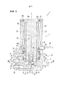
Далее описан электромагнитный участок 7. Как показано на Фиг. 1 и Фиг. 7, электромагнитный участок 7 содержит магнитную крышку 30, имеющую прямоугольное сечение с первым концом (верхний конец на Фиг. 1) в направлении оси L, закрытым колпаком 31. Как показано на Фиг. 1, бобина 60, вокруг которой намотана возбуждающая катушка 32, неподвижный сердечник 35, прикрепленный к центральному отверстию 60а бобины 60, рабочий элемент 40 клапана, вмещенный в центральное отверстие 60а для скольжения в направлении оси L и магнитное кольцо 80, расположенное на конце бобины 60 вблизи корпуса 10 клапана для окружения отверстия центрального отверстия 60a, расположены внутри магнитной крышки 30. Как показано на Фиг. 1 и Фиг. 4, кольцевые канавки 60b образованы между колпаком 31 и бобиной 60, и между бобиной 60 и магнитным кольцом 80. Уплотнительные элементы 38 прикреплены к соответствующим кольцевым канавкам 60В. Пара зажимов катушки 39, электрически соединенных с возбуждающей катушкой 32, выступает из боковой поверхности магнитной крышки 30. Подводящие провода подключены к зажимам 39 катушки.Next, the
[0022][0022]
Неподвижный сердечник 35 выполнен из металлического материала и образован по существу в прямоугольной форме. Неподвижный сердечник 35 включает в себя фланцевые участки 35a на первом конце (верхний конец на Фиг. 1) в направлении оси L. Неподвижный сердечник 35 удерживается между бобиной 60 и колпаком 31, при этом фланцевые участки 35a зацеплены с концевым участком бобины 60 ближе к колпаку 31.The fixed
[0023][0023]
Рабочий элемент 40 клапана включает в себя участок 43 подвижного сердечника, который смещается в направлении оси L в ответ на возбуждающий эффект электромагнитного участка 7. Участок 43 подвижного сердечника расположен напротив неподвижного сердечника 35 и притягивается к неподвижному сердечнику 35 или разносится от него в ответ на возбуждающую катушку 32, находящуюся под напряжением или без напряжения. Рабочий элемент 40 клапана смещается вместе с участком 43 подвижного сердечника в ответ на смещение участка 43 подвижного сердечника в направлении оси L, чтобы заставить клапанный диск 3 избирательно устанавливаться на первом седле 12 клапана или втором седле 13 клапана. Конкретно, в то время, как возбуждающая катушка 32 находится под напряжением (возбужденное состояние), как показано на Фиг. 4-6, рабочий элемент 40 клапана притягивается к неподвижному сердечнику 35, клапанный диск 3 освобождает первое седло 12 клапана для установки на второе седло 13 клапана, так что подающий канал P и выходной канал A сообщаются друг с другом через клапанную коробку 11. В отличие от этого, когда возбуждающая катушка 32 не находится под напряжением (размагниченное состояние), как показано на Фиг. 1-3, то рабочий элемент 40 клапана разнесен от неподвижного сердечника 35 так, что клапанный диск 3 освобождает второе седло 13 клапана, чтобы установиться на первом седле 12 клапана, и чтобы выходной канал A и выпускной канал R сообщались друг с другом через клапанную коробку 11.The
[0024][0024]
Как показано на Фиг. 1 и Фиг. 4, рабочий элемент 40 клапана также включает в себя опорный участок клапана, который поддерживает клапанный диск 3, одновременно позволяя клапанному диску 3 перемещаться в направлении оси L относительно рабочего элемента 40 клапана. Опорный участок клапана включает в себя пару опорных рычагов 45, бесшовно за одно целое продолжающихся от одного конца 43а участка 43 подвижного сердечника в направлении оси L. Опорный участок клапана имеет дальний конец и базовый конец с обеих сторон в направлении от оси L. Базовый конец опорного участка клапана, то есть базовые концы опорных рычагов 45, соединены с одним концом 43а участка 43 подвижного сердечника в направлении оси L. Эти опорные рычаги 45 расположены бок о бок на обоих концах рабочего элемента 40 клапана в направлении ширины (направление влево-вправо на Фиг. 1), чтобы быть двусторонне симметричными относительно оси L. Рабочий элемент 40 клапана образован из одной магнитной металлической пластины. Пробиванием этой металлической пластины, участок 43 подвижного сердечника и опорный участок клапана (то есть, опорные рычаги 45) образованы за одно целое. Таким образом, как показано на Фиг. 2 или Фиг. 9-11, пара поверхностей 50, параллельных друг другу с обеих сторон в направлении толщины рабочего элемента 40 клапана (направление влево-вправо на Фиг. 2), являются одиночными плоскими поверхностями, непрерывно продолжающимися от участка 43 подвижного сердечника до опорных рычагов 45.As shown in FIG. 1 and FIG. 4, the
[0025][0025]
Как показано на Фиг. 1 и Фиг. 4, пара опорных рычагов 45 продолжается в клапанную коробку 11 корпуса 10 клапана через пару вводных отверстий 25, открытых в фиксаторе 17 и внутри клапанной коробки 11, соответствующих паре направляющих канавок 3а (см. Фиг. 8), образованных в клапанном диске 3, способных смещаться в направлении оси L относительно клапанного диска 3. Таким образом, клапанный диск 3 поддерживается между парой опорных рычагов 45 для скольжения в направлении оси L. Вместо того чтобы прикрепляться к рабочему элементу 40 клапана, клапанный диск 3 поддерживается с возможностью перемещения рабочим элементом 40 клапана так, что опорный участок клапана рабочего элемента 40 клапана может быть сконструирован более свободно и получать более простую конструкцию или форму.As shown in FIG. 1 and FIG. 4, a pair of
[0026][0026]
Как показано на Фиг. 3 и Фиг. 6, пара опорных рычагов 45 соответственно включает в себя на своих дальних концевых участках крючки зацепления 47, выступающие в направлениях друг от друга. Каждый из крючков зацепления 47 имеет наклонную поверхность 47а на дальнем концевом участке. Наклонная поверхность 47а постепенно наклоняется к оси L по мере продолжения к дальней концевой поверхности 46 соответствующего опорного рычага 45. Каждый из крючков зацепления 47 имеет поверхность зацепления 47В, образованную из концевой поверхности, перпендикулярной оси L, в базовой концевой части.As shown in FIG. 3 and FIG. 6, a pair of
[0027][0027]
Как показано на Фиг. 3, Фиг. 6 и Фиг. 9, колпачок 70 вытягивается между дальними концевыми участками пары опорных рычагов 45. Колпачок 70 образован из эластичной тонкой металлической пластины, имеющей по существу U-образное сечение. Колпачок 70 имеет пару отверстий зацепления 71, зацепленных за крючки зацепления 47, и отверстие 72 клапана, расположенное между парой отверстий зацепления 71. Клапанный диск 3 установлен на первом седле 12 клапана через отверстие 72 клапана.As shown in FIG. 3, FIG. 6 and FIG. 9, the
[0028][0028]
Как показано на Фиг. 9, колпачок 70 включает в себя тонкий пластинчатый участок 73 зацепления, продолжающийся в направлении, перпендикулярном оси L и эластичный в направлении оси L, и пару запорных участков 74, продолжающихся от левого и правого концов участка 73 зацепления в направлении, по существу перпендикулярном участку 73 зацепления колпачка. Соединительные участки между участком 73 зацепления колпачка и запорными участками 74 плавно изогнуты по дуге. Когда рабочий элемент 40 клапана притягивается к неподвижному сердечнику 35, участок 73 зацепления колпачка зацеплен с участком 4 зацепления клапанного диска 3, установленным на первом седле 12 клапана, то есть концевой поверхности клапана, обращенной к первому седлу 12 клапана, как показано на Фиг. 6. Таким образом, клапанный диск 3 отделен от первого седла 12 клапана за счет побуждающей силы упругого элемента 26 и установлен на второе седло 13 клапана. Участок 73 зацепления колпачка имеет отверстие 72 клапана, имеющее по существу круглый открытый край. Как показано на Фиг. 3, клапанный диск 3 может быть установлен на первом седле 12 клапана через отверстие 72 клапана.As shown in FIG. 9, the
[0029][0029]
Отверстия зацепления 71 являются прямоугольными и образованы на участках через участок 73 зацепления колпачка и запорные участки 74. Согнутые участки 75, согнутые наружу, образованы на дальних концах запорных участков 74. Как описано выше, в этом варианте выполнения колпачок 70 образован из металлической тонкой пластины и имеет простую конструкцию, позволяющую крепление клапанного диска 3 на опорном участке рабочего элемента 40 клапана и образование участка 73 зацепления колпачка.The engaging
[0030][0030]
Колпачок 70 прикреплен между опорными рычагами 45 следующим образом. Во-первых, как показано на Фиг. 9, рабочий элемент 40 клапана, фиксатор 17, упругий элемент 26, клапанный диск 3 и колпачок 70 подготовлены. Упругий элемент 26, образованный из цилиндрической пружины, прикреплен к внешней окружности выступа 19 фиксатора 17. После этого рабочий элемент 40 клапана и фиксатор 17, к которому прикреплен упругий элемент 26, имеют свои оси, выровненные друг с другом, и пару опорных рычагов 45, введенных во вводные отверстия 25 фиксатора 17 с одной стороны фиксатора 17 в направление оси L (сторона, противоположная выступу 19). Одновременно клапанный диск 3 прижимается к фиксатору 17 за счет побуждающей силы упругого элемента 26 от противоположной стороны к рабочему элементу 40 клапана (опорные рычаги 45) (со стороны выступа 19). Таким образом, направляющие канавки 3а клапанного диска 3 соответствуют паре опорных рычагов 45, продолжающихся от вводных отверстий 25 (см. Фиг. 10). В таком состоянии, колпачок 70 прикреплен между опорными рычагами 45.The
[0031][0031]
Здесь, как показано на Фиг. 10, когда колпачок 70 прижат к опорным рычагам 45, при этом сторона отверстия (сторона запорных участков 74) колпачка 70 обращена к дальним концевым поверхностям 46 опорных рычагов 45, то изогнутые участки 75 пары запорных участков 74 колпачка 70 перемещают наклонные поверхности 47а крючков 47 зацепления к дальним концевым участкам опорных рычагов 45. Таким образом, расстояние между парой запирающих участков 74 упруго увеличено. Затем края отверстия (свободные концы) отверстий 71 зацепления запорных участков 74 смещены в положения поверхностей 47b зацепления крючков 47 зацепления, а положения отверстий 71 зацепления и положения крючков 47 зацепления выровнены друг с другом. Таким образом, увеличенные запорные участки 74 восстанавливаются в упругости, и крючки 47 зацепления соответствуют отверстиям 71 зацепления, как показано на Фиг. 11. Таким образом, колпачок 70 прикрепляется к опорным рычагам 45. В это время, положение участка 73 зацепления колпачка 70 в направлении оси L находится между позициями дальних концевых поверхностей 46 опорных рычагов 45 и позицией участка 4 зацепления клапанного диска 3.Here, as shown in FIG. 10, when the
[0032][0032]
Как показано на Фиг. 3, Фиг. 4 или Фиг. 6, дальние концевые поверхности 46 пары опорных рычагов 45 представляют собой плоские поверхности, перпендикулярные оси L. Дальние концевые поверхности 46 образуют позиционирующие поверхности, обращенные в направлении, в котором упругий элемент 26 поджимает клапанный диск 3, то есть к первому седлу 12 клапана. С другой стороны, в клапанной коробке 11 пара контактных поверхностей 27 вперед и в сторону от которых дальние концевые поверхности 46 перемещаются со сдвигом участка 43 подвижного сердечника, расположены на поверхности 14 нижней стенки, обращенной к этим дальним концевым поверхностям 46. Пара контактных поверхностей 27 представляет собой плоские поверхности, параллельные дальним концевым поверхностям 46 опорных рычагов 45. Контактные поверхности 27 расположены на обеих сторонах первого седла 12 клапана, то есть по обеим сторонам корпуса 10 клапана в направлении ширины (направление влево-вправо на Фиг. 3) и выступают в сторону электромагнитного участка 7. Высота контактных поверхностей 27, с помощью которых контактные поверхности 27 выступают из поверхности 14 нижней стенки в клапанной коробке 11, меньше, чем высота, на которую первое седло 12 клапана выступает из поверхности 14 нижней стенки в клапанную коробку 11. В частности, контактные поверхности 27 находятся ближе к поверхности 14 нижней стенки, чем первое седло 12 клапана.As shown in FIG. 3, FIG. 4 or FIG. 6, the distal end surfaces 46 of the pair of
[0033][0033]
Как показано на Фиг. 1 и Фиг. 3, когда рабочий элемент 40 клапана смещается в направлении, в котором сжимается упругий элемент 26 так, что клапанный диск 3 устанавливается на первое седло 12 клапана, дальние концевые поверхности 46 пары опорных рычагов 45 стыкуются с контактными поверхностями 27. В то же время, как показано на Фиг. 3, участок 73 зацепления колпачка 70 не контактирует с участком 4 зацепления клапанного диска 3 и образуется зазор G, меньший, чем ход рабочего элемента 40 клапана, между участком 73 зацепления колпачка и участком 4 зацепления.As shown in FIG. 1 and FIG. 3, when the
[0034][0034]
Как показано на Фиг. 12, центральное отверстие 60а бобины 60, вмещающее рабочий элемент 40 клапана, имеет по существу прямоугольное сечение, имеющее пару первых внутренних поверхностей 61 и пару вторых внутренних поверхностей 65. Первые внутренние поверхности 61 обращены к двум поверхностям 50 с обеих сторон рабочего элемента 40 клапана в направлении толщины, а вторые внутренние поверхности 65 обращены к двум боковым концевым поверхностям 51, параллельным друг другу и на обоих концах рабочего элемента 40 клапана (участок 43 подвижного сердечника) в направлении ширины (направление вправо-влево на Фиг. 12).As shown in FIG. 12, the
[0035][0035]
На обоих боковых участках 62 пары первых внутренних поверхностей 61 в направлении ширины ступенчатые участки 64 образованы таким образом, чтобы расстояние между первыми внутренними поверхностями 61 стало меньше расстояния между промежуточными участками 63, удерживаемыми между обоими боковыми участками 62. Ступенчатые участки 64 продолжаются в направлении оси L и соединены со вторыми внутренними поверхностями 65 от обоих боковых участков 62 первых боковых поверхностей 61 в окружном направлении центрального отверстия 60a. Пара выпуклых резьб 66 образована на паре вторых внутренних поверхностей 65, чтобы продолжаться в направлении оси L. Выпуклые резьбы 66 образованы на вторых внутренних поверхностях 65 так, чтобы быть обращенными друг к другу (лицевой стороной внутрь) и иметь дугообразное сечение.In both
[0036][0036]
Когда участок 43 подвижного сердечника рабочего элемента 40 клапана вставлен в центральное отверстие 60а бобины 60, пара боковых концевых поверхностей 51 поддерживаются парой выпуклых резьб 66 для скольжения в направлении оси L, и пара поверхностей 50 поддерживается ступенчатыми участками 64 для скольжения в направлении оси L. Рабочий элемент 40 клапана продолжается через магнитное кольцо 80, чтобы его дальний конец выступал в направлении корпуса 10 клапана. В настоящем варианте выполнения обе боковые концевые поверхности 51 рабочего элемента клапана 40 и оба боковых участка пары поверхностей 50 поддерживаются выпуклыми резьбами 66 и ступенчатыми участками 64, которые могут скользить в центральном отверстии 60а бобины 60. Таким образом, ось рабочего элемента 40 клапана эффективно предотвращает отклонения.When the
[0037][0037]
Как показано на Фиг. 7 и Фиг. 13-15, пара выступающих стенок 67 зацепления расположена в отверстии центрального отверстия 60а, обращенного к корпусу 10 клапана. Выступающие стенки 67 зацепления продолжаются от пары вторых внутренних поверхностей 65 в направлении оси L. Магнитное кольцо 80, расположенное вокруг центрального отверстия 60а, имеет участок 81 зацепления. Когда выступающие стенки 67 зацепления вмещаются в участок 81 отверстия зацепления, магнитное кольцо 80 позиционируется коаксиально с бобиной 60.As shown in FIG. 7 and FIG. 13-15, a pair of protruding
[0038][0038]
Как показано на Фиг. 7 и Фиг. 13-15, каждая выступающая стенка 67 зацепления бобины 60 включает в себя участок 68 боковой стенки, обращенный к обоим боковым концевым поверхностям 51 рабочего элемента 40 клапана, и полукруглые дугообразные участки 69 стенки с обеих сторон (верхняя и нижняя стороны на Фиг. 13) участка 68 боковой стенки. С другой стороны, как показано на Фиг. 7, Фиг. 14 и Фиг. 15, участок 81 отверстия зацепления магнитного кольца 80 имеет пару первых участков 82 поверхности, продолжающихся параллельно друг другу, чтобы быть обращенными к паре поверхностей 50 рабочего элемента клапана 40 и вторым участкам 83 поверхности с обеих сторон первых участков 82 поверхности. Расстояние между первыми участками поверхности 82 больше, чем толщина рабочего элемента клапана 40 (расстояние между парой поверхностей 50) и расстояние между промежуточными участками 63 первых внутренних поверхностей 61 центрального отверстия 60а. Каждый второй участок 83 поверхности включает в себя прямой участок 84, с которым зацеплена выступающая стенка 67 зацепления и который проходит в направлении, перпендикулярном к первому участку 82 поверхности, и полукруглые дугообразные участки 85 с обеих сторон прямого участка 84. Прямой участок 84 зацеплен с внешней периферической поверхностью участка 68 боковой стенки, соответствующей выступающей стенки 67 зацепления. Дугообразные участки 85 зацеплены с внешними периферическими поверхностями дугообразных концевых участков 69 выступающей стенки 67 зацепления.As shown in FIG. 7 and FIG. 13-15, each protruding
[0039][0039]
Как показано на Фиг. 14, магнитное кольцо 80 имеет внешнюю периферическую поверхность по существу прямоугольную на виде сверху, и пару выемок 86 на обеих боковых поверхностях внешней периферической поверхности в направлении ширины. Пара выемок 86 зацеплена с парой внутренних выступов 28, расположенных в клапанной коробке 11 корпуса 10 клапана. Как описано выше, когда магнитное кольцо 80 прикреплено к отверстию центрального отверстия 60а, как показано на Фиг. 14, то выступающие стенки 67 зацепления бобины 60 и участки 81 отверстия зацепления магнитного кольца 80 зацепляются друг с другом, и выемки 86 и внутренние выступы 28 зацепляются друг с другом. Таким образом, магнитное кольцо 80 и центральное отверстие 60a бобины 60 имеют оси, выровненные друг с другом. Когда магнитное кольцо 80 прикрепляется к отверстию бобины 60, выступающие стенки 67 зацепления располагаются между обоими боковыми концевым поверхностям 51 рабочего элемента 40 клапана и вторыми участками 83 поверхности магнитного кольца 80. В этом состоянии образуется зазор между каждым из первых участков 82 поверхности магнитного кольца 80 и соответствующей поверхностью 50 рабочего элемента 40 клапана. Эта конструкция предотвращает непосредственный контакт друг с другом рабочего элемента 40 клапана и магнитного кольца 80. Таким образом, эффективность электромагнитного участка 7 надежно предотвращается от снижения.As shown in FIG. 14, the
[0040][0040]
В электромагнитном клапане 1, имеющем вышеописанную конструкцию, в то время как возбуждающая катушка 32 не находится под напряжением (размагниченное состояние), как показано на Фиг. 1 и Фиг. 2, рабочий элемент 40 клапана отделен от неподвижного сердечника 35. В то время как возбуждающая катушка 32 находится в размагниченном состоянии, клапанный диск 3 устанавливается на первом седле 12 клапана побуждающей силой упругого элемента 26, установленного на нем через фиксатор 17, чтобы блокировать связь между подающим каналом P и клапанной коробкой 11. В это время второе седло 13 клапана, расположенное напротив первого седла 12 клапана в направлении оси L, открыто, а выходной канал А сообщается с выпускным каналом R через выпускное сквозное отверстие 21 и выпускной путь 24 связи в клапанной коробке 11. Таким образом, текучая среда, находящаяся под давлением в клапанной коробке 11, выпускается наружу через выпускной канал R, соединенный снаружи.In the
[0041][0041]
В настоящем варианте выполнения, в то время как возбуждающая катушка 32 находится в размагниченном состоянии, как показано на Фиг. 3, опорная часть клапана рабочего элемента 40 клапана, то есть пара опорных рычагов 45, имеет свои дальние концевые поверхности 46, стыкующиеся с парой контактных поверхностей 27 поверхности 14 нижней стенки клапанной коробки 11. Клапанный диск 3 установлен на первом седле 12 клапана в отверстии 72 колпачка 70 между парой опорных рычагов 45. В это время поверхность конца седла клапана (участок 4 зацепления) клапанного диска 3, обращенная к первому седлу 12 клапана и участку 73 зацепления колпачка 70, не контактируют друг с другом, и между участком 4 зацепления и участком 73 зацепления колпачка образуется зазор G, меньший, чем ход рабочего элемента 40 клапана.In the present embodiment, while the
[0042][0042]
Когда возбуждающая катушка 32 в этом состоянии под напряжением находится в возбужденном состоянии, рабочий элемент 40 клапана притягивается к неподвижному сердечнику 35 и смещается к неподвижному сердечнику 35 в направлении оси L за счет побуждающей силы упругого элемента 26, который поджимает клапанный диск 3 к первому седлу 12 клапана, как показано на Фиг. 4-6. Как показано на Фиг. 6, при смещении рабочего элемента 40 клапана в направлении оси L пара опорных рычагов 45 рабочего элемента 40 клапана разнесена на расстояние от контактных поверхностей 27, а участок 73 зацепления колпачка 70, прикрепленного между опорными рычагами 45, зацепляется с участком 4 зацепления клапанного диска 3. Клапанный диск 3, установленный на первом седле 12 клапана, смещается в направлении второго седла 13 клапана, имея направляющие канавки 3а, поддерживаемые опорными рычагами 45.When the
[0043][0043]
Как описано выше, зазор G образован между участком 4 зацепления клапанного диска 3 и участком 73 зацепления колпачка 70. Таким образом, когда возбуждающая катушка 32 переключается в возбужденное состояние, вместо дискового клапана 3, смещенного в направлении второго седла 13 клапана одновременно с сдвигом рабочего элемента клапана 40, зазор G между участком 4 зацепления и участком 73 зацепления колпачка сначала сжимается, а после того, как зазор G уменьшается до нуля, участок 73 зацепления колпачка входит в зацепление с участком 4 зацепления клапанного диска 3, а затем клапанный диск 3 перемещается ко второму седлу 13 клапана.As described above, a gap G is formed between the engaging
[0044][0044]
Притяжением рабочего элемента 40 клапана клапанный диск 3 устанавливается на второе седло 13 клапана, чтобы закрыть выпускное сквозное отверстие 21 и отпустить первое седло 12 клапана, обращенное ко второму седлу 13 клапана. Следовательно, подающий канал P сообщается с выходным каналом A через подающее сквозное отверстие 15 и клапанную коробку 11, и текучая среда под давлением, подаваемая из подающего канала P, выводится через выходной канал A (см. Фиг. 4-6). Здесь участок 73 зацепления колпачка 70, расположенный на паре опорных рычагов 45, выполнен из тонкой пластины, эластичной в направлении оси L. Когда клапанный диск 3 установлен на втором седле 13 клапана, сила, воздействующая на клапанный диск 3 в направлении оси L, может быть поглощена участком 73 зацепления колпачка. Эта конструкция может препятствовать износу или необратимой деформации клапанного диска 3 (перманентной деформации) такой силой, которая неоднократно воздействует на клапанный диск 3.By pulling on the
[0045][0045]
Когда возбуждающая катушка 32 перестает находиться под напряжением для переключения в размагниченное состояние, показанное на Фиг. 1-3, рабочий элемент 40 клапана разносится от неподвижного сердечника 35 и клапанный диск 3 разносится на расстояние от второго седла 13 клапана побуждающей силой упругого элемента 26. Как описано выше, клапанный диск 3 закрывает первое седло 12 клапана и освобождает второе седло 13 клапана, так что выходной канал А сообщается с выпускным каналом R через клапанную коробку 11 и подвергается воздействию атмосферы. В это время плоские дальние концевые поверхности 46 пары опорных рычагов 45 стыкуются с парой контактных поверхностей 27, которые параллельны дальним концевым поверхностям 46, так что рабочий элемент 40 клапана точно располагается относительно корпуса 10 клапана. Таким образом, чувствительность электромагнитного клапана можно контролировать более точно.When the
[0046][0046]
Когда дальние концевые поверхности 46 опорных рычагов 45 стыкуются с контактными поверхностями 27, клапанный диск 3 устанавливается на первом седле 12 клапана, при этом образуется зазор G между участком 4 зацепления, обращенным к первому седлу 12 клапана и участком 73 зацепления колпачка 70. Электромагнитный клапан 1 согласно настоящему варианту выполнения, имеющий эту конструкцию, может препятствовать непосредственному воздействию кинетической энергии рабочего элемента 40 клапана на клапанный диск 3, когда клапанный диск 3 установлен на первом седле 12 клапана и, таким образом, может уменьшать внешнюю силу, действующую на клапанный диск 3 в направлении оси L. Таким образом, клапанный диск 3 можно предотвращать от износа или необратимой деформации (перманентной деформации) такой внешней силой, которая неоднократно воздействует на клапанный диск 3, так что размер клапанного диска 3 в направлении оси L можно предотвращать от изменения с течением времени. Следовательно, ход рабочего элемента клапана 40, то есть расстояние от первого седла 12 клапана до клапанного диска 3, можно предотвращать от изменения. Таким образом, скорость потока текучей среды, протекающей через седло 12 клапана, или чувствительность электромагнитного клапана, можно предотвращать от изменения, насколько это возможно.When the distal end surfaces 46 of the
[0047][0047]
До сих пор электромагнитный клапан в соответствии с настоящим изобретением был описан. Однако изобретение по настоящей заявке не ограничивается вышеуказанным вариантом и может, естественно, изменяться в конструкции различными способами в пределах объема, не отходящего от сути формулы изобретения. Например, в представленном варианте выполнения рабочий элемент 40 клапана, или участок 43 подвижного сердечника и опорный участок клапана (опорные рычаги 45) образованы штамповкой одной металлической пластины. Однако, поскольку участок 43 подвижного сердечника является магнитным и может привлекаться к неподвижному сердечнику 35 и разноситься от него, опорные участки 45 клапана могут быть образованы из отдельных элементов, выполненных за одно целое. Кроме того, хотя в вышеуказанном варианте выполнения описан трехканальный электромагнитный клапан, количество каналов этим не ограничено и может составлять два.So far, a solenoid valve according to the present invention has been described. However, the invention of the present application is not limited to the above embodiment and can, of course, be varied in design in various ways within the scope that does not depart from the essence of the claims. For example, in the illustrated embodiment, the
Список ссылочных позицийList of reference positions
[0048][0048]
1 электромагнитный клапан1 solenoid valve
3 клапанный диск3 valve disc
4 участок зацепления4 area of engagement
7 электромагнитный участок7 electromagnetic section
10 корпус клапана10 valve body
11 клапанная коробка11 valve box
12 первое седло клапана12 first valve seat
13 второе седло клапана13 second valve seat
14 поверхность нижней стенки14 bottom wall surface
26 упругий элемент26 elastic element
27 контактная поверхность27 contact surface
40 рабочий элемент клапана40 valve working element
43 железный сердечник43 iron core
43a концевая поверхность43a end surface
45 опорный рычаг (опорный участок клапана)45 support arm (valve support section)
46 дальняя концевая поверхность46 far end surface
73 участок зацепления колпачка73 cap engagement area
А выходной каналAnd the output channel
P подающий каналP supply channel
R выпускной канал.R outlet port.
Claims (26)
Applications Claiming Priority (3)
| Application Number | Priority Date | Filing Date | Title |
|---|---|---|---|
| JP2016100914A JP6732202B2 (en) | 2016-05-19 | 2016-05-19 | solenoid valve |
| JP2016-100914 | 2016-05-19 | ||
| PCT/JP2017/017639 WO2017199804A1 (en) | 2016-05-19 | 2017-05-10 | Solenoid valve |
Publications (3)
| Publication Number | Publication Date |
|---|---|
| RU2018144812A RU2018144812A (en) | 2020-06-19 |
| RU2018144812A3 RU2018144812A3 (en) | 2020-08-03 |
| RU2733142C2 true RU2733142C2 (en) | 2020-09-29 |
Family
ID=60325831
Family Applications (1)
| Application Number | Title | Priority Date | Filing Date |
|---|---|---|---|
| RU2018144812A RU2733142C2 (en) | 2016-05-19 | 2017-05-10 | Solenoid valve |
Country Status (10)
| Country | Link |
|---|---|
| US (1) | US10781935B2 (en) |
| JP (1) | JP6732202B2 (en) |
| KR (1) | KR102262070B1 (en) |
| CN (1) | CN109154401B (en) |
| BR (1) | BR112018072418A2 (en) |
| DE (1) | DE112017002551T5 (en) |
| MX (1) | MX2018014192A (en) |
| RU (1) | RU2733142C2 (en) |
| TW (1) | TWI731075B (en) |
| WO (1) | WO2017199804A1 (en) |
Families Citing this family (2)
| Publication number | Priority date | Publication date | Assignee | Title |
|---|---|---|---|---|
| JP7089242B2 (en) * | 2018-09-21 | 2022-06-22 | Smc株式会社 | solenoid valve |
| CN114352768B (en) * | 2020-09-28 | 2024-01-05 | 青岛海尔电冰箱有限公司 | Refrigerating system and refrigerator |
Citations (5)
| Publication number | Priority date | Publication date | Assignee | Title |
|---|---|---|---|---|
| JP2000199411A (en) * | 1998-11-04 | 2000-07-18 | Mikuni Corp | Valve drive device |
| JP2003172470A (en) * | 2001-12-04 | 2003-06-20 | Smc Corp | Solenoid valve |
| RU98517U1 (en) * | 2010-05-27 | 2010-10-20 | Общество с ограниченной ответственностью Научно-производственное предприятие "Технопроект" | SOLENOID VALVE |
| RU2477408C2 (en) * | 2010-10-13 | 2013-03-10 | Закрытое акционерное общество Производственная компания "Промконтроллер" | Electromagnetic shutoff valve |
| JP2013142470A (en) * | 2012-01-13 | 2013-07-22 | Toto Ltd | Solenoid valve |
Family Cites Families (24)
| Publication number | Priority date | Publication date | Assignee | Title |
|---|---|---|---|---|
| US3107893A (en) * | 1961-08-31 | 1963-10-22 | Robbins Aviat Inc | Solenoid actuated fluid valve |
| US3295079A (en) * | 1964-12-03 | 1966-12-27 | Honeywell Inc | Solenoid actuator assembly having a unitary spring clip for the plunger |
| GB1433034A (en) * | 1972-05-26 | 1976-04-22 | Kernforschung Gmbh Ges Fuer | Glandless electromagnetic valve |
| JPS612865Y2 (en) * | 1980-04-30 | 1986-01-29 | ||
| JPS59146671U (en) * | 1983-03-22 | 1984-10-01 | エスエムシ−株式会社 | Poppet type direct acting solenoid valve |
| JPS6056875U (en) * | 1983-09-26 | 1985-04-20 | エスエムシ−株式会社 | Direct acting 2 port solenoid valve |
| JPS6411484U (en) * | 1987-07-10 | 1989-01-20 | ||
| JPH09196205A (en) | 1996-01-11 | 1997-07-29 | Smc Corp | 3-port valve |
| JP4484188B2 (en) * | 2001-01-12 | 2010-06-16 | 株式会社鷺宮製作所 | High durability solenoid valve |
| JP2003059715A (en) | 2001-08-13 | 2003-02-28 | Smc Corp | Electromagnetic valve solenoid |
| JP3857094B2 (en) * | 2001-09-04 | 2006-12-13 | Smc株式会社 | solenoid valve |
| JP3863745B2 (en) * | 2001-09-04 | 2006-12-27 | Smc株式会社 | solenoid valve |
| DE60208965T2 (en) | 2001-12-04 | 2006-08-17 | Smc K.K. | Electromagnetic valve |
| JP3833525B2 (en) | 2001-12-04 | 2006-10-11 | Smc株式会社 | solenoid valve |
| US7163188B1 (en) * | 2004-07-30 | 2007-01-16 | Emerson Electric Co. | Solenoid valve for fluid flow |
| US7828265B2 (en) * | 2004-07-30 | 2010-11-09 | Emerson Electric Co. | Solenoid valve |
| JP2008157352A (en) * | 2006-12-22 | 2008-07-10 | Smc Corp | Solenoid valve |
| KR200440725Y1 (en) | 2007-02-06 | 2008-06-27 | 신영제어기 주식회사 | Poppet-type direct-acting solenoid-operated valve having buffer unit |
| JP4362853B2 (en) * | 2007-06-18 | 2009-11-11 | Smc株式会社 | 2-port solenoid valve |
| JP2011133071A (en) * | 2009-12-25 | 2011-07-07 | Ckd Corp | Self-holding solenoid valve |
| JP5486987B2 (en) * | 2010-03-31 | 2014-05-07 | Ckd株式会社 | Balance poppet type solenoid valve |
| JP5684088B2 (en) * | 2011-10-20 | 2015-03-11 | 藤倉ゴム工業株式会社 | Flow regulator |
| EP3014533A4 (en) | 2013-06-27 | 2016-11-09 | Picosun Oy | Anti-counterfeit signature |
| JP5938378B2 (en) | 2013-09-18 | 2016-06-22 | Ckd株式会社 | solenoid valve |
-
2016
- 2016-05-19 JP JP2016100914A patent/JP6732202B2/en active Active
-
2017
- 2017-05-03 TW TW106114676A patent/TWI731075B/en active
- 2017-05-10 RU RU2018144812A patent/RU2733142C2/en active
- 2017-05-10 BR BR112018072418-1A patent/BR112018072418A2/en not_active IP Right Cessation
- 2017-05-10 US US16/300,999 patent/US10781935B2/en active Active
- 2017-05-10 WO PCT/JP2017/017639 patent/WO2017199804A1/en active Application Filing
- 2017-05-10 DE DE112017002551.6T patent/DE112017002551T5/en active Pending
- 2017-05-10 KR KR1020187035109A patent/KR102262070B1/en active IP Right Grant
- 2017-05-10 MX MX2018014192A patent/MX2018014192A/en unknown
- 2017-05-10 CN CN201780030742.0A patent/CN109154401B/en active Active
Patent Citations (5)
| Publication number | Priority date | Publication date | Assignee | Title |
|---|---|---|---|---|
| JP2000199411A (en) * | 1998-11-04 | 2000-07-18 | Mikuni Corp | Valve drive device |
| JP2003172470A (en) * | 2001-12-04 | 2003-06-20 | Smc Corp | Solenoid valve |
| RU98517U1 (en) * | 2010-05-27 | 2010-10-20 | Общество с ограниченной ответственностью Научно-производственное предприятие "Технопроект" | SOLENOID VALVE |
| RU2477408C2 (en) * | 2010-10-13 | 2013-03-10 | Закрытое акционерное общество Производственная компания "Промконтроллер" | Electromagnetic shutoff valve |
| JP2013142470A (en) * | 2012-01-13 | 2013-07-22 | Toto Ltd | Solenoid valve |
Also Published As
| Publication number | Publication date |
|---|---|
| JP2017207159A (en) | 2017-11-24 |
| CN109154401A (en) | 2019-01-04 |
| US10781935B2 (en) | 2020-09-22 |
| RU2018144812A (en) | 2020-06-19 |
| KR20190007441A (en) | 2019-01-22 |
| MX2018014192A (en) | 2019-02-25 |
| KR102262070B1 (en) | 2021-06-08 |
| RU2018144812A3 (en) | 2020-08-03 |
| US20190277421A1 (en) | 2019-09-12 |
| DE112017002551T5 (en) | 2019-02-21 |
| JP6732202B2 (en) | 2020-07-29 |
| BR112018072418A2 (en) | 2019-02-19 |
| TWI731075B (en) | 2021-06-21 |
| CN109154401B (en) | 2021-03-26 |
| TW201812200A (en) | 2018-04-01 |
| WO2017199804A1 (en) | 2017-11-23 |
Similar Documents
| Publication | Publication Date | Title |
|---|---|---|
| US7523763B2 (en) | Three-port electromagnetic valve | |
| US20220128165A1 (en) | Gas solenoid valve | |
| RU2728545C2 (en) | Solenoid valve | |
| EP1318340B1 (en) | Solenoid-operated valve | |
| RU2733142C2 (en) | Solenoid valve | |
| US8893747B2 (en) | Valve with an actuator | |
| US9062778B2 (en) | Valve having a diaphragm capable of displacement within a retaining member | |
| US8757207B2 (en) | Solenoid valve | |
| JP2017207158A5 (en) | ||
| KR100447349B1 (en) | Solenoid for electromagnetic valve | |
| JP3825311B2 (en) | solenoid valve | |
| JP2017207159A5 (en) | ||
| JP5033317B2 (en) | Valve mechanism | |
| KR101547950B1 (en) | High speed response solenoid valve | |
| CN111102395A (en) | Solenoid valve and method for operating a solenoid valve | |
| JP3833525B2 (en) | solenoid valve | |
| JPH0328221Y2 (en) | ||
| EP3633252A1 (en) | Electromagnetic fluid valve | |
| CN114623258A (en) | Reversing valve |