RU2728545C2 - Solenoid valve - Google Patents
Solenoid valve Download PDFInfo
- Publication number
- RU2728545C2 RU2728545C2 RU2018144577A RU2018144577A RU2728545C2 RU 2728545 C2 RU2728545 C2 RU 2728545C2 RU 2018144577 A RU2018144577 A RU 2018144577A RU 2018144577 A RU2018144577 A RU 2018144577A RU 2728545 C2 RU2728545 C2 RU 2728545C2
- Authority
- RU
- Russia
- Prior art keywords
- valve
- pair
- movable core
- valve seat
- engaging
- Prior art date
Links
Images
Classifications
-
- F—MECHANICAL ENGINEERING; LIGHTING; HEATING; WEAPONS; BLASTING
- F16—ENGINEERING ELEMENTS AND UNITS; GENERAL MEASURES FOR PRODUCING AND MAINTAINING EFFECTIVE FUNCTIONING OF MACHINES OR INSTALLATIONS; THERMAL INSULATION IN GENERAL
- F16K—VALVES; TAPS; COCKS; ACTUATING-FLOATS; DEVICES FOR VENTING OR AERATING
- F16K31/00—Actuating devices; Operating means; Releasing devices
- F16K31/02—Actuating devices; Operating means; Releasing devices electric; magnetic
- F16K31/06—Actuating devices; Operating means; Releasing devices electric; magnetic using a magnet, e.g. diaphragm valves, cutting off by means of a liquid
- F16K31/0644—One-way valve
- F16K31/0655—Lift valves
-
- F—MECHANICAL ENGINEERING; LIGHTING; HEATING; WEAPONS; BLASTING
- F16—ENGINEERING ELEMENTS AND UNITS; GENERAL MEASURES FOR PRODUCING AND MAINTAINING EFFECTIVE FUNCTIONING OF MACHINES OR INSTALLATIONS; THERMAL INSULATION IN GENERAL
- F16K—VALVES; TAPS; COCKS; ACTUATING-FLOATS; DEVICES FOR VENTING OR AERATING
- F16K31/00—Actuating devices; Operating means; Releasing devices
- F16K31/02—Actuating devices; Operating means; Releasing devices electric; magnetic
- F16K31/06—Actuating devices; Operating means; Releasing devices electric; magnetic using a magnet, e.g. diaphragm valves, cutting off by means of a liquid
-
- B—PERFORMING OPERATIONS; TRANSPORTING
- B60—VEHICLES IN GENERAL
- B60T—VEHICLE BRAKE CONTROL SYSTEMS OR PARTS THEREOF; BRAKE CONTROL SYSTEMS OR PARTS THEREOF, IN GENERAL; ARRANGEMENT OF BRAKING ELEMENTS ON VEHICLES IN GENERAL; PORTABLE DEVICES FOR PREVENTING UNWANTED MOVEMENT OF VEHICLES; VEHICLE MODIFICATIONS TO FACILITATE COOLING OF BRAKES
- B60T8/00—Arrangements for adjusting wheel-braking force to meet varying vehicular or ground-surface conditions, e.g. limiting or varying distribution of braking force
- B60T8/32—Arrangements for adjusting wheel-braking force to meet varying vehicular or ground-surface conditions, e.g. limiting or varying distribution of braking force responsive to a speed condition, e.g. acceleration or deceleration
- B60T8/34—Arrangements for adjusting wheel-braking force to meet varying vehicular or ground-surface conditions, e.g. limiting or varying distribution of braking force responsive to a speed condition, e.g. acceleration or deceleration having a fluid pressure regulator responsive to a speed condition
- B60T8/36—Arrangements for adjusting wheel-braking force to meet varying vehicular or ground-surface conditions, e.g. limiting or varying distribution of braking force responsive to a speed condition, e.g. acceleration or deceleration having a fluid pressure regulator responsive to a speed condition including a pilot valve responding to an electromagnetic force
- B60T8/3615—Electromagnetic valves specially adapted for anti-lock brake and traction control systems
- B60T8/363—Electromagnetic valves specially adapted for anti-lock brake and traction control systems in hydraulic systems
-
- F—MECHANICAL ENGINEERING; LIGHTING; HEATING; WEAPONS; BLASTING
- F16—ENGINEERING ELEMENTS AND UNITS; GENERAL MEASURES FOR PRODUCING AND MAINTAINING EFFECTIVE FUNCTIONING OF MACHINES OR INSTALLATIONS; THERMAL INSULATION IN GENERAL
- F16K—VALVES; TAPS; COCKS; ACTUATING-FLOATS; DEVICES FOR VENTING OR AERATING
- F16K1/00—Lift valves or globe valves, i.e. cut-off apparatus with closure members having at least a component of their opening and closing motion perpendicular to the closing faces
- F16K1/32—Details
- F16K1/34—Cutting-off parts, e.g. valve members, seats
-
- F—MECHANICAL ENGINEERING; LIGHTING; HEATING; WEAPONS; BLASTING
- F16—ENGINEERING ELEMENTS AND UNITS; GENERAL MEASURES FOR PRODUCING AND MAINTAINING EFFECTIVE FUNCTIONING OF MACHINES OR INSTALLATIONS; THERMAL INSULATION IN GENERAL
- F16K—VALVES; TAPS; COCKS; ACTUATING-FLOATS; DEVICES FOR VENTING OR AERATING
- F16K27/00—Construction of housing; Use of materials therefor
- F16K27/02—Construction of housing; Use of materials therefor of lift valves
- F16K27/029—Electromagnetically actuated valves
-
- F—MECHANICAL ENGINEERING; LIGHTING; HEATING; WEAPONS; BLASTING
- F16—ENGINEERING ELEMENTS AND UNITS; GENERAL MEASURES FOR PRODUCING AND MAINTAINING EFFECTIVE FUNCTIONING OF MACHINES OR INSTALLATIONS; THERMAL INSULATION IN GENERAL
- F16K—VALVES; TAPS; COCKS; ACTUATING-FLOATS; DEVICES FOR VENTING OR AERATING
- F16K31/00—Actuating devices; Operating means; Releasing devices
- F16K31/02—Actuating devices; Operating means; Releasing devices electric; magnetic
- F16K31/06—Actuating devices; Operating means; Releasing devices electric; magnetic using a magnet, e.g. diaphragm valves, cutting off by means of a liquid
- F16K31/0603—Multiple-way valves
- F16K31/061—Sliding valves
- F16K31/0613—Sliding valves with cylindrical slides
-
- F—MECHANICAL ENGINEERING; LIGHTING; HEATING; WEAPONS; BLASTING
- F16—ENGINEERING ELEMENTS AND UNITS; GENERAL MEASURES FOR PRODUCING AND MAINTAINING EFFECTIVE FUNCTIONING OF MACHINES OR INSTALLATIONS; THERMAL INSULATION IN GENERAL
- F16K—VALVES; TAPS; COCKS; ACTUATING-FLOATS; DEVICES FOR VENTING OR AERATING
- F16K31/00—Actuating devices; Operating means; Releasing devices
- F16K31/02—Actuating devices; Operating means; Releasing devices electric; magnetic
- F16K31/06—Actuating devices; Operating means; Releasing devices electric; magnetic using a magnet, e.g. diaphragm valves, cutting off by means of a liquid
- F16K31/0675—Electromagnet aspects, e.g. electric supply therefor
Abstract
Description
Область изобретенияScope of invention
[0001][0001]
Настоящее изобретение относится к электромагнитному клапану, в котором возбуждается электромагнит для смещения подвижного сердечника и перемещения тарелки клапана в направлении, в котором сместился подвижный сердечник, чтобы тем самым изменить состояния соединения множества окон.The present invention relates to an electromagnetic valve in which an electromagnet is energized to bias a movable core and move a valve disc in a direction in which the movable core has been displaced to thereby change the joining states of a plurality of windows.
Предшествующий уровень техникиPrior art
[0002][0002]
Электромагнитный клапан, в котором возбуждается электромагнит для смещения подвижного сердечника и перемещения тарелки клапана в направлении, в котором сместился подвижный сердечник, чтобы тем самым изменить состояния соединения множества окон, хорошо известен, например, как описано в патентной литературе (патентный источник 1).A solenoid valve in which an electromagnet is energized to bias the movable core and move the valve disc in the direction in which the movable core has moved to thereby change the joining states of a plurality of windows is well known, for example, as described in the patent literature (Patent Literature 1).
Подвижный сердечник электромагнитного клапана, описанного в патентном источнике 1, имеет по существу прямоугольное сечение, а тарелка клапана, содержащая упругую часть, изготовленную из материала смолы, прикреплена к одному концу подвижного сердечника в осевом направлении. В корпусе клапана сформирована камера клапана, в которой находится тарелка. С камерой клапана сообщается множество окон. В нижней поверхности камеры клапана сформировано отверстие, которое сообщается с одним из окон. Окружая периферию отверстия, расположено седло клапана, от которого и к котором движется упругая часть тарелки клапана.The movable core of the solenoid valve disclosed in
[0003][0003]
Однако известный электромагнитный клапан обычно имеет сложную конструкцию соединения подвижного сердечника и тарелки клапана, и такая конструкция обычно требует больших производственных затрат. Поэтому имеется потребность в снижении производственных затрат и в усовершенствовании конструкции.However, the known solenoid valve usually has a complex structure for connecting the movable core and the valve disc, and such a structure usually requires a large manufacturing cost. Therefore, there is a need for reduced manufacturing costs and design improvements.
Перечень источниковList of sources
Патентная литератураPatent Literature
[0004][0004]
Патентный источник 1: опубликованная заявка на патент Японии № 2003-172472.Patent Source 1: Japanese Patent Application Laid-open No. 2003-172472.
Краткое описание изобретенияBrief description of the invention
Техническая задачаTechnical challenge
[0005][0005]
Технической целью настоящего изобретения является создание с небольшими затратами электромагнитного клапана с усовершенствованной, более разумно сконструированной структурой, при этом электромагнитный клапан приводит в действие тарелку клапана в ответ на смещение подвижного сердечника в результате возбуждения электромагнита.The technical object of the present invention is to provide an electromagnetic valve with an improved, more intelligently designed structure at a low cost, wherein the solenoid valve actuates the valve disc in response to displacement of the movable core as a result of energizing the electromagnet.
Решение задачиThe solution of the problem
[0006][0006]
Для достижения поставленной цели электромагнитный клапан по настоящему изобретению содержит подвижный сердечник, имеющий первый конец на одной стороне в осевом направлении, и второй конец на другой стороне в осевом направлении, при этом подвижный сердечник выполнен с возможностью смещения в осевом направлении в ответ на эффект возбуждения электромагнита; корпус клапана, имеющий множество окон, в которые или из которых течет текучая среда под давлением, и клапанную камеру, с которой сообщаются окна; и тарелку клапана, расположенную в клапанной камере с возможностью перемещения к седлу клапана и от седла клапана, которое расположено в клапанной камере, в ответ на осевое перемещение подвижного сердечника для изменения состояний соединения между окнами. Подвижный сердечник содержит железный сердечник, расположенный ближе к первому концу и сформированный в пластину, имеющую по существу прямоугольное сечение, и участок поддержки клапана, расположенный ближе ко второму концу и проходящий без разрыва с железным сердечником. Участок поддержки клапана имеет пару поддерживающих рычагов. Эта пара поддерживающих рычагов расположена бок о бок в направлении ширины подвижного сердечника параллельно друг другу и бесшовно интегрирована с железным сердечником. Обе поверхности подвижного сердечника, обращенные в направлении толщины, являются одиночными плоскими поверхностями, параллельными друг другу и проходящими непрерывно от железного сердечника до пары поддерживающих рычагов. Тарелка клапана поддерживается между парой поддерживающих рычагов.To achieve this objective, the electromagnetic valve of the present invention comprises a movable core having a first end on one side in the axial direction and a second end on the other side in the axial direction, the movable core being axially displaceable in response to the driving effect of the electromagnet ; a valve body having a plurality of ports to or from which pressurized fluid flows and a valve chamber with which the ports communicate; and a valve disc disposed in the valve chamber to move toward the valve seat and away from the valve seat which is disposed in the valve chamber in response to axial movement of the movable core to change the connection states between the ports. The movable core comprises an iron core located closer to the first end and formed into a plate having a substantially rectangular section, and a valve support portion located closer to the second end and extending without breaking with the iron core. The valve support section has a pair of support arms. This pair of support arms are disposed side by side in the direction of the width of the movable core parallel to each other and seamlessly integrated with the iron core. Both surfaces of the movable core facing in the thickness direction are single flat surfaces parallel to each other and extending continuously from the iron core to the pair of support arms. The valve disc is supported between a pair of support arms.
В настоящем изобретении железный сердечник и поддерживающий клапан участок подвижного сердечника сформированы бесшовно и за одно целое, поэтому количество компонентов можно сократить, и структуру или форму подвижного сердечника можно упростить. Таким образом, можно снизить производственные расходы.In the present invention, the iron core and the valve supporting portion of the movable core are seamlessly and integrally formed, so the number of components can be reduced, and the structure or shape of the movable core can be simplified. Thus, production costs can be reduced.
[0007][0007]
В настоящем изобретении, предпочтительно, тарелка клапана поддерживается между парой поддерживающих рычагов с возможностью перемещения относительно поддерживающих рычагов в осевом направлении, и упругий элемент, расположенный внутри камеры клапана, сажает тарелку клапана на седло клапана, прижимая тарелку клапана к седлу клапана, а каждый поддерживающий рычаг пары имеет участок зацепления с клапаном, который находится в зацеплении с зацепляющей частью тарелки клапана, посаженной на седло клапана, когда подвижный сердечник смещается в направлении, противоположном направлению, в котором упругий элемент прижимает тарелку клапана, и отводит тарелку клапана от седла клапана, преодолевая прижимающую силу упругого элемента.In the present invention, preferably, the valve disc is axially supported between the pair of support arms, and the resilient member located inside the valve chamber seats the valve disc on the valve seat, pressing the valve disc against the valve seat, and each support arm of the pair has a valve engagement section that is in engagement with the engaging part of the valve disc seated on the valve seat when the movable core is displaced in the direction opposite to the direction in which the elastic element presses the valve disc, and moves the valve disc away from the valve seat, overcoming the pressing the force of the elastic element.
Как описано выше, вместо крепления к подвижному сердечнику, тарелка клапана выполнена отдельно, поэтому часть подвижного сердечника, поддерживающую клапан, можно конструировать более свободно и упрощать структуру или форму.As described above, instead of being attached to the movable core, the valve disc is made separately, so that the portion of the movable core supporting the valve can be designed more freely and simplified in structure or shape.
[0008][0008]
Более конкретно, когда тарелка клапана посажена на седло клапана упругим элементом, а подвижный сердечник сдвинут в направлении, в котором упругий элемент прижимает тарелку клапана, участок зацепления клапана не контактирует с тарелкой клапана.More specifically, when the valve disc is seated on the valve seat by an elastic member and the movable core is moved in the direction in which the elastic member presses the valve disc, the valve engaging portion does not contact the valve disc.
Таким образом, можно предотвратить прямое воздействие кинетической энергии подвижного сердечника на тарелку клапана, когда тарелка клапана упирается в седло клапана для посадки на него, поэтому внешнюю силу, действующую на тарелку клапана в осевом направлении, можно уменьшить. Таким образом, можно предотвратить износ или необратимую (постоянную) деформацию тарелки клапана из-за повторяющегося приложения внешней силы к тарелке клапана, и можно предотвратить изменение со временем размера тарелки клапана в осевом направлении. Следовательно, можно предотвратить изменение хода подвижного сердечника, то есть, расстояния от седла клапана до тарелки клапана. Поэтому можно в максимально возможной степени предотвратить изменение со временем расход текучей среды, текущей через седло клапана или чувствительности электромагнитного клапана.In this way, the kinetic energy of the movable core can be prevented from directly affecting the valve disc when the valve disc abuts against the valve seat for seating, so that the external force acting on the valve disc in the axial direction can be reduced. Thus, wear or irreversible (permanent) deformation of the valve disc due to repeated application of an external force to the valve disc can be prevented, and the axial dimension of the valve disc can be prevented from changing over time. Therefore, it is possible to prevent a change in the stroke of the movable core, that is, the distance from the valve seat to the valve disc. Therefore, it is possible to prevent, as much as possible, a variation with time in the flow rate of the fluid flowing through the valve seat or the sensitivity of the solenoid valve.
[0009][0009]
В предпочтительном варианте настоящего изобретения седло клапана расположено на поверхности нижней стенки камеры клапана, обращенной ко второму концу подвижного сердечника. Поверхности дальних концов поддерживающих рычагов являются плоскими поверхностями, перпендикулярными оси. Поверхность нижней стенки имеет поверхность контакта с рычагами. Поверхность контакта с рычагами является плоской поверхностью, параллельной поверхностям дальних концов поддерживающих рычагов. Поверхности дальних концов перемещаются к поверхности контакта с рычагами и от нее в ответ на перемещение подвижного сердечника. Когда тарелка клапана посажена на седло клапана и подвижные сердечник смещен ко второму концу, поверхности дальних концов поддерживающих рычагов упираются в поверхность контакта с рычагами и между участком зацепления с клапаном и зацепленным участком тарелки клапана формируется зазор, размер которого в осевом направлении меньше, чем ход подвижного сердечника.In a preferred embodiment of the present invention, the valve seat is located on the surface of the bottom wall of the valve chamber facing the second end of the movable core. The distal end surfaces of the support arms are flat surfaces perpendicular to the axis. The bottom wall surface has a contact surface with the levers. The arm contact surface is a flat surface parallel to the distal end surfaces of the support arms. The distal end surfaces move towards and away from the arm contact surface in response to movement of the movable core. When the valve disc is seated on the valve seat and the movable core is displaced towards the second end, the surfaces of the distal ends of the support levers abut against the contact surface with the levers, and a gap is formed between the valve engagement section and the valve disc engaged section, the size of which is axially smaller than the travel of the movable core.
Таким образом, подвижный сердечник точно позиционируется относительно корпуса клапана, когда тарелка клапана упирается в седло клапана и садится на него. Поэтому, чувствительностью электромагнитного клапана можно управлять с большей точностью.In this way, the movable core is precisely positioned relative to the valve body when the valve disc abuts and sits on the valve seat. Therefore, the sensitivity of the solenoid valve can be controlled more accurately.
[0010][0010]
В предпочтительном варианте настоящего изобретения седло клапана является первым седлом клапана, сформированным на поверхности нижней стенки камеры клапана, а второе седло клапана расположено в камере клапана в положении, обращенном к первому седлу клапана вдоль оси. Тарелка клапана расположена между первым седлом клапана и вторым седлом клапана и непрерывно поджимается упругим элементом к первому седлу клапана. Участок зацепления с клапаном пары поддерживающих рычагов сформирован из тонкой пластины, упругой в осевом направлении, и участок зацепления с клапаном находится в зацеплении с участком зацепления тарелки клапана, посаженного на первое седло, когда подвижный сердечник смещается от первого конца ко второму концу и отводит тарелку клапана от первого седла, преодолевая прижимающую силу упругого элемента, чтобы посадить тарелку клапана на второе седло.In a preferred embodiment of the present invention, the valve seat is a first valve seat formed on the surface of the bottom wall of the valve chamber, and the second valve seat is located in the valve chamber in a position facing the first valve seat axially. The valve disc is located between the first valve seat and the second valve seat and is continuously pressed against the first valve seat by an elastic element. The valve engaging portion of the pair of support arms is formed of a thin plate that is axially resilient, and the valve engaging portion is in engagement with the valve disc engaging portion seated on the first seat when the movable core moves from the first end to the second end and withdraws the valve disc from the first seat, overcoming the pressing force of the resilient element to seat the valve disc on the second seat.
Таким образом, участок зацепления с клапаном, расположенный на паре поддерживающих рычагов, сформирован из тонкой пластины, упругой в осевом направлении. Когда тарелка клапана упирается во второе седло клапана, чтобы сесть на него, внешняя сила, прилагаемая к тарелке клапана в осевом направлении, может поглощаться и уменьшаться участком зацепления с клапаном. Такая структура, следовательно, может в максимально возможной степени предотвратить износ тарелки клапана или ее необратимую деформацию (постоянную деформацию) такой внешней силой, периодически воздействующей на тарелку клапана.Thus, the valve engaging portion disposed on the pair of support arms is formed from a thin plate that is axially elastic. When the valve disc abuts against the second valve seat to sit thereon, an external force applied to the valve disc in the axial direction can be absorbed and reduced by the valve engaging portion. Such a structure can therefore, as much as possible, prevent wear of the valve disc or its irreversible deformation (permanent deformation) by such external force periodically acting on the valve disc.
[0011][0011]
В предпочтительном варианте настоящего изобретения пара поддерживающих рычагов содержит на дальних участках, зацепляющие крюки, выступающие в направлении друг от друга. Между участками дальних концов пары поддерживающих рычагов прикреплен элемент колпачка, сформированный из тонкой металлической пластины и имеющий по существу U-образную форму сечения, и этот элемент крышки имеет пару отверстий для зацепления, которые находятся в зацеплении с крюками пары поддерживающих рычагов, и клапанное отверстие, сформированное между парой отверстий для зацепления и позволяющее тарелке клапана садиться на седло клапана, проходя сквозь это отверстие. Участок зацепления с клапаном расположен на периферийной части клапанного отверстия. Зацепляющий участок расположен на торцевой поверхности тарелки клапана, обращенной к первому седлу клапана.In a preferred embodiment of the present invention, the pair of support arms comprises, at distal portions, engaging hooks projecting away from each other. Attached between the distal end portions of the pair of support arms is a cap member formed from a thin metal plate and having a substantially U-shaped cross-section, and this cap member has a pair of engagement holes that mesh with the hooks of the pair of support arms and a valve hole, formed between a pair of engagement holes and allows the valve disc to sit on the valve seat while passing through that hole. The valve engaging portion is located on the peripheral portion of the valve opening. The engaging portion is located on the end face of the valve disc facing the first valve seat.
Таким образом, элемент крышки, сформированный из тонкой металлической пластины и имеющий простую конструкцию, позволяет крепить тарелку клапана к поддерживающей части подвижного сердечника и формировать участок зацепления с клапаном.Thus, the lid member formed from a thin metal plate and having a simple structure allows the valve disc to be attached to the supporting portion of the movable core and to form a valve engaging portion.
[0012][0012]
В электромагнитном клапане по настоящему изобретению, предпочтительно, тарелка клапана содержит пару направляющих канавок, открытых в противоположных направлениях и проходящих в осевом направлении, а пара поддерживающих рычагов вставлена в пару направляющих канавок с возможностью перемещения относительно друг друга в осевом направлении, и тарелка клапана поддерживается между парой поддерживающих рычагов с возможностью скольжения в осевом направлении.In the solenoid valve of the present invention, preferably, the valve disc comprises a pair of guide grooves open in opposite directions and extending in the axial direction, and a pair of support arms are inserted into the pair of guide grooves for axial movement relative to each other, and the valve disc is supported between a pair of axially sliding support arms.
Такая конструкция может предотвратить движение тарелки клапана в направлении, перпендикулярном оси подвижного сердечника и предотвратить перекос оси тарелки клапана. Таким образом, тарелку клапана можно прочно посадить на седло клапана.Such a structure can prevent the movement of the valve disc in a direction perpendicular to the axis of the movable core and prevent the axis of the valve disc from skewing. In this way, the valve disc can be firmly seated on the valve seat.
[0013][0013]
Предпочтительно, седло клапана расположено на поверхности нижней стенки камеры клапана, обращенной ко второму концу подвижного сердечника. Пара поддерживающих рычагов содержит зацепляющие крюки, выступающие в направлении друг от друга. Элемент колпачка, сформированный из тонкой металлической пластины и имеющий по существу U-образное сечение, прикреплен между дальними концевыми участками пары поддерживающих рычагов, и элемент крышки имеет пару отверстий для зацепления, которые находятся в зацеплении с крюками пары поддерживающих рычагов, и клапанное отверстие, сформированное между парой отверстий для зацепления и позволяющее тарелке клапана проходить сквозь него для посадки на седло клапана. Участок зацепления с клапаном находится на периферийной части клапанного отверстия, и участок зацепления с клапаном находится в зацеплении с торцевой поверхностью тарелки клапана, обращенной к седлу клапана, когда подвижный сердечник смещается от второго конца к первому концу.Preferably, the valve seat is located on the surface of the bottom wall of the valve chamber facing the second end of the movable core. The pair of support arms comprises engaging hooks projecting away from each other. A cap member formed from a thin metal plate and having a substantially U-shaped cross-section is attached between the distal end portions of a pair of support arms, and the cap member has a pair of engagement holes that mesh with the hooks of a pair of support arms, and a valve hole formed between a pair of engagement holes and allowing the valve disc to pass through to seat on the valve seat. The valve engaging portion is at the peripheral portion of the valve opening, and the valve engaging portion is in engagement with the end face of the valve disc facing the valve seat when the movable core is moved from the second end to the first end.
Таким образом, элемент крышки, выполненный из тонкой металлической пластины и имеющий простую структуру, позволяет крепить тарелку клапана к поддерживающему участку подвижного сердечника и формировать участок зацепления с клапаном.Thus, the lid member made of a thin metal plate and having a simple structure allows the valve disc to be attached to the supporting portion of the movable core and to form a valve engaging portion.
[0014][0014]
В электромагнитном клапане по настоящему изобретению, предпочтительно этот электромагнитный клапан содержит участок электромагнита, а участок электромагнита содержит бобину и магнитное кольцо, при этом бобина имеет центральное отверстие, в которое с возможностью скольжения в осевом направлении вставлен подвижный сердечник, и бобина содержит обмотку, намотанную на внешнюю периферии бобины, а магнитное кольцо расположено так, чтобы окружать вход в центральное отверстие на конце бобины, расположенном ближе к корпусу клапана. Центральное отверстие бобины имеет по существу прямоугольное сечение и пару первых внутренних поверхностей и пару вторых внутренних поверхностей, при этом пара первых внутренних поверхностей обращена к паре поверхностей железного сердечника, расположена параллельно друг другу и по обе стороны от железного сердечника в направлении толщины; а пара вторых внутренних поверхностей обращена к паре боковых концевых поверхностей железного сердечника, расположена параллельно друг другу и находится по обе стороны от железного сердечника в направлении ширины. На обоих боковых участках пары первых внутренних поверхностей находятся ступенчатые участки, проходящие в направлении ширины первых внутренних поверхностей для уменьшения расстояния между первыми внутренними поверхностями так, чтобы оно было меньше, чем расстояние между промежуточными участками, ступенчатые участки проходят непрерывно со вторыми внутренними поверхностями, и на паре вторых внутренних поверхностей в осевом направлении проходит пара выпуклых выступов. Пара боковых концевых поверхностей железного сердечника окружена парой выпуклых выступов с возможностью скольжения в осевом направлении, и пара поверхностей железного сердечника поддерживается ступенчатыми участками с возможностью скольжения в осевом направлении, при э том участок железного сердечника проходит сквозь магнитное кольцо и его дальний конец выступает в направлении корпуса клапана.In the solenoid valve of the present invention, preferably the solenoid valve comprises an electromagnet portion, and the electromagnet portion comprises a bobbin and a magnetic ring, the bobbin has a central hole into which a movable core is slidably axially inserted, and the bobbin comprises a coil wound around the outer periphery of the bobbin, and the magnetic ring is positioned to surround the entrance to the central opening at the end of the bobbin closer to the valve body. The central opening of the bobbin has a substantially rectangular cross-section and a pair of first inner surfaces and a pair of second inner surfaces, the pair of first inner surfaces facing the pair of iron core surfaces, parallel to each other and on either side of the iron core in the thickness direction; and the pair of second inner surfaces face the pair of side end surfaces of the iron core, are parallel to each other, and are located on either side of the iron core in the width direction. On both side portions of the pair of first inner surfaces there are stepped portions extending in the direction of the width of the first inner surfaces to reduce the distance between the first inner surfaces so that it is less than the distance between the intermediate portions, the stepped portions extend continuously with the second inner surfaces, and the pair of second inner surfaces in the axial direction is a pair of convex protrusions. The pair of lateral end surfaces of the iron core is surrounded by a pair of axially slidable convex protrusions, and the pair of iron core surfaces are supported by stepped portions slidably in the axial direction, with the section of the iron core extending through the magnetic ring and its distal end protruding towards the body valve.
В такой структуре обе боковые концевые поверхности подвижного сердечника и оба боковых участка пары поверхностей поддерживаются выпуклыми выступами и ступенчатыми участками с возможностью скольжения в осевом направлении в центральном отверстии бобины. Поэтому эффективно предотвращается перекос оси подвижного сердечника.In such a structure, both lateral end surfaces of the movable core and both lateral portions of the pair of surfaces are supported by raised protrusions and stepped portions axially sliding in the central opening of the bobbin. Therefore, skewing of the axis of the movable core is effectively prevented.
[0015][0015]
Предпочтительно, у входа в центральное отверстие имеется пара зацепляющих выступающих стенок, отходящих в осевом направлении от пары вторых внутренних поверхностей, а магнитное кольцо имеет участок отверстия для зацепления, в которое вставлены зацепляющие выступающие стенки, при этом магнитное кольцо расположено соосно с бобиной, благодаря тому, что зацепляющие выступающие стенки вставлены в участок отверстия для зацепления.Preferably, at the entrance to the central hole there is a pair of engaging protruding walls extending axially from the pair of second inner surfaces, and the magnetic ring has an engagement hole portion into which the engaging protruding walls are inserted, the magnetic ring being aligned with the bobbin, due to the fact that that the engaging protruding walls are inserted into the engaging hole portion.
Такая структура более надежно предотвращает опускание участка электромагнита из-за контакта подвижного сердечника с магнитным кольцом.This structure more reliably prevents the electromagnet section from dropping due to the contact of the movable core with the magnetic ring.
Положительные эффекты изобретенияPositive effects of the invention
[0016][0016]
Как описано выше, электромагнитный клапан по настоящему изобретению позволяет уменьшить количество компонентов и упростить структуру или форму подвижного сердечника, бесшовно интегрируя железный сердечник и участок поддержки клапана подвижного сердечника друг с другом. Такая структура может снизить производственные расходы.As described above, the electromagnetic valve of the present invention can reduce the number of components and simplify the structure or shape of the movable core by seamlessly integrating the iron core and the valve supporting portion of the movable core with each other. This structure can reduce production costs.
Краткое описание чертежейBrief Description of Drawings
[0017][0017]
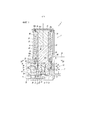
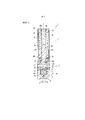
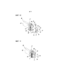
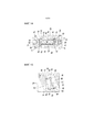
Фиг. 1 - вид сбоку в сечении электромагнитного клапана по варианту настоящего изобретения в размагниченном состоянии.FIG. 1 is a cross-sectional side view of an electromagnetic valve according to an embodiment of the present invention in a demagnetized state.
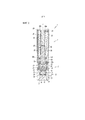
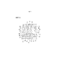
Фиг. 2 - вертикальное сечение электромагнитного клапана по фиг. 1.FIG. 2 is a vertical section of the electromagnetic valve of FIG. 1.
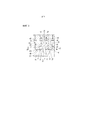
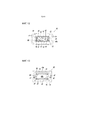
Фиг. 3 - схематическое сечение в увеличенном масштабе основной части, показывающее состояние вокруг камеры клапана по фиг. 1.FIG. 3 is an enlarged schematic sectional view of a main part showing the state around the valve chamber of FIG. 1.
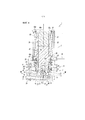
Фиг. 4 - вид сбоку в сечении электромагнитного клапана в возбужденном состоянии.FIG. 4 is a cross-sectional side view of an energized solenoid valve.
Фиг. 5 - Вертикальное сечение электромагнитного клапана по фиг. 4.FIG. 5 is a vertical section through the solenoid valve of FIG. 4.
Фиг. 6 - Схематическое сечение основной части, показывающее состояние вокруг камеры клапана на фиг. 4.FIG. 6 is a schematic cross-section of a main part showing the state around the valve chamber in FIG. 4.
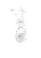
Фиг. 7 - разнесенный схематический вид в перспективе компонентов, относящихся к участку электромагнита по настоящему изобретению.FIG. 7 is an exploded schematic perspective view of components related to a portion of an electromagnet of the present invention.
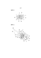
Фиг. 8 - сечение в увеличенном масштабе соответствующего участка по линии VIII-VIII на фиг. 4.FIG. 8 is an enlarged sectional view of a corresponding section along line VIII-VIII in FIG. 4.
Фиг. 9 - схематический вид в перспективе подвижного сердечника перед креплением элемента крышки к паре поддерживающих рычагов.FIG. 9 is a schematic perspective view of the movable core before attaching the lid member to a pair of support arms.
Фиг. 10 - схематический вид в перспективе состояния, когда направляющие канавки тарелки клапана вставлены между парой поддерживающих рычагов из состояния, показанного на фиг. 9.FIG. 10 is a schematic perspective view of a state where the guide grooves of the valve disc are inserted between a pair of support arms from the state shown in FIG. nine.
Фиг. 11 - схематический вид в перспективе состояния, когда элемент крышки растянут между парой поддерживающих рычагов из состояния, показанного на фиг. 10.FIG. 11 is a schematic perspective view of a state where the lid member is stretched between a pair of support arms from the state shown in FIG. ten.
Фиг. 12 - схематическое сечение состояния, когда подвижный сердечник вставлен в центральное отверстие бобины.FIG. 12 is a schematic sectional view of the state when the movable core is inserted into the center hole of the bobbin.
Фиг. 13 - схематический вид сверху отверстия бобины, расположенного ближе к корпусу клапана.FIG. 13 is a schematic top view of the reel opening closer to the valve body.
Фиг. 14 - сечение в увеличенном масштабе основной части по линии XIV-XIV на фиг. 1.FIG. 14 is an enlarged sectional view of the main part along the line XIV-XIV in FIG. 1.
Фиг. 15 - схематический вид в перспективе состояния, когда магнитное кольцо прикреплено к зацепляющему выступу бобины.FIG. 15 is a schematic perspective view of a state where a magnetic ring is attached to a bobbin engaging protrusion.
Описание вариантовDescription of options
[0018][0018]
На фиг. 1-15 показан электромагнитный клапан по варианту настоящего изобретения. Электромагнитный клапан 1 по настоящему изобретению в основном содержит участок 2 клапана, содержащий тарелку 3 клапана для переключения проточного канала, по которому течет текучая среда под давление, например, воздух, и участок 7 электромагнита, который приводит в движение тарелку 3 клапана в основном участке 2 клапана. Основной участок 2 клапана и участок 7 электромагнита соединены последовательно в направлении оси L электромагнитного клапана 1.FIG. 1-15 show a solenoid valve according to an embodiment of the present invention. The
[0019][0019]
Как понятно из фиг. 1 и 2, основной участок 2 клапана содержит корпус 10 клапана, имеющий прямоугольное сечение. На первой боковой поверхности корпуса 10 клапана сформированы впускное окно Р, выпускное окно А и выхлопное окно R. Внутри корпуса 10 клапана сформирована камера 11 клапана, с которой сообщаются впускное окно P, выпускное окно A и выхлопное окно R. К этим окнам прикреплена прокладка 29.As is clear from FIG. 1 and 2, the
[0020][0020]
Как показано на фиг. 1 и фиг. 4, в камере 11 клапана расположены первое седло 12 клапана и втрое седло 13 клапана, к которым и от которых движется тарелка 3 клапана. Первое седло 12 клапана и второе седло 13 клапана обращены друг к другу в направлении оси L. Первое седло 12 клапана находится на поверхности 14 нижней стенки камеры 11 клапана, окружая впускное сквозное отверстие 15, расположенное по существу в центральной части поверхности 14 нижней стенки и направленное в сторону участка 7 электромагнита. Впускное сквозное отверстие 15 сообщается с впускным коммуникационным каналом 16, сформированным ближе ко дну корпуса 10 клапана, чем поверхность 14 нижней стенки. Впускной коммуникационный канал 16 сообщается с впускным окном P. Таким образом, впускное окно P сообщается с камерой 11 клапана через впускное сковное отверстие 15.As shown in FIG. 1 and FIG. 4, a
[0021][0021]
С другой стороны, второе село 13 клапана расположено на держателе 17, прикрепленном к камере 11 клапана. Держатель 17 изготовлен из материала смолы и расположен в камере 11 клапана на участке, находящемся ближе к кромке открывания (ближе к участку 7 электромагнита) камеры 11 клапана, чем тарелка 3 клапана. Держатель 17 содержит круглый внешний периферийный участок 20, который вставлен во внутреннюю периферийную стенку камеры 11 клапана, и выступ 19, который расположен внутри внешнего периферийного участка 20 и выступает в направлении первого седла 12 клапана.On the other hand, the
[0022][0022]
Как показано на фиг. 1 и фиг. 2, на конце (вершине) выступа 19 держателя 17 сформировано выхлопное сквозное отверстие 21, которое сообщается с выхлопным окном R. Второе седло 13 клапана, имеющее кольцевую форму, расположено вокруг выхлопного сквозного отверстия 21. В кольцевом внешнем периферийном участке 20 сформирована кольцевая канавка 22. К обеим сторонам кольцевой канавки 22 в направлении оси L прикреплены уплотняющие элементы 23 для герметичного уплотнения камеры 11 клапана. Кольцевая канавка 22 сообщается с выхлопным коммуникационным каналом 24, сообщающимся с выхлопным сквозным отверстием 21. Таким образом, выхлопное окно R сообщается с внутренней полостью камеры 11 клапана через кольцевую канавку 22, выхлопной коммуникационный канал 24 и выхлопное сквозное отверстие 21. Между выступом 19 и кольцевым внешним периферийным участком 20 сформирована пара установочных отверстий 25, в которые вставлены пара поддерживающих рычагов 45 подвижного сердечника 40, описанные ниже (см. фиг. 1 и фиг. 9).As shown in FIG. 1 and FIG. 2, an exhaust through
[0023][0023]
Как показано на фиг. 1 и фиг. 4, тарелка 3 клапана, который является тарельчатым клапаном, расположена в камере 11 клапана в пространстве между первым седлом 12 клапана и вторым седлом 13 клапана. Тарелка 3 клапана сформирована из упругого материала смолы, обладающего уплотняющими свойствами, например, резины, и имеет по существу прямоугольную форму. Тарелка 3 клапана движется к первому седлу 12 клапана и второму седлу 13 клапан и от них для изменения состояний соединения между окнами P, A и R. Между тарелкой 3 клапана и держателем 17, прикрепленным к корпусу 10 клапана, установлен упругий элемент 26, образованный витой пружиной. Упругий элемент 26 постоянно поджимает тарелку 3 клапана к первому седлу 12 клапана. Когда участок 7 электромагнита находится в не возбужденном состоянии (размагниченном состоянии), тарелка 3 клапана сидит на первом седле 12 клапана за счет прижимающей силы упругого элемента 26 (см. фиг. 1-3). В настоящем варианте базовый конец выступа 19 держателя 17 функционирует как гнездо пружины для упругого элемента 26.As shown in FIG. 1 and FIG. 4, a
[0024][0024]
Как показано на фиг. 8, тарелка 3 клапана содержит пару направляющих канавок 3a, которые открыты в противоположных направлениях и расположены на концевых поверхностях тарелки 3 клапана в направлении ширины (направление лево-право на фиг. 8), проходя в направлении оси L. Когда в направляющие канавки 3a вставлена пара поддерживающих рычагов 45 подвижного сердечника 40, описанные ниже, тарелка 3 клапана поддерживается между этой парой поддерживающих рычагов 45 с возможностью скольжения в направлении оси L. Эта структура, содержащая направляющие канавки 3a, может предотвратить перемещение тарелки 3 клапана в направлении, перпендикулярном оси подвижного сердечника 40 и предотвратить перекос оси тарелки 3 клапана. Таким образом, тарелка 3 клапана можно прочно посадить на первое седло 12 и на второе седло 13 клапана.As shown in FIG. 8, the
[0025][0025]
Далее следует описание участка 7 электромагнита. Как показано на фиг. 1 и фиг. 7, участок 7 электромагнита содержит магнитный кожух 30 прямоугольного сечения с первым концом (верхний конец на фиг. 1) в направлении оси L, закрытым крышкой 31. Как показано на фиг. 1, внутри магнитного кожуха 30 расположены бобина 60, на которую намотана обмотка 32, неподвижный сердечник 35, прикрепленный к центральному отверстию 60a бобины 60, подвижный сердечник 40, вставленный в центральное отверстие 60a с возможностью скольжения в направлении оси L, и магнитное кольцо 80, расположенное на конце бобины 60 рядом с корпусом 10 клапана и окружающее вход в центральное отверстие 60a. Как показано на фиг. 1 и фиг. 4, между крышкой 31 и бобиной 60 и между бобиной 60 и магнитным кольцом 80 сформированы кольцевые канавки 60b. В соответствующих канавках 60b установлены уплотняющие элементы 38. Пара клемм 39 обмотки, электрически соединенные с обмоткой 32 возбуждения, выступает из боковой поверхности магнитного кожуха 30. К клеммам 39 подключены провода.The following is a description of the
[0026][0026]
Неподвижный сердечник 35 изготовлен из металлического материала и имеет форму по существу прямоугольной пластины. Неподвижный сердечник 35 содержит участок 35a фланца на первом конце (на верхнем конце на фиг. 1) в направлении оси L. Неподвижный сердечник 35 удерживается между бобиной 60 и крышкой 31, а его участок 35a фланца находится в зацеплении с концевой частью бобины 60, расположенной ближе к крышке 31.The fixed
[0027][0027]
С другой стороны, подвижный сердечник 40 смещается в направлении оси L при возбуждении и размагничивании участка 7 электромагнита и движение подвижного сердечника 40 в направлении оси L сажает тарелку 3 клапана на первое седло 12 и на второе седло 13 клапана. Более конкретно, когда на обмотку 32 подается питание (состояние возбуждения), как показано на фиг. 4-6, подвижный сердечник 40 притягивается к неподвижному сердечнику 35, поэтому тарелка 3 клапана сходит с первого седла 12 клапана и садится на второе седло 13 клапана и впускное окно P и выпускное окно A сообщаются друг с другом через камеру 11 клапана.On the other hand, the
Наоборот, когда питание на обмотку 32 возбуждения не подается (размагниченное состояние), как показано на фиг. 1-3, подвижный сердечник 40 отходит от неподвижного сердечника 35 и тарелка 3 клапана сходит со второго седла 13 клапана и садится на первое седло 12 клапана, и выпускное окно A и выхлопное окно R сообщаются друг с другом через камеру 11 клапана.Conversely, when power is not supplied to the field winding 32 (demagnetized state), as shown in FIG. 1-3, the
[0028][0028]
Подвижный сердечник 40 имеет первый конец, в направлении оси L, и второй конец в направлении оси L. Железный сердечник 43 имеющий форму пластины по существу прямоугольного сечения, расположен на первом конце. Участки поддержки клапана (поддерживающие рычаги 45), которые выступают в направлении оси L за торцевую поверхность 43a железного сердечника 43, расположены на стороне второго конца. Железный сердечник 43 обращен к неподвижному сердечнику 35 и притягивается к неподвижному сердечнику 35 или отходит от него в ответ на наличие или отсутствие питания на обмотке 32 возбуждения.The
[0029][0029]
Как показано на фиг. 1 и фиг. 4, участок поддержки клапана содержит пару поддерживающих рычагов 45, которые бесшовно интегрированы с железным сердечником 43. Эти поддерживающие рычаги 45 расположены бок о бок на обоих концах подвижного сердечника 40 в направлении ширины (в направлении лево-право на фиг. 1) и являются двустороннесимметричными относительно оси L. Подвижный сердечник 40 изготовлен из единой пластины из магнитного металла. Из этой металлической пластины путем штампования получен железный сердечник 43 и участок поддержки клапана (т.е. поддерживающие рычаги 45), сформированные интегрально. Таким образом, как показано на фиг. 2 и фиг. 9-11, пара поверхностей (боковых поверхностей) 50, параллельных друг другу на обеих сторонах в направлении толщины подвижного сердечника 40 (в направлении лево-право на фиг. 2) являются едиными плоскими поверхностями, непрерывно проходящими от железного сердечника 43 для поддерживающих рычагов 45.As shown in FIG. 1 and FIG. 4, the flap support portion comprises a pair of
[0030][0030]
Как показано на фиг. 1 и фиг. 4, пара поддерживающих рычагов 45 входит в камеру 11 в корпусе 10 клапана через пару установочных отверстий 25, открытых в держателе 17 и, внутри камеры 11 клапана, вставлены в пару направляющих канавок 3a (см. фиг 8), сформированных в тарелке 8 клапана с возможностью смещаться в направлении оси L относительно тарелки 3 клапана. Таким образом, тарелка 3 клапана поддерживается между парой поддерживающих рычагов 45 с возможностью скольжения в направлении оси L.As shown in FIG. 1 and FIG. 4, a pair of
Вместо фиксации на подвижном сердечнике 40, тарелка 3 клапана подвижно поддерживается подвижным сердечником 40 так, что участок поддержки клапана подвижного сердечника 40 можно конструировать более свободно и получать более простую структуру или форму.Instead of being fixed to the
[0031][0031]
Как показано на фиг. 3 и фиг. 6, пара поддерживающих рычагов 45 соответственно содержит на участках своих дальних концов зацепляющие крюки 47, выступающие в направлении друг от друга. Каждый из зацепляющих крюков 47 имеет наклонную поверхность 47a. Наклонная поверхность 47a постепенно наклоняется к оси L по мере приближения к поверхности 46 дальнего конца соответствующего поддерживающего рычага 45. Каждый из зацепляющих крюков 47 имеет зацепляющую поверхность 47b, сформированную из концевой поверхности, перпендикулярной оси L на участке основания.As shown in FIG. 3 and FIG. 6, the pair of
[0032][0032]
Как показано на фиг. 3, фиг. 6 и фиг. 9, элемент 70 колпачка растянут между участками дальних концов пары поддерживающих рычагов 45. Элемент 70 колпачка сформирован из упругой металлической тонкой пластины по существу U-образного сечения. Элемент 70 колпачка имеет пару зацепляющих отверстий 71, находящихся в зацеплении с зацепляющими крюками 47, и клапанное отверстие 72, расположенное между парой зацепляющих отверстия 71. Тарелка 3 клапана садится на первое седло 12 клапана сквозь клапанное отверстие 72.As shown in FIG. 3, fig. 6 and FIG. 9, the
[0033][0033]
Как показано на фиг. 9, элемент 70 колпачка содержит тонкий пластинчатый участок 73 зацепления с клапаном, проходящий в направлении, перпендикулярном оси L и обладающий упругостью в направлении оси L, и пару запирающих участков 74, отходящих от левого и правого концов участка зацепления с клапаном в по существу перпендикулярном направлении. Соединительные участки между участком 73 зацепления с клапаном и запирающими участками 74 плавно изогнуты и имеют дугообразную форму. Когда подвижный сердечник 40 притягивается к неподвижному сердечнику 35, участок 73 зацепления с клапаном входит в зацепление с участком 4 зацепления (торцевой поверхностью, обращенной к первому седлу 12 клапана) тарелки 3 клапана, сидящего на первом седле клапана 12, как показано на фиг. 6. Поэтому тарелка 3 клапана отходит от первого седла 13 клапана, преодолевая прижимающее действие упругого элемента 26, и садится на второе седло 13 клапана. Участок 73 зацепления с клапаном имеет клапанное отверстие 72. Как показано на фиг. 3, тарелка 3 клапана может садиться на первое седло 12 клапана через отверстие 72.As shown in FIG. 9, the
[0034][0034]
Как показано на фиг. 9, зацепляющие отверстия 71 являются прямоугольными и сформированы в участках, расположенных поперек участка 73 зацепления с клапаном и запирающих участков 74. На дальних концах запирающих участков 74 сформированы изогнутые участки 75, отогнутые наружу. Как описано выше, элемент 70 колпачка изготовлен из тонкой металлический пластины и имеет простую конструкцию, что позволяет крепить тарелку 3 клапана к участку поддержки клапана (поддерживающим рычагам 45) подвижного сердечника 40 и формировать участок 73 зацепления с клапаном.As shown in FIG. 9, the engaging
[0035][0035]
Элемент 70 колпачка крепится между поддерживающими рычагами 45 следующим образом. Во-первых, как показано на фиг. 9, подготавливают подвижный сердечник 40, держатель 17, упругий элемент 26, тарелку 3 клапана и элемент 70 колпачка. Упругий элемент 26, сформированный из витой пружины, крепят к внешней периферии выступа 19 держателя 17. Затем оси подвижного сердечника 40 и держателя 17, к которому прикреплен упругий элемент 26, выравнивают друг с другом и пару поддерживающих рычагов 45 вставляют установочные отверстия 25 держателя 17 с одной стороны держателя 17 в направлении оси L (со стороны, противоположной выступу 19). Таким образом, в направляющие канавки 3a тарелки 3 клапана входит пара поддерживающих рычагов 45, проходящих сквозь установочные отверстия 25 (см. фиг. 10). В этом состоянии, элемент 70 колпачка крепят между поддерживающими рычагами 45.The
[0036][0036]
Как показано на фиг. 10, когда элемент 70 колпачка выталкивается относительно поддерживающих рычагов 45, а сторона открывания (сторона запирающих участков 74) элемента 70 колпачка обращена к поверхностям 46 дальнего конца поддерживающих рычагов 45, изогнутые участки 75 пары запирающих участков 74 элемента 70 колпачка скользят по наклонным поверхностям 47a зацепляющих крюков 47 на участках дальнего конца поддерживающих рычагов 45. Таким образом, расстояние между запирающими участками 74 упруго увеличивается. Затем, открывающие кромки (свободные концы) зацепляющих отверстий 71 запирающих участков 74 смещаются к зацепляющим поверхностям 47b зацепляющих крюков 47 и положения зацепляющих отверстий 71 и положения зацепляющих крюков 47 выравниваются друг с другом. Таким образом, увеличенные запирающие участки 74 упруго восстанавливаются и зацепляющие крюки 74 входят в зацепляющие отверстия 71, как показано на фиг. 11. На этом завершается процесс установки элемента 70 колпачка на поддерживающие рычаги 45.As shown in FIG. 10, when the
[0037][0037]
Как показано на фиг. 3, фиг. 4 и фиг. 6, поверхности 46 дальнего конца пары поддерживающих рычагов 45 являются плоскими поверхностями, перпендикулярными оси L. С другой стороны, на поверхности 14 нижней стенки камеры 11 клапана, обращенной к поверхностям 46 дальнего конца, имеется пара контактных поверхностей 27, к которым и от которых движутся поверхности 46 дальнего конца. Эта пара контактных поверхностей 27 является плоскими поверхностями, параллельными поверхностям 46 дальнего конца поддерживающих рычагов 45. Контактные поверхности 27 расположены по обе стороны от первого седла 12 клапана на поверхности 14 нижней стенки, т.е. на обеих сторонах корпуса 10 клапана в направлении ширины (направление лево-право на фиг. 3), и выступают в направлении участка 7 электромагнита. Высота контактных поверхностей 27, на которую они выступают над поверхностью 14 нижней стенки в камеру 11 клапана, меньше, чем высота, на которую первое седло 12 клапана вступает из поверхности 14 нижней стенки в камеру 11 клапана. Более конкретно, контактные поверхности 27 расположены ближе к поверхности 14 нижней стенки, чем первое седло 12 клапана.As shown in FIG. 3, fig. 4 and FIG. 6, the distal end surfaces 46 of the pair of
[0038][0038]
В настоящем варианте, как показано на фиг. 1 и фиг. 3, когда подвижный сердечник 40 сдвигается ко второму концу (к первому седлу 12 клапана) и тарелка 3 клапана садится на первое седло 12 клапана, поверхности 46 дальнего конца пары поддерживающих рычагов 45 упираются в контактные поверхности 27. В это время, как показано на фиг. 3, участок 73 зацепления с клапаном элемента 70 колпачка не контактирует с зацепленным участком 4 тарелки 3 клапана, и между участком 73 зацепления с клапаном и зацепленным участком 4 формируется зазор G, величина которого меньше, чем ход подвижного сердечника 40.In the present embodiment, as shown in FIG. 1 and FIG. 3, when the
[0039][0039]
Как показано на фиг. 12, центральное отверстие 60a бобины 60, в котором расположен подвижный сердечник 40, имеет по существу прямоугольное сечение с парой первых внутренних поверхностей 61 и парой вторых внутренних поверхностей 65. Первые внутренние поверхности 61 обращены к паре поверхностей 50 на обеих сторонах подвижного сердечника 40 в направлении толщины, а вторые внутренние поверхности 65 обращены к паре боковых концевых поверхностей 51 параллельных друг другу и расположенных на обоих концах подвижного сердечника 40 (железного сердечника 43) в направлении ширины (в направлении лево-право на фиг. 12).As shown in FIG. 12, the
[0040][0040]
На обоих боковых участках 62 пары первых внутренних поверхностей 61 в направлении ширины сформированы ступенчатые участки 64 для уменьшения расстояние между первыми внутренними поверхностями так, чтобы оно было меньше, чем расстояние между промежуточными участками 63, расположенными между обоими боковыми участками 62. Ступенчатые участки 64 проходят в направлении оси L и соединены со вторыми внутренними поверхностями 65 с обоих боковых участков 62 первых внутренних поверхностей 61 в периферийном направлении центрального отверстия 60a. На паре вторых внутренних поверхностей 65 сформирована пара выпуклых выступов 66, проходящих в направлении оси L. Выпуклые выступы 66 сформированы на вторых внутренних поверхностях 65 так, чтобы они были обращены друг к другу (обращены внутрь) и имели дугообразное сечение.On both
[0041][0041]
Когда железный сердечник 43 подвижного сердечника 40 вставлен в центральное отверстие 60a бобины 60, пара боковых концевых поверхностей 51 поддерживается парой выпуклых выступов 66 с возможностью скольжения в направлении оси L, а пара поверхностей 50 поддерживается ступенчатыми участками 64 с возможностью скольжения в направлении оси L. Подвижный сердечник проходит сквозь магнитное кольцо 80 так, чтобы его дальний конец выступал в направлении корпуса 10 клапана.When the
В настоящем варианте обе боковые концевые поверхности 51 подвижного сердечника 40 и оба боковых участка пары поверхностей 50 поддерживаются выпуклыми выступами 66 м ступенчатыми участками 64 с возможностью скольжения в центральном отверстии 60a бобины 60. Поэтому, эффективно предотвращается перекос оси подвижного сердечника 40.In the present embodiment, both side end surfaces 51 of the
[0042][0042]
Как показано на фиг. 7 и фиг. 13-15, на входе центрального отверстия 60a расположена пара зацепляющих выступающих стенок 76, обращенных к корпусу 10 клапана. Эти зацепляющие выступающие стенки 67 отходят от пары вторых внутренних поверхностей 65 в направлении оси L. Магнитное кольцо 80, окружающее центральное отверстие 80a имеет участок 81 зацепляющего отверстия. Когда зацепляющие выступающие стенки 67 вставлены в участок 81 зацепляющего отверстия, магнитное кольцо 80 позиционируется соосно с бобиной 60.As shown in FIG. 7 and FIG. 13-15, at the entrance of the
[0043][0043]
Как показано на фиг. 7 и фиг. 13-15, каждая из зацепляющих выступающих стенок 67 бобины 60 содержит участок 68 боковой стенки, обращенные к обеим боковым концевым поверхностям 51 подвижного сердечника 40, и полукруглые дугообразные участки 69 стенки на обеих сторонах (верхняя и нижняя стороны на фиг. 13) участка 68 боковой стенки. С другой стороны, как показано на фиг. 7, фиг. 14 и фиг. 15, участок 81 зацепляющего отверстия магнитного кольца 80 имеет пару участков 82 первых поверхностей, проходящих параллельно друг другу и обращенных к паре поверхностей 50 подвижного сердечника, и участки 83 вторых поверхностей на обеих сторонах участков 82 первых поверхностей. Расстояние между участками 82 первых поверхностей больше, чем толщина подвижного сердечника 40 (расстояние между парой поверхностей 50), и расстояние между промежуточными участками 63 первых внутренних поверхностей 61 центрального отверстия 60a.As shown in FIG. 7 and FIG. 13-15, each of the engaging protruding
Каждый участок 83 второй поверхности содержит прямой участок 84, с которым зацеплен зацепляющая выступающая стенка 67 и который проходит в направлении, перпендикулярном участку 82 первой поверхности, и полукруглые дугообразные участки 85 по обе стороны от прямого участка 84. Прямой участок 84 находится в зацеплении с внешней периферийной поверхностью участка 68 боковой стенки соответствующей зацепляющей выступающей стенки 67. Дугообразные участки 85 находятся в зацеплении с внешними периферийными поверхностями дугообразных концевых участков 69 зацепляющей выступающей стенки 67.Each
[0044][0044]
Как показано на фиг. 14, магнитное кольцо 80 имеет внешнюю периферийную поверхность, по существу прямоугольную в плане, и пару углублений 86 в обеих боковых поверхностях внешней периферийной поверхности в направлении ширины. Пара углублений 86 находится в зацеплении с парой направленных внутрь выступов 28, расположенных в камере 11 клапана корпуса 10 клапана.As shown in FIG. 14, the
Как описано выше, когда магнитное кольцо 80 прикреплено к входу центрального отверстия 60a, как показано на фиг. 14, зацепляющие выступающие стенки 67 бобины 60 и участок 81 зацепляющего отверстия магнитного кольца 80 находятся в зацеплении друг с другом, и углубления 86 и направленные внутрь выступы 28 находятся в зацеплении друг с другом. Поэтому оси магнитного кольца 80 и центрального отверстия 60a совпадают. Когда магнитное кольцо прикреплено к входу бобины 60, зацепляющие выступающие стенки 67 находятся между обеими боковыми концевыми поверхностями 51 подвижного сердечника и участками 83 вторых поверхностей магнитного кольца 80. В этом состоянии между каждым из участков 82 первых поверхностей магнитного кольца 80 и соответствующей поверхностью 50 подвижного сердечника 40 образуется зазор. Такая структура препятствует непосредственному контакту подвижного сердечника 40 и магнитного кольца 80 друг с другом. Поэтому эффективно предотвращается понижение эффективности участка 7 электромагнита.As described above, when the
[0045][0045]
В электромагнитном клапане 1, имеющем вышеописанную структуру, когда на обмотку 32 возбуждения питание не подается (размагниченное состояние), как показано на фиг. 1 и 2, подвижный сердечник 40 находится на расстоянии от неподвижного сердечника 35. Когда обмотка 32 возбуждения находится в размагниченном состоянии, тарелка 3 клапана посажена на первое седло 12 клапана под прижимающей силой упругого элемента 26, приложенной к ней через держатель 17, чтоб заблокировать сообщение между впускным окном P и камерой 11 клапана. В это время второе седло 13 клапана, обращенное к первому седлу 12 клапана в направлении оси L открыто, и выпускное окно A сообщается с выхлопным окном R через выхлопное сквозное отверстие 21 и выхлопной коммуникационный канал 24 в камере 11 клапана. Потому, текучая среда под давлением из камеры 11 клапана выпускается в атмосферу через выхлопное окно R, соединенное с атмосферой.In the
[0046][0046]
В этом варианте пока обмотка 32 возбуждения находится в размагниченном состоянии, как показано на фиг. 3, поверхности 46 дальнего конца поддерживающих рычагов 45 подвижного сердечника 40 упираются в пару контактных поверхностей 27 поверхности 14 нижней стенки камеры 11 клапана. Тарелка 3 клапана посажена на первое седло 12 клапана в отверстии 72 элемента 70 колпачка между парой поддерживающих рычагов 45. В это время торцевая поверхность (участок 4 зацепления) тарелки 3 клапана, обращенная к первому седлу 12 клапана, и участок 73 зацепления с капаном элемента 70 колпачка не контактируют друг с другом, и между зацепленным участком 4 и участком 73 зацепления с клапаном возникает зазор G, меньший, чем ход подвижного сердечника 40.In this embodiment, while the field winding 32 is in a demagnetized state as shown in FIG. 3, the distal end surfaces 46 of the
[0047][0047]
Когда в этом состоянии на обмотку 32 возбуждения подается питание, чтобы перевести ее в возбужденное состояние, подвижный сердечник 40 притягивается к неподвижному сердечнику 35 и смещается к неподвижному сердечнику 35 в направлении оси L, противодействуя прижимающей силе упругого элемента 26, который прижимает тарелку 3 клапана к первому седлу 12 клапана, как показано на фиг. 4-6. Как показано на фиг. 6, при смещении подвижного сердечника 40 в направлении оси L, пара поддерживающих рычагов 45 подвижного сердечника 40 отходят от контактных поверхностей 27, и участок 73 зацепления с клапаном элемента 70 колпачка, прикрепленный между поддерживающими рычагами 45, входит в зацепление с поверхностью 4 зацепления тарелки 3 клапана. Тарелка 3 клапана, сидящая на первом седле 12 клапана, смещается в направлении второго седла 13 клапана, поддерживаемая поддерживающими рычагами 45 через свои направляющие канавки 3a.When, in this state, the field winding 32 is energized to bring it to the energized state, the
[0045][0045]
Как описано выше, между участком 4 зацепления тарелки 3 клапана и участком 73 зацепления с клапаном элемента 70 колпачка возникает зазор G. Поэтому, когда обмотка 32 возбуждения переключается в возбужденное состояние, тарелка 3 клапана не сдвигается ко второму седлу 13 клапана одновременно с перемещением подвижного сердечника 40, а сначала сжимается зазор G между участком 4 зацепления и участком 73 зацепления с клапаном, и после того, как зазор G уменьшится до нуля, участок зацепления с клапаном, входит в зацепление с участком 4 зацепления тарелки 3 клапана и, после этого, тарелка 3 клапана смещается ко второму седлу 13 клапана.As described above, a gap G exists between the
[0049][0049]
Когда подвижный сердечник 40 притянут, тарелка 3 садится на второе седло 13 клапана, чтобы закрыть выхлопное отверстие 21 и открыть первое седло 12 клапана, обращенное ко второму седлу 13 клапана. Вследствие этого, впускное окно P сообщается с выпускным окном A через впускное сквозное отверстие 15 и камеру 11 клапана, и текучая среда под давлением, подаваемая через впускное окно P, выводится через выпускное окно A (см. фиг. 4-6). Здесь участок 73 зацепления с клапаном элемента 70 колпачка, расположенный на паре поддерживающих рычагов 45, сформирован из тонкой пластины, упругой в направлении оси L. Когда тарелка клапана посажена на второе седло 13 клапана, сила, прилагаемая к тарелке 3 клапана в направлении оси L, может поглощаться участком 73 зацепления с клапаном. Такая структура может предотвратить износ тарелки 3 клапана или ее необратимую деформацию (постоянную деформацию) в результате многократного приложения такой силы к тарелке 3 клапана.When the
[0050][0050]
Когда прекращается подача питания на обмотку 32 возбуждения, чтобы она переключилась в состояние размагничивания, показанное на фиг. 1 и фиг. 3, подвижный сердечник 40 отходит от неподвижного сердечника 35, и тарелка 3 клапана отходит от второго седла 13 клапана под действием прижимающей силы упругого элемента 26. Как было описано выше, тарелка 3 клапана закрывает первое седло 12 клапана и открывает второе седло 13 клапана, поэтому выпускное окно A сообщается с выхлопным окном R через камеру 11 клапан, и открывается в атмосферу. В это время плоские поверхности 46 дальнего конца пары поддерживающих рычагов 45 упираются в пару контактных поверхностей 27, которые расположены параллельно поверхностям 46 дальнего конца, поэтому подвижный сердечник 40 точно позиционируется относительно корпуса 10 клапана. Таким образом, отзывчивостью электромагнитного клапана можно управлять с большей точностью.When the power supply to the field winding 32 is stopped so that it switches to the demagnetization state shown in FIG. 1 and FIG. 3, the
[0051][0051]
Когда поверхности 46 дальних концов поддерживающих рычагов 45 упираются в контактные поверхности 27, тарелка 3 клапана садится на первое седло 12 клапана, и между участком 4 зацепления, обращенным к первому седлу 12 клапана и участком 73 зацепления с клапаном элемента 70 колпачка возникает зазор G. Такая структура может предотвратить непосредственное воздействие кинетической энергии подвижного сердечника 40 на тарелку 3 клапана, когда тарелка 3 клапана посажена на первое седло 12 клапана и, таким образом может уменьшить внешнюю силу, действующую на седло 3 клапана в направлении оси L. Поэтому можно предотвратить износ или необратимую деформацию (постоянную деформацию) тарелки 3 клапана в результате многократного приложения такой внешней силы к тарелке 3 клапана в направлении оси L так, что предотвращается изменение размеров тарелки 3 клапана со временем. Следовательно, можно предотвратить изменение хода подвижного сердечника 40, то есть, величины расстояние от первого седла 12 клапана до тарелки 3 клапана. Поэтому можно в максимальной степени предотвратить изменение расхода текучей среды, текучей через первое седло 12 клапана или отзывчивости электромагнитного клапана.When the distal end surfaces 46 of the
[0052][0052]
Как было описано выше, электромагнитный клапан 1 по настоящему изобретению позволяет сократить количество компонентов и упростить структуру или форму подвижного сердечника 40, путем бесшовного интегрирования железного сердечника 43 и участка поддержки клапана подвижного сердечника 40 друг с другом. Такая структура позволяет снизить производственные расходыAs described above, the
[0053][0053]
Выше был описан электромагнитный клапан по настоящему изобретению. Однако настоящее изобретение не ограничивается вышеописанным вариантом, и в его конструкцию, естественно, могут быть внесены различные изменения, которые входят в объем защиты, определенный формулой изобретения.The electromagnetic valve of the present invention has been described above. However, the present invention is not limited to the above-described embodiment, and various changes can naturally be made to its construction, which fall within the scope of protection defined by the claims.
Например, хотя в вышеприведенном примере был описан трехпутевой распределитель, количество окон не ограничивается и может быть равно двум.For example, although a three-way distributor has been described in the above example, the number of windows is not limited and may be two.
Перечень позицийList of positions
[0054][0054]
1 - электромагнитный клапан1 - solenoid valve
3 - тарелка клапана3 - valve plate
3a - направляющая канавка3a - guide groove
4 - участок зацепления4 - area of engagement
7 - участок электромагнита7 - section of the electromagnet
10 - корпус клапана10 - valve body
11 - камера клапана11 - valve chamber
12 - первое седло клапана12 - the first valve seat
13 - второе седло клапана13 - the second valve seat
14 - поверхность нижней стенки14 - bottom wall surface
26 - упругий элемент26 - elastic element
27 - контактная поверхность27 - contact surface
40 - подвижный сердечник40 - movable core
43 - железный сердечник43 - iron core
43a - торцевая поверхность43a - end face
45 - поддерживающий рычаг (участок поддержки клапана)45 - support arm (valve support area)
47 - зацепляющий крюк47 - hook hook
50 - поверхность50 - surface
51 - боковая концевая поверхность51 - lateral end surface
60 - бобина60 - reel
60a - центральное отверстие60a - center hole
61 - первая внутренняя поверхность61 - first inner surface
62 - боковой участок62 - side section
63 - промежуточный участок63 - intermediate section
64 - ступенчатый участок64 - stepped section
65 - вторая внутренняя поверхность65 - second inner surface
66 - выпуклый выступ66 - convex ledge
67 - зацепляющаяся выступающая стенка67 - engaging protruding wall
70 - элемент колпачка70 - cap element
71 - зацепляющее отверстие71 - engaging hole
72 - клапанное отверстие72 - valve hole
73 - участок зацепления с клапаном73 - section of engagement with the valve
80 - магнитное кольцо80 - magnetic ring
81 - участок зацепляющего отверстия81 - section of the engaging hole
A - выпускное отверстиеA - outlet
P - впускное отверстиеP - inlet
R - выпускное отверстие.R is the outlet.
Claims (43)
Applications Claiming Priority (3)
| Application Number | Priority Date | Filing Date | Title |
|---|---|---|---|
| JP2016-100913 | 2016-05-19 | ||
| JP2016100913A JP6698251B2 (en) | 2016-05-19 | 2016-05-19 | solenoid valve |
| PCT/JP2017/017637 WO2017199803A1 (en) | 2016-05-19 | 2017-05-10 | Solenoid valve |
Publications (3)
| Publication Number | Publication Date |
|---|---|
| RU2018144577A RU2018144577A (en) | 2020-06-19 |
| RU2018144577A3 RU2018144577A3 (en) | 2020-06-19 |
| RU2728545C2 true RU2728545C2 (en) | 2020-07-30 |
Family
ID=60325829
Family Applications (1)
| Application Number | Title | Priority Date | Filing Date |
|---|---|---|---|
| RU2018144577A RU2728545C2 (en) | 2016-05-19 | 2017-05-10 | Solenoid valve |
Country Status (10)
| Country | Link |
|---|---|
| US (1) | US10746316B2 (en) |
| JP (1) | JP6698251B2 (en) |
| KR (1) | KR102241234B1 (en) |
| CN (1) | CN109196260B (en) |
| BR (1) | BR112018072354A2 (en) |
| DE (1) | DE112017002526T5 (en) |
| MX (1) | MX2018014200A (en) |
| RU (1) | RU2728545C2 (en) |
| TW (1) | TWI729123B (en) |
| WO (1) | WO2017199803A1 (en) |
Families Citing this family (4)
| Publication number | Priority date | Publication date | Assignee | Title |
|---|---|---|---|---|
| CN108825856A (en) * | 2018-07-17 | 2018-11-16 | 宁波飞泰工业自控设备有限公司 | A kind of electromagnetic valve coil |
| JP7089242B2 (en) | 2018-09-21 | 2022-06-22 | Smc株式会社 | solenoid valve |
| JP7041414B2 (en) * | 2018-10-31 | 2022-03-24 | Smc株式会社 | solenoid valve |
| KR102490675B1 (en) * | 2021-06-08 | 2023-01-26 | 주식회사 유니크 | Solenoid valve |
Citations (5)
| Publication number | Priority date | Publication date | Assignee | Title |
|---|---|---|---|---|
| JP2000199411A (en) * | 1998-11-04 | 2000-07-18 | Mikuni Corp | Valve drive device |
| JP2003172470A (en) * | 2001-12-04 | 2003-06-20 | Smc Corp | Solenoid valve |
| RU98517U1 (en) * | 2010-05-27 | 2010-10-20 | Общество с ограниченной ответственностью Научно-производственное предприятие "Технопроект" | SOLENOID VALVE |
| RU2477408C2 (en) * | 2010-10-13 | 2013-03-10 | Закрытое акционерное общество Производственная компания "Промконтроллер" | Electromagnetic shutoff valve |
| JP2013142470A (en) * | 2012-01-13 | 2013-07-22 | Toto Ltd | Solenoid valve |
Family Cites Families (16)
| Publication number | Priority date | Publication date | Assignee | Title |
|---|---|---|---|---|
| US5192936A (en) * | 1991-08-22 | 1993-03-09 | Mac Valves, Inc. | Solenoid |
| WO2001061226A1 (en) * | 2000-02-18 | 2001-08-23 | Asco Controls, L.P. | Extended range proportional valve |
| JP4247314B2 (en) * | 2000-12-25 | 2009-04-02 | Smc株式会社 | Solenoid for solenoid valve |
| DE60208965T2 (en) * | 2001-12-04 | 2006-08-17 | Smc K.K. | Electromagnetic valve |
| JP3833525B2 (en) | 2001-12-04 | 2006-10-11 | Smc株式会社 | solenoid valve |
| JP4482762B2 (en) * | 2005-05-26 | 2010-06-16 | Smc株式会社 | Poppet type 2-port solenoid valve |
| JP2008157352A (en) * | 2006-12-22 | 2008-07-10 | Smc Corp | Solenoid valve |
| KR200440725Y1 (en) | 2007-02-06 | 2008-06-27 | 신영제어기 주식회사 | Poppet-type direct-acting solenoid-operated valve having buffer unit |
| JP4465537B2 (en) * | 2007-06-14 | 2010-05-19 | Smc株式会社 | solenoid valve |
| JP4453044B2 (en) * | 2007-06-18 | 2010-04-21 | Smc株式会社 | solenoid valve |
| JP4362853B2 (en) * | 2007-06-18 | 2009-11-11 | Smc株式会社 | 2-port solenoid valve |
| JP2011133071A (en) * | 2009-12-25 | 2011-07-07 | Ckd Corp | Self-holding solenoid valve |
| JP5486987B2 (en) * | 2010-03-31 | 2014-05-07 | Ckd株式会社 | Balance poppet type solenoid valve |
| CN102330834B (en) * | 2011-09-07 | 2014-08-20 | 浙江中宝自控元件有限公司 | Electromagnetic valve |
| US8783653B2 (en) * | 2012-12-21 | 2014-07-22 | Mac Valves, Inc. | Multi-port modular valve with snap-in seat |
| JP5938378B2 (en) * | 2013-09-18 | 2016-06-22 | Ckd株式会社 | solenoid valve |
-
2016
- 2016-05-19 JP JP2016100913A patent/JP6698251B2/en active Active
-
2017
- 2017-05-03 TW TW106114675A patent/TWI729123B/en active
- 2017-05-10 BR BR112018072354-1A patent/BR112018072354A2/en not_active IP Right Cessation
- 2017-05-10 US US16/301,796 patent/US10746316B2/en active Active
- 2017-05-10 MX MX2018014200A patent/MX2018014200A/en unknown
- 2017-05-10 WO PCT/JP2017/017637 patent/WO2017199803A1/en active Application Filing
- 2017-05-10 RU RU2018144577A patent/RU2728545C2/en active
- 2017-05-10 KR KR1020187033533A patent/KR102241234B1/en active IP Right Grant
- 2017-05-10 CN CN201780030284.0A patent/CN109196260B/en active Active
- 2017-05-10 DE DE112017002526.5T patent/DE112017002526T5/en active Pending
Patent Citations (5)
| Publication number | Priority date | Publication date | Assignee | Title |
|---|---|---|---|---|
| JP2000199411A (en) * | 1998-11-04 | 2000-07-18 | Mikuni Corp | Valve drive device |
| JP2003172470A (en) * | 2001-12-04 | 2003-06-20 | Smc Corp | Solenoid valve |
| RU98517U1 (en) * | 2010-05-27 | 2010-10-20 | Общество с ограниченной ответственностью Научно-производственное предприятие "Технопроект" | SOLENOID VALVE |
| RU2477408C2 (en) * | 2010-10-13 | 2013-03-10 | Закрытое акционерное общество Производственная компания "Промконтроллер" | Electromagnetic shutoff valve |
| JP2013142470A (en) * | 2012-01-13 | 2013-07-22 | Toto Ltd | Solenoid valve |
Also Published As
| Publication number | Publication date |
|---|---|
| JP6698251B2 (en) | 2020-05-27 |
| BR112018072354A2 (en) | 2019-02-19 |
| WO2017199803A1 (en) | 2017-11-23 |
| RU2018144577A (en) | 2020-06-19 |
| KR102241234B1 (en) | 2021-04-16 |
| CN109196260A (en) | 2019-01-11 |
| US10746316B2 (en) | 2020-08-18 |
| MX2018014200A (en) | 2019-02-25 |
| TW201812199A (en) | 2018-04-01 |
| CN109196260B (en) | 2020-04-03 |
| DE112017002526T5 (en) | 2019-03-21 |
| KR20190007432A (en) | 2019-01-22 |
| RU2018144577A3 (en) | 2020-06-19 |
| JP2017207158A (en) | 2017-11-24 |
| TWI729123B (en) | 2021-06-01 |
| US20190154166A1 (en) | 2019-05-23 |
Similar Documents
| Publication | Publication Date | Title |
|---|---|---|
| RU2728545C2 (en) | Solenoid valve | |
| US7523763B2 (en) | Three-port electromagnetic valve | |
| EP1318340B1 (en) | Solenoid-operated valve | |
| JP5854386B2 (en) | High frequency switching valve | |
| US7520488B2 (en) | Poppet-type two-port solenoid valve | |
| RU2733142C2 (en) | Solenoid valve | |
| JP2012184844A (en) | Solenoid valve | |
| JP2017207158A5 (en) | ||
| CN111102395A (en) | Solenoid valve and method for operating a solenoid valve | |
| US20190383415A1 (en) | Electromagnetic Valve | |
| CN218326365U (en) | High-speed electromagnetic switch valve | |
| JP3863768B2 (en) | solenoid valve | |
| CN213451989U (en) | Electromagnetic valve | |
| CN219493066U (en) | Solenoid valve and have its automobile body posture control device and car | |
| JPH0328221Y2 (en) | ||
| RU44364U1 (en) | ELECTROMAGNETIC VALVE OF INDIRECT ACTION | |
| CN115614505A (en) | High-speed electromagnetic valve | |
| CN114484016A (en) | Two-position four-way electromagnetic valve | |
| KR20130142649A (en) | Three port solenoid valve | |
| JPH0814431A (en) | Solenoid valve |