RU2726503C1 - Chain transmission with links of large size - Google Patents
Chain transmission with links of large size Download PDFInfo
- Publication number
- RU2726503C1 RU2726503C1 RU2019140900A RU2019140900A RU2726503C1 RU 2726503 C1 RU2726503 C1 RU 2726503C1 RU 2019140900 A RU2019140900 A RU 2019140900A RU 2019140900 A RU2019140900 A RU 2019140900A RU 2726503 C1 RU2726503 C1 RU 2726503C1
- Authority
- RU
- Russia
- Prior art keywords
- link
- links
- sprocket
- movable
- axis
- Prior art date
Links
- 230000005540 biological transmission Effects 0.000 title claims abstract description 8
- 230000033001 locomotion Effects 0.000 claims abstract description 34
- 238000012423 maintenance Methods 0.000 abstract 1
- 239000000126 substance Substances 0.000 abstract 1
- 238000010586 diagram Methods 0.000 description 6
- 230000007704 transition Effects 0.000 description 5
- 230000007423 decrease Effects 0.000 description 2
- 238000006073 displacement reaction Methods 0.000 description 1
- 238000005461 lubrication Methods 0.000 description 1
- 238000011089 mechanical engineering Methods 0.000 description 1
Images


Classifications
-
- F—MECHANICAL ENGINEERING; LIGHTING; HEATING; WEAPONS; BLASTING
- F16—ENGINEERING ELEMENTS AND UNITS; GENERAL MEASURES FOR PRODUCING AND MAINTAINING EFFECTIVE FUNCTIONING OF MACHINES OR INSTALLATIONS; THERMAL INSULATION IN GENERAL
- F16H—GEARING
- F16H7/00—Gearings for conveying rotary motion by endless flexible members
- F16H7/06—Gearings for conveying rotary motion by endless flexible members with chains
Landscapes
- Engineering & Computer Science (AREA)
- General Engineering & Computer Science (AREA)
- Mechanical Engineering (AREA)
- Devices For Conveying Motion By Means Of Endless Flexible Members (AREA)
Abstract
Description
Изобретение относится к области машиностроения и может быть использовано на транспорте.The invention relates to the field of mechanical engineering and can be used in transport.
Хорошо известны цепные передачи с небольшим размером звеньев, что вызывает сложность при обслуживании.Chain drives are well known with small link sizes that are difficult to maintain.
Цепная передача, отличающийся тем, что состоит из звеньев двух типов, так что звенья первого типа это соединительные звенья служащие для взаимодействия со звездочкой и содержащие две оси направленные к центру звездочки для соседних подвижных звеньев, а второй тип звеньев это подвижные звенья, каждый из которых содержит ось, вокруг которой звено поворачивается и соединенную с этой осью втулку, в которую вставляется ось звена первого типа, а само звено содержит хотя бы один штырь, который при смене прямолинейного и вращательного движения вставляется в направляющий профиль, задающий передвижение подвижных звеньев вдоль оси соединительного звена, что изменяет расстояние до центра звездочки и обеспечивает согласование прямолинейного движения звеньев цепи и вращательного движения звездочки.A chain transmission, characterized in that it consists of links of two types, so that the links of the first type are connecting links serving to interact with the sprocket and containing two axes directed to the center of the sprocket for adjacent moving links, and the second type of links are moving links, each of which contains an axis around which the link rotates and a bushing connected to this axis, into which the axis of the first type of link is inserted, and the link itself contains at least one pin, which, when the rectilinear and rotational movement is changed, is inserted into the guide profile, which sets the movement of the movable links along the axis of the connecting link, which changes the distance to the center of the sprocket and ensures the coordination of the straight-line movement of the chain links and the rotational movement of the sprocket.
На фиг. 1 и фиг. 14 представлены схемы цепной передачи. На фиг. 2, фиг. 3, фиг. 4 изображено соединительное звено в трех проекциях. На фиг. 5, фиг. 6, фиг. 7 изображено подвижное звено. На фиг. 8 и фиг. 9 показано оба звена в собранном виде. На фиг. 10 и фиг. 15 изображена часть цепной передачи. На фиг. 11 общая схема цепной передачи, на фиг. 12 представлен график изменения длины звена, на фиг. 13 показана часть втулки.In FIG. 1 and FIG. 14 shows the diagrams of the chain drive. In FIG. 2, fig. 3, fig. 4 shows the connecting link in three projections. In FIG. 5, figs. 6, fig. 7 shows the movable link. In FIG. 8 and FIG. 9 shows both links assembled. In FIG. 10 and FIG. 15 shows part of the chain drive. In FIG. 11 is a general diagram of the chain drive; FIG. 12 shows a graph of the change in the length of the link, FIG. 13 shows part of the bushing.
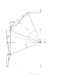
На фиг. 1 изображена схема положения части цепи при переходе от поступательного движения к вращательному движению. Угловое расстояние между зубцами ϕ принято равным 45 градусам. В начальном положении исходное звено расположено между точками А и Е. При повороте звездочки на угол ϕ/2=22.5 градусов звено должно перейти в положение ВС. Расстояние DC равно длине исходного звена, а это значит, что фактическая длина звена в положении ВС больше чем длина звена в начальном положении.In FIG. 1 shows a diagram of the position of a part of the chain during the transition from translational motion to rotary motion. The angular distance between the teeth ϕ is assumed to be 45 degrees. In the initial position, the initial link is located between points A and E. When the sprocket is turned by an angle ϕ / 2 = 22.5 degrees, the link should move to the BC position. The DC distance is equal to the length of the original link, which means that the actual length of the link in the BC position is greater than the length of the link in the initial position.
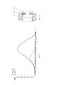
На фиг. 2 представлен график, показывающий изменение разности фактической длины и исходной длины звена, как разность между DC и ВС в зависимости от угла φ поворота звена. Из графика видно, что при ϕ=45 и φ=30 градусам и при смене поступательного движения и вращательного движения, разность сначала увеличивается, а затем уменьшается. Это характерно для любых значениях ϕ. Задачей, решаемой настоящим изобретением, является создание новой механической системы, решающей эту проблему.In FIG. 2 is a graph showing the change in the difference between the actual length and the original length of the link, as the difference between DC and BC, depending on the angle φ of the link rotation. It can be seen from the graph that at ϕ = 45 and φ = 30 degrees and with a change in translational motion and rotational motion, the difference first increases and then decreases. This is typical for any values of ϕ. The problem solved by the present invention is to create a new mechanical system that solves this problem.
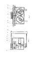
На фиг. 2, фиг. 3, фиг. 4 показано соединительное звено 17 в трех проекциях. Звено состоит из центрального стержня 2, к которому присоединяется гнездо 1 для зубца звездочки 15 и внешние различные устройства (на рисунке не показаны). Стержни 3 используются как оси для подвижных звеньев и связаны для жестокости перемычкой 4 с помощью резьбового соединения. Перемычка крепится после установки втулки 10 на стержни 3. На этих стержнях закреплены ограничители 19 и расположены защелки 7. Ограничитель 19 фиксирует положение подвижного звена в его крайнем положении при прямолинейном движении звена. На конце стержня 2 установлен шип 24, который при переходе от прямолинейного движения к вращательному перемещается вдоль стенок 23.In FIG. 2, fig. 3, fig. 4 shows the connecting
На фиг. 5, фиг. 6, фиг. 7 показано подвижное звено 16. Ось 11 подвижного звена соединена с втулкой 10. Ограничитель 5 обеспечивает односторонний поворот звена. На втулке закреплен штырь 12, который при переходе от прямолинейного движения к вращательному и наоборот, от вращательного к прямолинейному вставляется в направляющий профиль 13. Профиль это изогнутый швеллер, кривизна которого определяет передвижение подвижного звена вдоль оси 3 втулки 10.In FIG. 5, figs. 6, fig. 7 shows the
На фиг. 8, фиг. 9 показаны оба звена в собранном виде. Вокруг стержня 3 расположен гибкий кожух 8, который крепится как к втулке 10, так и к стержню 3 и заполняется маслом для смазки при движении втулки. Жесткий кожух 9, при необходимости, прикрепляемый к стержням 2 и 3, а также к перемычке 4, служит для предохранения гибкого кожуха. На этом кожухе сделаны прорези для движения подвижных звеньев и штырей 12, которые вставляются в профиль 13. С помощью стержней 14 профиль крепится к оси 18. В собранной цепи в начале каждого звена штыри закреплены по одну сторону от центра втулки, а в конце звена по другую сторону. В середине звена может располагаться стержень 22.In FIG. 8, figs. 9 shows both links assembled. Around the
На фиг. 10 изображена часть цепи при повороте звездочки на угол ϕ/2. Показан направляющий профиль 13 и его крепление 14 к оси 18 звездочки 15. В состав этого крепления входят стенки 23. Показаны соединительные звенья 17 и подвижные звенья 16. Длина подвижного звена между центрами осей звена равна L. При сдвиге звена 16 возникает момент вращения, который показан стрелкой. Для предотвращения поворота соединительного звена 17 используется ограничитель 5 левого звена и штырь 12 правого звена, положение которого определяется стенками профиля. На фиг. 15 изображена часть цепи в начальном положении поворота звездочки. Штырь 12 закреплен на стержне 22, расположенном в центре подвижного звена.In FIG. 10 shows a part of the chain when the sprocket is turned through an angle ϕ / 2. Shown is the
На фиг. 13 показана часть втулки. Угол 6 фаски и упругость кольца 21 защелки 7 определяют усилие, которое нужно приложить для сдвига подвижного звена. Кольцо 21 вставлено в канавку 20. При наличии усилия радиус неполного кольца 21 уменьшается и кольцо опускается в канавку 20 на стержне 3.In FIG. 13 shows part of the bushing. The
Движение цепи при переходе от прямолинейного движения к вращательному происходит в два этапа: пусть на первом этапе звенья цепи находятся в положении, изображенном на фиг. 1. Рассматривается звено, которое первоначально располагалось между точками А и Е. При движении на прямолинейном участке звено располагается между ограничителем 19 и защелкой 7. Пусть радиус звездочки R, а угловое расстояние ϕ между зубцами равно 45 градусам. Длина звена цепи L равна 2⋅sun(ϕ/2)-λ и равна 0,7653⋅R-λ. Величина λ это расстояние между центрами стержней 3, определяется диаметром втулки, как показано на фиг. 3, и значительно меньше R. Дуга ЕС это часть окружности, по которой проходит траектория движения центров осей подвижных звеньев, а дуга AD является копий дуги ЕС. Если начало звена перемещается по дуге ЕС, а конец звена, находящийся в точке А, будет перемещаться по дуге AD, то звено АЕ будет передвигаться параллельно самому себе, следовательно, никакого изменения длины не будет. При этом втулка конца подвижного звена 17 будет перемещаться по стержню 3 соединительного звена 17, как показано на фиг. 10. Для фиксации положения цепи стенка крепления 23 будет располагаться между шипом 24 и осью звездочки, тем самым препятствуя смещению звеньев цепи к центру. При повороте на угол равный φ звено расположится между точками A1 и E1, а при повороте на угол ϕ/2 звено займет положение DC и движение переходит на второй этап. Дуга DE является частью окружности, по которой проходят оси подвижных звеньев при вращении вокруг центра звездочки. Дальнейшее движение представляет собой вращение эвена. При дальнейшем повороте на угол равный ϕ/2 конец звена переместится по дуге DE в точку Е, а начало звена переместится из точки С по дуге СК в точку К и, в результате, звено будет располагаться между точками Е и K, а это значит, что переход от поступательного движения к вращательному для этого звена завершен. На втором этапе стенка 23 будет располагаться позади шипа 24, препятствуя смещению звеньев цепи от центра. Величина смещения звена между точками В и D это h=(1-cos((ϕ/2))⋅R и равно 0,07612⋅R. Такое движение конца звена достигается за счет того, что штырь втулки на конце звена вставлен в канавку профиля, кривизна которого обеспечивает заданное движение, а начало звена связано со звездочкой через соединительное звено. Так как штыри расположены по разные стороны от центра втулки, то при переходе от вращательного движения к поступательному штырь начала звена взаимодействует с профилем, а конец звена связан со звездочкой. Расположение штырей по отношению к центру втулки произвольное, но оно должно обеспечивать движение звена вдоль линий, показанных на фиг. 1.The movement of the chain during the transition from rectilinear movement to rotational movement occurs in two stages: at the first stage, let the chain links be in the position shown in Fig. 1. Consider a link, which was originally located between points A and E. When moving on a straight section, the link is located between the
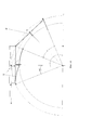
На фиг. 14 изображена схема положения части цепи при повороте звездочки на угол ϕ/2. Звено первоначально расположенное между точками А и Е перешло в положение DC. Стержень 22, который закреплен посредине подвижного звена, первоначально находился между точками В и D теперь располагается между точками B1 и D1. Длина его равна h, а на его конце располагается штырь 12. Так же как в предыдущем случае дуга DD1 соответствует дуге ЕС. Точка D1 находится на траектории вращения штыря, закрепленного на стержне 22. Передвижение штыря 12 по траектории профиля D1P обеспечивает вращение звена DC. В точке Р звено переходит в положение EK и располагается на соединительном звене между ограничителем 19 и защелкой 7, а соединительное звено сцепляется со звездочкой и в дальнейшем вращается как предыдущее звено CQ. На фиг. 15 показана часть звездочки при переходе от вращательного движения к прямолинейному. Штырь 12 левого звена входит в выемку профиля 13, а штырь правого звена выходит из профиля. В этом случае на каждом звене расположен только один штырь.FIG. 14 shows a diagram of the position of a part of the chain when the sprocket is turned through an angle ϕ / 2. The link originally located between points A and E has moved to position DC. The
Пусть скорость вращения звездочки в точке Е равна V и направлена горизонтально. Скорости точек D и С при вращении определяются положением радиусов DO и СО. Если угол поворота звездочки отсчитывать от линии ЕО, то горизонтальная составляющая скорости V1=V⋅cos(φ), а вертикальная V2=V⋅sin(φ), как показано на фиг. 1, где φ угол поворота звездочки. Поэтому для точки D горизонтальная скорость V1=V⋅cos(-ϕ/2+φ), а для точки С горизонтальная скорость V1=V⋅cos(ϕ/2+φ). При движении от точки А к точке D все звено передвигается параллельно самому себе, скорость движения цепи определяется скоростью точки начала звена и изменяется от V до V⋅cos(ϕ/2), или от V до 0,9238⋅V, а при движении от точки D до точки Е скорость зависит от горизонтальной скорости точки D и изменяется по формуле V⋅cos(-ϕ/2+φ) увеличиваясь от 0,9238⋅V до V. При переходе от вращательного движения к поступательному последовательность этапов меняется: сначала вращение, а потом движение параллельно себе.Let the speed of rotation of the asterisk at point E be equal to V and directed horizontally. The speeds of points D and C during rotation are determined by the position of the radii DO and CO. If the angle of rotation of the sprocket is counted from the line EO, then the horizontal component of the velocity V 1 = V⋅cos (φ), and the vertical V 2 = V⋅sin (φ), as shown in Fig. 1, where φ is the angle of rotation of the sprocket. Therefore, for point D, the horizontal speed is V 1 = V⋅cos (-ϕ / 2 + φ), and for point C, the horizontal speed is V 1 = V⋅cos (ϕ / 2 + φ). When moving from point A to point D, the entire link moves parallel to itself, the speed of the chain is determined by the speed of the point where the link starts and changes from V to V⋅cos (ϕ / 2), or from V to 0.9238⋅V, and when moving from point D to point E, the speed depends on the horizontal speed of point D and changes according to the formula V⋅cos (-ϕ / 2 + φ) increasing from 0.9238⋅V to V. When moving from rotary to translational motion, the sequence of stages changes: first rotation, and then movement parallel to itself.
На фиг. 11 изображена общая схема цепной передачи в момент поворота на угол равный ϕ/2. На схеме видно, что если ориентация и угловое расстояние между зубцами одинаково, то скорость вращения звездочек постоянна и не зависит от изменения скорости движения цепи. В точках U и F, U1 и F1 скорости одинаковы и направлена в право, а точках О и Р, O1 и P1 такая же скорость, но направлена в лево. Так звенья UF и О1Р1 будут вращаться и перейдут в QX и R1Y1 и их скорости будут определяться в точках, расположенных на траектории вращения зубцов звездочки, а ОР и U1F1 будут перемещаться параллельно самим себе и перейдут в положение RY и Q1X1, а скорости их будут определяться в точках, Р и U1 расположенных на траектории вращения зубцов звездочки. Одинаковая ориентация достигается, когда количество подвижных в цепи звеньев четное и 180/ϕ целое число, а звездочки расположены как показано на фиг. 11.FIG. 11 shows the general diagram of the chain transmission at the moment of turning through an angle equal to ϕ / 2. The diagram shows that if the orientation and angular distance between the teeth are the same, then the speed of rotation of the sprockets is constant and does not depend on the change in the speed of the chain. At points U and F, U 1 and F 1 the speeds are the same and directed to the right, and points O and P, O 1 and P 1 are the same speed, but directed to the left. So the links UF and O 1 P 1 will rotate and go into QX and R 1 Y 1 and their speeds will be determined at points located on the trajectory of rotation of the teeth of the sprocket, and OP and U 1 F 1 will move parallel to themselves and move to the position RY and Q 1 X 1 , and their speeds will be determined at points P and U 1 located on the trajectory of rotation of the sprocket teeth. The same orientation is achieved when the number of movable links in the chain is even and 180 / ϕ is an integer, and the sprockets are located as shown in FIG. eleven.
Если скорость движения цепи V задана внешним устройством, то угловая скорость вращения звездочек Ω изменяется в соответствии с формулой Ω=(V/R)⋅cos(φ) на первом этапе и Ω=(V/R)⋅cos(-ϕ/2+φ)) на втором этапе, где φ изменяется от 0 до ϕ/2.If the chain speed V is set by an external device, then the angular rotation speed of the sprockets Ω changes in accordance with the formula Ω = (V / R) ⋅cos (φ) at the first stage and Ω = (V / R) ⋅cos (-ϕ / 2 + φ)) at the second stage, where φ varies from 0 to ϕ / 2.
Claims (3)
Priority Applications (1)
| Application Number | Priority Date | Filing Date | Title |
|---|---|---|---|
| RU2019140900A RU2726503C1 (en) | 2019-12-11 | 2019-12-11 | Chain transmission with links of large size |
Applications Claiming Priority (1)
| Application Number | Priority Date | Filing Date | Title |
|---|---|---|---|
| RU2019140900A RU2726503C1 (en) | 2019-12-11 | 2019-12-11 | Chain transmission with links of large size |
Publications (1)
| Publication Number | Publication Date |
|---|---|
| RU2726503C1 true RU2726503C1 (en) | 2020-07-14 |
Family
ID=71616764
Family Applications (1)
| Application Number | Title | Priority Date | Filing Date |
|---|---|---|---|
| RU2019140900A RU2726503C1 (en) | 2019-12-11 | 2019-12-11 | Chain transmission with links of large size |
Country Status (1)
| Country | Link |
|---|---|
| RU (1) | RU2726503C1 (en) |
Cited By (1)
| Publication number | Priority date | Publication date | Assignee | Title |
|---|---|---|---|---|
| RU2775281C1 (en) * | 2022-02-03 | 2022-06-29 | Владимир Митрофанович Борисов | Chain drive with large links |
Citations (4)
| Publication number | Priority date | Publication date | Assignee | Title |
|---|---|---|---|---|
| RU2303726C1 (en) * | 2006-05-10 | 2007-07-27 | Федеральное государственное образовательное учреждение высшего профессионального образования "Азово-Черноморская государственная агроинженерная академия" (ФГОУ ВПО АЧГАА) | Bushing-roller chain |
| RU2318145C2 (en) * | 2002-05-03 | 2008-02-27 | Теодорус Хенрикус Йоханнес Каролина КОРСЕ | Chain transmission and chain |
| RU2455542C1 (en) * | 2011-01-12 | 2012-07-10 | Сергей Петрович Кулагин | Chain transmission |
| US8491430B1 (en) * | 2010-01-22 | 2013-07-23 | Kevin Eugene Swartz | Roller chain assembly |
-
2019
- 2019-12-11 RU RU2019140900A patent/RU2726503C1/en active
Patent Citations (4)
| Publication number | Priority date | Publication date | Assignee | Title |
|---|---|---|---|---|
| RU2318145C2 (en) * | 2002-05-03 | 2008-02-27 | Теодорус Хенрикус Йоханнес Каролина КОРСЕ | Chain transmission and chain |
| RU2303726C1 (en) * | 2006-05-10 | 2007-07-27 | Федеральное государственное образовательное учреждение высшего профессионального образования "Азово-Черноморская государственная агроинженерная академия" (ФГОУ ВПО АЧГАА) | Bushing-roller chain |
| US8491430B1 (en) * | 2010-01-22 | 2013-07-23 | Kevin Eugene Swartz | Roller chain assembly |
| RU2455542C1 (en) * | 2011-01-12 | 2012-07-10 | Сергей Петрович Кулагин | Chain transmission |
Cited By (2)
| Publication number | Priority date | Publication date | Assignee | Title |
|---|---|---|---|---|
| RU2778162C1 (en) * | 2021-12-13 | 2022-08-15 | Владимир Митрофанович Борисов | Chain transmission sections with large-sized links |
| RU2775281C1 (en) * | 2022-02-03 | 2022-06-29 | Владимир Митрофанович Борисов | Chain drive with large links |
Similar Documents
| Publication | Publication Date | Title |
|---|---|---|
| RU2735785C1 (en) | Spiral conveyor mesh | |
| RU2726503C1 (en) | Chain transmission with links of large size | |
| RU2018138792A (en) | KINEMATIC CHAIN FOR TRANSMISSION OF MECHANICAL TORQUES | |
| CN115476384A (en) | A synchronous rope-driven single-degree-of-freedom rotary joint | |
| US2299563A (en) | Reversing gear mechanism | |
| US1877338A (en) | Chain drive | |
| CN107816513B (en) | A gear transmission mechanism whose transmission ratio decreases with increasing speed | |
| RU2374526C2 (en) | Mechanism for movement transformation | |
| EA030873B1 (en) | Transmission gear, roller reducer comprising the transmission gear, and method of assembly thereof | |
| US2464584A (en) | Gear stop mechanism | |
| KR100876340B1 (en) | Tooth assembly | |
| RU2683896C1 (en) | Mechanism for transferring rotation between parallel shafts | |
| WO2021166539A1 (en) | Transmission mechanism | |
| KR101717158B1 (en) | Joint Assembly Having Linear-Driving Inducing Yoke | |
| RU2635753C2 (en) | Wind turbine with gearbox of single-stage speed multiplier with high gear ratio | |
| RU2641563C2 (en) | Gear-cog step drive with mechanical excitation and zero reverse effort | |
| RU2626434C2 (en) | Multi-purpose self-aligning system with foundations common not changed axis of rotation | |
| WO2011049341A2 (en) | Gear device which enables the reciprocating angular motion of a slave shaft | |
| US2523231A (en) | Mechanism for transforming continuous rotary motion into reciprocating motion | |
| RU2643097C2 (en) | Continuously variable transmission with third gears | |
| US20150107953A1 (en) | Eccentric Lock One Way Clutch | |
| SE433393B (en) | Movement transforming mechanism | |
| US4229982A (en) | Cam drive system having parallel input and output shafts | |
| SU1099162A1 (en) | Mechanical drive for rotary plug tap with conical plug | |
| SU1293424A1 (en) | Transmission |