RU2692457C2 - Device and method for manufacturing of interdental cleaner - Google Patents
Device and method for manufacturing of interdental cleaner Download PDFInfo
- Publication number
- RU2692457C2 RU2692457C2 RU2017121859A RU2017121859A RU2692457C2 RU 2692457 C2 RU2692457 C2 RU 2692457C2 RU 2017121859 A RU2017121859 A RU 2017121859A RU 2017121859 A RU2017121859 A RU 2017121859A RU 2692457 C2 RU2692457 C2 RU 2692457C2
- Authority
- RU
- Russia
- Prior art keywords
- filaments
- positioning
- rod
- bundles
- field
- Prior art date
Links
Images

Classifications
-
- B—PERFORMING OPERATIONS; TRANSPORTING
- B29—WORKING OF PLASTICS; WORKING OF SUBSTANCES IN A PLASTIC STATE IN GENERAL
- B29C—SHAPING OR JOINING OF PLASTICS; SHAPING OF MATERIAL IN A PLASTIC STATE, NOT OTHERWISE PROVIDED FOR; AFTER-TREATMENT OF THE SHAPED PRODUCTS, e.g. REPAIRING
- B29C45/00—Injection moulding, i.e. forcing the required volume of moulding material through a nozzle into a closed mould; Apparatus therefor
- B29C45/14—Injection moulding, i.e. forcing the required volume of moulding material through a nozzle into a closed mould; Apparatus therefor incorporating preformed parts or layers, e.g. injection moulding around inserts or for coating articles
- B29C45/14065—Positioning or centering articles in the mould
-
- A—HUMAN NECESSITIES
- A46—BRUSHWARE
- A46B—BRUSHES
- A46B9/00—Arrangements of the bristles in the brush body
- A46B9/06—Arrangement of mixed bristles or tufts of bristles, e.g. wire, fibre, rubber
-
- A—HUMAN NECESSITIES
- A46—BRUSHWARE
- A46B—BRUSHES
- A46B1/00—Brush bodies and bristles moulded as a unit
-
- A—HUMAN NECESSITIES
- A46—BRUSHWARE
- A46B—BRUSHES
- A46B3/00—Brushes characterised by the way in which the bristles are fixed or joined in or on the brush body or carrier
- A46B3/005—Bristle carriers and bristles moulded as a unit
-
- A—HUMAN NECESSITIES
- A46—BRUSHWARE
- A46B—BRUSHES
- A46B3/00—Brushes characterised by the way in which the bristles are fixed or joined in or on the brush body or carrier
- A46B3/04—Brushes characterised by the way in which the bristles are fixed or joined in or on the brush body or carrier by mouldable materials, e.g. metals, cellulose derivatives, plastics
-
- A—HUMAN NECESSITIES
- A46—BRUSHWARE
- A46B—BRUSHES
- A46B9/00—Arrangements of the bristles in the brush body
- A46B9/02—Position or arrangement of bristles in relation to surface of the brush body, e.g. inclined, in rows, in groups
- A46B9/026—Position or arrangement of bristles in relation to surface of the brush body, e.g. inclined, in rows, in groups where the surface of the brush body or carrier is not in one plane, e.g. not flat
-
- A—HUMAN NECESSITIES
- A46—BRUSHWARE
- A46B—BRUSHES
- A46B9/00—Arrangements of the bristles in the brush body
- A46B9/02—Position or arrangement of bristles in relation to surface of the brush body, e.g. inclined, in rows, in groups
- A46B9/04—Arranged like in or for toothbrushes
-
- A—HUMAN NECESSITIES
- A46—BRUSHWARE
- A46D—MANUFACTURE OF BRUSHES
- A46D3/00—Preparing, i.e. Manufacturing brush bodies
- A46D3/04—Machines for inserting or fixing bristles in bodies
-
- B—PERFORMING OPERATIONS; TRANSPORTING
- B29—WORKING OF PLASTICS; WORKING OF SUBSTANCES IN A PLASTIC STATE IN GENERAL
- B29C—SHAPING OR JOINING OF PLASTICS; SHAPING OF MATERIAL IN A PLASTIC STATE, NOT OTHERWISE PROVIDED FOR; AFTER-TREATMENT OF THE SHAPED PRODUCTS, e.g. REPAIRING
- B29C45/00—Injection moulding, i.e. forcing the required volume of moulding material through a nozzle into a closed mould; Apparatus therefor
- B29C45/0081—Injection moulding, i.e. forcing the required volume of moulding material through a nozzle into a closed mould; Apparatus therefor of objects with parts connected by a thin section, e.g. hinge, tear line
-
- A—HUMAN NECESSITIES
- A46—BRUSHWARE
- A46B—BRUSHES
- A46B2200/00—Brushes characterized by their functions, uses or applications
- A46B2200/10—For human or animal care
- A46B2200/1066—Toothbrush for cleaning the teeth or dentures
- A46B2200/108—Inter-dental toothbrush, i.e. for cleaning interdental spaces specifically
-
- B—PERFORMING OPERATIONS; TRANSPORTING
- B29—WORKING OF PLASTICS; WORKING OF SUBSTANCES IN A PLASTIC STATE IN GENERAL
- B29C—SHAPING OR JOINING OF PLASTICS; SHAPING OF MATERIAL IN A PLASTIC STATE, NOT OTHERWISE PROVIDED FOR; AFTER-TREATMENT OF THE SHAPED PRODUCTS, e.g. REPAIRING
- B29C45/00—Injection moulding, i.e. forcing the required volume of moulding material through a nozzle into a closed mould; Apparatus therefor
- B29C45/14—Injection moulding, i.e. forcing the required volume of moulding material through a nozzle into a closed mould; Apparatus therefor incorporating preformed parts or layers, e.g. injection moulding around inserts or for coating articles
- B29C45/14065—Positioning or centering articles in the mould
- B29C2045/14139—Positioning or centering articles in the mould positioning inserts having a part extending into a positioning cavity outside the mould cavity
Abstract
Description
Область техники, к которой относится изобретение The technical field to which the invention relates.
Изобретение относится к устройству для изготовления соответствующего межзубного очистителя, а также к способу изготовления межзубного очистителя, который содержит носитель в форме стержня из полимерного материала, в который внедрены выступающие в боковых направлениях щетины.The invention relates to a device for the manufacture of an appropriate interdental cleaner, as well as to a method for manufacturing an interdental cleaner, which contains a carrier in the form of a rod of polymeric material in which bristles projecting in lateral directions are embedded.
Уровень техники The level of technology
Соответствующий межзубный очиститель часто называют также зубочисткой и она известна, например, из документа ЕР 0 932 371 В1. Описанный там межзубный очиститель содержит носитель в форме стержня из стабильного по форме полимерного материала, который содержит на одном своем конце часть для захватывания и на своем аксиально противоположном конце чистящее устройство в форме покрытия носителя. Покрытие состоит из мягко-упругого полимерного материала, например, термопластичного эластомера, и напылено на носитель. На своей наружной стороне покрытие содержит структурирование в форме утолщения или простирающихся радиально наружу пальцев. Для чистки межзубных пространств пользователь захватывает межзубный очиститель за часть для захватывания и вводит имеющий форму стержня носитель с несущим покрытие концом в межзубное пространство и перемещает межзубный очиститель в аксиальном направлении с возвратно-поступательным движением, за счет чего происходит чистка межзубного пространства и удаление возможно присутствующих частиц.The corresponding interdental cleaner is also often referred to as a toothpick and is known, for example, from EP 0 932 371 B1. The interdental cleaner described therein comprises a rod-shaped carrier of a form-stable polymeric material that contains at one end a grasping part and at its axially opposite end a cleaning device in the form of a carrier coating. The coating consists of a soft-elastic polymer material, for example, a thermoplastic elastomer, and is sprayed onto the carrier. On its outer side, the coating contains structuring in the form of a thickening or fingers extending radially outwards. To clean the interdental spaces, the user grasps the interdental cleaner for the grabbing part and inserts a rod-shaped carrier with a bearing end into the interdental space and moves the interdental cleaner in the axial direction with reciprocating movement, due to which the interdental space is cleaned and particles that may be present are removed .
Было установлено, что с помощью межзубного очистителя с названной структурой возможна хорошая очистка межзубных пространств, однако, затруднительным является удаление загрязнений или отложений из весьма узких, малых по величине карманов челюсти. В DE 10 2012 015 663 A1 предложен межзубный очиститель, чистящее устройство которого содержит комплект щетин с несколькими выступающими с радиальными компонентами от покрытия пучками щетин и/или отдельными щетинами. При этом само чистящее устройство может состоять из комплекта щетин, однако, возможно также предусмотрение дополнительно к комплекту щетин мягко-упругого покрытия с названной структурой.It was found that with the help of an interdental cleaner with the above structure, good cleaning of interdental spaces is possible, however, it is difficult to remove contaminants or deposits from the very narrow, small pockets of the jaw. In DE 10 2012 015 663 A1, an interdental cleaner is provided whose cleaning device contains a set of bristles with several protruding bristles and / or individual bristles with radial components from the coating. In this case, the cleaning device itself may consist of a set of bristles, however, it is also possible to provide, in addition to the set of bristles, a soft-elastic coating with the said structure.
Поскольку размеры межзубного очистителя относительно малы, оказалось затруднительным и затратным в техническом отношении точное выравнивание и удержание щетин при изготовлении межзубного очистителя в устройстве литья под давлением с тем, чтобы предотвратить при впрыске полимерного материала их сдвигание или смещение.Since the dimensions of the interdental cleaner are relatively small, it turned out to be difficult and technically expensive to precisely align and retain the bristles when the interdental cleaner is made in the injection molding device so as to prevent the polymer material from being displaced or displaced.
Раскрытие изобретения DISCLOSURE OF INVENTION
Задачей изобретения является создание способа и устройства для изготовления межзубного очистителя с названной структурой, при котором комплект щетин межзубного очистителя можно при его изготовлении несложным образом и надежно позиционировать и фиксировать. В соответствии с этим должно быть создано устройство для изготовления соответствующего межзубного очистителя, при котором возможно несложное осуществление способа. The objective of the invention is the creation of a method and device for the manufacture of interdental cleaner with the named structure, in which the set of bristles of the interdental cleaner can be easily and reliably positioned and fixed during its manufacture. In accordance with this, a device must be created for the manufacture of an appropriate interdental cleaner, in which the simple implementation of the method is possible.
С технологической точки зрения названную задачу решают с помощью способа с признаками п. 1. При этом предусмотрено, что поле филаментов, состоящее из нескольких пучков филаментов, вставляют в фиксирующую кассету и с помощью, по меньшей мере, одного фиксирующего устройства фиксируют в фиксирующей кассете с заранее заданной ориентацией. В завершение фиксирующую кассету вставляют в устройство литья под давлением и поле филаментов в устройстве литья под давлением опрыскивают полимерным материалом с образованием нескольких, расположенных на расстоянии друг от друга носителей в форме стержня. В завершение образующие поле филаментов пучки филаментов отделяют, по меньшей мере, на участках, расположенных между соседними носителями в форме стержня, в результате чего носители в форме стержня и, тем самым, межзубные очистители отделяют от поля филаментов или происходит разъединение этого поля.From a technological point of view, this problem is solved using the method with the signs of item 1. It is provided that the field of filaments, consisting of several bundles of filaments, is inserted into a fixing cassette and using at least one fixing device is fixed in a fixing cassette predetermined orientation. In conclusion, the locking cassette is inserted into the injection molding device and the field of the filaments in the injection molding device is sprayed with a polymeric material with the formation of several media in the form of a rod spaced from each other. Finally, filament bundles forming the field of filaments are separated, at least in areas located between adjacent carriers in the form of a rod, resulting in rod-shaped carriers and, thus, interdental cleaners are separated from the field of filaments or separation of this field occurs.
Изобретение исходит из основополагающей идеи одновременного исполнения нескольких межзубных очистителей без необходимости выравнивания для этого филаментов или щетин каждого отдельного межзубного очистителя, а использования поля филаментов из нескольких длинных, расположенных предпочтительно параллельно друг другу и на расстоянии друг от друга пучков филаментов. Точное позиционирование и фиксация поля филаментов или пучков филаментов в сравнении с манипуляциями с весьма короткими раскроенными щетинами являются существенно более простыми, надежными и точными. Еще соединяющие между собой отдельные межзубные очистители пучки филаментов разрезают и разделяют только после готового исполнения межзубных очистителей, так что на каждом отдельном межзубном очистителе образован радиальный или, по меньшей мере, выступающий с радиальными компонентами наружу комплект щетин.The invention proceeds from the fundamental idea of the simultaneous execution of several interdental cleaners without the need to align the filaments or bristles of each individual interdental cleaner, and to use a field of filaments of several long, preferably arranged parallel to each other and at a distance from each other filament bundles. The exact positioning and fixation of the field of the filaments or bundles of filaments in comparison with the manipulations with very short cut bristles are much simpler, reliable and accurate. Still interconnected separate interdental cleaners, filament bundles are cut and separated only after the finished execution of interdental cleaners, so that on each individual interdental cleaner there is a radial or at least protruding set of bristles protruding from the radial components.
Для фиксации поля филамента предусмотрена фиксирующая кассета, которую на удалении от устройства литья под давлением можно загружать полем филаментов или пучками филаментов. При этом может быть предусмотрено, что каждый пучок филаментов, по меньшей мере, в двух расположенных на расстоянии друг от друга областях его аксиальной длины вставляют соответственно в направляющую часть фиксирующей кассеты и фиксируют таким образом, что он свободно натянут между направляющими частями. Направляющие части обеспечивают точную позицию пучков филаментов и, в частности, точную взаимную ориентацию.For fixing the filament field, a fixing cassette is provided, which, away from the injection molding device, can be loaded with a field of filaments or bundles of filaments. In this case, it may be provided that each bundle of filaments, at least in two regions of its axial length at a distance from each other, is inserted respectively into the guide part of the fixing cassette and fixed in such a way that it is freely tensioned between the guide parts. The guide parts provide the exact position of the filament bundles and, in particular, the exact mutual orientation.
В усовершенствовании может быть предусмотрено, что направляющие части содержат соответственно несколько направляющих шлицев, причем каждый пучок филаментов вставляют в направляющий шлиц и точно позиционируют с его помощью.In the improvement, it can be provided that the guide portions contain, respectively, several guide slots, with each bundle of filaments inserted into the guide slot and precisely positioned with it.
Загруженную полем филаментов или пучками филаментов фиксирующую кассету вставляют в устройство литья под давлением и там опрыскивают полимерным материалом, который образует несколько носителей в форме стержня, расположенных рядом друг с другом на расстоянии друг от друга. После открывания устройства литья под давлением в фиксирующей кассете, далее, закреплено поле филаментов, причем теперь на поле филаментов нанесены несколько независимых, расположенных рядом друг с другом носителей в форме стержня, которые проходят предпочтительно перпендикулярно к продольной протяженности пучков филаментов.A fixing cassette loaded with a field of filaments or bundles of filaments is inserted into an injection molding device and sprayed there with a polymeric material that forms several rod-shaped carriers located next to each other at a distance from each other. After opening the injection molding device in the locking cassette, then the field of filaments is fixed, and now several independent, rod-shaped carriers are placed on the field of filaments, which preferably extend perpendicular to the longitudinal length of the filament bundles.
Один пучок филаментов может быть образован, например, одним моноволокном, то есть отдельной полимерной нитью, или пучком моноволокна, то есть несколькими расположенными рядом друг с другом полимерными нитями. Альтернативно возможно также, что пучок филаментов образован комплексным филаментом, который состоит из нескольких, проходящих рядом друг с другом моноволокон, которые соединены между собой или расположены рядом друг с другом. Отдельные филаменты могут при этом проходить прямолинейно или параллельно друг другу или могут быть также повернуты или скручены или текстурированы. Альтернативно или дополнительно к этому может быть предусмотрено, что отдельные филаменты одного пучка филаментов имеют различный диаметр и/или состоят из различных материалов. Однако, возможно также, что отдельные филаменты внутри одного пучка филаментов выполнены одинаковым образом, однако, отличаются от филаментов соседнего пучка филаментов диаметром и/или материалом.One bundle of filaments can be formed, for example, by a single monofilament, i.e., a single polymeric filament, or a monofilament bundle, i.e., several polymeric filaments located next to each other. Alternatively, it is also possible that the filament bundle is formed by a complex filament, which consists of several monofilaments passing next to each other, which are interconnected or are located next to each other. The individual filaments can thus be held straight or parallel to each other or can also be rotated or twisted or textured. Alternatively or additionally, it may be provided that the individual filaments of one bundle of filaments have a different diameter and / or consist of different materials. However, it is also possible that the individual filaments inside one bundle of filaments are made in the same way, however, they differ from the filaments of the adjacent bundle of filaments in diameter and / or material.
Если отдельные пучки филаментов поля филаментов, по меньшей мере, в двух расположенных на расстоянии друг от друга областях и предпочтительно в их концевых областях их аксиальной длины вставлены и зафиксированы в одной из направляющих частей, то они простираются между направляющими частями прямолинейно и под напряжением. В не нагруженном состоянии это обеспечивает точное взаимное позиционирование пучков филаментов. Если, однако, пучки филаментов являются относительно длинными и если образующий носители в форме стержня полимерный материал вводят с высоким давлением в соответствующую полость устройства для литья под давлением, то может произойти смещение пучков филаментов относительно друг друга, в результате чего точное позиционирование более не было бы возможным. В предпочтительном исполнении изобретения по этой причине предусмотрено, что каждый пучок филаментов поля филаментов при вставлении фиксирующей кассеты в устройство литья под давлением вставляют в несколько первых позиционирующих частей расположенных на расстоянии друг от друга и выполненные в устройстве литья под давлением. Первые позиционирующие части могут содержать, например, несколько первых позиционирующих шлицев, причем каждый пучок филаментов вставляют в один из первых позиционирующих шлицев первых позиционирующих частей предпочтительно с узкой посадкой. Таким образом обеспечивают точное направление и позиционирование относительно друг друга пучков филамента также в нескольких местах их участков, свободно закрепленных между направляющими частями фиксирующей кассеты, в результате чего надежно предотвращают непреднамеренное смещение вследствие внешних влияний или вследствие воздействия давления впрыска полимерного материала, образующего имеющий форму стержня носитель.If individual filament bundles of a field of filaments in at least two regions located at a distance from each other, and preferably in their end regions of their axial length, are inserted and fixed in one of the guide portions, then they extend between the guide portions linearly and under voltage. In the unloaded state, this ensures precise mutual positioning of the filament bundles. If, however, the filament bundles are relatively long and if a core-shaped carrier material is injected with high pressure into the corresponding cavity of the injection molding device, then the filament bundles can move relative to each other, resulting in no more accurate positioning. possible. In a preferred embodiment of the invention, for this reason, it is provided that each beam of filaments of the field of filaments is inserted into several first positioning parts spaced apart from one another and formed in an injection molding device when the fixing cassette is inserted into the injection molding device. The first positioning parts may comprise, for example, several first positioning splines, with each bundle of filaments inserted into one of the first positioning splines of the first positioning parts, preferably with a narrow fit. In this way, the filament bundles are precisely guided and positioned relative to each other also in several places of their sections freely fixed between the guiding parts of the fixing cassette, thus reliably preventing unintentional displacement due to external influences or due to the injection pressure of a polymeric material forming a rod-shaped carrier .
Простое и надежное вставление пучков филаментов в первые позиционирующие шлицы первых позиционирующих частей может быть достигнуто, если верхние стороны первых позиционирующих частей расположены в направлении вставления смещенными относительно друг друга в направлении по высоте, так что пучки филаментов при вставлении или опускании фиксирующей кассеты не вводят одновременно во все их первые позиционирующие шлицы, а присутствует боковое смещение.Simple and reliable insertion of the filament bundles into the first positioning slots of the first positioning portions can be achieved if the upper sides of the first positioning portions are arranged in the direction of insertion displaced relative to each other in the height direction, so that the filament bundles do not enter simultaneously in the insertion or lowering of the fixing cassette. all their first positioning splines, and lateral displacement present.
В усовершенствовании изобретения может быть предусмотрено, что носитель в форме стержня содержит на своем обращенном от щетин конце имеющий предпочтительно форму пластины участок для захватывания. Каждый носитель в форме стержня может быть соответственно независимо от других носителей в форме стержня выполнен в качестве отдельного носителя, однако, предпочтительно предусмотрено, что соседние носители в форме стержня соединяют друг с другом на их участках для захватывания в виде монолитной детали. Это может быть осуществлено, например, за счет того, что соседние носители соединяют между собой на их участках для захватывания с помощью обламываемых перемычек. При извлечении натянутого в фиксирующей кассете поля филаментов с отлитыми носителями в форме стержня из устройства литья под давлением носители в форме стержня соединены в форме цельного элемента на их переднем, обращенном от участка для захватывания конце с полем филаментов или пучками филаментов и свободно выступают перпендикулярно им. Если носители в форме стержня дополнительно названным образом соединены друг с другом на их участках для захватывания, то возникает дополнительная фиксация и взаимное подпирание носителей в форме стержня, в результате чего, с одной стороны, предотвращается изгибание под воздействием продольной нагрузки или отламывание одного из носителей в форме стержня вследствие точечной внешней нагрузки, или возникновение обычным образом относительных смещений между носителями в форме стержня. Тем самым носители в форме стержня удерживают в заранее определенной относительной позиции, что особенно предпочтительно в случае, если фиксирующую кассету после извлечения из устройства литья под давлением подводят к следующей рабочей секции, в которой, например, может производиться отливка следующего компонента из полимерного материала или в которой производят раскрой межзубных очистителей.In an improvement of the invention, it may be provided that the support in the form of a rod comprises, at its end facing away from the bristles, a preferably plate-shaped gripping portion. Each carrier in the form of a rod can be suitably independent of other carriers in the form of a rod, made as a separate carrier, however, it is preferable that adjacent carriers in the form of a rod are connected to each other in their sections for gripping as a monolithic part. This can be accomplished, for example, due to the fact that adjacent carriers are interconnected at their sites for capturing using breakable jumpers. When extracting a field of filaments stretched in a fixing cassette with molded carriers in the form of a rod from the injection molding device, the carriers in the form of a rod are connected in the form of a single element at their front, facing away from the gripping end with the field of filaments or bundles of filaments and freely act perpendicular to them. If the rod-shaped carriers are additionally connected to each other in their portions for grabbing, then additional fixation and mutual support of the rod-shaped carriers occurs, as a result of which, on the one hand, bending under the influence of longitudinal load or breaking off of one of the carriers is prevented the shape of the rod due to a point external load, or the occurrence in the usual way of relative displacements between carriers in the form of a rod. Thus, the rod-shaped carriers are held in a predetermined relative position, which is particularly preferable in the case where the fixing cassette, after being removed from the injection molding device, is fed to the next working section, in which, for example, the next component can be cast from a polymeric material or which produce cutting interdental cleaners.
Для отливки следующего компонента из полимерного материала в соответствии с изобретением может быть предусмотрено, что фиксирующую кассету с полем филаментов, несущим носители в форме стержня, либо перемещают в устройстве литья под давлением, в котором отливают носители в форме стержня, либо вставляют в следующее устройство литья под давлением. При этом носители в форме стержня предпочтительно в области поля филаментов, по меньшей мере, на участках опрыскивают мягко-упругим полимерным материалом, например, термопластичным эластомером или силиконом, с образованием покрытия. Соответствующее покрытие может, например, окружать в форме гильзы передний, обращенный от участка для захвата конец носителя в форме стержня и содержать на наружной стороне радиально выступающие выступы или пальцы.For casting the next component from a polymeric material in accordance with the invention, it may be provided that a fixing cartridge with a field of filaments carrying carriers in the form of a rod, or move in an injection molding device, in which media are cast in the form of a rod, or inserted into the next molding device under pressure. In this case, rod-shaped carriers, preferably in the field of the filament field, are sprayed at least in the areas with a soft-elastic polymer material, for example, a thermoplastic elastomer or silicone, to form a coating. A suitable coating may, for example, surround the sleeve, in the form of a sleeve, facing the grip end of the carrier in the form of a rod and contain radially protrusions or fingers on the outside.
Также и при впрыске мягко-упругого полимерного материала для образования покрытия каждый пучок филаментов поля филаментов должен быть надежно позиционирован. Это может быть достигнуто, например, за счет того каждый пучок филаментов поля филаментов при вставлении или перемещении фиксирующей кассеты вставляют в несколько расположенных на расстоянии друг от друга, выполненные на устройстве литья под давлением или на следующем устройстве литья под давлением вторые позиционирующие части.Also, when a soft-elastic polymer material is injected, each bundle of filament field filaments must be securely positioned to form a coating. This can be achieved, for example, due to the fact that each filament bundle of the field of filaments is inserted into several second positioning parts located at a distance from each other when inserting or moving the fixing cassette.
При этом может быть предусмотрено, что каждая вторая позиционирующая часть содержит несколько вторых позиционирующих шлицев, причем каждый пучок филаментов вставляют предпочтительно с узкой посадкой в один из вторых позиционирующих шлицев вторых позиционирующих частей.In this case, it can be provided that each second positioning part contains several second positioning slots, with each bundle of filaments inserted preferably with a narrow fit into one of the second positioning slots of the second positioning parts.
После завершения процессов впрыска образуется конструкция из нескольких, расположенных рядом друг с другом носителей в форме стержня с покрытием или без него, которые еще соединены между собой с помощью пучков филаментов. В ходе процесса разрезания производят разрезание и разделение образующих поле филаментов пучков филаментов, по меньшей мере, на расположенных между соседними, имеющими форму стержня носителя участках, и предпочтительно также на их концевых участках. При этом разделение пучков филаментов можно производить непосредственно в фиксирующей кассете, то есть в течение времени, пока пучки филаментов еще зафиксированы в фиксирующей кассете. Альтернативно возможно, однако, также, что несущее носители в форме стержня поле филаментов перед разделением пучков филаментов извлекают из фиксирующей кассеты и процесс разрезания производят в отдельной рабочей секции. Затем порожняя фиксирующая кассета может быть загружена новыми пучками филаментов. Предпочтительно каждый носитель в форме стержня отделяют от поля филаментов посредством двух разрезов, которые проходят, например, на незначительном расстоянии параллельно его наружному контуру или наружному контуру покрытия, так что на носителе в форме стержня образуется комплект щетин, выступающий радиально наружу.After completion of the injection processes, a structure is formed of several, side-by-side carriers in the form of a rod with or without coating, which are still interconnected by means of filament bundles. During the cutting process, filament bundles of filaments forming the field of the filaments are cut and separated, at least between the adjacent, rod-shaped sections of the carrier, and preferably also at their end sections. In this case, the separation of the filament bundles can be carried out directly in the fixing cassette, that is, during the time that the filament bundles are still fixed in the fixing cassette. Alternatively, it is also possible, however, that the carrier field in the form of a rod, the field of filaments, before separation of the bundles of filaments is removed from the fixing cassette and the cutting process is carried out in a separate working section. Then the empty fixing cassette can be loaded with new filament bundles. Preferably, each rod-shaped carrier is separated from the field of the filaments by means of two cuts, which extend, for example, at an insignificant distance parallel to its outer contour or outer contour of the coating, so that a set of bristles protruding radially outwards forms on the rod-shaped carrier.
Устройство для изготовления соответствующего изобретению межзубного очистителя содержит в соответствии с изобретением устройство литья под давлением, которое содержит, по меньшей мере, одну полость для исполнения нескольких, расположенных рядом друг с другом носителей в форме стержня, и фиксирующее устройство для поля филаментов, образованного несколькими пучками филаментов. При этом фиксирующее устройство содержит фиксирующую кассету с, по меньшей мере, двумя расположенными на расстоянии друг от друга направляющими частями, в которые могут быть вставлены пучки филаментов, причем пучки филаментов могут фиксироваться в фиксирующем устройстве таким образом, что они могут быть свободно натянуты между направляющими частями. Фиксирующая кассета может быть вставлена в устройство литья под давлением и может быть извлечена из него и/или перемещена в нем.An apparatus for manufacturing an interdental cleaner according to the invention comprises, in accordance with the invention, an injection molding device which comprises at least one cavity for executing several rod-shaped carriers arranged next to each other and a fixing device for a field of filaments formed by several bundles filaments. In this case, the locking device contains a locking cassette with at least two spaced apart guide parts into which filament bundles can be inserted, with the filament bundles being fixed in the fixing device so that they can be freely tensioned between the guides. in parts. The locking cassette can be inserted into the injection molding device and can be removed from it and / or moved in it.
Образованное несколькими пучками филаментов поле филаментов может быть вставлено вне установки литья под давлением в фиксирующую кассету и фиксироваться в ней. При этом направляющие части обеспечивают позиционирование пучков филаментов с заранее определенной ориентацией. С этой целью направляющие части могут содержать несколько расположенных рядом друг с другом направляющих шлицев, причем каждый направляющий шлиц может быть выполнен для приема ровно одного пучка филаментов.The field of filaments formed by several bundles of filaments can be inserted outside the installation of injection molding into the fixing cassette and fixed in it. In this case, the guide portions provide positioning of the filament bundles with a predetermined orientation. To this end, the guide portions may comprise several guide slots adjacent to each other, each guide slot may be made to receive exactly one bundle of filaments.
Фиксацию пучков филаментов в фиксирующей кассета осуществляют предпочтительно с помощью зажимной части, которая фиксирует пучки филаментов в фиксирующей кассете с зажимом и, таким образом, с силовым замыканием.The fixation of the filament bundles in the fixing cassette is carried out preferably with the aid of a clamping part, which fixes the filament bundles in the fixing cassette with a clamp and, thus, with a force closure.
В возможном исполнении изобретения может быть предусмотрено исполнение фиксирующей в виде рамы. При этом рама может быть выполнена, например, с С-образной формой или Е-образной формой. В случае рамы с С-образной формой она содержит одно основание и два выступающих из него плеча, причем пучки филаментов проходят и натянуты предпочтительно между свободными концами плечей параллельно основанию. Если рама выполнена с Е-образной формой, присутствует дополнительное центральное плечо, в результате чего обеспечивается дополнительное центральное подпирание для пучков филаментов.In a possible embodiment of the invention may be provided for the execution of locking in the form of a frame. In this case, the frame can be made, for example, with a C-shaped form or an E-shaped form. In the case of a C-shaped frame, it contains one base and two arms protruding from it, with the filament bundles extending and stretching preferably between the free ends of the arms parallel to the base. If the frame is made with an E-shape, an additional central shoulder is present, as a result of which an additional central support is provided for filament bundles.
Дополнительно к направлению и выравниванию пучков филаментов в фиксирующей кассете возможно также позиционирование и направление пучков филаментов также в устройстве литья под давлением, если фиксирующая кассета вставлена в устройство литья под давлением. С этой целью в устройстве литья под давлением может быть предусмотрено несколько находящихся на расстоянии друг от друга первых позиционирующих частей. Предпочтительно каждая первая позиционирующая часть содержит несколько расположенных рядом друг с другом первых позиционирующих шлицев, причем каждый первый позиционирующий шлиц может быть выполнен для приема ровно одного пучка филаментов.In addition to the direction and alignment of the filament bundles in the fixing cassette, it is also possible to position and direct the filament bundles also in the injection molding device if the fixing cassette is inserted into the injection molding device. For this purpose, several first positioning parts spaced apart from each other can be provided in the injection molding device. Preferably, each first positioning part contains several first positioning splines arranged adjacent to each other, each first positioning spline can be made to receive exactly one bundle of filaments.
В устройстве литья под давлением несколько, предпочтительно проходящих параллельно друг другу носителей в форме стержня из полимерного материала опрыскиваются на поле филаментов или пучках филаментов. Для этого устройство литья под давлением содержит полость с несколькими участками полости для исполнения соответственно имеющего форму стержня носителя. При этом может быть предусмотрено, что между двумя соседними участками полости соответственно предусмотрена, по меньшей мере, одна первая позиционирующая часть для позиционирования пучков филаментов. In an injection molding device, several, preferably parallel-shaped, core-shaped carriers made of polymeric material are sprayed onto the field of filaments or bundles of filaments. For this, the injection molding device comprises a cavity with several portions of the cavity for the execution of a suitably rod-shaped carrier. In this case, it can be provided that at least one first positioning part for positioning the filament bundles is respectively provided between two adjacent portions of the cavity.
Для облегчения ввода пучков филаментов в первые позиционирующие части в усовершенствовании изобретения может быть предусмотрено, что, по меньшей мере, некоторые из первых позиционирующих частей имеют различную высоту, причем высота измерена в направлении введения пучков филаментов.To facilitate insertion of the filament bundles into the first positioning parts in an improvement of the invention, it can be provided that at least some of the first positioning portions have different heights, with the height being measured in the direction of filament insertion.
Это ведет к тому, что пучки филаментов при вставлении или опускании фиксирующей кассеты в устройство литья под давлением не входят в полном составе одновременно в зацепление с назначенными для них первыми позиционирующими шлицами, а пучки филаментов сначала вводят в первые позиционирующие шлицы тех первых позиционирующих частей, которые имеют наибольшую высоту. За счет этого при дальнейшем процессе опускания или вставления уже происходит их дополнительное направление до момента входа в зацепления с первыми позиционирующими шлицами тех первых позиционирующих частей, которые имеют вторую по величине высоту. За счет этого временного смещения введения пучков филаментов в позиционирующие части также при высокой скорости движения фиксирующей кассеты обеспечивается надежное вставление пучков филаментов в первые позиционирующие части.This leads to the fact that when the insertion or lowering of the locking cassette into the injection molding device, the filament bundles do not fully engage simultaneously with the first positioning slots assigned to them, and the filament bundles are first introduced into the first positioning slots of those first positioning parts that have the greatest height. Due to this, with the further process of lowering or inserting, their additional direction already occurs before the moment of engagement with the first positioning splines of those first positioning parts that have the second highest height. Due to this temporary displacement of the introduction of the filament bundles into the positioning parts, also at high speed of movement of the fixing cassette, the filament bundles are securely inserted into the first positioning portions.
В предпочтительном усовершенствовании изобретения может быть предусмотрено, что каждый участок полости, который служит для исполнения соответственно форму носителя в форме стержня, содержит боковые углубления для приема соответственно одного пучка филаментов. Углубления обеспечивают дополнительное направление пучков филаментов в области, непосредственно граничащей с носителями в форме стержня, и предотвращают защемление или повреждение пучков филаментов при закрывании формовочного инструмента. Неопределенная форма пучка, как она присутствует в области первых позиционирующих шлицев, переходит в определенную форму пучка в углублениях.In a preferred improvement of the invention, it can be provided that each section of the cavity, which serves to execute, respectively, the shape of the carrier in the form of a rod, contains lateral recesses for receiving, respectively, one bundle of filaments. The recesses provide an additional direction for the filament bundles in the area immediately adjacent to the rod-shaped carriers, and prevent the filament bundles from being pinched or damaged when the molding tool is closed. The indefinite shape of the beam, as it is present in the region of the first positioning splines, transforms into a specific shape of the beam in the recesses.
Углубления имеют ширину В (измеренную в продольном направлении носителя в форме стержня), которая больше ширины W первых позиционирующих шлицев первых позиционирующих частей. Это ведет к тому, что пучки филаментов схвачены в их области, расположенной в первом позиционирующем шлице, более плотно и выше, чем в области, которая расположена в углублениях полости. Это обуславливает то преимущество, что степень заполнения филаментами или пучками филаментов в углублениях весьма высока, что необходимо для достижения уплотнения между филаментами и впрыснутым полимерным материалом. Таким образом можно предотвратить избыточный впрыск в область филаментов. Помимо этого предотвращают защемление, расплющивание или повреждение пучков филаментов в закрытом состоянии устройства литья под давлением.The recesses have a width B (measured in the longitudinal direction of the carrier in the form of a rod) that is larger than the width W of the first positioning splines of the first positioning portions. This leads to the fact that the bundles of filaments captured in their area, located in the first positioning slot, more densely and higher than in the area, which is located in the recesses of the cavity. This has the advantage that the degree of filling with filaments or bundles of filaments in the recesses is very high, which is necessary to achieve a seal between the filaments and the injected polymeric material. In this way, over-injection into the filament area can be prevented. In addition, pinching, flattening or damage to filament bundles in the closed state of the injection molding device is prevented.
В возможном исполнении изобретения может быть предусмотрено опрыскивание носителя в форме стержня межзубного очистителя описанным образом в ходе следующего технологического этапа покрытием из мягко-упругого полимерного материала, по меньшей мере, в его передней области. Для этого может быть предусмотрено, что устройство литья под давлением или следующее устройство литья под давлением содержит полость опрыскивания, в которой носители в форме стержня опрыскивают, по меньшей мере, на участках, по периметру в области поля филаментов мягко-упругим полимерным материалом. Предпочтительно полость опрыскивания содержит несколько участков полости для формирования соответственно покрытия и предусмотрено несколько находящихся на расстоянии друг от друга вторых позиционирующих частей, с помощью которых производят позиционирование и удерживание пучков филаментов, если фиксирующая кассета с полем филаментов и подвергнутыми опрыскиванию носителями в форме стержня вставлена в полость опрыскивания.In a possible embodiment of the invention, it may be provided to spray the carrier in the form of a rod of an interdental cleaner in the manner described in the next process step with a coating of soft-elastic polymeric material, at least in its front region. To this end, it can be provided that the injection molding device or the next injection molding device comprises a spray cavity in which rod-shaped carriers are sprayed at least in areas around the perimeter in the field of the filament field with a soft-elastic polymer material. Preferably, the spray cavity contains several cavity sections for forming a coating, respectively, and several second positioning parts spaced apart from each other, with which filament bundles are positioned and retained if the fixing cassette with the filament field and sprayed stem-shaped media is inserted into the cavity spraying.
Также и вторые позиционирующие части могут содержать несколько расположенных рядом друг с другом вторых позиционирующих шлицев, причем каждый второй позиционирующий шлиц может быть выполнен для приема ровно одного пучка филаментов.Also, the second positioning parts may contain several second positioning splines arranged side by side, each second positioning spline can be made to receive exactly one bundle of filaments.
Вторые позиционирующие части должны быть расположены распределенными на расстоянии в продольном направлении пучков филаментов. Предпочтительным исполнением изобретения предусмотрено, что между двумя соседними участками полости опрыскивания соответственно предусмотрена вторая позиционирующая часть.The second positioning parts should be located distributed at a distance in the longitudinal direction of the filament bundles. A preferred embodiment of the invention provides that a second positioning part is respectively provided between two adjacent portions of the spray cavity.
Для облегчения введения пучков филаментов во вторые позиционирующие части усовершенствованием изобретения может быть предусмотрено, что, по меньшей мере, некоторые из вторых позиционирующих частей имеют различную высоту, причем высота измерена в направлении введения пучков филаментов. Это ведет к тому, что при вставлении или опускании фиксирующей кассеты в устройство литья под давлением пучки филаментов не входят одновременно в полном составе в зацепление с назначенными для них вторыми позиционирующими шлицами, а пучки филаментов сначала вводят во вторые позиционирующие шлицы тех вторых позиционирующих частей, которые имеют наибольшую высоту. За счет этого при последующем процессе опускания или вставления уже происходит их дополнительное направление до момента их вхождения в зацепление также со вторыми позиционирующими шлицами тех вторых позиционирующих частей, которые имеет вторую по величине высоту. За счет этого временного смещения введения пучков филаментов в позиционирующие части также при высокой скорости движения фиксирующей кассеты обеспечивают надежное вставление пучков филаментов во вторые позиционирующие части.To facilitate the introduction of filament bundles into the second positioning parts, an improvement of the invention may provide that at least some of the second positioning portions have different heights, with the height being measured in the direction of filament insertion. This leads to the fact that when inserting or lowering the locking cassette into the injection molding device, the filament bundles do not simultaneously engage in full composition with the second positioning slots assigned to them, and the filament bundles are first introduced into the second positioning slots of the second positioning parts, which have the greatest height. Due to this, in the subsequent process of lowering or inserting, their additional direction is already taking place until they enter into engagement also with the second positioning splines of those second positioning parts which have the second highest height. Due to this temporary displacement of the introduction of the filament bundles into the positioning parts, also at high speed of movement of the fixing cassette, the filament bundles are securely inserted into the second positioning portions.
После опрыскивания носителей в форме стержней на поле филаментов и их оснащения по мере необходимости покрытием в ходе последующего этапа носители в форме стержня должны быть отделены от поля филаментов. Для этого в соответствии с изобретением может быть предусмотрено режущее устройство, с помощью которого носители в форме стержней могут быть вырезаны из поля филаментов.After spraying rod-shaped carriers onto the field of filaments and equipping them as necessary with a coating, the rod-shaped carriers must be separated from the field of filaments during the next stage. For this purpose, in accordance with the invention, a cutting device can be provided with which the rod-shaped carriers can be cut out from the field of filaments.
Дальнейшие подробности и признаки изобретения следуют из последующего описания примеров исполнения со ссылкой на чертежи. Фигуры показывают:Further details and features of the invention follow from the following description of exemplary embodiments with reference to the drawings. Figures show:
Краткое описание чертежей Brief Description of the Drawings
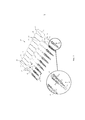
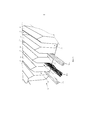
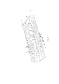
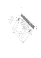
Фиг. 1 показывает в перспективе вид группы межзубных очистителей с увеличенным изображением участка очистки,FIG. 1 shows a perspective view of a group of interdental cleaners with an enlarged image of the cleaning site,
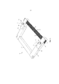
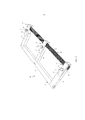
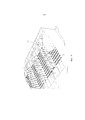
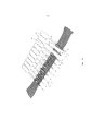
Фиг. 2 показывает в перспективе вид фиксирующей кассеты со вставленным полем филаментов,FIG. 2 shows in perspective a view of a fixing cassette with an inserted field of filaments,
Фиг. 3 показывает открытую, пустую фиксирующую кассету,FIG. 3 shows an open, empty fixation cassette,
Фиг. 4 показывает в перспективе вид открытого фиксирующего устройства фиксирующей кассеты,FIG. 4 shows in perspective a view of an open locking device of a fixing cassette,
Фиг. 5 показывает направляющую часть с несколькими различными вставленными пучками филаментов,FIG. 5 shows a guide part with several different filament bundles inserted,
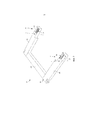
Фиг. 6 показывает в перспективе вид преобразованной формы исполнения фиксирующей кассеты,FIG. 6 shows in perspective a view of the converted form of the fixing cassette,
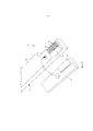
Фиг. 7 показывает в перспективе вид открытого устройства литья под давлением без фиксирующей кассеты,FIG. 7 shows a perspective view of an open injection molding device without a fixing cassette,
Фиг. 8 показывает в перспективе вид открытого устройства литья под давлением без фиксирующей кассеты со специальным исполнением первых позиционирующих частей,FIG. 8 shows in perspective a view of an open injection molding device without a fixing cassette with a special design of the first positioning parts,
Фиг. 9 показывает в перспективе увеличенный вид первой позиционирующей части,FIG. 9 shows in perspective an enlarged view of the first positioning part,
Фиг. 10 показывает первое альтернативное исполнение первой позиционирующей части,FIG. 10 shows the first alternative embodiment of the first positioning part,
Фиг. 11 показывает второе альтернативное исполнение первой позиционирующей части,FIG. 11 shows a second alternative embodiment of the first positioning part,
Фиг. 12 показывает устройство литья под давлением в соответствии с фиг. 7 с вложенной фиксирующей кассетой,FIG. 12 shows the injection molding device according to FIG. 7 with enclosed fixing cassette,
Фиг. 13 показывает в перспективе увеличенный вид первой позиционирующей части с вложенными пучками филамента перед закрыванием устройства литья под давлением,FIG. 13 shows in perspective an enlarged view of the first positioning part with nested filament bundles before closing the injection molding device,
Фиг. 14 показывает вид в соответствии с фиг. 13 после закрывания устройства литья под давлением,FIG. 14 shows the view of FIG. 13 after closing the injection molding device,
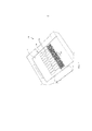
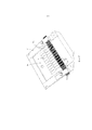
Фиг. 15 показывает в перспективе вид фиксирующей кассеты с опрыснутыми носителями,FIG. 15 shows a perspective view of a fixing cassette with sprinkled media,
Фиг. 16 показывает в перспективе вид полости для опрыскивания со вставленной фиксирующей кассетой и вторыми позиционирующими частями,FIG. 16 shows in perspective a view of a spray cavity with a fixing cassette inserted and second positioning parts,
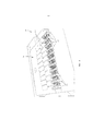
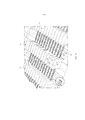
Фиг. 17 показывает в перспективе вид фиксирующей кассеты с опрыснутыми до готового состояния межзубными очистителями,FIG. 17 shows in perspective a view of a fixation cassette with interdental cleaners sprinkled to the finished state,
Фиг. 18 показывает фиксирующую кассету в соответствии с фиг. 13 в открытом положении, иFIG. 18 shows the locking cassette according to FIG. 13 in the open position, and
Фиг. 19 показывает схематическое изображение вырезки пучков филаментов.FIG. 19 shows a schematic representation of filament bundle cutting.
Осуществление изобретения The implementation of the invention
Фиг. 1 показывает группу 10 из расположенных рядом друг с другом межзубных очистителей 11, причем группа 10 в соответствии с фиг. 1 содержит в качестве примера десять межзубных очистителей 11. Каждый межзубный очиститель 11 состоит из полимерного материала и содержит носитель 12 в форме стержня, на заднем, правом в соответствии с фиг. 1 конце которого выполнен и сформован имеющий форму пластины участок 13 для захватывания. На переднем, аксиально противолежащем участку 13 для захватывания конце на носителе 12 в форме стержня расположен участок 14 очистки, который виден в увеличенном изображении на левой стороне фиг. 1. Участок 14 очистки содержит покрытие из мягко-упругого полимерного материала, который содержит на своей наружной стороне радиально выступающее структурирование в форме пальцев 17 или утолщений.FIG. 1 shows a group of 10
В материал носителя 12 в форме стержня внедрены щетины 15, которые свободным образом выступают в радиальном направлении на противолежащих сторонах в форме обрубков. In the material of the
Расположенные рядом друг с другом межзубные очистители 11 соединены на своих соответствующих участках 13 для захватывания обламываемыми, сформованными в качестве монолитного элемента перемычками 18, в результате чего образована имеющая форму полос взаимосвязанная группа 20 и пользователь может соответственно отделить один межзубный очиститель 11 путем обламывания соответствующей перемычки 18.The
В последующем описано, каким образом изготавливают изображенную на фиг. 1 группу 10 межзубных очистителей 11. Для этого предусмотрена фиксирующая кассета 20, которая изображен на фиг. с 2 по 5. Фиксирующая кассета 20 выполнена в качестве In the following, it is described how the apparatus shown in FIG. 1
U-образной рамы и содержит основание 23, а также два проходящих перпендикулярно к нему, свободно выступающих плеча 22. На внешних, обращенных от основания 23 концах плече 22 расположено соответственно фиксирующее устройство 24, с помощью которого можно позиционировать и фиксировать поле 25 филаментов, состоящее из нескольких, расположенных параллельно друг другу на расстоянии друг от друга пучков 32 филаментов. Как показывает фиг. 5, каждый пучок 32 филаментов может быть выполнен либо в виде пучка 32а из нескольких, проходящих параллельно друг другу прямых филаментов, либо в виде соответствующего, повернутого вокруг своей продольной оси пучка 32с, либо также расположенных рядом друг с другом не параллельно моноволокон в форме текстурированного пучка 32b.U-shaped frame and contains a
Как показывают, в частности, фиг. 3 и 4, каждое фиксирующее устройство 24 содержит направляющую часть 26, которая выполнена в форме гребня или грабель и содержит несколько расположенных рядом друг с другом направляющих ламелей 28, между которыми соответственно образован направляющий шлиц 27. В каждый направляющий шлиц 27 может быть вставлен пучок 32 филаментов, так что пучки 32 филаментов позиционированы заранее определенным образом и удерживаются на расстоянии. На соответственно другой стороне направляющей части 26, обращенной от соответственно другой направляющей части 26 на плече 22 рамы 21 выполнена зажимная поверхность 33, к которой прилегают выглядывающие из направляющей части 26 концевые участки пучков 32 филаментов. Зажимная поверхность 33 взаимодействует с фиксирующей планкой 30, которая содержит на своей нижней стороне выполненную предпочтительно в форме подушки зажимную часть 29, которая по своим размерам согласована с размерами зажимной поверхности 33. Фиксирующая планка 30 может быть наложена на плечо 22 рамы 21 и затянута с помощью зажимного устройства, например, в форме затяжного болта 31 таким образом, что пучки 32 филаментов прочно зажаты между зажимной поверхностью 33 и зажимной частью 29, как это показано на фиг. 2. Таким образом пучки 32 филаментов удерживают в их концевых областях с силовым замыканием и они свободно перекрывают с натяжением расстояние между плечами 22.As shown, in particular, FIG. 3 and 4, each locking
Фиг. 6 показывает преобразование фиксирующей кассеты 20 в соответствии с фиг. 2, причем рама 21 отныне выполнена с Е-образной формой, то есть содержит дополнительное среднее плечо 22, так что пучки 32 филаментов описанным образом с помощью позиционирующего устройства 24 позиционируют и удерживают посредством зажимания не только в их концевых областях, но и также в их центральной области.FIG. 6 shows the conversion of the fixing
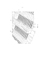
Фиг. 7 показывает открытое устройство 39 литья под давлением с частью 40 формы или половиной формы, в которой в соответствии с формой десяти расположенных рядом друг с другом межзубных очистителей 11 выполнена полость 41. Полость 41 содержит также десять участков 41а полости, которые служат соответственно для изготовления носителей 12 в форме стержня. В области переднего конца участков 41а полости между участками 41а полости и дополнительно сбоку рядом с соответственно наружными участками 41а полости соответственно расположены первые позиционирующие части 43. В то время как при исполнении в соответствии с фиг. 7 все первые позиционирующие части 43 имеют одинаковую высоту (измеренную в направлении введения и, следовательно, главным образом перпендикулярно плоскости чертежа в соответствии с фиг. 7), фиг. 8 показывает вариацию этого, причем некоторые из первых позиционирующих частей 43 имеют различную высоту. В случае изображенных примеров исполнения наиболее высокие первые позиционирующие части расположены соответственно в конце ряда, образованного первыми позиционирующими частями 43. Высота первых позиционирующих частей 43 уменьшается к середине ряда, причем в центре ряда расположена позиционирующая часть 43 с наименьшей высотой. Ступенчатость рядов первых позиционирующих частей 43 обуславливает, что пучки филаментов при вставлении фиксирующей кассеты в устройство литья под давлением вводят с временной задержкой поочередно в позиционирующие шлицы 44 первых позиционирующих частей 43, за счет чего снижается и даже предотвращается опасность ошибочного вставления пучков филаментов.FIG. 7 shows an open die-casting
Одна из первых позиционирующих частей 43 изображена на фиг. 9 в увеличенном масштабе. Каждая позиционирующая часть 43 выполнена в форме гребенки или граблей и содержит первые позиционирующие ламели 45, которые расположены на расстоянии друг от друга и образуют между собой соответственные первые позиционирующие шлицы 44, которые проходят перпендикулярно продольной протяженность участков 41а полости или носителя 12 в форме стержня. Ширина первых позиционирующих шлицев 44 обозначена на фиг. 8 ссылочным обозначением W.One of the
Непосредственно рядом с участками 41а полости для носителей 12 в форме стержня в части 40 формы выполнены углубления 46. Соответственно два углубления 46, выполненные на противоположных сторонах участка 41а полости, расположены на одной прямой и помимо этого выровнены с соседними первыми позиционирующими шлицами 44 первых позиционирующих частей 43. Ширина углублений 46, измеренная в продольном направлении участков 41а полости и параллельно ширине W первых позиционирующих шлицев 44, обозначена на фиг. 9 ссылочным обозначением В. При этом ширина В углублений 46 на 10%-30% больше ширины W первых позиционирующих шлицев.Directly next to the
Фиг. 10 показывает альтернативное исполнение первых позиционирующих частей 43, причем они хотя и опять выполнены в форме гребенки или граблей, они не содержат, однако, позиционирующих ламелей, а содержат два расположенных параллельно рядом друг с другом ряда однотипных, сужающихся конически под острым углом и расположенных на расстоянии первых позиционирующих штифтов 38. В соответствии с фиг. 11 предусмотрено следующее изменение, причем первые позиционирующие части 43 образованы соответственно лишь одним единственным рядом соответствующих, расположенных на расстоянии первых позиционирующих штифтов 38.FIG. 10 shows an alternative design of the
Загруженную полем 25 филаментов фиксирующая кассету 20 вставляют сверху в часть 40 формы устройства 39 литья под давлением. При этом пучки 32 филаментов заправляют соответственно в один из позиционирующих шлицев 44 каждой первой позиционирующей части 43 и, помимо этого, укладывают в углубления 46 части 40 формы. Это состояние показано на фиг. 13, причем видно, что пучки 32 филаментов на своем первоначально свободно напряженном участке между обоими фиксирующими устройствами 24 фиксирующей касты 20 отныне соответственно на обеих сторонах каждого участка 41а полости удерживают на расстоянии с помощью первых позиционирующих частей 43. Изображение данных на фиг. 13 показывает, что пучки 32 филаментов в этом состоянии выполнены многослойными из отдельных филаментов и также в области углублений 46 еще не полностью распределены на протяжении их ширины. Это происходит, если устройство 39 литья под давлением закрыто. Это состояние показано на фиг. 14, причем с целью повышения наглядности соответствующая часть формы устройства литья под давлением не изображена. При закрывании устройства литья под давлением на каждый пучок 32 филаментов перпендикулярно продольной протяженности филаментов воздействует сила сжатия, в результате чего происходит распределение филаментов в углублениях 46 и их прием углублениями 46 с узкой посадкой, а также с узкой набивкой. За счет этого обеспечивают не только точное позиционирование филаментов, но и дополнительно предотвращают возможность выхода впрыснутого на участки 41а полости полимерного материала в область углублений 46 или пучков 32 филаментов.Loaded with a field of 25 filaments, a locking
Поскольку ширина В углублений 46 больше ширины W первых позиционирующих шлицев, возникает показанная на фиг. 14 конфигурация, при которой каждый пучок 32 филаментов на том участке, который проходит внутри первого позиционирующего шлица 44, в незначительной мере сжат или сплющен и за счет этого выполнен выше, в то время, как он в области между двумя соседними позиционирующими частями 43 и, следовательно, в перекрывающей участки 41а полости области, расширяется в большей мере и применительно к своим размерам сформован более плоским за счет более широких углублений 46, как это изображено на фиг. 14.Since the width B of the
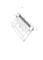
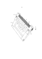
После вкладывания фиксирующей кассеты 20 с загруженными пучками 32 филаментов в устройство 39 литья под давлением последнее обычным образом закрывают и в полость 41 впрыскивают жидкий полимерный материал, который образует носитель 12 в форме стержня, участки 13 для захватывания и перемычки 18, соединяющие участки 13 для захватывания. Пучки 32 филаментов внедряются в полимерный материал носителей 12 в форме стержня и проникают, тем самым, через носители 12 в форме стержня. После открывания устройства 39 литья под давлением производят извлечение фиксирующей кассеты 20, в которой после этого на поле 25 филаментов сформованы десять межзубных очистителей 11, которые на своих участках 13 для захватывания соединены между собой с помощью перемычек 18. Это состояние показано на фиг. 15.After inserting the fixing
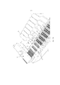
Если желательно произвести опрыскивание передних участков носителей 12 в форме стержня покрытием из мягко-упругого полимерного материала, например, термопластичного эластомера, нанесение соответствующих покрытий 16 путем опрыскивания на носители 12 в форме стержня производят на последующем технологическом этапе. Это может быть произведено либо в том же устройстве 39 литья под давлением, либо, однако, в другой или перемещенной части формы, либо в следующем устройстве 47 литья под давлением. В настоящем случае в качестве примера следует исходить из того, что предусмотрено следующее устройство 47 литья под давлением, как это показано на фиг. 16. Оно содержит полость 50 впрыска в соответствии с формой десяти подлежащих опрыскиванию покрытий 16. Дополнительно следующее устройство 47 литья подавлением содержит несколько вторых позиционирующих частей 48, которые соответствуют первым позиционирующим частям 43 устройства 39 литья под давлением и выполнены в форме гребенки или граблей, причем поле 25 филамента с десятью носителями 12 в форме стержня позиционируют в полости 50 впрыска таким образом, что каждый пучок 32 филаментов заправлен в соответственно образованный между вторыми позиционирующими ламелями 52 второй позиционирующий шлиц 49 вторых позиционирующих частей 48 и за счет этого позиционирован. Это состояние показано на фиг. 12.If it is desirable to spray the front sections of the
Конструктивная структура вторых позиционирующих частей 48 соответствует конструктивной структуре первых позиционирующих частей 43, на что следует указать во избежание повторений.The structural structure of the
После вставления фиксирующей кассеты 20 с полем 25 филаментов и укрепленными там носителями 12 в форме стержня в полость 50 впрыска или в следующее устройство 47 литья под давлением, последнее закрывают и производят впрыск мягко-упругого полимерного материала, который оснащает каждый из носителей 12 в форме стержня каждого межзубного очистителя 11 расположенным на передней стороне покрытием 16, которое содержит радиально расположенные с наружной стороны пальцы. После открывания следующего устройства 47 литья под давлением фиксирующую кассету 20 извлекают. Это состояние показано на фиг. 17. При этом все межзубные очистители 11 еще соединены между собой как перемычками 18 в области их участков 13 захватывания, так и пучками 32 филаментов в области их участков 14 очистки.After inserting the fixing
В завершение фиксирующие устройства 24, которые зажимают поле 25 филаментов в фиксирующей кассете 20, открывают (см. фиг. 18) и группу 10 из десяти межзубных очистителей 11 и поля 25 филаментов извлекают и подводят к секции резки, которая лишь обозначена на фиг. 19. В секции резки каждый носитель 12 в форме стержня вырезают из поля 25 филаментов с помощью двух проходящих на различных сторонах разрезов S1 и Finally, the
S2, которые сходятся в одной точке под острым углом в направлении переднего конца межзубного очистителя 11. Таким образом получают уже описанный во взаимосвязи с фиг. 1 участок 14 очистки межзубного очистителя 11 с комплектом щетин из выступающих на противоположны сторонах щетин 15 и покрытия 16 с радиально выступающими пальцами 17. Межзубные очистители 11 еще соединены между собой перемычками 18 и образуют показанную на фиг. 1 группу 10.S 2 , which converge at one point at an acute angle in the direction of the front end of the
Признаки изобретения, раскрытые в приведенном выше описании, пунктах формулы изобретения и чертежах, могут иметь значение для осуществления изобретения в его различных исполнениях как по отдельности, так и в любой комбинации.The features of the invention disclosed in the above description, the claims and the drawings may be relevant for carrying out the invention in its various versions, either individually or in any combination.
Claims (40)
Applications Claiming Priority (3)
| Application Number | Priority Date | Filing Date | Title |
|---|---|---|---|
| DE102014017257.0A DE102014017257A1 (en) | 2014-11-24 | 2014-11-24 | Method and device for producing an interdental cleaner |
| DE102014017257.0 | 2014-11-24 | ||
| PCT/EP2015/002299 WO2016082921A1 (en) | 2014-11-24 | 2015-11-18 | Method and device for producing an interdental cleaner |
Publications (3)
| Publication Number | Publication Date |
|---|---|
| RU2017121859A RU2017121859A (en) | 2018-12-26 |
| RU2017121859A3 RU2017121859A3 (en) | 2019-04-16 |
| RU2692457C2 true RU2692457C2 (en) | 2019-06-24 |
Family
ID=54703923
Family Applications (1)
| Application Number | Title | Priority Date | Filing Date |
|---|---|---|---|
| RU2017121859A RU2692457C2 (en) | 2014-11-24 | 2015-11-18 | Device and method for manufacturing of interdental cleaner |
Country Status (8)
| Country | Link |
|---|---|
| US (1) | US10843390B2 (en) |
| EP (1) | EP3223650B1 (en) |
| JP (1) | JP6837435B2 (en) |
| CN (1) | CN107105872B (en) |
| DE (1) | DE102014017257A1 (en) |
| ES (1) | ES2777773T3 (en) |
| RU (1) | RU2692457C2 (en) |
| WO (1) | WO2016082921A1 (en) |
Families Citing this family (10)
| Publication number | Priority date | Publication date | Assignee | Title |
|---|---|---|---|---|
| USD767900S1 (en) * | 2015-03-03 | 2016-10-04 | LeedTech Resources Company, LLC | Interdental brush |
| JP1603382S (en) | 2016-07-14 | 2018-05-07 | ||
| USD835417S1 (en) * | 2016-07-14 | 2018-12-11 | Sunstar Suisse S.A. | Interdental cleaner |
| JP6877136B2 (en) * | 2016-12-21 | 2021-05-26 | 日本製紙株式会社 | Manufacturing method of carboxylated cellulose nanofibers |
| CN108078152B (en) * | 2017-12-13 | 2024-02-13 | 倍加洁集团股份有限公司 | Interdental brush unit, connecting row and production method thereof |
| JP1661181S (en) * | 2019-09-27 | 2020-06-08 | ||
| JP1661179S (en) * | 2019-09-27 | 2020-06-08 | ||
| JP1661180S (en) * | 2019-09-27 | 2020-06-08 | ||
| DE102019133395A1 (en) * | 2019-12-06 | 2021-06-10 | Interbros Gmbh | Interdental cleaner |
| USD1021416S1 (en) * | 2021-03-02 | 2024-04-09 | Esro Ag | Interdental cleaner |
Citations (5)
| Publication number | Priority date | Publication date | Assignee | Title |
|---|---|---|---|---|
| JP2006212136A (en) * | 2005-02-02 | 2006-08-17 | Sunstar Inc | Interdentium cleaning instrument and its manufacturing method |
| DE102005008289A1 (en) * | 2005-02-23 | 2006-10-12 | Interbros Gmbh | Brushes are formed by locating bundles of bristles in a holder, forming heads on the bristles, and embedding the bristles in plastic |
| EP2100570A1 (en) * | 2008-03-12 | 2009-09-16 | Ranir LLC | Interdental cleaning tool |
| US20140008837A1 (en) * | 2013-09-09 | 2014-01-09 | Dennis Eatherton | Method of Manufacturing an Interdental Cleaner |
| WO2014023395A1 (en) * | 2012-08-09 | 2014-02-13 | Interbros Gmbh | Interdental cleaner |
Family Cites Families (16)
| Publication number | Priority date | Publication date | Assignee | Title |
|---|---|---|---|---|
| US2457440A (en) * | 1947-06-05 | 1948-12-28 | Herbert L Booth | Method for producing tufted plastic combs |
| US3843297A (en) * | 1971-03-24 | 1974-10-22 | R Espinosa | Apparatus for preparing measured lengths of dental floss |
| US4006750A (en) * | 1972-06-28 | 1977-02-08 | Placontrol Inc. | Disposable flosser |
| US3926201A (en) * | 1972-11-17 | 1975-12-16 | Harry Selig Katz | Method of making a disposable dental floss tooth pick |
| LU79138A1 (en) * | 1978-02-28 | 1979-09-06 | E Argembeau | BRUSHES MANUFACTURING PROCESS |
| SE463492B (en) * | 1986-04-21 | 1990-12-03 | Mats Ljungberg | SEE TO MAKE BRUSHED TOOTH |
| US5086792A (en) * | 1989-02-16 | 1992-02-11 | Placontrol Corp. | Dental floss loop devices, and methods of manufacture and packaging same |
| DE19642431A1 (en) | 1996-10-15 | 1998-04-16 | Coronet Werke Gmbh | Interdental cleaner and process for its manufacture |
| DE19956338C2 (en) * | 1999-11-23 | 2003-03-20 | Intier Automotive Eybl Interio | Device and method for producing clad moldings |
| US6544457B1 (en) * | 2000-02-17 | 2003-04-08 | Placontrol, Inc. | High speed injection molding apparatus and method for dental floss holder |
| JP4293978B2 (en) * | 2004-11-19 | 2009-07-08 | ライオン株式会社 | Method for manufacturing floss cleaning tool |
| EP2324796A1 (en) * | 2009-11-24 | 2011-05-25 | Niels Madsen Holding ApS | Dental interproximal cleaning device |
| EP3747616B1 (en) * | 2012-05-24 | 2023-03-22 | Sunstar Suisse SA | Interdental cleaning tool |
| EP2866610A1 (en) * | 2012-07-02 | 2015-05-06 | Trisa Holding AG | Method for producing brushes, in particular interdental brushes, and brush, in particular interdental brush, and product group comprising a plurality of brushes |
| DE102013010782A1 (en) * | 2013-06-28 | 2014-12-31 | Interbros Gmbh | Interdental cleaner and process for its preparation |
| DE102014011405A1 (en) * | 2014-08-06 | 2016-02-11 | Interbros Gmbh | Interdental cleaner and process for its preparation |
-
2014
- 2014-11-24 DE DE102014017257.0A patent/DE102014017257A1/en not_active Withdrawn
-
2015
- 2015-11-18 ES ES15800717T patent/ES2777773T3/en active Active
- 2015-11-18 WO PCT/EP2015/002299 patent/WO2016082921A1/en active Application Filing
- 2015-11-18 CN CN201580072757.4A patent/CN107105872B/en active Active
- 2015-11-18 EP EP15800717.9A patent/EP3223650B1/en active Active
- 2015-11-18 RU RU2017121859A patent/RU2692457C2/en active
- 2015-11-18 US US15/528,920 patent/US10843390B2/en active Active
- 2015-11-18 JP JP2017527752A patent/JP6837435B2/en active Active
Patent Citations (5)
| Publication number | Priority date | Publication date | Assignee | Title |
|---|---|---|---|---|
| JP2006212136A (en) * | 2005-02-02 | 2006-08-17 | Sunstar Inc | Interdentium cleaning instrument and its manufacturing method |
| DE102005008289A1 (en) * | 2005-02-23 | 2006-10-12 | Interbros Gmbh | Brushes are formed by locating bundles of bristles in a holder, forming heads on the bristles, and embedding the bristles in plastic |
| EP2100570A1 (en) * | 2008-03-12 | 2009-09-16 | Ranir LLC | Interdental cleaning tool |
| WO2014023395A1 (en) * | 2012-08-09 | 2014-02-13 | Interbros Gmbh | Interdental cleaner |
| US20140008837A1 (en) * | 2013-09-09 | 2014-01-09 | Dennis Eatherton | Method of Manufacturing an Interdental Cleaner |
Also Published As
| Publication number | Publication date |
|---|---|
| EP3223650B1 (en) | 2019-12-25 |
| JP6837435B2 (en) | 2021-03-03 |
| EP3223650A1 (en) | 2017-10-04 |
| RU2017121859A3 (en) | 2019-04-16 |
| WO2016082921A1 (en) | 2016-06-02 |
| US10843390B2 (en) | 2020-11-24 |
| DE102014017257A1 (en) | 2016-05-25 |
| RU2017121859A (en) | 2018-12-26 |
| US20170318948A1 (en) | 2017-11-09 |
| CN107105872A (en) | 2017-08-29 |
| CN107105872B (en) | 2020-07-03 |
| ES2777773T3 (en) | 2020-08-06 |
| JP2018500067A (en) | 2018-01-11 |
Similar Documents
| Publication | Publication Date | Title |
|---|---|---|
| RU2692457C2 (en) | Device and method for manufacturing of interdental cleaner | |
| US9968426B2 (en) | Method for the production of an interdental cleaner | |
| JP2018500067A5 (en) | ||
| DE60232828D1 (en) | SURGICAL DEVICE FOR REMOVING A FOREIGN BODY AND METHOD FOR THE PRODUCTION THEREOF | |
| EP2100570A1 (en) | Interdental cleaning tool | |
| US10687923B2 (en) | Interdental cleaner and method for manufacturing same | |
| WO2016147742A1 (en) | Optical connector cleaning tool | |
| US10398220B2 (en) | Tuft-picking device for a brush-making machine | |
| WO2016174263A1 (en) | Interdental cleaning device | |
| EP3138438B1 (en) | Tuft picker for a tuft picking device of a brush making machine | |
| US11089863B2 (en) | Tuft picker for a brush making machine | |
| JP4293978B2 (en) | Method for manufacturing floss cleaning tool | |
| WO2009106290A1 (en) | Comforter with a teat part fixed to a mouth shield | |
| KR101428757B1 (en) | Manufacturing method of disposable apparatus for dental flosser | |
| DE102015001650B4 (en) | Method and injection molding device for the production of injection molded plastic bodies | |
| EP3351143A1 (en) | Tuft picker for a brush making machine | |
| JPH09271481A (en) | Manufacture of floss cleaning instrument | |
| DE202005016771U1 (en) | Holding element for a sterilising material inside a basket chamber, comprises a base, fixing members, and a holder | |
| DE10345395A1 (en) | Semiconductor module and method for producing a semiconductor module | |
| KR20210014477A (en) | Dental Implant Cleaning Apparatus and Manufacturing Method Thereof | |
| WO2001091607A2 (en) | Clamp for retaining bristle bundles of various sizes | |
| RU98120895A (en) | INTRAVENOUS ANTI-EMBOLIC FILTER | |
| ITMI20090250A1 (en) | INTERDENTAL THREAD AND METHOD FOR ITS MANUFACTURE. | |
| JPS63294363A (en) | Freely detachable bundling jig | |
| ITBO20100673A1 (en) | TUBE CLADDING DEVICE. |