RU2689677C1 - Method and device for main and auxiliary air supply, in particular, rail vehicle - Google Patents
Method and device for main and auxiliary air supply, in particular, rail vehicle Download PDFInfo
- Publication number
- RU2689677C1 RU2689677C1 RU2018109581A RU2018109581A RU2689677C1 RU 2689677 C1 RU2689677 C1 RU 2689677C1 RU 2018109581 A RU2018109581 A RU 2018109581A RU 2018109581 A RU2018109581 A RU 2018109581A RU 2689677 C1 RU2689677 C1 RU 2689677C1
- Authority
- RU
- Russia
- Prior art keywords
- air tank
- compressor
- vehicle
- main
- switching valve
- Prior art date
Links
- 238000000034 method Methods 0.000 title claims abstract description 9
- 238000002360 preparation method Methods 0.000 claims abstract description 15
- 230000005611 electricity Effects 0.000 claims description 8
- 230000005540 biological transmission Effects 0.000 claims description 5
- 230000003213 activating effect Effects 0.000 claims 2
- 238000010248 power generation Methods 0.000 claims 2
- 239000000126 substance Substances 0.000 abstract 1
- 238000010586 diagram Methods 0.000 description 2
- 230000001105 regulatory effect Effects 0.000 description 2
- 238000010276 construction Methods 0.000 description 1
- 230000001419 dependent effect Effects 0.000 description 1
- 238000004146 energy storage Methods 0.000 description 1
- 230000007935 neutral effect Effects 0.000 description 1
- 238000005096 rolling process Methods 0.000 description 1
- 238000001179 sorption measurement Methods 0.000 description 1
- 230000007704 transition Effects 0.000 description 1
Images
Classifications
-
- B—PERFORMING OPERATIONS; TRANSPORTING
- B60—VEHICLES IN GENERAL
- B60L—PROPULSION OF ELECTRICALLY-PROPELLED VEHICLES; SUPPLYING ELECTRIC POWER FOR AUXILIARY EQUIPMENT OF ELECTRICALLY-PROPELLED VEHICLES; ELECTRODYNAMIC BRAKE SYSTEMS FOR VEHICLES IN GENERAL; MAGNETIC SUSPENSION OR LEVITATION FOR VEHICLES; MONITORING OPERATING VARIABLES OF ELECTRICALLY-PROPELLED VEHICLES; ELECTRIC SAFETY DEVICES FOR ELECTRICALLY-PROPELLED VEHICLES
- B60L5/00—Current collectors for power supply lines of electrically-propelled vehicles
- B60L5/18—Current collectors for power supply lines of electrically-propelled vehicles using bow-type collectors in contact with trolley wire
- B60L5/22—Supporting means for the contact bow
- B60L5/28—Devices for lifting and resetting the collector
- B60L5/32—Devices for lifting and resetting the collector using fluid pressure
-
- B—PERFORMING OPERATIONS; TRANSPORTING
- B60—VEHICLES IN GENERAL
- B60L—PROPULSION OF ELECTRICALLY-PROPELLED VEHICLES; SUPPLYING ELECTRIC POWER FOR AUXILIARY EQUIPMENT OF ELECTRICALLY-PROPELLED VEHICLES; ELECTRODYNAMIC BRAKE SYSTEMS FOR VEHICLES IN GENERAL; MAGNETIC SUSPENSION OR LEVITATION FOR VEHICLES; MONITORING OPERATING VARIABLES OF ELECTRICALLY-PROPELLED VEHICLES; ELECTRIC SAFETY DEVICES FOR ELECTRICALLY-PROPELLED VEHICLES
- B60L5/00—Current collectors for power supply lines of electrically-propelled vehicles
- B60L5/18—Current collectors for power supply lines of electrically-propelled vehicles using bow-type collectors in contact with trolley wire
- B60L5/22—Supporting means for the contact bow
- B60L5/24—Pantographs
-
- B—PERFORMING OPERATIONS; TRANSPORTING
- B60—VEHICLES IN GENERAL
- B60R—VEHICLES, VEHICLE FITTINGS, OR VEHICLE PARTS, NOT OTHERWISE PROVIDED FOR
- B60R16/00—Electric or fluid circuits specially adapted for vehicles and not otherwise provided for; Arrangement of elements of electric or fluid circuits specially adapted for vehicles and not otherwise provided for
- B60R16/08—Electric or fluid circuits specially adapted for vehicles and not otherwise provided for; Arrangement of elements of electric or fluid circuits specially adapted for vehicles and not otherwise provided for fluid
-
- B—PERFORMING OPERATIONS; TRANSPORTING
- B60—VEHICLES IN GENERAL
- B60T—VEHICLE BRAKE CONTROL SYSTEMS OR PARTS THEREOF; BRAKE CONTROL SYSTEMS OR PARTS THEREOF, IN GENERAL; ARRANGEMENT OF BRAKING ELEMENTS ON VEHICLES IN GENERAL; PORTABLE DEVICES FOR PREVENTING UNWANTED MOVEMENT OF VEHICLES; VEHICLE MODIFICATIONS TO FACILITATE COOLING OF BRAKES
- B60T17/00—Component parts, details, or accessories of power brake systems not covered by groups B60T8/00, B60T13/00 or B60T15/00, or presenting other characteristic features
- B60T17/18—Safety devices; Monitoring
- B60T17/22—Devices for monitoring or checking brake systems; Signal devices
- B60T17/228—Devices for monitoring or checking brake systems; Signal devices for railway vehicles
-
- B—PERFORMING OPERATIONS; TRANSPORTING
- B60—VEHICLES IN GENERAL
- B60L—PROPULSION OF ELECTRICALLY-PROPELLED VEHICLES; SUPPLYING ELECTRIC POWER FOR AUXILIARY EQUIPMENT OF ELECTRICALLY-PROPELLED VEHICLES; ELECTRODYNAMIC BRAKE SYSTEMS FOR VEHICLES IN GENERAL; MAGNETIC SUSPENSION OR LEVITATION FOR VEHICLES; MONITORING OPERATING VARIABLES OF ELECTRICALLY-PROPELLED VEHICLES; ELECTRIC SAFETY DEVICES FOR ELECTRICALLY-PROPELLED VEHICLES
- B60L1/00—Supplying electric power to auxiliary equipment of vehicles
- B60L1/003—Supplying electric power to auxiliary equipment of vehicles to auxiliary motors, e.g. for pumps, compressors
-
- B—PERFORMING OPERATIONS; TRANSPORTING
- B60—VEHICLES IN GENERAL
- B60T—VEHICLE BRAKE CONTROL SYSTEMS OR PARTS THEREOF; BRAKE CONTROL SYSTEMS OR PARTS THEREOF, IN GENERAL; ARRANGEMENT OF BRAKING ELEMENTS ON VEHICLES IN GENERAL; PORTABLE DEVICES FOR PREVENTING UNWANTED MOVEMENT OF VEHICLES; VEHICLE MODIFICATIONS TO FACILITATE COOLING OF BRAKES
- B60T17/00—Component parts, details, or accessories of power brake systems not covered by groups B60T8/00, B60T13/00 or B60T15/00, or presenting other characteristic features
- B60T17/02—Arrangements of pumps or compressors, or control devices therefor
-
- B—PERFORMING OPERATIONS; TRANSPORTING
- B60—VEHICLES IN GENERAL
- B60Y—INDEXING SCHEME RELATING TO ASPECTS CROSS-CUTTING VEHICLE TECHNOLOGY
- B60Y2200/00—Type of vehicle
- B60Y2200/30—Railway vehicles
- B60Y2200/33—Rail cars; Waggons
-
- B—PERFORMING OPERATIONS; TRANSPORTING
- B60—VEHICLES IN GENERAL
- B60Y—INDEXING SCHEME RELATING TO ASPECTS CROSS-CUTTING VEHICLE TECHNOLOGY
- B60Y2200/00—Type of vehicle
- B60Y2200/90—Vehicles comprising electric prime movers
- B60Y2200/91—Electric vehicles
- B60Y2200/912—Electric vehicles with power supply external to vehicle, e.g. trolley buses or trams
-
- B—PERFORMING OPERATIONS; TRANSPORTING
- B61—RAILWAYS
- B61C—LOCOMOTIVES; MOTOR RAILCARS
- B61C3/00—Electric locomotives or railcars
Landscapes
- Engineering & Computer Science (AREA)
- Mechanical Engineering (AREA)
- Transportation (AREA)
- Power Engineering (AREA)
- Physics & Mathematics (AREA)
- Fluid Mechanics (AREA)
- Compressors, Vaccum Pumps And Other Relevant Systems (AREA)
- Fluid-Pressure Circuits (AREA)
- Current-Collector Devices For Electrically Propelled Vehicles (AREA)
- Electric Propulsion And Braking For Vehicles (AREA)
- Vehicle Body Suspensions (AREA)
- Supply Devices, Intensifiers, Converters, And Telemotors (AREA)
Abstract
Description
Изобретение относится к способу и устройству для основного и вспомогательного воздухоснабжения транспортного средства с приводимым в действие посредством электродвигателя компрессором для выработки сжатого воздуха с целью заполнения, по меньшей мере, одного главного воздушного резервуара для снабжения пневматических агрегатов транспортного средства, причём транспортное средство снабжается электроэнергией от, по меньшей мере, одного первого и второго источника энергии и, причём пневматический исполнительный привод для подготовки к работе транспортного средства и для активирования первого источника энергии приводится в действие посредством выработанного компрессором сжатого воздуха за счёт того, что электродвигатель компрессора на этом этапе питается от второго источника энергии.The invention relates to a method and apparatus for main and auxiliary air supply of a vehicle with a compressor driven by an electric motor for generating compressed air to fill at least one main air reservoir for supplying pneumatic components of a vehicle, and the vehicle is supplied with electricity from, at least one first and second energy source and, moreover, a pneumatic actuator to prepare to the operation of the vehicle and to activate the first energy source is driven by compressed air produced by the compressor due to the fact that the compressor electric motor at this stage is powered from the second energy source.
Область применения изобретения распространяется преимущественно на сферу строительства железнодорожного подвижного состава, а именно, рельсовых транспортных средств с электроприводом, которые, к примеру, посредством пантографа подают необходимую для работы электроэнергию от воздушной линии. Наряду с этим первым источником энергии рассматриваемые в данном случае транспортные средства имеют также второй источник энергии, к примеру, в форме аккумуляторной батареи транспортного средства для аккумулирования электроэнергии, которая предусмотрена для снабжения электрических вспомогательных агрегатов, в случае, если первый источник электроэнергии не находится в распоряжении. Выработанный компрессором сжатый воздух используется преимущественно для снабжения пневматических агрегатов, к примеру, тормозной системы транспортного средства. Возможно также использование предложенного на рассмотрение изобретения на безрельсовых транспортных средствах, к примеру, на троллейбусах и т.д. The scope of the invention extends mainly to the construction of railway rolling stock, namely, electric rail vehicles, which, for example, by means of a pantograph, supply the necessary electric energy from an overhead line. Along with this, the vehicles considered in this case also have a second energy source as a second energy source, for example, in the form of a vehicle battery for energy storage, which is provided for supplying electrical accessories, in case the first power source is not available . The compressed air developed by the compressor is used mainly for supplying pneumatic units, for example, the braking system of a vehicle. It is also possible to use the proposed invention for consideration on trackless vehicles, for example, on trolleybuses, etc.
В соответствии с общеизвестным уровнем техники для вспомогательного воздухоснабжения, наряду с главным компрессором, обычно используется так называемый вспомогательный воздушный компрессор, который вырабатывает пневматическую энергию для исполнительного привода пантографа и проч. Такой отдельный вспомогательный воздушный компрессор посредством аккумуляторной батареи рельсового транспортного средства снабжается электроэнергией и имеет, по сравнению с главным компрессором, сравнительно небольшую мощность. Электроэнергии аккумуляторной батареи транспортного средства при этом достаточно для приведения в действие вспомогательного воздушного компрессора посредством электродвигателя, так что может быть получено достаточное количество сжатого воздуха для вспомогательного воздухоснабжения. In accordance with the well-known prior art for auxiliary air supply, along with the main compressor, the so-called auxiliary air compressor is usually used, which generates pneumatic energy for the executive drive of the pantograph and so on. Such a separate auxiliary air compressor is supplied with electricity and has a relatively small capacity compared to the main compressor by means of a rail vehicle battery. The electric power of the vehicle battery is sufficient to activate the auxiliary air compressor by means of an electric motor, so that a sufficient amount of compressed air can be obtained for the auxiliary air supply.
Из документа DE 10 2013 109 475 А1 следует техническое решение, при котором такой отдельный вспомогательный воздушный компрессор является излишним, так как его функцию берёт на себя главный компрессор транспортного средства. Для вспомогательного воздухоснабжения при подготовке к работе транспортного средства посредством главного компрессора его приводной электродвигатель через преобразователь частоты приводится в действие посредством подаваемой от аккумуляторной батареи электроэнергии. Полученной таким образом пусковой энергии достаточно для приведения в действие главного компрессора с относительно небольшой частотой вращения и для отведения сжатого воздуха для вспомогательного воздухоснабжения от обводной линии напорного трубопровода для сжатого воздуха. Вспомогательное отведение воздуха осуществляется сзади подключённого за главным компрессором блока осушителя воздуха. Для предотвращения обратного выхода сжатого воздуха из главного воздушного резервуара, его выходное отверстие снабжается обратным клапаном. Другие клапанные средства для отведения сжатого воздуха для вспомогательного воздушного резервуара не предусмотрены. From the
Задачей предложенного на рассмотрение изобретения является дальнейшее усовершенствование способа, а также устройства для основного и вспомогательного воздухоснабжения по типу в соответствии с оригинальной версией, таким образом, чтобы посредством простых технических средств можно было обеспечить управляемое отведение вспомогательного воздуха для подготовки к работе транспортного средства.The objective of the proposed invention is a further improvement of the method, as well as devices for main and auxiliary air supply of the type in accordance with the original version, so that using simple technical means it is possible to provide controlled discharge of auxiliary air to prepare the vehicle.
Задача с точки зрения способа решается посредством пункта 1 формулы изобретения. В отношении соответствующего устройства для основного и вспомогательного воздухоснабжения задача решена посредством пункта 5 формулы изобретения. Соответствующие зависимые пункты формулы изобретения выявляют предпочтительные варианты осуществления изобретения.The task from the point of view of the method is solved by paragraph 1 of the claims. With regard to the corresponding device for the main and auxiliary air supply, the problem is solved by means of clause 5 of the claims. The respective dependent claims identify preferred embodiments of the invention.
Изобретение заключает в себе техническую идею о том, что сжатый воздух для подготовки к работе транспортного средства от предпочтительно приводимого в действие от аккумуляторной батареи посредством второго источника энергии (главного) компрессора посредством устройства клапана переключения подаётся на присоединённый к пневматическому исполнительному приводу пантографа или основного переключателя вспомогательный воздушный резервуар. В противном случае, то есть, после произведённой подготовки к работе и активирования первого источника энергии, выработанный компрессором сжатый воздух посредством устройства клапана переключения подаётся к главному воздушному резервуару.The invention encompasses the technical idea that compressed air for preparing the vehicle for operation from preferably powered by the battery through the second energy source of the (main) compressor through the switching valve device is supplied to the auxiliary pantograph or main switch connected to the pneumatic actuator air reservoir. Otherwise, that is, after the preparatory work has been completed and the first energy source is activated, the compressed air produced by the compressor is supplied to the main air reservoir via a switching valve device.
Преимущество решения в соответствии с изобретением состоит, в частности, в том, что подготовка к работе транспортного средства, то есть, переход в режим эксплуатационной готовности, посредством подсоединения, к примеру, пантографа к воздушной линии электропередачи, может быть осуществлён и с пустым в исходном состоянии главным воздушным резервуаром и вспомогательным воздушным резервуаром, без отдельного вспомогательного компрессора. За счёт того, что электродвигатель компрессора питается, к примеру, от аккумуляторной батареи транспортного средства в качестве второго источника энергии, компрессор с достаточной мощностью сначала с управлением от клапана может заполнить вспомогательный воздушный резервуар сжатым воздухом для работы пневматического исполнительного привода пантографа, чтобы, таким образом, отвести пантограф. Если затем первый источник энергии посредством пантографа оказывается подсоединённым, то компрессор может эксплуатироваться с нормальной мощностью и выработанный, таким образом, сжатый воздух посредством устройства клапана переключения подаётся к главному воздушному резервуару и на предпочтительно присоединённую к нему линию. Устройство клапана переключения в соответствии с изобретением позволяет осуществить, таким образом, необходимую подачу сжатого воздуха, в частности, на этапе подготовки к работе транспортного средства.The advantage of the solution in accordance with the invention is, in particular, that the preparation for the operation of the vehicle, that is, the transition to the operational readiness mode, by connecting, for example, a pantograph to an overhead transmission line, can also be carried out with an empty state of the main air tank and auxiliary air tank, without a separate auxiliary compressor. Due to the fact that the compressor electric motor is powered, for example, from a vehicle battery as a second energy source, a compressor with sufficient power, first controlled by a valve, can fill the auxiliary air tank with compressed air to operate the pneumatic actuator of the pantograph so that , take the pantograph. If then the first energy source is connected by means of a pantograph, the compressor can be operated with normal power and the compressed air generated in this way is supplied to the main air reservoir via a switching valve device and preferably to a line connected to it. The switching valve device according to the invention thus makes it possible to supply the compressed air, in particular, at the stage of preparation for the operation of the vehicle.
В нормальном режиме работы транспортного средства, то есть, не в период подготовке к работе, устройство клапана переключения также может быть таким образом активировано посредством давления во вспомогательном воздушном резервуаре, что при снижении значения давления ниже минимального во вспомогательном воздушном резервуаре, он снова заполняется сжатым воздухом. Когда достигается заданный уровень давления во вспомогательном воздушном резервуаре, устройство клапана переключения может быть снова переключено, так что снова главный воздушный резервуар может быть при необходимости заполнен выработанным компрессором сжатым воздухом. Эта мера гарантирует то, что вспомогательный воздушный резервуар будет заполняться сжатым воздухом в первую очередь, по сравнению с главным воздушным резервуаром. Значение давления переключения устройства клапана переключения в предпочтительном варианте ниже номинального значения давления подачи главного воздушного резервуара. При номинальном значении давления подачи от 8,5 до 10 бар значение давления переключения может составлять, к примеру, 7,5 бар.In normal operation of the vehicle, that is, not during preparation for operation, the switching valve device can also be activated by means of pressure in the auxiliary air tank, so that when the pressure drops below the minimum in the auxiliary air tank, it is filled again with compressed air . When the preset pressure level in the auxiliary air tank is reached, the switching valve device can be switched again, so that the main air tank can again be filled with compressed air developed by the compressor if necessary. This measure ensures that the auxiliary air tank will be filled with compressed air in the first place, compared to the main air tank. The switching pressure of the switching valve device is preferably below the nominal supply pressure of the main air tank. With a nominal supply pressure of 8.5 to 10 bar, the switching pressure value can be, for example, 7.5 bar.
В альтернативном варианте или в дополнение к этому предлагается осуществлять заполнение вспомогательного воздушного резервуара сжатым воздухом главного воздушного резервуара, в случае, если он обеспечен достаточным запасом сжатого воздуха. Для этого легко может быть предусмотрен подключённый параллельно устройству клапана переключения клапанный элемент, который может являться также составной частью устройства клапана переключения. Параллельно подключённый клапанный элемент соединяет в обход устройства клапана переключения главный воздушный резервуар со вспомогательным воздушным резервуаром. В самом простом случае клапанный элемент может быть осуществлён в виде упруго нагружаемого обратного клапана с направлением пропускания от главного воздушного резервуара к вспомогательному воздушному резервуару. Посредством упругого усилия обратного клапана может регулироваться давление переключения. В соответствии с альтернативным вариантом осуществления, однако, возможно также вместо обратного клапана использовать другой механический, пневматический, гидравлический или электрический клапан.Alternatively, or in addition, it is proposed to fill the auxiliary air tank with compressed air from the main air tank, if it is provided with an adequate supply of compressed air. For this purpose, a valve element connected in parallel with the switching valve device can be provided, which can also be part of the switching valve device. A parallel-connected valve element bypasses the switching valve device bypassing the main air tank with the auxiliary air tank. In the simplest case, the valve element can be implemented in the form of a resiliently loaded check valve with the direction of transmission from the main air tank to the auxiliary air tank. By means of the elastic force of the non-return valve, the switching pressure can be adjusted. In accordance with an alternative embodiment, however, it is also possible to use another mechanical, pneumatic, hydraulic or electric valve instead of a non-return valve.
Устройство клапана переключения в соответствии с предметом изобретения в предпочтительном варианте имеет электропривод, причём блок управления в данном случае задаёт электрический сигнал управления. Устройство клапана переключения в соответствии с изобретением также может иметь вместо этого механическую, пневматическую или гидравлическую систему управления. В этом случае, к примеру, возможно также чисто механически реализовать устройство клапана переключения посредством перепускного клапана, а датчики давления посредством переключателей давления. В этом случае блок управления, в частности, электронный блок управления, также может отсутствовать. The switching valve device in accordance with the subject matter of the invention preferably has an electric drive, and in this case the control unit sets an electrical control signal. The switching valve device according to the invention may also have a mechanical, pneumatic or hydraulic control system instead. In this case, for example, it is also possible to purely mechanically implement a switching valve device by means of an overflow valve, and pressure sensors by means of pressure switches. In this case, the control unit, in particular, the electronic control unit, may also be missing.
У устройства клапана переключения с электроприводом блок управления осуществлён в виде электронного блока управления, который со стороны входа электрически соединён с датчиком давления на главном воздушном резервуаре, а также с датчиком давления на вспомогательном воздушном резервуаре. Вместо датчиков давления возможно также использовать двоично переключаемые датчики давления. Для этого электронный блок управления всегда обладает фактической информацией о преобладающем уровне давления в обоих резервуарах и может, в зависимости от приоритетов, регулировать снабжение сжатым воздухом вспомогательного воздушного резервуара и главного воздушного резервуара, а электронный блок управления выдаёт соответствующий сигнал переключения для устройства клапана переключения с электроприводом. Наряду с этим, посредством электронного блока управления может осуществляться также управление электродвигателем компрессора.At the device of the switching valve with electric drive, the control unit is implemented in the form of an electronic control unit, which is electrically connected from the input side to the pressure sensor on the main air tank, as well as to the pressure sensor on the secondary air tank. Instead of pressure sensors it is also possible to use binary switchable pressure sensors. To do this, the electronic control unit always has actual information about the prevailing pressure level in both tanks and, depending on priorities, can regulate the supply of compressed air to the auxiliary air tank and the main air tank, and the electronic control unit generates the appropriate switching signal for the electric switching valve device . In addition, the compressor motor can also be controlled by the electronic control unit.
В предпочтительном варианте мощность компрессора может регулироваться посредством подключённого перед электродвигателем преобразователя за счёт изменения напряжения и/или частоты. Это изменение может осуществляться либо плавно, либо ступенчато. В альтернативном варианте мощность компрессора может изменяться также за счёт электрического, пневматического, гидравлического или механического приведения в действие клапанного устройства, к примеру, устройства для отведения воздуха, на компрессоре, к примеру, в диапазоне от высокого давления до низкого давления многоступенчатого, в этом случае, поршневого компрессора. In the preferred embodiment, the compressor power can be regulated by means of a converter connected in front of the electric motor due to a change in voltage and / or frequency. This change can be done either smoothly or in steps. Alternatively, the compressor power can also be changed by electrically, pneumatically, hydraulically or mechanically actuating the valve device, for example, the air exhaust device, at the compressor, for example, in the range from high pressure to low pressure multi-stage, in this case , piston compressor.
Устройство клапана переключения в соответствии с изобретением может быть осуществлено в соответствии с первым предпочтительным вариантом осуществления в виде ходового клапана 3/2, который в первом положении переключения генерированное компрессором давление питания подаёт к вспомогательному воздушному резервуару, а во втором положении переключения подаёт генерированное компрессором давление питания к главному воздушному резервуару.The switching valve device according to the invention can be implemented in accordance with the first preferred embodiment as a 3/2 directional valve, which in the first switching position supplies the supply pressure generated by the compressor to the auxiliary air tank, and in the second switching position supplies the pressure generated by the compressor to the main air reservoir.
В соответствии со вторым предпочтительным вариантом осуществления устройство клапана переключения может быть осуществлено в виде ходового клапана 2/2, который в открытом положении переключения подаёт генерированное компрессором давление питания к главному воздушному резервуару, а в закрытом положении переключения блокирует это соединение, причём в дополнение к этому имеет место перманентная подача сжатого воздуха в направлении от компрессора к вспомогательному воздушному резервуару. При таком варианте осуществления заполнение вспомогательного воздушного резервуара сжатым воздухом является приоритетным, без необходимости активирования для этого устройства клапана переключения.According to the second preferred embodiment, the switching valve device can be implemented as a 2/2 directional valve, which in the open switching position supplies the pressure generated by the compressor to the main air tank, and in the closed switching position blocks this connection, and in addition to this There is a permanent supply of compressed air in the direction from the compressor to the auxiliary air tank. In this embodiment, the filling of the auxiliary air tank with compressed air is a priority, without the need to activate the switching valve for this device.
Следует указать на то, что за компрессором для снабжения сжатым воздухом обычно подсоединён блок осушителя воздуха, который в достаточной степени осушает выработанный компрессором из окружающего воздуха сжатый воздух, без необходимости использования дополнительной системы для сжатого воздуха. Блок осушителя воздуха может быть осуществлён, к примеру, в виде адсорбционного осушителя. It should be noted that an air dryer unit is usually connected behind the compressor to supply compressed air, which sufficiently drains the compressed air produced by the compressor from the surrounding air, without the need for an additional system for compressed air. The air dryer unit can be implemented, for example, as an adsorption dryer.
Далее следует указать на то, что из вспомогательного воздушного резервуара при подготовке к работе сжатый воздух подаётся не только на исполнительный привод пантографа, но и в дополнение к этому – если необходимо – к примеру, также на уже известный главный переключатель с пневматическим приводом, для переключения подачи тока к транспортному средству.Further, it should be noted that, in preparation for operation, compressed air is supplied not only to the executive drive of the pantograph, but also in addition to this — if necessary — for example, also to the already known main pneumatic actuator switch to switch supply current to the vehicle.
Другие улучшающие изобретение мероприятия представляются далее более детально в описании предпочтительных вариантов осуществления изобретения на основании чертежей, на которых представлено следующее:Other measures improving the invention are further described in more detail in the description of the preferred embodiments of the invention based on the drawings, which present the following:
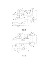
фиг.1 - схематичное изображение в виде блок-схемы устройства для основного и вспомогательного воздухоснабжения для рельсового транспортного средства с устройством клапана переключения в соответствии с первым вариантом осуществления, иFIG. 1 is a schematic block diagram of a device for main and auxiliary air supply for a rail vehicle with a switching valve device in accordance with the first embodiment, and
фиг.2 - схематичное изображение в виде блок-схемы устройства для основного и вспомогательного воздухоснабжения для рельсового транспортного средства с устройством клапана переключения в соответствии со вторым вариантом осуществления.FIG. 2 is a schematic block diagram of a device for main and auxiliary air supply for a rail vehicle with a switching valve device in accordance with a second embodiment. FIG.
В соответствии с фиг.1 в рамках системы основного и вспомогательного воздухоснабжения – не представленного далее – рельсового транспортного средства предусмотрен компрессор 1 для выработки сжатого воздуха для заполнения главного воздушного резервуара 3, а также соединённого с ним воздухопровода 4 главного воздушного резервуара. Компрессор 1 приводится в действие посредством электродвигателя 2. Электроэнергия для приведения в действие электродвигателя 2 первично получается через пантограф 5 посредством соединения с воздушной линией. Вторым вариантом энергоснабжения служит аккумуляторная батарея 6 транспортного средства. Энергоснабжение посредством пантографа 5 и аккумуляторной батареи 6 транспортного средства регулируется электронным блоком 7 управления, который также имеет встроенный преобразователь 8 для изменения напряжения и частоты, с целью приведения в действие электродвигателя 2. Электродвигатель 2 осуществлён в данном случае в виде трёхфазного электродвигателя. In accordance with FIG. 1, a compressor 1 is provided within the framework of the main and auxiliary air supply system of a rail vehicle that is not presented below for generating compressed air to fill the
Соединённый с пантографом 5 пневматический исполнительный привод 9 приводится в действие для подведения и отведения пантографа 5 с выработанным компрессором 1 сжатым воздухом. The pneumatic actuator 9 connected to the pantograph 5 is actuated to sum up and discharge the pantograph 5 with the compressed air developed by the compressor 1.
Так как на этапе подготовки к работе транспортного средства, когда пантограф 5 ещё находится в подведённом нейтральном положении, отсутствует подача электроэнергии от воздушной линии, электродвигатель 2 компрессора 1 сначала снабжается электроэнергией от аккумуляторной батареи 6 транспортного средства. Электроэнергии, которая может быть подана от аккумуляторной батареи 6 транспортного средства, на этом этапе достаточно для подготовки к работе транспортного средства, с целью приведения в действие компрессора 1 с небольшой мощностью, которой достаточно для активирования пневматического исполнительного привода 9 с целью отведения пантографа 5. Since at the stage of preparation for the operation of the vehicle, when the pantograph 5 is still in the neutral position, there is no power supply from the overhead line, the electric motor 2 of the compressor 1 is first supplied with electric power from the vehicle battery 6. Electricity, which can be supplied from the vehicle battery 6, is sufficient at this stage to prepare the vehicle for operation, in order to activate the compressor 1 with a small capacity, which is sufficient to activate the pneumatic actuator 9 to retract the pantograph 5.
Для этой цели выработанный приводимым в действие от аккумуляторной батареи компрессором 1 сжатый воздух посредством устройства 10 клапана переключения, которое в данном случае осуществлено в виде электропневматического ходового клапана 3/2, посредством электрического блока 7 управления подаётся к вспомогательному воздушному резервуару 11, который пополняет запасы сжатого воздуха для работы пневматического исполнительного привода 9 пантографа 5. Вне этапа подготовки к работе транспортного средства устройство 10 клапана переключения подаёт выработанный компрессором 1 сжатый воздух к главному воздушному резервуару 3 транспортного средства. Заполнение главного воздушного резервуара 3 транспортного средства осуществляется в предпочтительном варианте при первоначальном электрическом энергоснабжении от пантографа 5.For this purpose, the compressed air produced by the compressor 1 driven by the battery 1 is switched by means of the switching
Если к моменту подготовки к работе транспортного средства в главном воздушном резервуаре 3 имеется ещё достаточное количество сжатого воздуха, от 8,5 бар до 10 бар, то может быть осуществлено также заполнение пустого вспомогательного воздушного резервуара 11. Для этой цели имеется подключённый параллельно к устройству 10 клапана переключения клапанный элемент 12 в форме обратного клапана с направлением пропускания от главного воздушного резервуара 3 к вспомогательному воздушному резервуару 11.If at the time of preparation for the operation of the vehicle in the
В данном примере осуществления изобретения устройство 10 клапана переключения управляется от электропривода и электронный блок 7 управления задаёт для этого электрический сигнал управления (пунктирна линия). На электронный блок 7 управления со стороны входа сигнала подаётся сигнал давления с первого датчика 13 давления на главном воздушном резервуаре 3, а также со второго датчика 14 давления на вспомогательном воздушном резервуаре 11 (пунктирные линии). На основании этого электронный блок 7 управления определяет в соответствии с ранее описанной логической схемой сигнал переключения для устройства 10 клапана переключения с электроприводом, а также компрессора 1. In this embodiment of the invention, the switching
В отношении осуществлённого в виде ходового клапана 3/2 устройства 10 клапана переключения в первом положении переключения генерированное компрессором 1 давление питания подаётся к вспомогательному воздушному резервуару 11 – в частности, на этапе подготовки к работе – а во втором положении переключения генерированное компрессором 1 давление питания подаётся к главному воздушному резервуару 3, для обеспечения главной системы воздухоснабжения. In relation to the switching
В соответствии с проиллюстрированным на фиг.2 альтернативным вариантом осуществления устройство 10´ клапана переключения осуществлено в виде ходового клапана 2/2. В открытом положении переключения он подаёт генерированное компрессором 1 давление питания к главному воздушному резервуару 3. В закрытом положении переключения устройство 10´ клапана переключения блокирует это соединение. Кроме того, имеет место перманентная передача сжатого воздуха от компрессора 1 к вспомогательному воздушному резервуару 11, на которую, в связи с этим, не оказывает влияния положение переключения устройства 10´ клапана переключения. Благодаря этому, достигается первичная подача сжатого воздуха к вспомогательному воздушному резервуару 11, без приведения в действие клапана.In accordance with the alternative embodiment illustrated in FIG. 2, the switching
Изобретение не ограничено двумя ранее описанными предпочтительными примерами осуществления. Более того, возможны также их варианты в пределах объёма правовой защиты последующей формулы изобретения. Так, к примеру, возможно также осуществить устройство клапана переключения в виде пневматического, гидравлического или механического клапана управления, а управление осуществлять посредством соответствующей подходящей управляющей среды. Наряду с этим могут найти применение, к примеру, также, вместо электрических датчиков давления, механические сигнализаторы изменений давления или нечто подобное, для контроля уровня давления в главном воздушном резервуаре 3, а также во вспомогательном воздушном резервуаре 11. Подсоединённый параллельно устройству 10 или 10´ клапана переключения клапанный элемент может быть осуществлён далее также в виде активно управляемого клапана или нечто подобного. В отношении варианта осуществления компрессора с соединёнными с ним системой подготовки сжатого воздуха и устройством удаления воздуха или без них в рамках объёма правовой защиты также отсутствуют ограничения. The invention is not limited to the two previously described preferred embodiments. Moreover, their variants are also possible within the scope of the legal protection of the subsequent claims. So, for example, it is also possible to carry out the switching valve device in the form of a pneumatic, hydraulic or mechanical control valve, and to control it by means of a corresponding appropriate control medium. Along with this, for example, instead of electric pressure sensors, mechanical alarms for pressure changes or something similar can also be used to monitor the pressure level in the
Claims (36)
Applications Claiming Priority (3)
| Application Number | Priority Date | Filing Date | Title |
|---|---|---|---|
| DE102015113940.5A DE102015113940A1 (en) | 2015-08-21 | 2015-08-21 | Method and device for main and auxiliary air supply, in particular a rail vehicle |
| DE102015113940.5 | 2015-08-21 | ||
| PCT/EP2016/069199 WO2017032616A1 (en) | 2015-08-21 | 2016-08-12 | Method and device for supplying, in particular a rail vehicle, with main and auxiliary air |
Publications (1)
| Publication Number | Publication Date |
|---|---|
| RU2689677C1 true RU2689677C1 (en) | 2019-05-28 |
Family
ID=56800269
Family Applications (1)
| Application Number | Title | Priority Date | Filing Date |
|---|---|---|---|
| RU2018109581A RU2689677C1 (en) | 2015-08-21 | 2016-08-12 | Method and device for main and auxiliary air supply, in particular, rail vehicle |
Country Status (8)
| Country | Link |
|---|---|
| US (1) | US11130408B2 (en) |
| EP (1) | EP3337685B1 (en) |
| JP (1) | JP6820317B2 (en) |
| KR (1) | KR102600362B1 (en) |
| CN (1) | CN108025650B (en) |
| DE (1) | DE102015113940A1 (en) |
| RU (1) | RU2689677C1 (en) |
| WO (1) | WO2017032616A1 (en) |
Families Citing this family (3)
| Publication number | Priority date | Publication date | Assignee | Title |
|---|---|---|---|---|
| DE102017107276A1 (en) * | 2017-04-05 | 2018-10-11 | Knorr-Bremse Systeme für Schienenfahrzeuge GmbH | Method and device for a demand-based compressed air supply of a vehicle, in particular a rail vehicle |
| DE102017214111A1 (en) * | 2017-08-11 | 2019-02-14 | Knorr-Bremse Systeme für Schienenfahrzeuge GmbH | Electropneumatically controlled control of a pantograph |
| JP7220561B2 (en) * | 2018-12-26 | 2023-02-10 | ナブテスコ株式会社 | Air compression system for railway vehicles |
Citations (5)
| Publication number | Priority date | Publication date | Assignee | Title |
|---|---|---|---|---|
| RU2100220C1 (en) * | 1996-12-25 | 1997-12-27 | Акционерное общество закрытого типа "Спецремонт" | Pantograph control device |
| DE102008056479A1 (en) * | 2008-11-05 | 2010-05-06 | Siemens Aktiengesellschaft | Compressed air system with a pressure vessel and method for operating the compressed air system |
| DE102010008636A1 (en) * | 2010-02-18 | 2011-08-18 | Siemens Aktiengesellschaft, 80333 | Device for providing a supply pressure |
| RU130273U1 (en) * | 2013-02-28 | 2013-07-20 | Открытое Акционерное Общество "Российские Железные Дороги" | ELECTRIC PNEUMATIC BRAKE SYSTEM |
| DE102013109475A1 (en) * | 2013-08-30 | 2015-03-05 | Knorr-Bremse Systeme für Schienenfahrzeuge GmbH | Method and device for auxiliary air supply of a rail vehicle |
Family Cites Families (12)
| Publication number | Priority date | Publication date | Assignee | Title |
|---|---|---|---|---|
| JPS59176301U (en) | 1983-05-13 | 1984-11-26 | 株式会社日立製作所 | Vehicle battery control device |
| JPS6132701U (en) | 1984-07-27 | 1986-02-27 | 株式会社日立製作所 | Pneumatic vehicle pantograph elevation control device |
| JPS62126802A (en) * | 1985-11-27 | 1987-06-09 | Hitachi Ltd | Controller for current collector of rolling stock |
| DE3613069A1 (en) * | 1986-04-18 | 1987-10-29 | Knorr Bremse Ag | Compressor system, in particular for traction units in the field of rail vehicles |
| JPH059101U (en) | 1991-07-08 | 1993-02-05 | 株式会社日立製作所 | Railway vehicle current collector control system |
| JP2004019625A (en) | 2002-06-20 | 2004-01-22 | Matsushita Electric Ind Co Ltd | Wind power using air system |
| DE10336058B3 (en) | 2003-08-01 | 2005-01-05 | Siemens Ag | Supply pressure provision device e.g. for pneumatic control for electrified rail vehicle current take-off, has main air system containing compressor and auxiliary air system with pressurized gas flask |
| DE102006057065A1 (en) | 2006-11-29 | 2008-06-05 | Siemens Ag | Method for braking a rail vehicle |
| CN201863864U (en) | 2010-11-25 | 2011-06-15 | 南车资阳机车有限公司 | Air brake system for railcars |
| CN102431458B (en) * | 2011-11-29 | 2013-12-04 | 南车株洲电力机车有限公司 | Pantograph control device and pantograph control method |
| KR101434311B1 (en) | 2013-02-19 | 2014-08-27 | 현대로템 주식회사 | Air compressor starting delay circuit of railway vehicles and the railway vehicles |
| DE102013217429A1 (en) * | 2013-09-02 | 2015-03-05 | Siemens Aktiengesellschaft | Compressed air system |
-
2015
- 2015-08-21 DE DE102015113940.5A patent/DE102015113940A1/en not_active Ceased
-
2016
- 2016-08-12 JP JP2018509780A patent/JP6820317B2/en active Active
- 2016-08-12 WO PCT/EP2016/069199 patent/WO2017032616A1/en active Application Filing
- 2016-08-12 EP EP16756975.5A patent/EP3337685B1/en active Active
- 2016-08-12 US US15/753,817 patent/US11130408B2/en active Active
- 2016-08-12 RU RU2018109581A patent/RU2689677C1/en active
- 2016-08-12 KR KR1020187006028A patent/KR102600362B1/en active IP Right Grant
- 2016-08-12 CN CN201680055409.0A patent/CN108025650B/en active Active
Patent Citations (5)
| Publication number | Priority date | Publication date | Assignee | Title |
|---|---|---|---|---|
| RU2100220C1 (en) * | 1996-12-25 | 1997-12-27 | Акционерное общество закрытого типа "Спецремонт" | Pantograph control device |
| DE102008056479A1 (en) * | 2008-11-05 | 2010-05-06 | Siemens Aktiengesellschaft | Compressed air system with a pressure vessel and method for operating the compressed air system |
| DE102010008636A1 (en) * | 2010-02-18 | 2011-08-18 | Siemens Aktiengesellschaft, 80333 | Device for providing a supply pressure |
| RU130273U1 (en) * | 2013-02-28 | 2013-07-20 | Открытое Акционерное Общество "Российские Железные Дороги" | ELECTRIC PNEUMATIC BRAKE SYSTEM |
| DE102013109475A1 (en) * | 2013-08-30 | 2015-03-05 | Knorr-Bremse Systeme für Schienenfahrzeuge GmbH | Method and device for auxiliary air supply of a rail vehicle |
Also Published As
| Publication number | Publication date |
|---|---|
| CN108025650B (en) | 2021-08-20 |
| US11130408B2 (en) | 2021-09-28 |
| EP3337685A1 (en) | 2018-06-27 |
| KR102600362B1 (en) | 2023-11-08 |
| CN108025650A (en) | 2018-05-11 |
| EP3337685B1 (en) | 2021-07-28 |
| DE102015113940A1 (en) | 2017-02-23 |
| US20180265066A1 (en) | 2018-09-20 |
| JP6820317B2 (en) | 2021-01-27 |
| KR20180041686A (en) | 2018-04-24 |
| WO2017032616A1 (en) | 2017-03-02 |
| JP2018532361A (en) | 2018-11-01 |
Similar Documents
| Publication | Publication Date | Title |
|---|---|---|
| RU2689677C1 (en) | Method and device for main and auxiliary air supply, in particular, rail vehicle | |
| US8876122B2 (en) | Level control for vehicles having at least one air spring | |
| CN106232414B (en) | Multiple battery systems for increasing electric running mileage | |
| CA2922318C (en) | Method and device for supplying auxiliary air to a rail vehicle | |
| KR101973306B1 (en) | Hydraulic drives of working machines | |
| JP6820437B2 (en) | Methods and equipment for compressed air supply to meet the demands of rolling stock, especially rail cars | |
| KR102560290B1 (en) | Method and apparatus for controlling an air dryer unit of an air supply system for main air supply and auxiliary air supply, in particular for rail vehicles | |
| CN101845837A (en) | The driver that is used for hydraulic crawler excavator | |
| JP6473631B2 (en) | Hydraulic control equipment for construction machinery | |
| CN105658489A (en) | Vehicle control device and vehicle control system | |
| CN106414150A (en) | Vehicle | |
| JP2015216776A (en) | Motor control device | |
| CN105579306A (en) | Method for controlling a brake system, and brake system in which the method is carried out | |
| CN108136913B (en) | Method and device for controlling an energy source for a primary and secondary air supply, in particular of a rail vehicle | |
| JP6771487B2 (en) | Work machine | |
| JP6270704B2 (en) | Hydraulic drive system for construction machinery | |
| CN107303819A (en) | The regenerative braking of vehicle | |
| DK2818380T3 (en) | Rail vehicle with a WC device | |
| JP2018532361A5 (en) | ||
| JP2018121397A (en) | Electric vehicle | |
| JP6131789B2 (en) | Vehicle power supply system | |
| JP2013139686A (en) | Starting torque variable system for hybrid revolving device |