JP6270704B2 - Hydraulic drive system for construction machinery - Google Patents
Hydraulic drive system for construction machinery Download PDFInfo
- Publication number
- JP6270704B2 JP6270704B2 JP2014249816A JP2014249816A JP6270704B2 JP 6270704 B2 JP6270704 B2 JP 6270704B2 JP 2014249816 A JP2014249816 A JP 2014249816A JP 2014249816 A JP2014249816 A JP 2014249816A JP 6270704 B2 JP6270704 B2 JP 6270704B2
- Authority
- JP
- Japan
- Prior art keywords
- boom
- regenerative
- hydraulic motor
- turning
- servo
- Prior art date
- Legal status (The legal status is an assumption and is not a legal conclusion. Google has not performed a legal analysis and makes no representation as to the accuracy of the status listed.)
- Active
Links
- 238000010276 construction Methods 0.000 title claims description 23
- 230000001172 regenerating effect Effects 0.000 claims description 121
- 239000010720 hydraulic oil Substances 0.000 claims description 34
- 239000003990 capacitor Substances 0.000 claims description 31
- 230000008929 regeneration Effects 0.000 description 45
- 238000011069 regeneration method Methods 0.000 description 45
- 238000000034 method Methods 0.000 description 21
- 230000005540 biological transmission Effects 0.000 description 10
- 238000010586 diagram Methods 0.000 description 7
- 238000006073 displacement reaction Methods 0.000 description 5
- 230000004048 modification Effects 0.000 description 4
- 238000012986 modification Methods 0.000 description 4
- 230000007935 neutral effect Effects 0.000 description 4
- 238000011084 recovery Methods 0.000 description 4
- 230000000694 effects Effects 0.000 description 3
- 238000004891 communication Methods 0.000 description 2
- 238000010248 power generation Methods 0.000 description 2
- 238000006243 chemical reaction Methods 0.000 description 1
- 239000010727 cylinder oil Substances 0.000 description 1
- 239000013642 negative control Substances 0.000 description 1
- 239000013641 positive control Substances 0.000 description 1
Images


Classifications
-
- E—FIXED CONSTRUCTIONS
- E02—HYDRAULIC ENGINEERING; FOUNDATIONS; SOIL SHIFTING
- E02F—DREDGING; SOIL-SHIFTING
- E02F9/00—Component parts of dredgers or soil-shifting machines, not restricted to one of the kinds covered by groups E02F3/00 - E02F7/00
- E02F9/08—Superstructures; Supports for superstructures
- E02F9/10—Supports for movable superstructures mounted on travelling or walking gears or on other superstructures
- E02F9/12—Slewing or traversing gears
- E02F9/121—Turntables, i.e. structure rotatable about 360°
- E02F9/123—Drives or control devices specially adapted therefor
-
- E—FIXED CONSTRUCTIONS
- E02—HYDRAULIC ENGINEERING; FOUNDATIONS; SOIL SHIFTING
- E02F—DREDGING; SOIL-SHIFTING
- E02F9/00—Component parts of dredgers or soil-shifting machines, not restricted to one of the kinds covered by groups E02F3/00 - E02F7/00
- E02F9/20—Drives; Control devices
- E02F9/22—Hydraulic or pneumatic drives
- E02F9/2221—Control of flow rate; Load sensing arrangements
- E02F9/2225—Control of flow rate; Load sensing arrangements using pressure-compensating valves
- E02F9/2228—Control of flow rate; Load sensing arrangements using pressure-compensating valves including an electronic controller
-
- E—FIXED CONSTRUCTIONS
- E02—HYDRAULIC ENGINEERING; FOUNDATIONS; SOIL SHIFTING
- E02F—DREDGING; SOIL-SHIFTING
- E02F9/00—Component parts of dredgers or soil-shifting machines, not restricted to one of the kinds covered by groups E02F3/00 - E02F7/00
- E02F9/20—Drives; Control devices
-
- E—FIXED CONSTRUCTIONS
- E02—HYDRAULIC ENGINEERING; FOUNDATIONS; SOIL SHIFTING
- E02F—DREDGING; SOIL-SHIFTING
- E02F9/00—Component parts of dredgers or soil-shifting machines, not restricted to one of the kinds covered by groups E02F3/00 - E02F7/00
- E02F9/20—Drives; Control devices
- E02F9/2058—Electric or electro-mechanical or mechanical control devices of vehicle sub-units
- E02F9/2062—Control of propulsion units
- E02F9/2075—Control of propulsion units of the hybrid type
-
- E—FIXED CONSTRUCTIONS
- E02—HYDRAULIC ENGINEERING; FOUNDATIONS; SOIL SHIFTING
- E02F—DREDGING; SOIL-SHIFTING
- E02F9/00—Component parts of dredgers or soil-shifting machines, not restricted to one of the kinds covered by groups E02F3/00 - E02F7/00
- E02F9/20—Drives; Control devices
- E02F9/2058—Electric or electro-mechanical or mechanical control devices of vehicle sub-units
- E02F9/2091—Control of energy storage means for electrical energy, e.g. battery or capacitors
-
- E—FIXED CONSTRUCTIONS
- E02—HYDRAULIC ENGINEERING; FOUNDATIONS; SOIL SHIFTING
- E02F—DREDGING; SOIL-SHIFTING
- E02F9/00—Component parts of dredgers or soil-shifting machines, not restricted to one of the kinds covered by groups E02F3/00 - E02F7/00
- E02F9/20—Drives; Control devices
- E02F9/22—Hydraulic or pneumatic drives
- E02F9/2217—Hydraulic or pneumatic drives with energy recovery arrangements, e.g. using accumulators, flywheels
-
- E—FIXED CONSTRUCTIONS
- E02—HYDRAULIC ENGINEERING; FOUNDATIONS; SOIL SHIFTING
- E02F—DREDGING; SOIL-SHIFTING
- E02F9/00—Component parts of dredgers or soil-shifting machines, not restricted to one of the kinds covered by groups E02F3/00 - E02F7/00
- E02F9/20—Drives; Control devices
- E02F9/22—Hydraulic or pneumatic drives
- E02F9/2278—Hydraulic circuits
- E02F9/2285—Pilot-operated systems
-
- E—FIXED CONSTRUCTIONS
- E02—HYDRAULIC ENGINEERING; FOUNDATIONS; SOIL SHIFTING
- E02F—DREDGING; SOIL-SHIFTING
- E02F9/00—Component parts of dredgers or soil-shifting machines, not restricted to one of the kinds covered by groups E02F3/00 - E02F7/00
- E02F9/20—Drives; Control devices
- E02F9/22—Hydraulic or pneumatic drives
- E02F9/2278—Hydraulic circuits
- E02F9/2292—Systems with two or more pumps
-
- E—FIXED CONSTRUCTIONS
- E02—HYDRAULIC ENGINEERING; FOUNDATIONS; SOIL SHIFTING
- E02F—DREDGING; SOIL-SHIFTING
- E02F9/00—Component parts of dredgers or soil-shifting machines, not restricted to one of the kinds covered by groups E02F3/00 - E02F7/00
- E02F9/20—Drives; Control devices
- E02F9/22—Hydraulic or pneumatic drives
- E02F9/2278—Hydraulic circuits
- E02F9/2296—Systems with a variable displacement pump
-
- F—MECHANICAL ENGINEERING; LIGHTING; HEATING; WEAPONS; BLASTING
- F15—FLUID-PRESSURE ACTUATORS; HYDRAULICS OR PNEUMATICS IN GENERAL
- F15B—SYSTEMS ACTING BY MEANS OF FLUIDS IN GENERAL; FLUID-PRESSURE ACTUATORS, e.g. SERVOMOTORS; DETAILS OF FLUID-PRESSURE SYSTEMS, NOT OTHERWISE PROVIDED FOR
- F15B21/00—Common features of fluid actuator systems; Fluid-pressure actuator systems or details thereof, not covered by any other group of this subclass
- F15B21/14—Energy-recuperation means
-
- F—MECHANICAL ENGINEERING; LIGHTING; HEATING; WEAPONS; BLASTING
- F15—FLUID-PRESSURE ACTUATORS; HYDRAULICS OR PNEUMATICS IN GENERAL
- F15B—SYSTEMS ACTING BY MEANS OF FLUIDS IN GENERAL; FLUID-PRESSURE ACTUATORS, e.g. SERVOMOTORS; DETAILS OF FLUID-PRESSURE SYSTEMS, NOT OTHERWISE PROVIDED FOR
- F15B2211/00—Circuits for servomotor systems
- F15B2211/20—Fluid pressure source, e.g. accumulator or variable axial piston pump
- F15B2211/205—Systems with pumps
- F15B2211/20507—Type of prime mover
- F15B2211/20515—Electric motor
-
- F—MECHANICAL ENGINEERING; LIGHTING; HEATING; WEAPONS; BLASTING
- F15—FLUID-PRESSURE ACTUATORS; HYDRAULICS OR PNEUMATICS IN GENERAL
- F15B—SYSTEMS ACTING BY MEANS OF FLUIDS IN GENERAL; FLUID-PRESSURE ACTUATORS, e.g. SERVOMOTORS; DETAILS OF FLUID-PRESSURE SYSTEMS, NOT OTHERWISE PROVIDED FOR
- F15B2211/00—Circuits for servomotor systems
- F15B2211/20—Fluid pressure source, e.g. accumulator or variable axial piston pump
- F15B2211/205—Systems with pumps
- F15B2211/20507—Type of prime mover
- F15B2211/20523—Internal combustion engine
-
- F—MECHANICAL ENGINEERING; LIGHTING; HEATING; WEAPONS; BLASTING
- F15—FLUID-PRESSURE ACTUATORS; HYDRAULICS OR PNEUMATICS IN GENERAL
- F15B—SYSTEMS ACTING BY MEANS OF FLUIDS IN GENERAL; FLUID-PRESSURE ACTUATORS, e.g. SERVOMOTORS; DETAILS OF FLUID-PRESSURE SYSTEMS, NOT OTHERWISE PROVIDED FOR
- F15B2211/00—Circuits for servomotor systems
- F15B2211/20—Fluid pressure source, e.g. accumulator or variable axial piston pump
- F15B2211/205—Systems with pumps
- F15B2211/2053—Type of pump
- F15B2211/20546—Type of pump variable capacity
-
- F—MECHANICAL ENGINEERING; LIGHTING; HEATING; WEAPONS; BLASTING
- F15—FLUID-PRESSURE ACTUATORS; HYDRAULICS OR PNEUMATICS IN GENERAL
- F15B—SYSTEMS ACTING BY MEANS OF FLUIDS IN GENERAL; FLUID-PRESSURE ACTUATORS, e.g. SERVOMOTORS; DETAILS OF FLUID-PRESSURE SYSTEMS, NOT OTHERWISE PROVIDED FOR
- F15B2211/00—Circuits for servomotor systems
- F15B2211/30—Directional control
- F15B2211/31—Directional control characterised by the positions of the valve element
- F15B2211/3105—Neutral or centre positions
- F15B2211/3116—Neutral or centre positions the pump port being open in the centre position, e.g. so-called open centre
-
- F—MECHANICAL ENGINEERING; LIGHTING; HEATING; WEAPONS; BLASTING
- F15—FLUID-PRESSURE ACTUATORS; HYDRAULICS OR PNEUMATICS IN GENERAL
- F15B—SYSTEMS ACTING BY MEANS OF FLUIDS IN GENERAL; FLUID-PRESSURE ACTUATORS, e.g. SERVOMOTORS; DETAILS OF FLUID-PRESSURE SYSTEMS, NOT OTHERWISE PROVIDED FOR
- F15B2211/00—Circuits for servomotor systems
- F15B2211/30—Directional control
- F15B2211/355—Pilot pressure control
-
- F—MECHANICAL ENGINEERING; LIGHTING; HEATING; WEAPONS; BLASTING
- F15—FLUID-PRESSURE ACTUATORS; HYDRAULICS OR PNEUMATICS IN GENERAL
- F15B—SYSTEMS ACTING BY MEANS OF FLUIDS IN GENERAL; FLUID-PRESSURE ACTUATORS, e.g. SERVOMOTORS; DETAILS OF FLUID-PRESSURE SYSTEMS, NOT OTHERWISE PROVIDED FOR
- F15B2211/00—Circuits for servomotor systems
- F15B2211/50—Pressure control
- F15B2211/505—Pressure control characterised by the type of pressure control means
- F15B2211/50563—Pressure control characterised by the type of pressure control means the pressure control means controlling a differential pressure
-
- F—MECHANICAL ENGINEERING; LIGHTING; HEATING; WEAPONS; BLASTING
- F15—FLUID-PRESSURE ACTUATORS; HYDRAULICS OR PNEUMATICS IN GENERAL
- F15B—SYSTEMS ACTING BY MEANS OF FLUIDS IN GENERAL; FLUID-PRESSURE ACTUATORS, e.g. SERVOMOTORS; DETAILS OF FLUID-PRESSURE SYSTEMS, NOT OTHERWISE PROVIDED FOR
- F15B2211/00—Circuits for servomotor systems
- F15B2211/50—Pressure control
- F15B2211/575—Pilot pressure control
-
- F—MECHANICAL ENGINEERING; LIGHTING; HEATING; WEAPONS; BLASTING
- F15—FLUID-PRESSURE ACTUATORS; HYDRAULICS OR PNEUMATICS IN GENERAL
- F15B—SYSTEMS ACTING BY MEANS OF FLUIDS IN GENERAL; FLUID-PRESSURE ACTUATORS, e.g. SERVOMOTORS; DETAILS OF FLUID-PRESSURE SYSTEMS, NOT OTHERWISE PROVIDED FOR
- F15B2211/00—Circuits for servomotor systems
- F15B2211/60—Circuit components or control therefor
- F15B2211/635—Circuits providing pilot pressure to pilot pressure-controlled fluid circuit elements
- F15B2211/6355—Circuits providing pilot pressure to pilot pressure-controlled fluid circuit elements having valve means
-
- F—MECHANICAL ENGINEERING; LIGHTING; HEATING; WEAPONS; BLASTING
- F15—FLUID-PRESSURE ACTUATORS; HYDRAULICS OR PNEUMATICS IN GENERAL
- F15B—SYSTEMS ACTING BY MEANS OF FLUIDS IN GENERAL; FLUID-PRESSURE ACTUATORS, e.g. SERVOMOTORS; DETAILS OF FLUID-PRESSURE SYSTEMS, NOT OTHERWISE PROVIDED FOR
- F15B2211/00—Circuits for servomotor systems
- F15B2211/70—Output members, e.g. hydraulic motors or cylinders or control therefor
- F15B2211/705—Output members, e.g. hydraulic motors or cylinders or control therefor characterised by the type of output members or actuators
- F15B2211/7051—Linear output members
- F15B2211/7053—Double-acting output members
-
- F—MECHANICAL ENGINEERING; LIGHTING; HEATING; WEAPONS; BLASTING
- F15—FLUID-PRESSURE ACTUATORS; HYDRAULICS OR PNEUMATICS IN GENERAL
- F15B—SYSTEMS ACTING BY MEANS OF FLUIDS IN GENERAL; FLUID-PRESSURE ACTUATORS, e.g. SERVOMOTORS; DETAILS OF FLUID-PRESSURE SYSTEMS, NOT OTHERWISE PROVIDED FOR
- F15B2211/00—Circuits for servomotor systems
- F15B2211/70—Output members, e.g. hydraulic motors or cylinders or control therefor
- F15B2211/705—Output members, e.g. hydraulic motors or cylinders or control therefor characterised by the type of output members or actuators
- F15B2211/7058—Rotary output members
-
- F—MECHANICAL ENGINEERING; LIGHTING; HEATING; WEAPONS; BLASTING
- F15—FLUID-PRESSURE ACTUATORS; HYDRAULICS OR PNEUMATICS IN GENERAL
- F15B—SYSTEMS ACTING BY MEANS OF FLUIDS IN GENERAL; FLUID-PRESSURE ACTUATORS, e.g. SERVOMOTORS; DETAILS OF FLUID-PRESSURE SYSTEMS, NOT OTHERWISE PROVIDED FOR
- F15B2211/00—Circuits for servomotor systems
- F15B2211/70—Output members, e.g. hydraulic motors or cylinders or control therefor
- F15B2211/71—Multiple output members, e.g. multiple hydraulic motors or cylinders
- F15B2211/7135—Combinations of output members of different types, e.g. single-acting cylinders with rotary motors
Description
本発明は、建設機械の油圧駆動システムに関する。 The present invention relates to a hydraulic drive system for a construction machine.
油圧ショベルや油圧クレーンのような建設機械では、油圧駆動システムによって各部が駆動される。このような油圧駆動システムでは、エンジンによって駆動されるポンプから種々のアクチュエータに作動油が供給される。 In a construction machine such as a hydraulic excavator or a hydraulic crane, each part is driven by a hydraulic drive system. In such a hydraulic drive system, hydraulic oil is supplied to various actuators from a pump driven by an engine.
例えば、特許文献1には、エンジンによって駆動されるメインポンプに加え、電動モータによって駆動されるブースタポンプを用いた油圧駆動システムが開示されている。ブースタポンプは、高負荷時にアクチュエータに供給される作動油の量を増大させるためのものである。
For example,
具体的に、特許文献1に開示された油圧駆動システムでは、メインポンプを駆動するエンジンにオルタネータが取り付けられ、オルタネータはバッテリと接続されている。オルタネータは、ベルトなどの動力伝達手段によりエンジンの出力軸とつながれた回転軸を有する、低容量(例えば、公称電圧が24V)で小型の発電機である。バッテリは、リレーを介して、ブースタポンプを駆動する電動モータと接続されている。そして、リレーは、高負荷時にオンとされる。
Specifically, in the hydraulic drive system disclosed in
しかしながら、特許文献1に開示された油圧駆動システムのようにオルタネータがバッテリ(蓄電器の一種)と直接的に接続されている場合には、エンジンの稼動中はエンジン負荷の大小に拘らず常にオルタネータで生成された電力がバッテリへ伝達される。
However, when the alternator is directly connected to a battery (a type of battery) as in the hydraulic drive system disclosed in
一方で、油圧駆動システムでは、例えばブーム下げ時および/または旋回減速時に、アクチュエータからタンクに戻される作動油を利用してエネルギを回生することが望まれる。 On the other hand, in a hydraulic drive system, for example, it is desired to regenerate energy by using hydraulic oil returned from the actuator to the tank when the boom is lowered and / or when turning is reduced.
特許文献1に開示された油圧駆動システムでは、上述したブーム下げ時および/または旋回減速時のエネルギを回生し得る場合でも、常にオルタネータで電力を生成しており、エネルギが無駄に消費されていた。
In the hydraulic drive system disclosed in
そこで、本発明は、オルタネータから蓄電器への電力伝達を制御しつつ、エネルギを回生できる建設機械の油圧駆動システムを提供することを目的とする。 Therefore, an object of the present invention is to provide a hydraulic drive system for a construction machine that can regenerate energy while controlling power transmission from an alternator to a capacitor.
前記課題を解決するために、本発明の建設機械の油圧駆動システムは、ブームシリンダおよび旋回油圧モータに作動油を供給するポンプと、前記ポンプと連結された回生油圧モータであって、ブーム下げ時に前記ブームシリンダから排出される作動油および/または旋回減速時に前記旋回油圧モータから排出される作動油が導かれる回生油圧モータと、前記ポンプを駆動するエンジンと、前記エンジンに取り付けられたオルタネータであって、電力が供給されたときに前記エンジンの出力軸を回転させ得るオルタネータと、前記オルタネータと接続された蓄電器と、前記オルタネータと前記蓄電器との間に介在する電力変換器であって、前記オルタネータと前記蓄電器との間での電力伝達を可能とするサーボオン状態と、前記オルタネータと前記蓄電器との間での電力伝達を不能とするサーボオフ状態との間で切り換えられる電力変換器と、前記電力変換器を前記サーボオン状態と前記サーボオフ状態のどちらかに切り換えるとともに、前記電力変換器を前記サーボオン状態に切り換えたときには、前記電力変換器を、前記オルタネータから前記蓄電器へ伝達される電力を調整する充電モードと前記蓄電器から前記オルタネータへ伝達される電力を調整する放電モードのどちらかで制御する制御装置と、を備える、ことを特徴とする。 In order to solve the above-described problems, a hydraulic drive system for a construction machine according to the present invention includes a pump that supplies hydraulic oil to a boom cylinder and a swing hydraulic motor, and a regenerative hydraulic motor that is connected to the pump. A regenerative hydraulic motor to which hydraulic oil discharged from the boom cylinder and / or hydraulic oil discharged from the swing hydraulic motor at the time of swing deceleration is guided; an engine that drives the pump; and an alternator attached to the engine. An alternator capable of rotating the output shaft of the engine when power is supplied, a capacitor connected to the alternator, and a power converter interposed between the alternator and the capacitor, the alternator And a servo-on state that enables power transmission between the battery and the battery, and the alternator A power converter that is switched between a servo-off state that disables power transmission to and from the storage battery, and the power converter is switched between the servo-on state and the servo-off state, and the power converter is When switching to the servo-on state, the power converter is controlled in either a charge mode for adjusting the power transmitted from the alternator to the capacitor or a discharge mode for adjusting the power transmitted from the capacitor to the alternator. And a control device.
上記の構成によれば、エンジンにより駆動されるポンプに回生油圧モータが連結されているので、エンジンに取り付けられたオルタネータを利用して、換言すればエンジンから見てポンプ側(負荷側)に電動発電機を別途設置することなく、回生油圧モータで回収したエネルギを電気エネルギとして蓄電器に蓄積することができる。しかも、オルタネータと蓄電器の間に電力変換器が介在しているので、オルタネータから蓄電器への電力伝達を制御することができる。例えば、蓄電器がフルに充電されている場合に、電力変換器をサーボオフ状態に切り換えれば、電力を蓄電器に蓄積する代わりに、回生油圧モータで回収したエネルギでポンプの駆動をアシストすることも可能である。さらに、電力変換器をサーボオン状態に切り換えるとともに放電モードで制御すれば、蓄積された電力でポンプの駆動をアシストすることができる。 According to the above configuration, since the regenerative hydraulic motor is connected to the pump driven by the engine, the alternator attached to the engine is used, in other words, the pump side (load side) as viewed from the engine is electrically driven. The energy recovered by the regenerative hydraulic motor can be stored in the battery as electric energy without separately installing a generator. In addition, since the power converter is interposed between the alternator and the capacitor, power transmission from the alternator to the capacitor can be controlled. For example, if the battery is fully charged, switching the power converter to the servo-off state can assist the drive of the pump with the energy recovered by the regenerative hydraulic motor instead of storing the power in the battery. It is. Furthermore, if the power converter is switched to the servo-on state and controlled in the discharge mode, driving of the pump can be assisted with the accumulated power.
前記回生油圧モータには、ブーム下げ時に前記ブームシリンダから排出される作動油が導かれ、前記制御装置は、ブーム下げ時であるとともに前記蓄電器が充電可能な状態であるブーム充電条件が満たされるときは、前記電力変換器を前記サーボオン状態に切り換えるとともに前記充電モードで制御し、前記ブーム充電条件が満たされないときは、前記電力変換器を前記サーボオフ状態に切り換えるか、前記電力変換器を前記サーボオン状態に切り換えるとともに前記放電モードで制御してもよい。この構成によれば、ブーム下げ時のエネルギを回生することができる。 When the boom is lowered, hydraulic oil discharged from the boom cylinder is guided to the regenerative hydraulic motor, and when the boom charging condition is satisfied when the boom is lowered and the battery can be charged. Switches the power converter to the servo-on state and controls in the charging mode, and when the boom charging condition is not satisfied, switches the power converter to the servo-off state or switches the power converter to the servo-on state. It may be controlled in the discharge mode as well as switching to. According to this structure, the energy at the time of boom lowering can be regenerated.
前記回生油圧モータには、ブーム下げ時に前記ブームシリンダから排出される作動油が導かれるとともに、旋回減速時に前記旋回油圧モータから排出される作動油が導かれ、前記制御装置は、ブーム下げ時であるとともに前記蓄電器が充電可能な状態であるブーム充電条件と、旋回減速時であるとともに前記蓄電器が充電可能な状態である旋回充電条件のどちらかが満たされるときは、前記電力変換器を前記サーボオン状態に切り換えるとともに前記充電モードで制御し、前記ブーム充電条件と前記旋回充電条件のどちらも満たされないときは、前記電力変換器を前記サーボオフ状態に切り換えるか、前記電力変換器を前記サーボオン状態に切り換えるとともに前記放電モードで制御してもよい。この構成によれば、ブーム下げ時のエネルギおよび旋回減速時のエネルギを回生することができる。 The regenerative hydraulic motor is guided with hydraulic oil discharged from the boom cylinder when the boom is lowered, and is also supplied with hydraulic oil discharged from the swing hydraulic motor during turning deceleration. When the boom charging condition in which the battery can be charged and the turning charging condition in which the battery can be charged at the time of turning deceleration are satisfied, the power converter is turned on the servo. When the boom charging condition and the swing charging condition are not satisfied, the power converter is switched to the servo-off state or the power converter is switched to the servo-on state. In addition, the discharge mode may be controlled. According to this structure, the energy at the time of boom lowering and the energy at the time of turning deceleration can be regenerated.
上記の油圧駆動システムは、前記ブームシリンダに対する作動油の供給および排出を制御するブーム制御弁を備え、前記ブーム制御弁は、ブーム排出ラインにより前記回生油圧モータと接続されており、前記ブーム制御弁にはタンクラインが接続されており、前記ブーム制御弁は、ブーム上げ時には前記ブームシリンダから排出される作動油が当該ブーム制御弁から前記タンクラインへ流入し、ブーム下げ時には前記ブームシリンダから排出される作動油が当該ブーム制御弁から前記ブーム排出ラインへ流入するように構成されていてもよい。この構成によれば、ブームシリンダから排出される作動油をブーム下げ時に自動的に回生油圧モータへ導くことができる。 The hydraulic drive system includes a boom control valve that controls supply and discharge of hydraulic oil to and from the boom cylinder. The boom control valve is connected to the regenerative hydraulic motor through a boom discharge line, and the boom control valve A tank line is connected to the boom control valve, and the boom control valve discharges hydraulic oil discharged from the boom cylinder from the boom control valve to the tank line when the boom is raised, and is discharged from the boom cylinder when the boom is lowered. The hydraulic oil may flow from the boom control valve to the boom discharge line. According to this configuration, the hydraulic oil discharged from the boom cylinder can be automatically guided to the regenerative hydraulic motor when the boom is lowered.
前記回生油圧モータは、傾転角が変更可能な可変容量型のモータであり、上記の油圧駆動システムは、前記回生油圧モータの傾転角を調整する回生油圧モータレギュレータを備え、前記制御装置は、前記旋回充電条件が満たされるときに、前記旋回油圧モータの回転数が高くなるほど前記回生油圧モータの傾転角が大きくなるように、前記回生油圧モータレギュレータを制御してもよい。この構成によれば、旋回速度に応じた適切なエネルギ回収を行うことができる。 The regenerative hydraulic motor is a variable displacement motor whose tilt angle can be changed, and the hydraulic drive system includes a regenerative hydraulic motor regulator that adjusts the tilt angle of the regenerative hydraulic motor, and the control device includes: The regenerative hydraulic motor regulator may be controlled so that the tilt angle of the regenerative hydraulic motor increases as the rotational speed of the swing hydraulic motor increases when the swing charging condition is satisfied. According to this configuration, appropriate energy recovery according to the turning speed can be performed.
前記回生油圧モータは、傾転角が変更可能な可変容量型のモータであり、上記の油圧駆動システムは、前記回生油圧モータの傾転角を調整する回生油圧モータレギュレータを備え、前記制御装置は、前記ブーム充電条件が満たされるときに、ブーム操作弁の操作量が大きくなるほど前記回生油圧モータの傾転角が大きくなるように、前記回生油圧モータレギュレータを制御してもよい。この構成によれば、ブーム下げの速度に応じた適切なエネルギ回収を行うことができる。 The regenerative hydraulic motor is a variable displacement motor whose tilt angle can be changed, and the hydraulic drive system includes a regenerative hydraulic motor regulator that adjusts the tilt angle of the regenerative hydraulic motor, and the control device includes: When the boom charging condition is satisfied, the regenerative hydraulic motor regulator may be controlled such that the tilt angle of the regenerative hydraulic motor increases as the operation amount of the boom operation valve increases. According to this configuration, appropriate energy recovery can be performed according to the boom lowering speed.
前記オルタネータは、公称電圧が30V以上の発電機であってもよい。この構成によれば、一度の発電で多くの電力を蓄電器に蓄積することができる。 The alternator may be a generator having a nominal voltage of 30V or more. According to this configuration, a large amount of electric power can be stored in the battery by a single power generation.
本発明によれば、オルタネータから蓄電器への電力伝達を制御しつつ、エネルギを回生できる。 According to the present invention, energy can be regenerated while controlling power transmission from the alternator to the battery.
(第1実施形態)
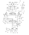
図1に、本発明の第1実施形態に係る建設機械の油圧駆動システム1Aを示し、図2に、その油圧駆動システム1Aが搭載された建設機械10を示す。図2に示す建設機械10は油圧ショベルであるが、本発明は、油圧クレーンなどの他の建設機械にも適用可能である。
(First embodiment)
FIG. 1 shows a hydraulic drive system 1A for a construction machine according to a first embodiment of the present invention, and FIG. 2 shows a
油圧駆動システム1Aは、油圧アクチュエータとして、図2に示すブームシリンダ11、アームシリンダ12およびバケットシリンダ13を含むとともに、図1に示す旋回油圧モータ14および図示しない左右一対の走行油圧モータを含む。また、油圧駆動システム1Aは、それらのアクチュエータへ作動油を供給するポンプ16と、ポンプ16を駆動するエンジン15を含む。なお、図1では、図面の簡略化のために、旋回油圧モータ14およびブームシリンダ11以外のアクチュエータを省略している。
The hydraulic drive system 1A includes a
本実施形態では、建設機械10が自走式の油圧ショベルであるが、建設機械10が船舶に搭載される油圧ショベルである場合には、運転室を含む旋回体が船体に旋回可能に支持される。
In this embodiment, the
ポンプ16は、傾転角が変更可能な可変容量型のポンプ(斜板ポンプまたは斜軸ポンプ)である。ポンプ16の傾転角は、ポンプレギュレータ17により調整される。ポンプ16の吐出流量は、ネガティブコントロール方式で制御されてもよいし、ポジティブコントロール方式で制御されてもよい。すなわち、ポンプレギュレータ17は、油圧により作動してもよいし、電気信号により作動してもよい。
The
ポンプ16は、供給ライン31により、ブーム制御弁41、旋回制御弁51およびその他の制御弁と接続されている。ブーム制御弁41は、ブームシリンダ11に対する作動油の供給および排出を制御し、旋回制御弁51は、旋回油圧モータ14に対する作動油の供給および排出を制御する。
The
より詳しくは、ブーム制御弁41は、ブーム上げ供給ライン45およびブーム下げ供給ライン46によりブームシリンダ11と接続されている。また、ブーム制御弁41は、ブーム排出ライン32により回生切換弁71と接続されている。回生切換弁71については後述にて詳細に説明する。
More specifically, the
ブーム制御弁41は一対のパイロットポートを有し、これらのパイロットポートは、ブーム上げパイロットライン43およびブーム下げパイロットライン44によりブーム操作弁42と接続されている。ブーム操作弁42は、操作レバーを含み、操作レバーの操作量(角度)に応じた大きさのパイロット圧をブーム制御弁41へ出力する。
The
一方、旋回制御弁51は、左旋回供給ライン61および右旋回供給ライン62により旋回油圧モータ14と接続されている。また、旋回制御弁51は、旋回排出ライン33により回生切換弁71と接続されている。
On the other hand, the turning
左旋回供給ライン61および右旋回供給ライン62同士は、橋架路63によって接続されている。橋架路63には、互いに逆向きに一対のリリーフ弁64が設けられている。左旋回供給ライン61と右旋回供給ライン62の間には、各リリーフ弁64をパイパスするようにバイパス路65が設けられており、各バイパス路65には逆止弁66が設けられている。橋架路63におけるリリーフ弁64の間の部分には、タンクライン67が接続されている。
The left
旋回制御弁51は、一対のパイロットポートを有している。一方のパイロットポートは、左旋回パイロットライン53により第1旋回操作比例弁55と接続されており、他方のパイロットポートは、右旋回パイロットライン54により第2旋回操作比例弁56と接続されている。第1および第2旋回操作比例弁55,56は、制御装置8から送給される電流に応じた大きさの二次圧を旋回制御弁51へ出力する。
The turning
本実施形態では、旋回操作用の操作レバーを含む旋回操作弁52として、操作レバーの操作量(角度)に応じた大きさのパイロット圧を出力するパイロット式操作弁が採用されている。制御装置8は、旋回操作弁52から出力される左旋回パイロット圧PLを計測する第1圧力計81と、旋回操作弁52から出力される右旋回パイロット圧PRを計測する第2圧力計82と接続されている。制御装置8は、通常(旋回減速時のエネルギを回生しないとき)は、旋回操作弁52から出力されるパイロット圧(PLまたはPR)と比例する電流を旋回操作比例弁(55または56)へ送給する。これにより、旋回操作比例弁(55または56)からは、旋回操作弁52から出力されるパイロット圧(PLまたはPR)に準じた二次圧が出力される。ただし、旋回操作弁52は、操作レバーの操作量(角度)に応じた大きさの電気信号を旋回信号として制御装置8に直接的に出力する電気式操作弁であってもよい。
In the present embodiment, a pilot type operation valve that outputs a pilot pressure having a magnitude corresponding to the operation amount (angle) of the operation lever is employed as the turning
さらに、本実施形態では、油圧駆動システム1Aが、ブーム下げ時のエネルギと旋回減速時のエネルギの双方を回生することができるように構成されている。そのための構成として、油圧駆動システム1Aは、回生油圧モータ18と上述した回生切換弁71を含む。
Furthermore, in the present embodiment, the hydraulic drive system 1A is configured so as to be able to regenerate both energy during boom lowering and energy during turning deceleration. As a configuration for that purpose, the hydraulic drive system 1A includes the regenerative
回生油圧モータ18は、ポンプ16と連結されている。回生油圧モータ18は、本実施形態では、固定容量型のモータである。
The regenerative
回生切換弁71は、回生ライン34により回生油圧モータ18と接続されている。また、回生切換弁71には、タンクライン35が接続されている。回生切換弁71は、中立位置と、ブーム回生位置(図1の右側位置)と、旋回回生位置(図1の左側位置)との間で切り換えられる。
The
回生切換弁71が中立位置に位置するとき、ブーム排出ライン32および旋回排出ライン33がタンクライン35と連通する。これにより、ブームシリンダ11から排出される作動油および旋回油圧モータ14から排出される作動油がタンクに導かれる。回生切換弁71がブーム回生位置に位置するとき、旋回排出ライン33がタンクライン35と連通する一方、ブーム排出ライン32が回生ライン34と連通する。これにより、ブームシリンダ11から排出された作動油が回生油圧モータ18に導かれる。回生切換弁71が旋回回生位置に位置するとき、ブーム排出ライン32がタンクライン35と連通する一方、旋回排出ライン33が回生ライン34と連通する。これにより、旋回油圧モータ14から排出された作動油が回生油圧モータ18に導かれる。
When the
本実施形態では、回生切換弁71が、ブーム回生位置でブーム排出ライン32と回生ライン34およびタンクライン35との連通度合を変更可能で、かつ、旋回回生位置で旋回排出ライン33と回生ライン34およびタンクライン35との連通度合を変更可能なパイロット式の可変絞りである。ただし、回生切換弁71は、電磁式の可変絞りであってもよい。
In the present embodiment, the
具体的に、回生切換弁71は、当該回生切換弁71をブーム回生位置に切り換えるためのブーム回生パイロットポート72と、当該回生切換弁71を旋回回生位置に切り換えるための旋回回生パイロットポート73を有している。ただし、回生切換弁71は、ブーム回生位置および旋回回生位置では排出ライン(32または33)を回生ライン34と100%連通させる、パイロット式または電磁式の単なる開閉弁であってもよい。
Specifically, the
ブーム回生パイロットポート72は、ブーム回生パイロットライン74によりブーム回生操作比例弁75と接続されている。旋回回生パイロットポート73は、旋回回生パイロットライン76により旋回回生操作比例弁77と接続されている。ブーム回生操作比例弁75および旋回回生操作比例弁77は、制御装置8から送給される電流に応じた大きさの二次圧を回生切換弁71へ出力する。
The boom
上述したエンジン15には、オルタネータ21が取り付けられている。オルタネータ21には、図3に示すように、第1蓄電器23が接続されており、第1蓄電器23には、第2蓄電器25が接続されている。第1蓄電器23は、通常の電装品の電圧よりも少し高めの電圧(例えば、48V)の蓄電器(例えば、キャパシタ)であり、第2蓄電器25は、通常の電装品の電圧(例えば、24V)と等しい電圧の蓄電器(例えば、バッテリ)である。第1蓄電器23には、中電圧の電気負荷26が接続されており、第2蓄電器25には、低電圧の電気負荷27が接続されている。
An
オルタネータ21と第1蓄電器23の間には、電力制御用の第1電力変換器22(例えば、インバータ)が介在しており、第1蓄電器23と第2蓄電器25の間には、電圧変換用の第2電力変換器24が介在している。
A first power converter 22 (for example, an inverter) for power control is interposed between the
オルタネータ21は、ベルトなどの動力伝達手段によりエンジン15の出力軸とつながれた回転軸(図示せず)を有する。オルタネータ21は、電力が供給されたときにエンジン15の出力軸を回転させ得るように構成されている。例えば、オルタネータ21は、公称電圧が30V以上(例えば、48V)の発電機である。これにより、一度の発電で多くの電力を第1蓄電器23に蓄積することができる。ただし、オルタネータ21の公称電圧は30V未満であってもよい。本実施形態では、オルタネータ21が交流発電機である。このため、第1電力変換器22は、AC−DCコンバータとしても機能する。
The
第1電力変換器22は、オルタネータ21と第1蓄電器23との間での電力伝達を可能とするサーボオン状態と、オルタネータ21と第1蓄電器23との間での電力伝達を不能とするサーボオフ状態との間で切り換えられる。第1電力変換器22は、制御装置8により、サーボオン状態とサーボオフ状態のどちらかに切り換えられる。制御装置8は、第1電力変換器22をサーボオン状態に切り換えたときには、第1電力変換器22を、オルタネータ21から第1蓄電器23へ伝達される電力を調整する充電モードと、第1蓄電器23からオルタネータ21へ伝達される電力を調整する放電モードのどちらかで制御する。
The
上述したように、制御装置8は、第1および第2旋回操作比例弁55,56、ブーム回生操作比例弁75および旋回回生操作比例弁77ならびに第1電力変換器22を制御する。具体的に、制御装置8は、上述した第1および第2圧力計81,82ならびに第3および第4圧力計83,84と接続されている。第3圧力計83は、ブーム下げ時にブーム操作弁42から出力されるパイロット圧を計測し、第4圧力計84は、ブーム上げ供給ライン45の圧力を計測する。
As described above, the control device 8 controls the first and second turning operation
次に、図4および図5を参照して、制御装置8が行う制御を説明する。本実施形態では、制御装置8が、旋回減速時のエネルギよりもブーム下げ時のエネルギを優先的に回生するようにブーム回生操作比例弁75および旋回回生操作比例弁77を介して回生切換弁71を制御する。また、本実施形態では、制御装置8が、ブーム充電条件と旋回充電条件のどちらかが満たされるときは、第1電力変換器22をサーボオン状態に切り換えるとともに充電モードで制御し、ブーム充電条件と旋回充電条件のどちらも満たされないときは、第1電力変換器22をサーボオフ状態に切り換えるか、第1電力変換器22をサーボオン状態に切り換えるとともに放電モードで制御する。
Next, control performed by the control device 8 will be described with reference to FIGS. In this embodiment, the control device 8 regenerates the
まず、制御装置8は、ブーム下げ時か否か(すなわち、第3圧力計83で計測されるパイロット圧がゼロより大きいか否か)を判定する(ステップS11)。ステップS11でYESの場合はステップS12へ進み、ステップS11でNOの場合はステップS15へ進む。
First, the control device 8 determines whether or not the boom is being lowered (that is, whether or not the pilot pressure measured by the
ステップS12では、制御装置8は、第1蓄電器23の蓄電量などにより第1蓄電器23への充電が可能か否かを判定する。制御装置8は、ステップS12でYESの場合は第1充電制御オンの処理を実行し(ステップS13)、ステップS12でNOの場合は充電制御オフの処理を実行する(ステップS14)。ステップS12でYESであること、すなわち、ブーム下げ時であるとともに第1蓄電器23が充電可能な状態であることが、ブーム充電条件である。 In step S <b> 12, the control device 8 determines whether or not the first battery 23 can be charged based on the amount of power stored in the first battery 23. If YES in step S12, control device 8 executes a first charge control on process (step S13), and if NO in step S12, executes a charge control off process (step S14). The boom charging condition is YES in step S12, that is, when the boom is lowered and the first battery 23 is in a chargeable state.
一方、ステップS15では、制御装置8は、旋回減速時か否か(すなわち、第1圧力計81で計測される左旋回パイロット圧PLまたは第2圧力計82で計測される右旋回パイロット圧PRが減少するか否か)を判定する。ステップS15でYESの場合はステップS16へ進み、ステップS15でNOの場合はステップS18へ進む。
On the other hand, in step S15, the control device 8 determines whether or not the vehicle is in deceleration deceleration (that is, the left-turn pilot pressure PL measured by the
ステップS16では、制御装置8は、第1蓄電器23の蓄電量などにより第1蓄電器23への充電が可能か否かを判定する。制御装置8は、ステップS16でYESの場合は第2充電制御オンの処理を実行し(ステップS17)、ステップS16でNOの場合は充電制御オフの処理を実行する(ステップS14)。ステップS16でYESであること、すなわち、旋回減速時であるとともに第1蓄電器23が充電可能な状態であることが、旋回充電条件である。 In step S <b> 16, the control device 8 determines whether or not the first battery 23 can be charged based on the amount of power stored in the first battery 23. If YES at step S16, control device 8 executes a process for turning on the second charge control (step S17), and if NO at step S16, it executes a process for turning off charge control (step S14). It is YES in step S16, that is, the turning charging condition is that the first battery 23 is in a chargeable state while turning and decelerating.
ブーム充電条件が満たされた場合の第1充電制御オンでは、図5(a)に示すように、制御装置8は、まず第1電力変換器22をサーボオン状態に切り換える(ステップS31)。ついで、制御装置8は、ブーム回生操作比例弁75へ所定の大きさの電流を送給して、回生切換弁71をブーム回生位置へ切り換える(ステップS32)。このときに制御装置8からブーム回生操作比例弁75へ送給される電流の大きさは、例えば、第3圧力計83で計測されるブーム下げパイロットライン44の圧力に基づいて決定される。その後、制御装置8は、第1電力変換器22を充電モードで制御する(ステップS34)。
When the first charging control is on when the boom charging condition is satisfied, as shown in FIG. 5A, the control device 8 first switches the
ステップS31、S32、S34の結果、ブーム下げ時に回生油圧モータ18で回収したエネルギを電気エネルギとして第1蓄電器23に蓄積することができる。なお、制御装置8は、第1充電制御オンの処理を実行中は、旋回操作弁52から出力されるパイロット圧(PLまたはPR)と比例する電流を旋回操作比例弁(55または56)へ送給し、第1および第2旋回操作比例弁55,56の出力を、旋回操作弁52から出力されるパイロット圧PL,PRに準じた圧力とする(ステップS35)。
As a result of steps S31, S32, and S34, the energy collected by the regenerative
一方、ブーム下げ時でも第1蓄電器23への充電が不可の場合の充電制御オフでは、図5(c)に示すように、制御装置8は、まず第1電力変換器22をサーボオフ状態に切り換える(ステップS51)。ついで、制御装置8は、ブーム回生操作比例弁75および旋回回生操作比例弁77のどちらにも電流を送給せずに、回生切換弁71を中立位置へ切り換える(ステップS52)。充電制御オフの処理を実行中も、第1充電制御オンの処理を実行中と同様に、第1および第2旋回操作比例弁55,56の出力を、旋回操作弁52から出力されるパイロット圧に準じた圧力とする(ステップS54)。
On the other hand, when the charging control is turned off when the first battery 23 cannot be charged even when the boom is lowered, the control device 8 first switches the
旋回充電条件が満たされた場合の第2充電制御オンでは、図5(b)に示すように、制御装置8は、まず第1電力変換器22をサーボオン状態に切り換える(ステップS41)。ついで、制御装置8は、旋回回生操作比例弁77へ所定の大きさの電流を送給して、回生切換弁71を旋回回生位置へ切り換える(ステップS42)。このときに制御装置8から旋回回生操作比例弁77へ送給される電流の大きさは、例えば、エンジン15の回転数に基づいて決定される。その後、制御装置8は、第1電力変換器22を充電モードで制御する(ステップS44)。
When the second charging control is on when the turning charging condition is satisfied, as shown in FIG. 5B, the control device 8 first switches the
ステップS41、S42、S44の結果、旋回減速時に回生油圧モータ18で回収したエネルギを電気エネルギとして第1蓄電器23に蓄積することができる。なお、制御装置8は、第2充電制御オンの処理を実行中は、第1および第2旋回操作比例弁55,56の出力を、旋回制御弁51で作動油が絞られない圧力とする(ステップS45)。例えば、制御装置8は、旋回制御弁51の開口面積が最大となるように、第1旋回操作比例弁55または第2旋回操作比例弁56へ電流を送給する。あるいは、制御装置8は、第2充電制御オンの処理を実行中は、旋回制御弁51の位置が変わらないように、旋回減速前の電流を維持してもよい。
As a result of steps S41, S42, and S44, the energy recovered by the regenerative
一方、旋回減速時でも第1蓄電器23への充電が不可の場合の充電制御オフでは、上述した図5(c)に示すフローに従った制御が行われる。 On the other hand, when charging control is off when charging to the first battery 23 is impossible even during turning deceleration, control according to the flow shown in FIG. 5C is performed.
ブーム下げ時でも旋回減速時でもない場合には、制御装置8は充電制御オフの処理を実行する(ステップS18)。この場合のフローも、図5(c)に示すとおりである。ただし、ブーム下げ時でも旋回減速時でもない場合には、充電制御オフの処理の実行後に、さらなる処理が行われる。 If neither the boom lowering nor the turning deceleration is performed, the control device 8 executes a charging control off process (step S18). The flow in this case is also as shown in FIG. However, if the boom is not lowered or the vehicle is decelerating, further processing is performed after execution of the charging control off processing.
まず、制御装置8は、第1蓄電器23の蓄電量などにより第1蓄電器23からの放電が可能か否かを判定する(ステップS19)。ステップS19でNOの場合は、制御装置8は放電制御オフの処理を実行する(ステップS22)。具体的には、制御装置8は、第1電力変換器22をサーボオフ状態に維持する。
First, the control device 8 determines whether or not the discharge from the first battery 23 is possible based on the amount of power stored in the first battery 23 (step S19). In the case of NO in step S19, the control device 8 executes a discharge control off process (step S22). Specifically, the control device 8 maintains the
ステップS19でYESの場合は、制御装置8は、さらに現在の状態が負荷状態か否かを判定する(ステップS20)。負荷状態か否かは、例えば、ポンプ16の吐出圧、ポンプレギュレータ17への指令などにより判定することができる。ステップS20でNOの場合も、ステップS22に進む。一方、ステップS20でYESの場合は、制御装置8は、放電制御オンの処理を実行する(ステップS21)。具体的には、制御装置8は、第1電力変換器22をサーボオン状態に切り換えるとともに放電モードで制御する。これにより、第1蓄電器23に蓄積された電力でポンプ16の駆動をアシストすることができる。
If YES in step S19, control device 8 further determines whether or not the current state is a load state (step S20). Whether or not it is in a load state can be determined by, for example, the discharge pressure of the
以上説明したように、本実施形態の油圧駆動システム1Aでは、エンジン15により駆動されるポンプ16に回生油圧モータ18が連結されているので、エンジン15に取り付けられたオルタネータ21を利用して、換言すればエンジン15から見てポンプ16側(負荷側)に電動発電機を別途設置することなく、回生油圧モータ18で回収したエネルギを電気エネルギとして第1蓄電器23に蓄積することができる。しかも、オルタネータ21と第1蓄電器23の間に第1電力変換器22が介在しているので、オルタネータ21から第1蓄電器23への電力伝達を制御することができる。
As described above, in the hydraulic drive system 1A of the present embodiment, since the regenerative
<変形例>
前記実施形態では、ブーム下げ時および旋回減速時の充電制御オフの処理(ステップS14)では、回生切換弁71を中立位置に切り換えたが、回生切換弁71は、ブーム下げ時は常にブーム回生位置に維持され、旋回減速時は常に旋回回生位置に維持されてもよい。このようにすれば、電力を第1蓄電器23に蓄積する代わりに、回生油圧モータ18で回収したエネルギでポンプ16の駆動をアシストすることができる。
<Modification>
In the above-described embodiment, the
また、回生切換弁71は、必ずしも単一の3位置弁である必要はなく、ブーム排出ライン32が接続されたブーム側2位置弁と旋回排出ライン33が接続された旋回側2位置弁の一対の2位置弁で構成されてもよい。
The
また、前記実施形態では、油圧駆動システム1Aがブーム下げ時のエネルギと旋回減速時のエネルギの双方を回生することができるように構成されていたが、油圧駆動システム1Aは、ブーム下げ時のエネルギと旋回減速時のエネルギのどちらか一方のみを回生することができるように構成されていてもよい。すなわち、ブーム制御弁41と旋回制御弁51のどちらかには、排出ライン(32または33)の代わりにタンクラインが接続されていてもよい。この場合、回生切換弁71が2位置弁となることは言うまでもない。
In the embodiment, the hydraulic drive system 1A is configured to regenerate both the energy at the time of lowering the boom and the energy at the time of turning deceleration. However, the hydraulic drive system 1A has the energy at the time of lowering the boom. It is also possible to regenerate only one of the energy at the time of turning and deceleration. That is, a tank line may be connected to either the
例えば、回生油圧モータ18に、ブーム下げ時にブームシリンダ11から排出される作動油のみが導かれる場合は、制御装置8は、ブーム充電条件が満たされるときは、第1電力変換器22をサーボオン状態に切り換えるとともに充電モードで制御し、ブーム充電条件が満たされないときは、第1電力変換器22をサーボオフ状態に切り換えるか、第1電力変換器22をサーボオン状態に切り換えるとともに放電モードで制御してもよい。
For example, when only the hydraulic oil discharged from the
(第2実施形態)
次に、図6および図7(a)〜(c)を参照して、本発明の第2実施形態に係る建設機械の油圧駆動システム1Bを説明する。なお、本実施形態において、第1実施形態と同一構成要素には同一符号を付し、重複した説明は省略する。
(Second Embodiment)
Next, a
本実施形態では、回生油圧モータ18が、傾転角が変更可能な可変容量型のモータ(斜板モータまたは斜軸モータ)である。回生油圧モータ18の傾転角は、回生油圧モータレギュレータ19により調整される。本実施形態では、回生油圧モータレギュレータ19は、電気信号により作動する。すなわち、回生油圧モータレギュレータ19は、制御装置8により制御される。例えば、回生油圧モータ18が斜板モータである場合、回生油圧モータレギュレータ19は、モータの斜板と連結されたスプールに作用する油圧を電気的に変更するものであってもよいし、モータの斜板と連結された電動アクチュエータであってもよい。
In the present embodiment, the regenerative
本実施形態では、制御装置8が、旋回油圧モータ14の回転数を計測する回転数計85と接続されている。制御装置8は、第1実施形態と同様に、図4に示すフローチャートに従った制御を行うが、図7(a)〜(c)に示すように、第1充電制御オン(図4のステップS13)、第2充電制御オン(図4のステップS17)および充電制御オフ(図4のステップS14,S18)の処理において、回生油圧モータレギュレータ19も制御する。
In the present embodiment, the control device 8 is connected to a
第1充電制御オンでは、ステップS32の後であってステップS34の前に、制御装置8は、回生油圧モータレギュレータ19を介して、ブーム下げ時の因子に基づいて回生油圧モータ18の傾転角を調整する(ステップS33)。例えば、制御装置8は、ブーム操作弁42の操作量が大きくなるほど回生油圧モータ18の傾転角が大きくなるように、回生油圧モータレギュレータ19を制御する。これにより、ブーム下げの速度に応じた適切なエネルギ回収を行うことができる。ブーム操作弁42の操作量としては、第3圧力計83で計測されるブーム下げパイロットライン44の圧力を用いてもよいし、第4圧力計84で計測されるブーム上げ供給ライン45の圧力を用いてもよい。
When the first charging control is ON, after step S32 and before step S34, the control device 8 causes the tilt angle of the regenerative
第2充電制御オンでは、ステップS42の後であってステップS44の前に、制御装置8は、回生油圧モータレギュレータ19を介して、旋回減速時の因子に基づいて回生油圧モータ18の傾転角を調整する(ステップS43)。例えば、制御装置8は、回転数計85で計測される旋回油圧モータ14の回転数が高くなるほど回生油圧モータ18の傾転角が大きくなるように、回生油圧モータレギュレータ19を制御する。これにより、旋回速度に応じた適切なエネルギ回収を行うことができる。なお、本実施形態のように回転数計85が設けられる場合は、ステップS42において制御装置8から旋回回生操作比例弁77へ送給される電流の大きさは、回転数計85で計測される旋回油圧モータ14の回転数に基づいて決定されてもよい。
When the second charge control is on, after step S42 and before step S44, the control device 8 causes the tilt angle of the regenerative
充電制御オフでは、ステップS52の後であってステップS54の前に、制御装置8は、回生油圧モータ18の傾転角が最小となるように回生油圧モータレギュレータ19を制御する(ステップS53)。
When the charging control is off, after step S52 and before step S54, the control device 8 controls the regenerative
本実施形態でも、第1実施形態と同様の効果を得ることができる。 Also in this embodiment, the same effect as the first embodiment can be obtained.
(第3実施形態)
次に、図8を参照して、本発明の第3実施形態に係る建設機械の油圧駆動システム1Cを説明する。なお、本実施形態において、第1および第2実施形態と同一構成要素には同一符号を付し、重複した説明は省略する。
(Third embodiment)
Next, with reference to FIG. 8, a
本実施形態では、ブーム制御弁41がブーム排出ライン37により回生油圧モータ18と接続されており、ブーム制御弁41にはタンクライン36が接続されている。そして、ブーム制御弁41は、ブーム上げ時にはブームシリンダ11から排出される作動油が当該ブーム制御弁41からタンクライン36へ流入し、ブーム下げ時にはブームシリンダ11から排出される作動油が当該ブーム制御弁41から排出ライン37へ流入するように構成されている。この構成により、ブームシリンダ11から排出される作動油をブーム下げ時に自動的に回生油圧モータ18へ導くことができる。
In the present embodiment, the
より詳しくは、ブーム制御弁41がブーム上げ方向に移動すると、供給ライン31がブーム上げ供給ライン45と連通するとともに、ブーム下げ供給ライン46がタンクライン36と連通する。逆に、ブーム制御弁41がブーム下げ方向に移動すると、供給ライン31がブーム下げ供給ライン46と連通するとともに、ブーム上げ供給ライン45がブーム排出ライン37と連通する。
More specifically, when the
また、本実施形態では、旋回制御弁51が、旋回排出ライン33により回生切換弁78と接続されている。回生切換弁78は、回生ライン38によりブーム排出ライン37と接続されており、回生切換弁78には、タンクライン35が接続されている。
In this embodiment, the turning
回生切換弁78は、旋回排出ライン33がタンクライン35と連通する非回生位置と、旋回排出ライン33が回生ライン38と連通する回生位置との間で切り換えられる。本実施形態では、回生切換弁78が、制御装置8により駆動される電磁式の開閉弁である。本実施形態でも、旋回減速時のエネルギよりもブーム下げ時のエネルギが優先的に回生される。すなわち、制御装置8は、旋回減速時であってもブーム下げ時でもあるときは回生切換弁78を非回生位置に維持し、旋回減速時であってブーム下げ時でないときに回生切換弁78を回生位置に切り換える。なお、回生切換弁78の制御以外は、制御装置8は、第1実施形態と同様に、図4および図5(a)〜(c)に示すフローチャートに従った制御を行う。
The
本実施形態でも、第1実施形態と同様の効果を得ることができる。 Also in this embodiment, the same effect as the first embodiment can be obtained.
なお、図9に示す変形例の油圧駆動システム1Dのように、回生油圧モータ18が第2実施形態と同様に可変容量型のモータであってもよいこと、および旋回油圧モータ14の回転数を計測する回転数計85が設けられてもよいことは言うまでもない。
As in the modified example of the
(第4実施形態)
次に、図10を参照して、本発明の第4実施形態に係る建設機械の油圧駆動システム1Eを説明する。なお、本実施形態において、第1〜第3実施形態と同一構成要素には同一符号を付し、重複した説明は省略する。
(Fourth embodiment)
Next, with reference to FIG. 10, the
本実施形態では、旋回制御弁51のパイロットポートが、左旋回パイロットライン53および右旋回パイロットライン54により旋回操作弁52と接続されている。すなわち、旋回制御弁51は、常に、旋回操作弁52の操作レバーの操作量(角度)に応じて移動する。
In the present embodiment, the pilot port of the turning
また、本実施形態では、左旋回供給ライン61と右旋回供給ライン62の間に、旋回供給ライン61,62のどちらかを選択するための切換弁91が設けられている。切換弁91は、旋回排出ライン92により回生切換弁78と接続されている。
In the present embodiment, a switching
本実施形態では、切換弁91が、制御装置8により駆動される電磁式の開閉弁であるが、単なる高圧選択弁であってもよい。制御装置8は、切換弁91を、左旋回減速時に排出側の右旋回供給ライン62が排出ライン92と連通する第1位置に切り換え、右旋回減速時に排出側の左旋回供給ライン61が排出ライン92と連通する第2位置に切り換える。旋回減速時以外は、切換弁91は第1位置と第2位置のどちらに位置していてもよい。
In the present embodiment, the switching
回生切換弁78は、第3実施形態では3ポートであったが、本実施形態では2ポートである。すなわち、回生切換弁78にはタンクライン35(図8参照)が接続されていない。そして、回生切換弁78は、非回生位置では旋回排出ライン92と回生ライン38とを遮断し、回生位置では旋回排出ライン92を回生ライン38と連通させる。
The
第3実施形態と同様に、制御装置8は、旋回減速時であってもブーム下げ時でもあるときは回生切換弁78を非回生位置に維持し、旋回減速時であってブーム下げ時でないときに回生切換弁78を回生位置に切り換える。なお、切換弁91および回生切換弁78の制御ならびに旋回操作比例弁の制御がないこと以外は、制御装置8は、第1実施形態と同様に、図4および図5(a)〜(c)に示すフローチャートに従った制御を行う。
As in the third embodiment, the control device 8 maintains the
本実施形態でも、第1実施形態と同様の効果を得ることができる。また、本実施形態では、旋回操作弁52と旋回制御弁51の間のパイロット回路を通常のシンプルな構成とすることができる。
Also in this embodiment, the same effect as the first embodiment can be obtained. In the present embodiment, the pilot circuit between the
なお、図11に示す変形例の油圧駆動システム1Fのように、回生油圧モータ18が第2実施形態と同様に可変容量型のモータであってもよいこと、および旋回油圧モータ14の回転数を計測する回転数計85が設けられてもよいことは言うまでもない。
In addition, like the
(その他の実施形態)
本発明は上述した第1〜第4実施形態に限定されるものではなく、本発明の要旨を逸脱しない範囲で種々の変形が可能である。
(Other embodiments)
The present invention is not limited to the first to fourth embodiments described above, and various modifications can be made without departing from the gist of the present invention.
例えば、第1〜第4実施形態において、回生油圧モータ18とポンプ16の間にワンウェイクラッチが設けられていてもよい。
For example, in the first to fourth embodiments, a one-way clutch may be provided between the regenerative
また、第2蓄電器25および第2電力変換器24は、設けられていなくてもよい。 Moreover, the 2nd electrical storage device 25 and the 2nd power converter 24 do not need to be provided.
1A〜1C 油圧駆動システム
8 制御装置
10 建設機械
11 ブームシリンダ
14 旋回油圧モータ
15 エンジン
16 ポンプ
18 回生油圧モータ
19 回生油圧モータレギュレータ
21 オルタネータ
22 第1電力変換器
23 第1蓄電器
32,37 ブーム排出ライン
35,36 タンクライン
41 ブーム制御弁
51 旋回制御弁
55,56 旋回操作比例弁
71 回生切換弁
75 ブーム回生操作比例弁
77 旋回回生操作比例弁
DESCRIPTION OF SYMBOLS 1A-1C Hydraulic drive system 8
Claims (7)
前記ポンプと連結された回生油圧モータであって、ブーム下げ時に前記ブームシリンダから排出される作動油および/または旋回減速時に前記旋回油圧モータから排出される作動油が導かれる回生油圧モータと、
前記ポンプを駆動するエンジンと、
前記エンジンに取り付けられたオルタネータであって、電力が供給されたときに前記エンジンの出力軸を回転させ得るオルタネータと、
前記オルタネータと接続された蓄電器と、
前記オルタネータと前記蓄電器との間に介在する電力変換器であって、前記オルタネータと前記蓄電器との間での電力伝達を可能とするサーボオン状態と、前記オルタネータと前記蓄電器との間での電力伝達を不能とするサーボオフ状態との間で切り換えられる電力変換器と、
前記電力変換器を前記サーボオン状態と前記サーボオフ状態のどちらかに切り換えるとともに、前記電力変換器を前記サーボオン状態に切り換えたときには、前記電力変換器を、前記オルタネータから前記蓄電器へ伝達される電力を調整する充電モードと前記蓄電器から前記オルタネータへ伝達される電力を調整する放電モードのどちらかで制御する制御装置と、
を備える、建設機械の油圧駆動システム。 A pump for supplying hydraulic oil to the boom cylinder and the swing hydraulic motor;
A regenerative hydraulic motor connected to the pump, wherein the hydraulic oil discharged from the boom cylinder when the boom is lowered and / or the hydraulic oil discharged from the swivel hydraulic motor during turning deceleration is guided;
An engine for driving the pump;
An alternator attached to the engine, the alternator capable of rotating the output shaft of the engine when electric power is supplied;
A capacitor connected to the alternator;
A power converter interposed between the alternator and the battery, wherein the servo-on state enables power transfer between the alternator and the battery, and power transfer between the alternator and the battery. A power converter that is switched between a servo-off state that disables
The power converter is switched to either the servo-on state or the servo-off state, and when the power converter is switched to the servo-on state, the power converter adjusts the power transmitted from the alternator to the capacitor. A control device that controls in either a charge mode to perform and a discharge mode that adjusts power transmitted from the capacitor to the alternator;
A hydraulic drive system for construction machinery.
前記制御装置は、ブーム下げ時であるとともに前記蓄電器が充電可能な状態であるブーム充電条件が満たされるときは、前記電力変換器を前記サーボオン状態に切り換えるとともに前記充電モードで制御し、前記ブーム充電条件が満たされないときは、前記電力変換器を前記サーボオフ状態に切り換えるか、前記電力変換器を前記サーボオン状態に切り換えるとともに前記放電モードで制御する、請求項1に記載の建設機械の油圧駆動システム。 The regenerative hydraulic motor is guided with hydraulic oil discharged from the boom cylinder when the boom is lowered,
The control device switches the power converter to the servo-on state and controls in the charging mode when the boom charging condition is satisfied when the boom is lowered and the battery can be charged, and the boom charging is performed. 2. The hydraulic drive system for a construction machine according to claim 1, wherein when the condition is not satisfied, the power converter is switched to the servo-off state, or the power converter is switched to the servo-on state and controlled in the discharge mode.
前記制御装置は、ブーム下げ時であるとともに前記蓄電器が充電可能な状態であるブーム充電条件と、旋回減速時であるとともに前記蓄電器が充電可能な状態である旋回充電条件のどちらかが満たされるときは、前記電力変換器を前記サーボオン状態に切り換えるとともに前記充電モードで制御し、前記ブーム充電条件と前記旋回充電条件のどちらも満たされないときは、前記電力変換器を前記サーボオフ状態に切り換えるか、前記電力変換器を前記サーボオン状態に切り換えるとともに前記放電モードで制御する、請求項1に記載の建設機械の油圧駆動システム。 The regenerative hydraulic motor is guided with hydraulic oil discharged from the boom cylinder when the boom is lowered, and is also guided with hydraulic oil discharged from the swing hydraulic motor at the time of turning deceleration,
The control device satisfies a boom charging condition in which the battery is in a chargeable state while the boom is lowered and a turning charging condition in which the battery is in a chargeable state while turning and deceleration is satisfied. Switching the power converter to the servo-on state and controlling in the charging mode, and when neither the boom charging condition nor the turning charging condition is satisfied, the power converter is switched to the servo-off state, The hydraulic drive system for a construction machine according to claim 1, wherein the power converter is switched to the servo-on state and controlled in the discharge mode.
前記ブーム制御弁は、ブーム上げ時には前記ブームシリンダから排出される作動油が当該ブーム制御弁から前記タンクラインへ流入し、ブーム下げ時には前記ブームシリンダから排出される作動油が当該ブーム制御弁から前記ブーム排出ラインへ流入するように構成されている、請求項2または3に記載の建設機械の油圧駆動システム。 A boom control valve for controlling supply and discharge of hydraulic oil to and from the boom cylinder is provided, the boom control valve is connected to the regenerative hydraulic motor by a boom discharge line, and a tank line is connected to the boom control valve. And
In the boom control valve, when the boom is raised, the hydraulic oil discharged from the boom cylinder flows into the tank line from the boom control valve, and when the boom is lowered, the hydraulic oil is discharged from the boom cylinder from the boom control valve. The hydraulic drive system for a construction machine according to claim 2 or 3, wherein the hydraulic drive system is configured to flow into a boom discharge line.
前記回生油圧モータの傾転角を調整する回生油圧モータレギュレータを備え、
前記制御装置は、旋回減速時であるとともに前記蓄電器が充電可能な状態である旋回充電条件が満たされるときに、前記旋回油圧モータの回転数が高くなるほど前記回生油圧モータの傾転角が大きくなるように、前記回生油圧モータレギュレータを制御する、請求項1〜4のいずれか一項に記載の建設機械の油圧駆動システム。 The regenerative hydraulic motor is a variable capacity motor whose tilt angle can be changed,
A regenerative hydraulic motor regulator for adjusting a tilt angle of the regenerative hydraulic motor;
The control device increases the tilt angle of the regenerative hydraulic motor as the rotational speed of the swing hydraulic motor increases when a swing charging condition in which the storage battery can be charged is satisfied while the vehicle is decelerating while turning. As described above, the hydraulic drive system for a construction machine according to any one of claims 1 to 4, which controls the regenerative hydraulic motor regulator.
前記回生油圧モータの傾転角を調整する回生油圧モータレギュレータを備え、
前記制御装置は、ブーム下げ時であるとともに前記蓄電器が充電可能な状態であるブーム充電条件が満たされるときに、ブーム操作弁の操作量が大きくなるほど前記回生油圧モータの傾転角が大きくなるように、前記回生油圧モータレギュレータを制御する、請求項1〜5のいずれか一項に記載の建設機械の油圧駆動システム。 The regenerative hydraulic motor is a variable capacity motor whose tilt angle can be changed,
A regenerative hydraulic motor regulator for adjusting a tilt angle of the regenerative hydraulic motor;
The control device is configured to increase the tilt angle of the regenerative hydraulic motor as the operation amount of the boom operation valve increases when a boom charging condition in which the battery is chargeable is satisfied while the boom is lowered. The hydraulic drive system for a construction machine according to any one of claims 1 to 5, wherein the regenerative hydraulic motor regulator is controlled.
Priority Applications (5)
| Application Number | Priority Date | Filing Date | Title |
|---|---|---|---|
| JP2014249816A JP6270704B2 (en) | 2014-12-10 | 2014-12-10 | Hydraulic drive system for construction machinery |
| PCT/JP2015/006069 WO2016092808A1 (en) | 2014-12-10 | 2015-12-07 | Hydraulic drive system for construction machinery |
| CN201580062114.1A CN107002724B (en) | 2014-12-10 | 2015-12-07 | The oil pressure actuated systems of building machinery |
| US15/535,217 US10167613B2 (en) | 2014-12-10 | 2015-12-07 | Hydraulic drive system of construction machine |
| GB1709325.3A GB2547869B (en) | 2014-12-10 | 2015-12-07 | Hydraulic drive system for construction machine |
Applications Claiming Priority (1)
| Application Number | Priority Date | Filing Date | Title |
|---|---|---|---|
| JP2014249816A JP6270704B2 (en) | 2014-12-10 | 2014-12-10 | Hydraulic drive system for construction machinery |
Publications (3)
| Publication Number | Publication Date |
|---|---|
| JP2016109271A JP2016109271A (en) | 2016-06-20 |
| JP2016109271A5 JP2016109271A5 (en) | 2017-07-06 |
| JP6270704B2 true JP6270704B2 (en) | 2018-01-31 |
Family
ID=56107028
Family Applications (1)
| Application Number | Title | Priority Date | Filing Date |
|---|---|---|---|
| JP2014249816A Active JP6270704B2 (en) | 2014-12-10 | 2014-12-10 | Hydraulic drive system for construction machinery |
Country Status (5)
| Country | Link |
|---|---|
| US (1) | US10167613B2 (en) |
| JP (1) | JP6270704B2 (en) |
| CN (1) | CN107002724B (en) |
| GB (1) | GB2547869B (en) |
| WO (1) | WO2016092808A1 (en) |
Families Citing this family (4)
| Publication number | Priority date | Publication date | Assignee | Title |
|---|---|---|---|---|
| US10359063B2 (en) * | 2014-11-24 | 2019-07-23 | Xuzhou Heavy Machinery Co.., Ltd. | Method and system for recovering and utilizing operating energy of crane, and crane |
| CN106224329B (en) * | 2016-09-08 | 2018-02-13 | 北京精密机电控制设备研究所 | A kind of integrated electric Hydrauservo System |
| JP6726127B2 (en) * | 2017-03-30 | 2020-07-22 | 川崎重工業株式会社 | Hydraulic system |
| JP7357465B2 (en) | 2019-05-22 | 2023-10-06 | 川崎重工業株式会社 | hydraulic system |
Family Cites Families (12)
| Publication number | Priority date | Publication date | Assignee | Title |
|---|---|---|---|---|
| JPH0860705A (en) | 1994-08-19 | 1996-03-05 | Shin Caterpillar Mitsubishi Ltd | Output support device of construction equipment |
| JP2001197785A (en) * | 1999-11-04 | 2001-07-19 | Shin Caterpillar Mitsubishi Ltd | Circuit device |
| JP4179465B2 (en) * | 2002-07-31 | 2008-11-12 | 株式会社小松製作所 | Construction machinery |
| JP2006336549A (en) * | 2005-06-02 | 2006-12-14 | Shin Caterpillar Mitsubishi Ltd | Hybrid type drive device |
| US7827787B2 (en) * | 2007-12-27 | 2010-11-09 | Deere & Company | Hydraulic system |
| JP5350290B2 (en) * | 2010-02-18 | 2013-11-27 | カヤバ工業株式会社 | Control device for hybrid construction machine |
| JP5350292B2 (en) * | 2010-02-23 | 2013-11-27 | カヤバ工業株式会社 | Control device for hybrid construction machine |
| US8362629B2 (en) * | 2010-03-23 | 2013-01-29 | Bucyrus International Inc. | Energy management system for heavy equipment |
| JP5323753B2 (en) * | 2010-03-26 | 2013-10-23 | カヤバ工業株式会社 | Construction machine control equipment |
| JP5806825B2 (en) * | 2011-03-17 | 2015-11-10 | カヤバ工業株式会社 | Control controller for hybrid construction machinery |
| US8606448B2 (en) * | 2011-06-29 | 2013-12-10 | Caterpillar Inc. | System and method for managing power in machine having electric and/or hydraulic devices |
| US8839617B2 (en) * | 2011-09-30 | 2014-09-23 | Caterpillar Inc. | System and method for controlling charging of an accumulator in an electro-hydraulic system |
-
2014
- 2014-12-10 JP JP2014249816A patent/JP6270704B2/en active Active
-
2015
- 2015-12-07 GB GB1709325.3A patent/GB2547869B/en active Active
- 2015-12-07 CN CN201580062114.1A patent/CN107002724B/en active Active
- 2015-12-07 WO PCT/JP2015/006069 patent/WO2016092808A1/en active Application Filing
- 2015-12-07 US US15/535,217 patent/US10167613B2/en active Active
Also Published As
| Publication number | Publication date |
|---|---|
| JP2016109271A (en) | 2016-06-20 |
| US10167613B2 (en) | 2019-01-01 |
| GB2547869A (en) | 2017-08-30 |
| CN107002724A (en) | 2017-08-01 |
| US20170342685A1 (en) | 2017-11-30 |
| WO2016092808A1 (en) | 2016-06-16 |
| CN107002724B (en) | 2018-12-14 |
| GB201709325D0 (en) | 2017-07-26 |
| GB2547869B (en) | 2020-07-08 |
Similar Documents
| Publication | Publication Date | Title |
|---|---|---|
| US9290908B2 (en) | Hybrid construction machine | |
| US8991184B2 (en) | Hybrid construction machine | |
| JP4524679B2 (en) | Hybrid construction machinery | |
| JP5511425B2 (en) | Control device for hybrid construction machine | |
| KR101834589B1 (en) | Construction machine having rotary element | |
| WO2012105345A1 (en) | Power regeneration device for work machine | |
| WO2006022043A1 (en) | Hydraulic pressure drive circuit | |
| JP6197527B2 (en) | Hybrid construction machinery | |
| JP2009052339A (en) | Operation control method of hybrid type working machine and working machine using the same method | |
| US9777463B2 (en) | Construction machine | |
| JP6270704B2 (en) | Hydraulic drive system for construction machinery | |
| JP5873456B2 (en) | Work machine drive control system, work machine including the same, and drive control method thereof | |
| KR20160106679A (en) | Construction machine | |
| JP2009264024A (en) | Control device of hybrid construction machine | |
| EP3085969B1 (en) | Construction machine | |
| JP6383226B2 (en) | Work machine drive system | |
| JP6401668B2 (en) | Control system and control method for hybrid construction machine | |
| JP5731331B2 (en) | Power regeneration device for work machines | |
| JP2012210032A (en) | Power storage device and hybrid construction machine | |
| JP2013068291A (en) | Power regenerating device for working machine | |
| WO2018051644A1 (en) | Control system and control method for hybrid construction machine | |
| JP6514895B2 (en) | Drive control system for working machine, working machine including the same, and drive control method thereof | |
| JP5723947B2 (en) | Construction machine having a rotating body | |
| JP2014083908A (en) | Construction machine |
Legal Events
| Date | Code | Title | Description |
|---|---|---|---|
| A621 | Written request for application examination |
Free format text: JAPANESE INTERMEDIATE CODE: A621 Effective date: 20170227 |
|
| A521 | Request for written amendment filed |
Free format text: JAPANESE INTERMEDIATE CODE: A523 Effective date: 20170525 |
|
| TRDD | Decision of grant or rejection written | ||
| A01 | Written decision to grant a patent or to grant a registration (utility model) |
Free format text: JAPANESE INTERMEDIATE CODE: A01 Effective date: 20171205 |
|
| A61 | First payment of annual fees (during grant procedure) |
Free format text: JAPANESE INTERMEDIATE CODE: A61 Effective date: 20171226 |
|
| R150 | Certificate of patent or registration of utility model |
Ref document number: 6270704 Country of ref document: JP Free format text: JAPANESE INTERMEDIATE CODE: R150 |
|
| R250 | Receipt of annual fees |
Free format text: JAPANESE INTERMEDIATE CODE: R250 |