RU2688503C2 - Connecting device of bicycle wheel (versions) - Google Patents
Connecting device of bicycle wheel (versions) Download PDFInfo
- Publication number
- RU2688503C2 RU2688503C2 RU2015128313A RU2015128313A RU2688503C2 RU 2688503 C2 RU2688503 C2 RU 2688503C2 RU 2015128313 A RU2015128313 A RU 2015128313A RU 2015128313 A RU2015128313 A RU 2015128313A RU 2688503 C2 RU2688503 C2 RU 2688503C2
- Authority
- RU
- Russia
- Prior art keywords
- component
- axial
- frame
- bicycle
- hole
- Prior art date
Links
Images


Classifications
-
- B—PERFORMING OPERATIONS; TRANSPORTING
- B62—LAND VEHICLES FOR TRAVELLING OTHERWISE THAN ON RAILS
- B62K—CYCLES; CYCLE FRAMES; CYCLE STEERING DEVICES; RIDER-OPERATED TERMINAL CONTROLS SPECIALLY ADAPTED FOR CYCLES; CYCLE AXLE SUSPENSIONS; CYCLE SIDECARS, FORECARS, OR THE LIKE
- B62K25/00—Axle suspensions
- B62K25/02—Axle suspensions for mounting axles rigidly on cycle frame or fork, e.g. adjustably
-
- B—PERFORMING OPERATIONS; TRANSPORTING
- B62—LAND VEHICLES FOR TRAVELLING OTHERWISE THAN ON RAILS
- B62M—RIDER PROPULSION OF WHEELED VEHICLES OR SLEDGES; POWERED PROPULSION OF SLEDGES OR SINGLE-TRACK CYCLES; TRANSMISSIONS SPECIALLY ADAPTED FOR SUCH VEHICLES
- B62M1/00—Rider propulsion of wheeled vehicles
-
- B—PERFORMING OPERATIONS; TRANSPORTING
- B62—LAND VEHICLES FOR TRAVELLING OTHERWISE THAN ON RAILS
- B62K—CYCLES; CYCLE FRAMES; CYCLE STEERING DEVICES; RIDER-OPERATED TERMINAL CONTROLS SPECIALLY ADAPTED FOR CYCLES; CYCLE AXLE SUSPENSIONS; CYCLE SIDECARS, FORECARS, OR THE LIKE
- B62K15/00—Collapsible or foldable cycles
- B62K15/006—Collapsible or foldable cycles the frame being foldable
-
- B—PERFORMING OPERATIONS; TRANSPORTING
- B60—VEHICLES IN GENERAL
- B60B—VEHICLE WHEELS; CASTORS; AXLES FOR WHEELS OR CASTORS; INCREASING WHEEL ADHESION
- B60B27/00—Hubs
- B60B27/02—Hubs adapted to be rotatably arranged on axle
- B60B27/023—Hubs adapted to be rotatably arranged on axle specially adapted for bicycles
-
- B—PERFORMING OPERATIONS; TRANSPORTING
- B62—LAND VEHICLES FOR TRAVELLING OTHERWISE THAN ON RAILS
- B62K—CYCLES; CYCLE FRAMES; CYCLE STEERING DEVICES; RIDER-OPERATED TERMINAL CONTROLS SPECIALLY ADAPTED FOR CYCLES; CYCLE AXLE SUSPENSIONS; CYCLE SIDECARS, FORECARS, OR THE LIKE
- B62K15/00—Collapsible or foldable cycles
- B62K15/006—Collapsible or foldable cycles the frame being foldable
- B62K15/008—Collapsible or foldable cycles the frame being foldable foldable about 2 or more axes
-
- B—PERFORMING OPERATIONS; TRANSPORTING
- B62—LAND VEHICLES FOR TRAVELLING OTHERWISE THAN ON RAILS
- B62K—CYCLES; CYCLE FRAMES; CYCLE STEERING DEVICES; RIDER-OPERATED TERMINAL CONTROLS SPECIALLY ADAPTED FOR CYCLES; CYCLE AXLE SUSPENSIONS; CYCLE SIDECARS, FORECARS, OR THE LIKE
- B62K17/00—Cycles not otherwise provided for
-
- B—PERFORMING OPERATIONS; TRANSPORTING
- B62—LAND VEHICLES FOR TRAVELLING OTHERWISE THAN ON RAILS
- B62K—CYCLES; CYCLE FRAMES; CYCLE STEERING DEVICES; RIDER-OPERATED TERMINAL CONTROLS SPECIALLY ADAPTED FOR CYCLES; CYCLE AXLE SUSPENSIONS; CYCLE SIDECARS, FORECARS, OR THE LIKE
- B62K19/00—Cycle frames
- B62K19/02—Cycle frames characterised by material or cross-section of frame members
-
- B—PERFORMING OPERATIONS; TRANSPORTING
- B62—LAND VEHICLES FOR TRAVELLING OTHERWISE THAN ON RAILS
- B62K—CYCLES; CYCLE FRAMES; CYCLE STEERING DEVICES; RIDER-OPERATED TERMINAL CONTROLS SPECIALLY ADAPTED FOR CYCLES; CYCLE AXLE SUSPENSIONS; CYCLE SIDECARS, FORECARS, OR THE LIKE
- B62K25/00—Axle suspensions
-
- B—PERFORMING OPERATIONS; TRANSPORTING
- B62—LAND VEHICLES FOR TRAVELLING OTHERWISE THAN ON RAILS
- B62K—CYCLES; CYCLE FRAMES; CYCLE STEERING DEVICES; RIDER-OPERATED TERMINAL CONTROLS SPECIALLY ADAPTED FOR CYCLES; CYCLE AXLE SUSPENSIONS; CYCLE SIDECARS, FORECARS, OR THE LIKE
- B62K3/00—Bicycles
-
- B—PERFORMING OPERATIONS; TRANSPORTING
- B62—LAND VEHICLES FOR TRAVELLING OTHERWISE THAN ON RAILS
- B62M—RIDER PROPULSION OF WHEELED VEHICLES OR SLEDGES; POWERED PROPULSION OF SLEDGES OR SINGLE-TRACK CYCLES; TRANSMISSIONS SPECIALLY ADAPTED FOR SUCH VEHICLES
- B62M6/00—Rider propulsion of wheeled vehicles with additional source of power, e.g. combustion engine or electric motor
- B62M6/40—Rider propelled cycles with auxiliary electric motor
- B62M6/45—Control or actuating devices therefor
- B62M6/50—Control or actuating devices therefor characterised by detectors or sensors, or arrangement thereof
-
- B—PERFORMING OPERATIONS; TRANSPORTING
- B62—LAND VEHICLES FOR TRAVELLING OTHERWISE THAN ON RAILS
- B62M—RIDER PROPULSION OF WHEELED VEHICLES OR SLEDGES; POWERED PROPULSION OF SLEDGES OR SINGLE-TRACK CYCLES; TRANSMISSIONS SPECIALLY ADAPTED FOR SUCH VEHICLES
- B62M6/00—Rider propulsion of wheeled vehicles with additional source of power, e.g. combustion engine or electric motor
- B62M6/40—Rider propelled cycles with auxiliary electric motor
- B62M6/60—Rider propelled cycles with auxiliary electric motor power-driven at axle parts
- B62M6/65—Rider propelled cycles with auxiliary electric motor power-driven at axle parts with axle and driving shaft arranged coaxially
-
- B—PERFORMING OPERATIONS; TRANSPORTING
- B62—LAND VEHICLES FOR TRAVELLING OTHERWISE THAN ON RAILS
- B62K—CYCLES; CYCLE FRAMES; CYCLE STEERING DEVICES; RIDER-OPERATED TERMINAL CONTROLS SPECIALLY ADAPTED FOR CYCLES; CYCLE AXLE SUSPENSIONS; CYCLE SIDECARS, FORECARS, OR THE LIKE
- B62K15/00—Collapsible or foldable cycles
- B62K2015/003—Collapsible or foldable cycles having a foldable crank or pedal
-
- B—PERFORMING OPERATIONS; TRANSPORTING
- B62—LAND VEHICLES FOR TRAVELLING OTHERWISE THAN ON RAILS
- B62K—CYCLES; CYCLE FRAMES; CYCLE STEERING DEVICES; RIDER-OPERATED TERMINAL CONTROLS SPECIALLY ADAPTED FOR CYCLES; CYCLE AXLE SUSPENSIONS; CYCLE SIDECARS, FORECARS, OR THE LIKE
- B62K25/00—Axle suspensions
- B62K25/02—Axle suspensions for mounting axles rigidly on cycle frame or fork, e.g. adjustably
- B62K2025/025—Hinged axle clamps
-
- B—PERFORMING OPERATIONS; TRANSPORTING
- B62—LAND VEHICLES FOR TRAVELLING OTHERWISE THAN ON RAILS
- B62K—CYCLES; CYCLE FRAMES; CYCLE STEERING DEVICES; RIDER-OPERATED TERMINAL CONTROLS SPECIALLY ADAPTED FOR CYCLES; CYCLE AXLE SUSPENSIONS; CYCLE SIDECARS, FORECARS, OR THE LIKE
- B62K2206/00—Quick release mechanisms adapted for cycles
Landscapes
- Engineering & Computer Science (AREA)
- Mechanical Engineering (AREA)
- Chemical & Material Sciences (AREA)
- Combustion & Propulsion (AREA)
- Transportation (AREA)
- Motorcycle And Bicycle Frame (AREA)
- Steering Devices For Bicycles And Motorcycles (AREA)
- Clamps And Clips (AREA)
- Axle Suspensions And Sidecars For Cycles (AREA)
- Mutual Connection Of Rods And Tubes (AREA)
- Fittings On The Vehicle Exterior For Carrying Loads, And Devices For Holding Or Mounting Articles (AREA)
- Gears, Cams (AREA)
Abstract
Description
ПЕРЕКРЕСТНЫЕ ССЫЛКИ НА РОДСТВЕННЫЕ ЗАЯВКИCROSS REFERENCE TO RELATED APPLICATIONS
Настоящее изобретение связано со следующими заявками, содержимое каждой из которых настоящим включено путем ссылки во всей полноте: заявка US №14/332960, поданная 16 июля 2014 г., озаглавленная «FOLDING PEDAL MOUNT» («УСТАНОВОЧНОЕ УСТРОЙСТВО СКЛАДНОЙ ПЕДАЛИ»), заявка US № 14/332965, поданная 16 июля 2014 г., озаглавленная «BICYCLE CONTROL SYSTEM» («СИСТЕМА УПРАВЛЕНИЯ ВЕЛОСИПЕДОМ»), заявка US № 14/332978, поданная 16 июля 2014 г., озаглавленная «TOWABLE BICYCLE» («БУКСИРУЕМЫЙ ВЕЛОСИПЕД»), заявка US № 14/332983, поданная 16 июля 2014 г., озаглавленная «FOLDING BICYCLE» («СКЛАДНОЙ ВЕЛОСИПЕД»), заявка US № 14/332998, поданная 16 июля 2014 г., озаглавленная «FOLDING HANDLEBAR MOUNT» («УСТАНОВОЧНОЕ УСТРОЙСТВО СКЛАДНЫХ РУКОЯТОК РУЛЯ»), заявка US № 14/333010, поданная 16 июля 2014 г., озаглавленная «BICYCLE FRAME JOINT LOCKING MECHANISM» («БЛОКИРУЮЩИЙ МЕХАНИЗМ ВЕЛОСИПЕДНОГО РАМНОГО СОЕДИНЕНИЯ»), заявка US № 14/333020, поданная 16 июля 2014 г., озаглавленная «BICYCLE WHEEL AXLE» («ОСЬ ВЕЛОСИПЕДНОГО КОЛЕСА»), заявка US № 14/333093, поданная 16 июля 2014 г., озаглавленная «FOLDING BICYCLE CHAIN STAY AND FRAME» («ПЕРО РАМЫ И РАМА СКЛАДНОГО ВЕЛОСИПЕДА»), и заявка US № 14/333107, поданная 16 июля 2014 г., озаглавленная «BICYCLE CHAIN STAY COUPLING» («СОЕДИНИТЕЛЬНОЕ УСТРОЙСТВО ПЕРА РАМЫ ВЕЛОСИПЕДА»).The present invention relates to the following applications, the contents of each of which are hereby incorporated by reference in their entirety: US application No. 14/332960, filed July 16, 2014, entitled “FOLDING PEDAL MOUNT” (“FOOT PEDAL INSTALLATION DEVICE”), US application No. 14/332965, filed July 16, 2014, entitled “BICYCLE CONTROL SYSTEM” (“BIKE MANAGEMENT SYSTEM”), US application No. 14/332978, filed July 16, 2014, entitled “TOWABLE BICYCLE” (“TOWABLE BIKE”) ), application US No. 14/332983, filed July 16, 2014, entitled "FOLDING BICYCLE" ("FOLDING BIKE"), application US No. 14/332998, July 16, 2014, entitled "FOLDING HANDLEBAR MOUNT" ("INSTALLATION FOLDING STEER HANDLES"), US application number 14/333010, filed July 16, 2014, entitled "BICYCLE FRAME JOINT LOCKING MECHANISM" ("BLOCURYUCHER FRAME CONNECTION "), US application No. 14/333020, filed July 16, 2014, entitled" BICYCLE WHEEL AXLE "(" AXIS OF BIKE WHEEL "), application US No. 14/333093, filed July 16, 2014, entitled" FOLDING BICYCLE CHAIN STAY AND FRAME ”(“ PEN OF THE FRAME AND FRAME OF A FOLDING BIKE ”) and US application No. 14/333107, filed on July 16, 2014, entitled“ BICYCLE CHAIN STAY COUPLING ”(“ CONNECTING DEVICE TVO PEN bicycle frame ").
ОБЛАСТЬ ТЕХНИКИ, К КОТОРОЙ ОТНОСИТСЯ ИЗОБРЕТЕНИЕTECHNICAL FIELD TO WHICH INVENTION RELATES.
Настоящее изобретение относится к складным велосипедам и его составным частям, а именно, к велосипедам со складной рамой, с которой колеса могут быть сняты или повторно установлены для реконфигурации и/или для хранения рамы.The present invention relates to folding bicycles and its components, namely, bicycles with a folding frame from which the wheels can be removed or re-installed for reconfiguration and / or for storing the frame.
УРОВЕНЬ ТЕХНИКИBACKGROUND
Поскольку стандартные велосипеды не вмещаются удобно в предоставленное пространство багажника пассажирских легковых автомобилей, и может быть затруднительным перемещаться по зонам общественного пользования, таким как поезда, автобусы, станции и аэропорты, складные велосипеды могут требоваться. Однако типичный складной велосипед спроектирован, чтобы переноситься, когда не используется и имеет множество специально спроектированных компонентов – например, педали, руль, системы привода и седло – которые не могут быть заменены стандартными компонентами велосипедной промышленности. Такие специально спроектированные компоненты могут быть нежелательными, поскольку велосипедисты и/или розничные торговцы могут предпочитать оснащать велосипед различными типами педалей, седел, рулей и т.д. согласно их собственным предпочтениям или целевым рынкам. Например, множество педалей включают в себя контактные педали, огороженные педали, платформы и закрепляемые на носке педали.Because standard bicycles do not fit comfortably in the passenger trunk space provided by passenger cars, and it may be difficult to navigate through public areas such as trains, buses, stations and airports, folding bikes may be required. However, a typical folding bike is designed to be carried when not in use and has many specially designed components — for example, pedals, a steering wheel, drive systems and a saddle — that cannot be replaced by standard components of the bicycle industry. Such specially designed components may be undesirable, as cyclists and / or retailers may prefer to equip the bike with different types of pedals, saddles, handlebars, etc. according to their own preferences or target markets. For example, many pedals include contact pedals, fenced pedals, platforms and attached to the toe of the pedal.
Кроме того, в то время как многие велосипеды характеризуются быстросъемными колесами, типичные быстросъемные задние колеса удерживают ведущие звездочки или кассету звездочек на ступице колеса, поддерживая зубчатую и масляную поверхность на одной стороне колеса. Дополнительно, с типичным быстросъемным колесом, таким как на односкоростных велосипедах без переключателя передач или устройства натяжения цепи, пользователю может быть необходимо манипулировать цепью велосипеда, чтобы снимать ее со звездочек.In addition, while many bicycles are characterized by quick-release wheels, typical quick-release rear wheels hold drive sprockets or a cassette of sprockets on the wheel hub, supporting the serrated and oily surface on one side of the wheel. Additionally, with a typical quick-release wheel, such as on single-speed bicycles without a gear selector or chain tensioner, the user may need to manipulate the bicycle chain to remove it from sprockets.
Электровелосипед предоставляет механическую энергию в помощь энергии, предоставляемой велосипедистом посредством педалей. В то время как эксплуатационная характеристика электровелосипеда в диапазоне условий нагрузки (например, изменения в наклоне пути велосипеда) может быть важной характеристикой велосипеда, она очень сильно зависит от физиологии пользователя. Однако, в типичном электровелосипеде физиологические факторы пользователя, такие как мощность от кручения педалей, усилие на педалях, предпочтительный темп кручения педалей, весовая нагрузка на велосипед (например, пользователь и багаж), уровень комфорта (например, измеренная или вычисленная физическая нагрузка), мастерство езды, аэродинамическая форма, одежда и физическая подготовка, среди прочих все неизвестны или являются переменными. Дополнительно, типичные электрвелосипеды являются более тяжелыми, чем стандартные велосипеды, вследствие дополнительного веса мотора и аккумуляторной батареи и, следовательно, могут быть относительно трудными для обращения в ситуациях и местоположениях, где на велосипеде невозможно ехать, таких как пешеходные зоны и станции общественного транспорта или транспортные средства.The electric bike provides mechanical energy to aid the energy provided by the cyclist through pedals. While the performance characteristics of an electric bike in a range of load conditions (for example, changes in the slope of a bike path) may be an important characteristic of a bike, it depends very much on the user's physiology. However, in a typical electric bike, the user's physiological factors, such as pedal power, pedal effort, preferred pedal torsion rate, weight to the bike (for example, user and luggage), comfort level (for example, measured or calculated exercise), skill driving, aerodynamic form, clothing and physical fitness, among others, all unknown or variable. Additionally, typical electric bikes are heavier than standard bikes, due to the added weight of the motor and battery and, therefore, can be relatively difficult to handle in situations and locations where it is impossible to ride a bicycle, such as pedestrian areas and public transport stations or transport. facilities.
РАСКРЫТИЕ ИЗОБРЕТЕНИЯDISCLOSURE OF INVENTION
Для преодоления по меньше мере некоторых из указанных проблем уровня техники в одном из аспектов изобретения предложено соединительное устройство велосипедного колеса, содержащее:To overcome at least some of these problems of the prior art, in one aspect of the invention, a bicycle wheel connecting device is proposed, comprising:
первый компонент, имеющий первое аксиальное сквозное отверстие и первую соединительную поверхность, причем первый компонент имеет аксиальное углубление в первой соединительной поверхности; иa first component having a first axial through hole and a first connecting surface, the first component having an axial recess in the first connecting surface; and
второй компонент, имеющий второе аксиальное сквозное отверстие и вторую соединительную поверхность, причем второй компонент имеет аксиальный выступ, продолжающийся от второй соединительной поверхности, при этом аксиальное углубление первого компонента и аксиальный выступ второго компонента избирательно взаимодействуют, чтобы радиально блокировать первый компонент относительно второго компонента и выравнивать первое и второе отверстия при взаимодействии друг с другом,the second component having a second axial through hole and a second connecting surface, the second component having an axial protrusion extending from the second connecting surface, wherein the axial recess of the first component and the axial protrusion of the second component selectively interact to radially block the first component relative to the second component and align the first and second holes when interacting with each other,
при этом первое и второе отверстия избирательно принимают колесную ось велосипеда, иwhile the first and second holes selectively take the wheel axis of the bicycle, and
первый компонент выполнен с центром тяжести между первым отверстием и радиально периферийным проемом аксиального углубления.The first component is made with a center of gravity between the first hole and the radially peripheral opening of the axial depression.
В одном из вариантов предложено устройство, в котором аксиальное углубление первого компонента перекрывает первое отверстие, а аксиальный выступ второго компонента перекрывает второе отверстие.In one embodiment, a device is proposed in which the axial recess of the first component overlaps the first hole and the axial protrusion of the second component overlaps the second hole.
В одном из вариантов предложено устройство, в котором аксиальное углубление первого компонента и аксиальный выступ второго компонента, каждый, по существу имеют форму закругленного клина.In one embodiment, a device is proposed in which the axial recess of the first component and the axial protrusion of the second component each essentially have the shape of a rounded wedge.
В одном из вариантов предложено устройство, в котором первый компонент включает в себя отверстия, разнесенные от аксиального углубления для смещения центра тяжести первого компонента.In one embodiment, a device is proposed in which the first component includes openings spaced from an axial recess to shift the center of gravity of the first component.
В одном из вариантов предложено устройство, в котором второй компонент имеет центр тяжести между вторым отверстием и радиально периферийным участком аксиального выступа.In one embodiment, a device is proposed in which the second component has a center of gravity between the second opening and the radially peripheral portion of the axial protrusion.
В одном из вариантов предложено устройство, в котором первый компонент избирательно соединяет передаточный узел для велосипеда, а второй компонент избирательно соединяет колесо для велосипеда.In one embodiment, a device is proposed in which the first component selectively connects the transmission unit for the bicycle, and the second component selectively connects the wheel for the bicycle.
В одном из вариантов предложено устройство, в котором первый и второй компоненты имеют по существу круглые дисковые формы, образованные вокруг первого и второго отверстий, соответственно.In one embodiment, a device is proposed in which the first and second components have substantially circular disc shapes formed around the first and second holes, respectively.
В одном из дополнительных аспектов предложено соединительное устройство велосипедного колеса, содержащее:In one additional aspect, a bicycle wheel coupling device is proposed, comprising:
первый компонент, имеющий первое аксиальное сквозное отверстие и первую соединительную поверхность, причем первый компонент имеет аксиальное углубление в первой соединительной поверхности; иa first component having a first axial through hole and a first connecting surface, the first component having an axial recess in the first connecting surface; and
второй компонент, имеющий второе аксиальное сквозное отверстие и вторую соединительную поверхность, причем второй компонент имеет аксиальный выступ, продолжающийся от второй соединительной поверхности, при этом аксиальное углубление первого компонента и аксиальный выступ второго компонента избирательно взаимодействуют, чтобы радиально блокировать первый компонент относительно второго компонента и выравнивать первое и второе отверстия при взаимодействии друг с другом,the second component having a second axial through hole and a second connecting surface, the second component having an axial protrusion extending from the second connecting surface, wherein the axial recess of the first component and the axial protrusion of the second component selectively interact to radially block the first component relative to the second component and align the first and second holes when interacting with each other,
при этом первое и второе отверстия избирательно принимают колесную ось велосипеда, причемwhile the first and second holes selectively take the wheel axis of the bicycle, and
аксиальное углубление первого компонента перекрывает первое отверстие, а аксиальный выступ второго компонента перекрывает второе отверстие, иthe axial recess of the first component overlaps the first hole, and the axial protrusion of the second component overlaps the second hole, and
аксиальное углубление первого компонента и аксиальный выступ второго компонента, каждый, имеют по существу прямоугольный участок вблизи первого и второго отверстий, соответственно, и по существу клинообразный участок между их периметрами и первым и вторым отверстиями, соответственно.The axial recess of the first component and the axial protrusion of the second component each have a substantially rectangular portion near the first and second openings, respectively, and a substantially wedge-shaped portion between their perimeters and the first and second openings, respectively.
В одном из еще дополнительных аспектов предложено соединительное устройство велосипедного колеса, содержащее:In yet another additional aspect, a bicycle wheel coupling device is proposed, comprising:
раму;frame;
ось, присоединенную с возможностью вращения к раме;axis attached rotatably to the frame;
первый компонент, имеющий первое аксиальное сквозное отверстие, выполненное с возможностью приема оси, причем первый компонент имеет первую соединительную поверхность и аксиальное углубление в первой соединительной поверхности;a first component having a first axial through hole, configured to receive an axis, the first component having a first connecting surface and an axial recess in the first connecting surface;
второй компонент, имеющий второе аксиальное сквозное отверстие, выполненное с возможностью приема оси, причем второй компонент имеет вторую соединительную поверхность и аксиальный выступ, продолжающийся от второй соединительной поверхности, при этом аксиальное углубление первого компонента и аксиальный выступ второго компонента избирательно взаимодействуют, чтобы радиально блокировать первый компонент относительно второго компонента и выравнивать первое и второе отверстия при взаимодействии друг с другом, иA second component having a second axial through hole configured to receive an axis, the second component having a second connecting surface and an axial protrusion extending from the second connecting surface, wherein the axial recess of the first component and the axial projection of the second component selectively interact to radially block the first component relative to the second component and align the first and second holes when interacting with each other, and
узел ступицы звездочки, присоединенный с возможностью вращения к раме и прикрепленный с возможностью вращения к первому компоненту, причем узел ступицы звездочки выполнен с возможностью приема кассеты звездочек.a sprocket hub assembly rotatably attached to the frame and rotatably attached to the first component, wherein the sprocket hub assembly is configured to receive a sprocket cassette.
В одном из вариантов предложено устройство, в котором аксиальное углубление первого компонента перекрывает первое отверстие, а аксиальный выступ второго компонента перекрывает второе отверстие.In one embodiment, a device is proposed in which the axial recess of the first component overlaps the first hole and the axial protrusion of the second component overlaps the second hole.
В одном из вариантов предложено устройство, в котором аксиальное углубление первого компонента и аксиальный выступ второго компонента, каждый, имеют по существу прямоугольный участок вблизи первого и второго отверстий, соответственно, и по существу клинообразный участок между их периметрами и первым и вторым отверстиями, соответственно.In one embodiment, a device is proposed in which the axial recess of the first component and the axial protrusion of the second component each have a substantially rectangular section near the first and second holes, respectively, and a substantially wedge-shaped section between their perimeters and the first and second holes, respectively.
В одном из вариантов предложено устройство, в котором аксиальное углубление первого компонента и аксиальный выступ второго компонента, каждый, по существу имеют форму закругленного клина.In one embodiment, a device is proposed in which the axial recess of the first component and the axial protrusion of the second component each essentially have the shape of a rounded wedge.
В одном из вариантов предложено устройство, в котором первый компонент имеет центр тяжести между первым отверстием и радиально периферийным проемом аксиального углубления.In one embodiment, a device is proposed in which the first component has a center of gravity between the first opening and the radially peripheral opening of the axial depression.
В одном из вариантов предложено устройство, в котором первый компонент включает в себя отверстия, разнесенные от аксиального углубления для смещения центра тяжести первого компонента.In one embodiment, a device is proposed in which the first component includes openings spaced from an axial recess to shift the center of gravity of the first component.
В одном из вариантов предложено устройство, в котором второй компонент имеет центр тяжести между вторым отверстием и радиально периферийным участком аксиального выступа.In one embodiment, a device is proposed in which the second component has a center of gravity between the second opening and the radially peripheral portion of the axial protrusion.
В одном из вариантов предложено устройство, в котором первый компонент избирательно соединяет передаточный узел для велосипеда, а второй компонент избирательно соединяет колесо для велосипеда.In one embodiment, a device is proposed in which the first component selectively connects the transmission unit for the bicycle, and the second component selectively connects the wheel for the bicycle.
В одном из вариантов предложено устройство, в котором первый и второй компоненты имеют по существу круглые дисковые формы, образованные вокруг первого и второго отверстий, соответственно.In one embodiment, a device is proposed in which the first and second components have substantially circular disc shapes formed around the first and second holes, respectively.
В одном из вариантов предложено устройство, в котором ось содержит высвобождающую ручку для избирательного отсоединения оси от рамы.In one embodiment, a device is proposed in which the axis comprises a release handle for selectively disconnecting the axis from the frame.
КРАТКОЕ ОПИСАНИЕ ЧЕРТЕЖЕЙBRIEF DESCRIPTION OF THE DRAWINGS
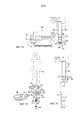
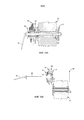
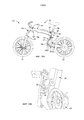
Фиг. 1 - вид сбоку примерного велосипеда.FIG. 1 is a side view of an exemplary bike.
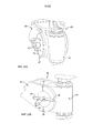
Фиг. 2A - вид спереди примерного велосипеда на фиг. 1 с педалями и рукоятками руля в примерных сложенных позициях.FIG. 2A is a front view of the exemplary bike in FIG. 1 with pedals and handlebars in the approximate folded positions.
Фиг. 2B - вид сбоку велосипеда на фиг. 2A с седлом в сложенном положении и колесами, снятыми с рамы.FIG. 2B is a side view of the bicycle in FIG. 2A with a saddle in the folded position and wheels removed from the frame.
Фиг. 2C - вид сбоку рамы велосипеда на фиг. 2B с головной трубой рамы и связанными компонентами в примерной сложенном положении.FIG. 2C is a side view of the bicycle frame in FIG. 2B with a frame head tube and associated components in an approximate folded position.
Фиг. 2D - вид сбоку рамы велосипеда на фиг. 2C с подседельной трубой рамы и пером рамы в примерных сложенных позициях.FIG. 2D is a side view of the bicycle frame in FIG. 2C with a frame seat tube and frame feather in approximate folded positions.
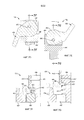
Фиг. 3 - частичный общий вид велосипеда на фиг. 1 с источником энергии, частично высвобожденным от верхней трубы рамы.FIG. 3 is a partial general view of the bicycle in FIG. 1 with an energy source partially released from the upper tube of the frame.
Фиг. 4 - общий вид примерной буксировочной конфигурации для велосипеда согласно принципам настоящего изобретения.FIG. 4 is a general view of an exemplary towing configuration for a bicycle in accordance with the principles of the present invention.
Фиг. 5A - частичный вид в поперечном разрезе вспомогательного крепежного устройства колеса для буксировочной конфигурации для велосипеда согласно принципам настоящего изобретения.FIG. 5A is a partial cross-sectional view of an auxiliary wheel mounting device for towing configuration for a bicycle in accordance with the principles of the present invention.
Фиг. 5B - частичный вид в поперечном разрезе другого вспомогательного крепежного устройства колеса для буксировочной конфигурации для велосипеда согласно принципам настоящего изобретения.FIG. 5B is a partial cross-sectional view of another auxiliary fastening device of a wheel for towing a bicycle configuration in accordance with the principles of the present invention.
Фиг. 6 - вид сверху дополнительных вспомогательных крепежных устройств колеса для буксировочной конфигурации для велосипеда согласно принципам настоящего изобретения.FIG. 6 is a top view of additional wheel anchoring devices for towing configuration for a bicycle in accordance with the principles of the present invention.
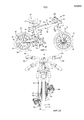
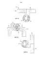
Фиг. 7A - общий вид примерного узла педали и шатуна в рабочем положении.FIG. 7A is a general view of an exemplary pedal and connecting rod assembly in the operating position.
Фиг. 7B - покомпонентный общий вид узла педали и шатуна на фиг. 7A.FIG. 7B is an exploded perspective view of the pedal and connecting rod assembly in FIG. 7A.
Фиг. 7C - вид сбоку узла педали и шатуна на фиг. 7A в сложенном положении.FIG. 7C is a side view of the pedal and connecting rod assembly in FIG. 7A in the folded position.
Фиг. 7D - частичный вид сбоку рычага и держателя для другого примерного узла педали и шатуна в заблокированной конфигурации.FIG. 7D is a partial side view of the lever and holder for another exemplary pedal and connecting rod assembly in a locked configuration.
Фиг. 7E - частичный вид сбоку рычага и держателя для узла педали и шатуна на фиг. 7D в разблокированной конфигурации.FIG. 7E is a partial side view of the lever and holder for the pedal assembly and the connecting rod in FIG. 7D in unlocked configuration.
Фиг. 7E - частичный вид в поперечном разрезе узла педали и шатуна на фиг. 7D вдоль линии 7F на фиг. 7D.FIG. 7E is a partial cross-sectional view of the pedal and connecting rod assembly in FIG. 7D along
Фиг. 7G - частичный вид в поперечном разрезе узла педали и шатуна на фиг.7E вдоль линии 7G на фиг. 7E.FIG. 7G is a partial cross-sectional view of the pedal and connecting rod assembly in FIG. 7E along
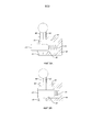
Фиг. 8A - вид сверху механизма складывания руля для велосипеда согласно принципам настоящего изобретения в рабочем положении.FIG. 8A is a top view of a bicycle folding mechanism in accordance with the principles of the present invention in a working position.
Фиг. 8B - вид сверху механизма складывания руля на фиг. 8A в сложенном положении.FIG. 8B is a top view of the steering wheel folding mechanism in FIG. 8A in the folded position.
Фиг. 8C - вид сверху механизма складывания руля на фиг. 8A в позиции для буксировочной конфигурации для велосипеда согласно принципам настоящего изобретения.FIG. 8C is a top view of the rudder folding mechanism in FIG. 8A in position for a towing configuration for a bicycle in accordance with the principles of the present invention.
Фиг. 9A - частичный вид в поперечном разрезе механизма складывания руля на фиг. 8A.FIG. 9A is a partial cross-sectional view of the rudder folding mechanism in FIG. 8A.
Фиг. 9B - другой частичный вид в поперечном разрезе механизма складывания руля на фиг. 8A.FIG. 9B is another partial cross-sectional view of the rudder folding mechanism in FIG. 8A.
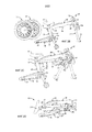
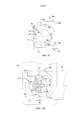
Фиг. 10A - вид в поперечном разрезе узла заднего колеса для велосипеда согласно принципам настоящего изобретения.FIG. 10A is a cross-sectional view of a bicycle rear wheel assembly in accordance with the principles of the present invention.
Фиг. 10B - вид в поперечном разрезе узла заднего колеса для велосипеда согласно принципам настоящего изобретения с задней осью и задним колесом, высвобожденными от рамы в сборе.FIG. 10B is a cross-sectional view of a rear wheel assembly for a bicycle in accordance with the principles of the present invention with the rear axle and rear wheel disengaged from the frame assembly.
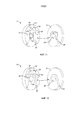
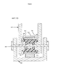
Фиг. 11 - общий вид примерного соединительного устройства колеса для велосипеда согласно принципам настоящего изобретения.FIG. 11 is a perspective view of an exemplary wheel coupling device for a bicycle in accordance with the principles of the present invention.
Фиг. 12 - общий вид другого примерного соединительного устройства колеса для велосипеда согласно принципам настоящего изобретения.FIG. 12 is a perspective view of another exemplary wheel coupling device for a bicycle in accordance with the principles of the present invention.
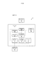
Фиг. 13 - блок-схема примерной системы питания и управления велосипеда для велосипеда согласно принципам настоящего изобретения.FIG. 13 is a block diagram of an exemplary power and control system for a bicycle for a bicycle in accordance with the principles of the present invention.
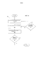
Фиг. 14 - блок-схема последовательности операций примерного процесса, который может быть реализован посредством системы питания и управления велосипеда настоящего изобретения.FIG. 14 is a flowchart of an exemplary process that may be implemented by a power and control system of a bicycle of the present invention.
Фиг. 15A - вид сбоку другого примерного велосипеда.FIG. 15A is a side view of another exemplary bike.
Фиг. 15B - общий вид участка велосипеда на фиг. 15A.FIG. 15B is a perspective view of a portion of the bicycle in FIG. 15A.
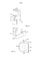
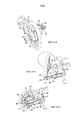
Фиг. 16 - вид сбоку примерного узла держателя и троса для шкворня рамы для велосипеда согласно принципам настоящего изобретения.FIG. 16 is a side view of an exemplary holder and cable assembly for a king pin for a bicycle in accordance with the principles of the present invention.
Фиг. 17A - вид сбоку примерного узла держателя для шкворня пера рамы для велосипеда согласно принципам настоящего изобретения.FIG. 17A is a side view of an exemplary holder assembly for a king pin of a bicycle frame in accordance with the principles of the present invention.
Фиг. 17B - вид в поперечном разрезе узла держателя на фиг. 17A.FIG. 17B is a cross-sectional view of the holder assembly in FIG. 17a.
Фиг. 18 - общий вид узла рычага и держателя шкворня и частично непокрытой подседельной трубы рамы для велосипеда согласно принципам настоящего изобретения.FIG. 18 is a general view of the lever assembly and the king pin holder and the partially uncovered seat tube of a bicycle frame in accordance with the principles of the present invention.
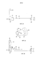
Фиг. 19 - вид сбоку другого примерного узла держателя и троса для шкворня рамы для велосипеда согласно принципам настоящего изобретения.FIG. 19 is a side view of another exemplary holder and cable assembly for a kingpin for a bicycle in accordance with the principles of the present invention.
Фиг. 20A - общий вид примерного внешнего блокирующего механизма для шкворня рамы для велосипеда согласно принципам настоящего изобретения.FIG. 20A is a perspective view of an exemplary external locking mechanism for a kingpin for a bicycle frame in accordance with the principles of the present invention.
Фиг. 20B - частичный общий вид внутренних элементов блокирующего механизма на фиг. 20A.FIG. 20B is a partial general view of the internal components of the locking mechanism in FIG. 20a.
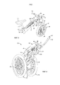
Фиг. 21A - общий вид примерного компонента пера рамы, поворачивающего заднее колесо на первой петле из конфигурации для верховой езды на фиг. 15.FIG. 21A is a perspective view of an exemplary pen component of a frame turning a rear wheel on a first loop of a riding configuration in FIG. 15.
Фиг. 21B - общий вид компонента пера рамы на фиг. 21A, поворачивающего заднее колесо на второй петле.FIG. 21B is a perspective view of the pen component of the frame in FIG. 21A turning the rear wheel on the second loop.
Фиг. 21C - общий вид компонента пера рамы на фиг. 21A-B, располагающего заднее колесо во вспомогательном положении, по существу по оси совмещенной со вспомогательным установочным устройством колеса для переднего колеса.FIG. 21C is a perspective view of a component of a frame pen in FIG. 21A-B, having the rear wheel in an auxiliary position, substantially axially aligned with the auxiliary wheel alignment device for the front wheel.
Фиг. 22 - общий вид примерного соединительного устройства колеса для компонента пера рамы для велосипеда согласно принципам настоящего изобретения.FIG. 22 is a perspective view of an exemplary wheel coupling device for a bike frame feather component in accordance with the principles of the present invention.
Фиг. 23 - частичный верхний вид в поперечном разрезе примерного компонента пера рамы, имеющего поворотный рычаг, располагающий заднее колесо в конфигурации для езды верхом на фиг. 15.FIG. 23 is a partial upper cross-sectional view of an exemplary component of a frame pen having a pivot arm positioning a rear wheel in a horse riding configuration in FIG. 15.
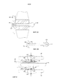
Фиг. 24 - вид сбоку примерного узла оси колеса для велосипеда согласно принципам настоящего изобретения.FIG. 24 is a side view of an exemplary wheel axle assembly for a bicycle in accordance with the principles of the present invention.
Фиг. 25 - общий вид примерного компонента основания для узла колесной оси на фиг. 24.FIG. 25 is a perspective view of an exemplary base component for a wheel axle assembly in FIG. 24
Фиг. 26 - вид сбоку узла колесной оси на фиг. 24 с вспомогательным рычажком, присоединенным к нему.FIG. 26 is a side view of the axle assembly of FIG. 24 with auxiliary lever attached to it.
Фиг. 27A - частичный вид в разрезе первоначального взаимодействия компонентов основания и основной части узла колесной оси на фиг. 24.FIG. 27A is a partial sectional view of the initial interaction of the base components and the main body of the wheel axle assembly in FIG. 24
Фиг. 27B - частичный вид в разрезе взаимодействия компонента основания и байонетного компонента узла колесной оси на фиг. 24.FIG. 27B is a partial sectional view of the interaction of the base component and the bayonet component of the wheel axle assembly in FIG. 24
Фиг. 27C - частичный вид в поперечном разрезе поворота рычажка узла колесной оси на фиг. 24, имеющего взаимодействие компонента основания и байонетного компонента на фиг. 27B.FIG. 27C is a partial cross-sectional view of the rotation of the lever of the wheel axle assembly in FIG. 24 having the interaction of the base component and the bayonet component in FIG. 27b.
Фиг. 27D - частичный вид в поперечном разрезе дальнейшего поворота рычажка узла колесной оси на фиг. 24, имеющего компонент основания и байонетного компонента сцепления вала на фиг. 27B для напряжения основной части.FIG. 27D is a partial cross-sectional view of the further rotation of the lever of the wheel axle assembly in FIG. 24 having a base component and a bayonet coupling component of the shaft in FIG. 27B for the voltage of the main part.
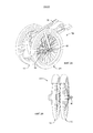
Фиг. 28 - общий вид другой примерной буксировочной конфигурации для велосипеда согласно принципам настоящего изобретения.FIG. 28 is a perspective view of another exemplary towing configuration for a bicycle in accordance with the principles of the present invention.
Фиг. 29 - общий вид переднего и заднего колес для велосипеда согласно принципам настоящего изобретения, соединенных вместе для хранения.FIG. 29 is a general view of the front and rear wheels for a bicycle in accordance with the principles of the present invention, joined together for storage.
ОПИСАНИЕ ПРЕДПОЧТИТЕЛЬНЫХ ВАРИАНТОВ ОСУЩЕСТВЛЕНИЯ ИЗОБРЕТЕНИЯDESCRIPTION of the PREFERRED EMBODIMENTS of the INVENTION
ОБЗОРOVERVIEW
Примерный велосипед согласно настоящему изобретению имеет складную раму, с которой колеса могут быть сняты или повторно установлены для реконфигурации и/или для хранения рамы. Сложенная рама помещается внутри багажного отсека типичного пассажирского автомобиля, минимизируя потерю емкости багажного отсека и, если колеса сняты, вес для подъема. Примерный велосипед может включать в себя систему питания и управления, включающую в себя компьютер и устройства ввода данных для измерения, например, физиологических факторов пользователя и управления мотором согласно характеристикам пользователя. Примерный велосипед может быть выполнен в буксировочной конфигурации с колесами, повторно присоединенными и/или повторно спозиционированными на сложенной раме, чтобы предоставлять возможность пользователю тянуть велосипед, и любое прикрепление к нему (например, багаж). В реализациях, включающих в себя систему питания и управления, мотор может быть приведен в действие в буксировочной конфигурации, чтобы помогать в буксировке сложенного велосипеда. Примерный велосипед может также включать в себя складные крепежные устройства педалей и руля, компонент складывания пера рамы, два или более шкворней рамы, соединенных вместе на одном блокирующем рычажке, и соединительные устройства колес и колесные оси, раскрытые в данном документе. Примерный велосипед может также быть совместим со стандартными в велосипедной промышленности компонентами, такими как педали, тормозные рычаги, переключатели передач, рукоятки, узлы передней вилки, колеса, подшипники рулевой колонки, свободновращающиеся втулки, системы ведущих звездочек и кассеты звездочек.An exemplary bicycle according to the present invention has a folding frame from which the wheels can be removed or re-mounted for reconfiguration and / or for storing the frame. The folded frame is placed inside the luggage compartment of a typical passenger car, minimizing the loss of capacity of the luggage compartment and, if wheels are removed, weight for lifting. An exemplary bike may include a power and control system that includes a computer and input devices for measuring, for example, the physiological factors of the user and controlling the motor according to the characteristics of the user. An exemplary bike may be made in a towing configuration with wheels reattached and / or re-positioned on the folded frame to allow the user to pull the bike and any attachment to it (for example, luggage). In implementations that include a power and control system, the motor can be powered in a towing configuration to assist in towing a folded bicycle. An exemplary bike may also include folding pedal and handlebar anchors, a folding frame feather component, two or more frame pivots connected together on one locking lever, and wheel coupling devices and wheel axles disclosed in this document. An exemplary bike may also be compatible with standard components in the bicycle industry, such as pedals, brake levers, gearshift paddles, handles, front fork assemblies, wheels, steering column bearings, freewheel sleeves, drive sprocket systems and sprocket cassettes.
ЭЛЕМЕНТЫ ПРИМЕРНОГО ВЕЛОСИПЕДАELEMENTS OF THE EXAMPLE BIKE
Фиг. 1 - вид сбоку примерного велосипеда 100. Следует понимать, что, пока иное не утверждается в данном документе, раскрытие всех компонентов велосипедов согласно принципам настоящего изобретения может быть применимо к каждому примерному велосипеду или подсистеме велосипеда, подузлу, участку, секции или механизму, соответственно.FIG. 1 is a side view of an
Велосипед 100 включает в себя переднее колесо 110 и заднее колесо 112. Переднее и заднее колеса 110, 112 присоединены с возможностью вращения к раме 120 в сборе, также называемой в данном документе рамой.The
Рама 120 в сборе и переднее колесо 110 избирательно сцепляются на трубе 122 передней вилки. Труба 122 передней вилки соединяется с головной трубой 124 рамы. Рама 120 в сборе дополнительно включает в себя верхнюю трубу 126 рамы, соединенную с головной трубой 124 рамы, подседельная труба 128 рамы соединяется с верхней трубой 126 рамы напротив головной трубы 124 рамы, и нижнюю заднюю вилку 130, соединенную с подседельной трубой 128 рамы. Головная труба 124 рамы соединяется с верхней трубой 126 рамы близко к переднему концу 132 верхней трубы 126 рамы, и, близко к противоположному заднему концу 134 верхней трубы 126 рамы, верхний конец 136 подседельной трубы 128 соединяется с верхней трубой 126 рамы. На нижнем конце 138 подседельной трубы 128 рамы к ней присоединяется сторона 140 педалей пера 130 рамы. Заднее колесо 112 соединяется с противоположной колесной стороной 142 пера 130 рамы. Компоненты рамы 120 в сборе могут включать в себя материалы, такие как, например, волоконные полимерные композиты, сталь, титановые и алюминиевые сплавы.The assembled
В одной реализации рама 120 в сборе велосипеда 100 включает в себя первый рычажок 144 рамы, соединенный с верхней трубой 126 рамы, и второй и третий рычажки 146, 148 рамы, соединенные с подседельной трубой 128 рамы. Первый рычажок 144 рамы избирательно фиксирует головную трубу 124 рамы относительно верхней трубы 126 рамы вокруг первого шкворня 150 рамы; второй рычажок 146 рамы избирательно фиксирует подседельную трубу 128 рамы относительно верхней трубы 126 рамы вокруг второго шкворня 152 рамы, и третий рычажок 148 рамы избирательно фиксирует нижнюю заднюю вилку 130 относительно подседельной трубы 128 рамы вокруг третьего шкворня 154 рамы. Шкворни 150, 152, 154 могут быть ориентированы по существу параллельно друг другу. В другом примере, согласно принципам настоящего изобретения, рама 120 может быть зафиксирована так, как описано в данном документе относительно рамы 620 велосипеда 600 и фиг. 15-20. Соответственно, велосипед согласно принципам настоящего изобретения и/или его компоненты могут быть избирательно выполнены, например, для вертикальной работы (фиг. 1, фиг. 15), хранения (фиг. 2D, фиг. 29) и буксировки (фиг. 4, фиг. 28).In one implementation, the
Велосипед 100 может также включать в себя компонент 156 подвески, соединенный между трубой 122 передней вилки и передним колесом 110. Компонент 156 подвески может быть гидравлическим механизмом подвески. Дополнительно, велосипед 100 включает в себя тормозные механизмы (не показаны), функционально соединенные с каждым из переднего и заднего колес 110, 112. Тормозные механизмы могут быть, например, гидравлическими дисковыми тормозными механизмами или тормозными механизмами, действующими на обод колеса.
Со ссылкой на фиг. 2A в дополнение к фиг. 1, велосипед 110 включает в себя педальный узел или систему 160 ведущих звездочек, соединенную с подседельной трубой 128 рамы близко к ее нижнему концу 138. Система 160 ведущих звездочек включает в себя пару шатунов 162a, 162b, соединенных к противоположным концам оси 164 педали или каретки. Педали 166a, 166b соединяются с концами шатунов 162a, 162b, соответственно, напротив оси 164 каретки. Педали 166a, 166b взаимодействуют с механизмами 170a, 170b крепления педалей, соответственно. Как описано в данном документе относительно фиг. 7A-7G, механизмы 170a, 170b крепления педалей избирательно задействуются, чтобы поворачивать педали 166a, 166b, соответственно, между рабочими положениями, по существу ортогональными соответствующим шатунам 162a, 162b (фиг. 1), и сложенными положениями, совмещенными с соответствующими шатунами 162a, 162b (фиг. 2A-2D), в помощь избирательному конфигурированию велосипеда 100, например, для вертикальной работы (фиг. 1), хранения (фиг. 2D) и буксировки (фиг. 4).Referring to FIG. 2A in addition to FIG. 1,
С продолжающейся ссылкой на фиг. 1, велосипед 100 включает в себя передаточный узел 180, соединенный между системой 160 ведущих звездочек и задним колесом 112. Передаточный узел 180 включает в себя переднюю звездочку 182, прикрепленную к оси 164 каретки, кассету 184 задних звездочек, соединенную с задним колесом 112, и цепь 186, продолжающуюся между передней звездочкой 182 и кассетой 184 задних звездочек. С велосипедом 100, выполненным для вертикальной работы (фиг. 1), шатуны 162a, 162b и ось 164 каретки переводят усилие, прикладываемое, чтобы крутить педали 166a, 166b, в привод передней звездочки 182, которая, в свою очередь, приводит в движение заднее колесо 112 через цепь 186 и кассету 184 задних звездочек. В других реализациях велосипед согласно принципам настоящего изобретения может включать в себя механизм переключения передач с компонентами, соединенными с пером рамы и/или подседельной трубой рамы, чтобы обеспечивать многоступенчатую передачу.With continued reference to FIG. 1,
Велосипед 100 включает в себя вынос 190 руля, продолжающийся относительно вверх от головной трубы 124 рамы противоположно трубе 122 передней вилки, при этом велосипед 100 находится в вертикальной конфигурации, иллюстрированной на фиг. 1. Вынос 190 руля поддерживает механизм 192 складывания руля и рукоятки 194a, 194b, присоединенные на противоположных сторонах механизма 192 складывания руля. Как описано в данном документе относительно фиг. 8A-8C и 9A-9B, механизм 192 складывания руля избирательно задействуется, чтобы поворачивать рукоятки 194a, 194b между рабочими положениями, по существу ортогональными выносу 190 руля и головной трубе 124 рамы (например, фиг. 1), и сложенными положениями, совмещенными с выносом 190 руля и головной трубой 124 рамы (например, фиг. 2A-2D), в помощь избирательному конфигурированию велосипеда 100, например, для вертикальной работы (фиг. 1), хранения (фиг. 2D) и буксировки (фиг. 4). Велосипед 100 может включать в себя компоненты руля, такие как ручки 196a, 196b тормоза, соответственно присоединенные к рукояткам 194a, 194b.
С продолжающейся ссылкой на фиг. 1, велосипед 100 включает в себя седло 210, поддерживаемое посредством подседельного штыря 212, телескопически принимаемого в подседельную трубу 128 рамы. Велосипед 100 дополнительно включает в себя механизм 214 фиксации подседельного штыря, такой как избирательно задействуемый хомут или шплинт. Соответственно, седло 210 может регулироваться относительно рамы 120 в сборе и системы 160 ведущих звездочек для комфорта и размера пользователя велосипеда 100. Кроме того, седло 210 может быть расположено близко к верхнему концу 136 подседельной трубы 128 рамы в помощь избирательному конфигурированию велосипеда 100, например, для хранения (фиг. 2D) и буксировки (фиг. 4).With continued reference to FIG. 1, the
Переднее колесо 110 зацепляет трубу 122 передней вилки посредством передней оси 230 и одного из соединительных устройств 510 (например, фиг. 11). Передняя ось 230 включает в себя высвобождающую ручку 232 на ней, и высвобождающая ручка 232 может быть задействована, чтобы временно снимать переднюю ось 232, чтобы предоставлять возможность снятия переднего колеса 110 с трубы 122 передней вилки в помощь избирательному конфигурированию велосипеда 100, например, для хранения (фиг. 2D) и буксировки (фиг. 4). Переднее колесо 110 дополнительно включает в себя щиток 234 и шину 236.The
Заднее колесо 112 сцепляется с пером 130 рамы посредством задней оси 240 (фиг. 6) и одного из соединительных устройств 510 (например, фиг. 11). Задняя ось 240 включает в себя высвобождающую ручку 242 на ней, и высвобождающая ручка 242 может быть задействована, чтобы временно снимать заднюю ось 240, чтобы предоставлять возможность снятия заднего колеса 112 с пера 130 рамы в помощь избирательному конфигурированию велосипеда 100, например, для хранения (фиг. 2D) и буксировки (фиг. 4). Заднее колесо 112 дополнительно включает в себя щиток 244 и шину 246.The
ПРИМЕРНОЕ СКЛАДЫВАНИЕ РАМЫSAMPLE FOLDING FRAME
Фиг. 2A - передний вид велосипеда 100. Чтобы складывать велосипед 100 из вертикальной конфигурации на фиг. 1 в конфигурацию для хранения на фиг.2D, педали 166a, 166b поворачиваются из рабочих позиций, по существу ортогональных соответствующим шатунам 162a, 162b, в сложенные позиции, совмещенные с соответствующими шатунами 162a, 162b, посредством действия механизмов 170a, 170b крепления педалей, соответственно. Компоненты и работа механизмов 170a, 170b крепления педалей описаны более подробно в данном документе со ссылкой на фиг. 7A-7G. Аналогично, рукоятки 194a, 194b поворачиваются из рабочих позиций, по существу ортогональных выносу 190 руля и головной трубе 124 рамы, в сложенные позиции, совмещенные с выносом 190 руля и головной трубой 124 рамы, посредством действия механизма 192 складывания руля. Компоненты и работа механизма 192 складывания руля описываются в дополнительных деталях в данном документе относительно фиг. 8A-8C и 9A-9B.FIG. 2A is a front view of the
Фиг. 2B - вид сбоку рамы 120 в сборе велосипеда 100 со снятыми передним и задним колесами 110, 112. В частности, высвобождающие ручки 232, 242 были задействованы, чтобы временно снимать переднюю и заднюю оси 230, 240, и переднее и заднее колеса 110, 112 были отсоединены от трубы 122 передней вилки и пера 130 рамы, соответственно. Переднее и заднее колеса 110, 112 могут храниться отдельно от рамы 120 в сборе. Передняя и задняя оси 230, 240 могут быть повторно присоединены к раме 120 в сборе для хранения на ней.FIG. 2B is a side view of the
Фиг. 2C - вид сбоку рамы 120 в сборе велосипеда 100 с головной трубой 126 рамы в примерной сложенной или предназначенной для хранения позиции. Чтобы складывать головную трубу 124 рамы и компоненты, присоединенные к ней – трубу 122 передней вилки, вынос 190 руля, механизм 192 складывания руля и рукоятки 194a, 194b – относительно верхней трубы 126 рамы, первый рычажок 144 рамы может быть избирательно задействован, чтобы поворотным образом разблокировать головную трубу 124 рамы относительно верхней трубы 126 рамы, и головная труба 124 рамы может быть повернута вокруг первого шкворня 150 рамы так, что труба 122 передней вилки накладывается на верхнюю трубу 126 рамы.FIG. 2C is a side view of
Фиг. 2D - вид сбоку рамы 120 в сборе велосипеда 100 в конфигурации для хранения с подседельной трубой 124 рамы и пером 130 рамы, также в примерных сложенных или предназначенных для хранения позициях. В этой примерной реализации, чтобы складывать подседельную трубу 128 рамы и компоненты, присоединенные к ней, относительно верхней трубы 126 рамы, второй рычажок 146 рамы может быть избирательно задействован, чтобы поворотным образом разблокировать подседельную трубу 128 рамы относительно верхней трубы 126 рамы, и подседельная труба 128 рамы может быть повернута вокруг второго шкворня 152 рамы так, что подседельная труба рамы располагается под верхней трубой 126 рамы и трубой 122 передней вилки. Чтобы складывать нижнюю заднюю вилку 130 и компоненты, присоединенные к ней, относительно подседельной трубы 128 рамы, третий рычажок 148 рамы может быть избирательно задействован, чтобы вращательным образом разблокировать нижнюю заднюю вилку 130 относительно подседельной трубы 128 рамы, и перо 130 рамы может быть повернута вокруг третьего шкворня 154 рамы так, что перо 130 рамы располагается вдоль подседельной трубы 128 рамы. Третий шкворень 154 рамы расположен с интервалом от оси 164 каретки, так что, когда колесная сторона 142 пера 130 рамы поворачивается к верхнему концу подседельной трубы 128 рамы, кассета 184 задних звездочек передаточного узла 180 перемещается ближе к передней звездочке 182. По существу, цепь 186 становится ослабленной (фиг. 2D) и не препятствует складыванию рамы 120 в сборе. Следует понимать, что для того, чтобы установить велосипед 100 в вертикальной конфигурации (например, фиг. 1), эти этапы могут быть проделаны в обратном направлении. Также следует понимать, что эта процедура может изменяться согласно конкретным компонентам, применяемым в велосипеде, например, механизму блокировки множества шкворней рамы, раскрытому относительно велосипеда 600 и фиг. 15-20.FIG. 2D is a side view of the
С рамой 120 в сборе велосипеда 100 в сложенной или предназначенной для хранения конфигурации на фиг. 2D рама 120 в сборе может храниться во множестве мест, например, багажном отсеке компактного автомобиля или под рабочим столом в офисе. В некоторых реализациях каждый из механизмов для складывания велосипеда 100 из вертикальной, рабочей конфигурации в сложенную, предназначенную для хранения конфигурацию – например, первый, второй и третий рычажки 144, 146, 148 рамы; механизмы 170a, 170b крепления педалей; механизм 192 складывания руля; механизм 214 фиксации подседельного штыря; и передняя и задняя высвобождающие ручки 232, 242 для передней и задней осей 230, 240, соответственно – каждая может быть задействована вручную, например, без использования каких-либо дополнительных инструментов. Соответственно, велосипед 100 может быть относительно быстро сложен или разложен, например, некоторыми пользователями, менее чем за 60 секунд, предоставляя удобный вариант для транспортировки велосипеда 100, например, в пешеходных зонах, общественном транспорте и/или пассажирских транспортных средствах.With
В некоторых реализациях велосипед 100 согласно настоящему изобретению включает в себя систему 250 питания и управления (фиг. 13) для избирательного предоставления энергии для движения, помощи в предоставлении энергии для движения и/или обеспечения контроля и управления велосипедом 100. Обращаясь к фиг. 3, система 250 питания и управления для велосипеда 100 может включать в себя источник 260 энергии, например, перезаряжаемую аккумуляторную батарею, поддерживаемую в верхней трубе 126 рамы. В одном примере, источник 260 энергии может быть 36 вольтовой, емкостью 8 ампер-часов аккумуляторной батарей, включающей в себя модуль из 40 литиево-ионных аккумуляторных элементов типа «AA» емкостью 2,2 ампер-часов. Верхняя труба 126 рамы может включать в себя опорный рычаг 262 для крепления источника 260 энергии и предоставления доступа к нему для пользователя велосипеда 100. Опорный рычаг 262 является дополняющим желобок 264 в верхней трубе 126 рамы, чтобы принимать и закреплять источник 260 энергии и опорный рычаг 262. Опорный рычаг 262 может быть выполнен так, что в сложенной конфигурации рамы 120 опорный рычаг 262 находится в или рядом с центром тяжести сложенной рамы 120 и предоставляет ручку для переноски сложенной рамы 120 (см. например, фиг. 2D).In some implementations, the
Велосипед 100 может дополнительно включать в себя панель 270 управления, чтобы предоставлять пользовательский интерфейс для системы 250 питания и управления. Как иллюстрировано на фиг. 3, примерная панель 270 управления может включать в себя крепление 272 устройства управления и пользовательское устройство 274. Крепление 72 и пользовательское устройство 274, присоединенное к нему, электрически соединены с источником 260 энергии. Следует понимать, что пользовательское устройство 274 может быть любым устройством из множества установленных и/или съемных вычислительных устройств, включающих в себя процессор и память, а также функциональные возможности связи. Например, пользовательское устройство 274 может быть переносным компьютером, планшетным компьютером, смартфоном и т.д., который включает в себя функциональные возможности для беспроводной связи посредством IEEE 802.11, Bluetooth и/или протоколов сотовой связи. Дополнительно, пользовательское устройство 274 может использовать такие функциональные возможности связи, чтобы связываться по сети, например, посредством различных проводных и/или беспроводных технологий сетевого взаимодействия, например, по сотовым сетям, Bluetooth-сетям, проводным и/или беспроводным сетям с коммутацией пакетов и т.д. Соответственно, пользовательское устройство 274 может быть использовано, чтобы выполнять операции, такие как функции распознавания голоса, камеры, функции системы глобального позиционирования (GPS) и т.д.
Система 250 питания и управления велосипеда 100 может также включать в себя мотор 280, присоединенный и поддерживаемый посредством заднего колеса 112. Например, мотор 280 может быть снабжаемым электроэнергией 250- или 350-ваттным бесщеточным электромотором постоянного тока на ступице колеса. Мотор 280 электрически соединен с источником 260 энергии.The power and
С дополнительной ссылкой на схематичную иллюстрацию системы 250 питания и управления велосипеда 100 на фиг.13, система 250 питания и управления может включать в себя компьютер или микроконтроллер 282, включающий в себя процессор и память, память включает в себя одну или более форм компьютерно-читаемых носителей и хранит инструкции, исполняемые процессором для выполнения различных операций, включающих в себя раскрытые в данном документе. Дополнительно, компьютер 282 может включать в себя более одного вычислительного устройства, например, контроллеры или т.п., включенные в велосипед 100 для наблюдения и/или управления различными компонентами. Компьютер 282, как правило, выполнен для связи по шине локальной сети контроллеров (CAN) или т.п. Через CAN-шину и/или другие проводные или беспроводные механизмы компьютер 282 может передавать сообщения различным устройствам в велосипеде и/или принимать сообщения от различных устройств, например, контроллеров, актуаторов, датчиков и т.д. Альтернативно или дополнительно, в случаях, когда компьютер 282 фактически содержит множество устройств, CAN-шина или т.п. может быть использована для связи между устройствами, представленными как компьютер 282 в этом изобретении. Кроме того, компьютер 282 может быть выполнен для связи с сетью, которая может включать в себя различные проводные и/или беспроводные технологии сетевого взаимодействия, например, сотовые, Bluetooth, проводные и/или беспроводные сети с коммутацией пакетов и т.д.With further reference to a schematic illustration of the power and
Система 250 питания и управления включает в себя контроллер 284 мотора в соединении с компьютером 282 для управления мотором 280 велосипеда 100. Компьютер 282 выполнен с возможностью приема информации от пользовательского устройства 274 через крепление 272 и/или элементы 286 управления на руле, поддерживаемые на одной или более рукоятках 194a, 194b. Пользовательское устройство 274 и/или элементы 286 управления на руле могут включать в себя электромеханические интерфейсы, такие как кнопки – такие как вытяжная кнопка 402 рукоятки 194a, описанной в данном документе относительно фиг.3, круглые ручки и дисковые регуляторы, а также другие интерфейсы человек-машина, такие как интерактивная система распознавания голоса, графический пользовательский интерфейс (GUI), включающий в себя сенсорный экран или т.п., и т.д.The power and
Компьютер 282 также выполнен с возможностью приема информации от одного или более датчиков 288, относящихся к различным компонентам или состояниям велосипеда 100, например, датчика близости для обнаружения другого расположенного поблизости транспортного средства и каденционного и моментного датчика для кручения педалей пользователем, такого как, в качестве неограничивающего примера, измеряющая темп и крутящий момент каретка. Датчики 288 могут также включать в себя компоненты, такие как датчики скорости и углового положения заднего колеса, такие как датчик на эффекте Холла, встроенный в мотор 280, датчики потребления тока и/или напряжения мотором 280, датчик близости транспортного средства, датчики температуры и уровня мощности аккумулятора. Датчики 288 находятся в соединении с компьютером 282 и электрически соединены с источником 260 энергии. Дополнительно, датчики 288 могут включать в себя оборудование системы глобального позиционирования (GPS) и т.д., чтобы предоставлять данные непосредственно компьютеру 282, например через проводное или беспроводное соединение. Датчики 288 могут включать в себя устройства связи, чтобы отправлять и принимать информацию от других транспортных средств, такую как близость и скорость. В других примерах датчики 288 могут включать в себя механизмы, такие как RADAR, LADAR, сонар и т.д., датчики, которые могут применяться, чтобы измерять расстояние между велосипедом 100 и другими транспортными средствами или объектами. Еще одни датчики 288 могут включать в себя камеры, датчики движения или другие механизмы, чтобы обнаруживать позицию, изменение в позиции, скорость изменения в позиции и т.д. велосипеда 100 или его компонентов. Память компьютера 282, в целом, хранит данные, собранные с датчиков 288.
Система 250 может дополнительно включать в себя один или более фонарей 290 в соединении с компьютером 282 и электрически соединенных с источником 260 энергии, таких как передняя фара, задние фонари 291 (фиг. 3), сигналы поворота и передний и задний периферийные лампы направленного света. Например, когда управляются посредством компьютера 282, периферийные лампы направленного света могут проецировать освещенную границу вокруг велосипеда 100 во время работы, чтобы сообщать безопасную дистанцию для других транспортных средств. В другом примере компьютер 282 может активировать задние фонари 292 при нажатии одной из ручек 196a, 196b тормоза. Система 250 дополнительно выполнена, чтобы подключаться к зарядным устройствам 292 для перезарядки источника 260 энергии, включающим в себя зарядные устройства, приспособленные для использования в зданиях, на зарядных станциях и/или автомобилях, и/или зарядные устройства, независимо генерирующие электроэнергию, например, солнечные элементы.
В некоторых примерах элементы системы, например, для системы 250 питания и управления велосипеда 100, могут быть реализованы как компьютерно-читаемые инструкции (например, программное обеспечение) на одном или более вычислительных устройствах (например, серверах, персональных компьютерах и т.д.), сохраненные на считываемых компьютером носителях, связанных с ним (например, дисках, запоминающих устройствах и т.д.). Компьютерный программный продукт может содержать такие инструкции, сохраненные на считываемых компьютером носителях, для выполнения функций, описанных в данном документе.In some examples, elements of the system, for example, for the power and
ПРИМЕРНАЯ ПОСЛЕДОВАТЕЛЬНОСТЬ ОПЕРАЦИЙ ПРОЦЕССАEXAMPLE SEQUENCE OF PROCESS OPERATIONS
Фиг. 14 является схемой примерного процесса 300 для компьютера 282, чтобы управлять различными компонентами и/или операциями велосипеда 100, чтобы оптимизировать усилия пользователя или помогать пользователю в некоторых ситуациях на основе данных, принятых, например, от пользовательского устройства 274, элементов 286 управления на руле и/или датчиков 288. Например, на основе характеристик пользователя, таких как физиологические и биометрические факторы, введенные пользователем, образованные посредством компьютера 282, например, посредством выполнения инструкций процесса калибровки для процедуры калибровки, сохраненных в памяти, и/или измеренные посредством датчиков 288 и сохраненные в памяти компьютера 282, вместе с инструкциями, алгоритмами, программами и уравнениями, сохраненными в памяти компьютера 282, компьютер 282 велосипеда 100 может определять выходную мощность электромотора и предоставлять функции, такие как помогающие усилия при запуске на перекрестке и/или при подъеме в гору, оптимизацию темпа кручения педалей и оптимизацию диапазона уклона велосипеда.FIG. 14 is a diagram of an
Примерный процесс 300 начинается в блоке 310, в котором характеристики пользователя измеряются и/или обновляются посредством компьютера 282, датчиков 288, пользовательского устройства 274 и/или элементов 286 управления на руле и сохраняются в памяти компьютера 282. Характеристики пользователя могут включать в себя, например, физиологические и биометрические факторы, такие как мощность кручения педалей, усилие для кручения педалей, темп кручения педалей, вес, уровень комфорта, мастерство верховой езды, аэродинамическая форма, одежда и уровень физической подготовки. В одном примере, чтобы измерять характеристики пользователя для усилия кручения педалей и темпа кручения педалей, компьютер 282 может включать в себя программное обеспечение или инструкции для заданного теста или процесса калибровки или режима, в котором эти факторы непосредственно измеряются (например, темп кручения педалей) и/или определяются (например, усилие кручения педалей как функция приложенного крутящего момента). В такой примерной реализации измеренные значения производительности пользователя, например, темпа кручения педалей и крутящего момента от кручения педалей, могут быть расположены и сохранены посредством компьютера 282 через заполнение одного или более массивов данных в его памяти, для каждой предписанной автоматизированной последовательности калибровки, также сохраненной в его памяти. Характеристики пользователя могут быть вычислены из одного или более массивов данных. В другом примере пользователь может вводить или предоставлять характеристики пользователя через пользовательское устройство 274 и/или элементы 286 управления на руле, через ручной ввод или через сохраненное измерение или образование характеристик пользователя посредством другого программного обеспечения, механизмов или машин (например, велотренажера или другого тренажерного оборудования). Еще одни характеристики пользователя могут быть непосредственно измерены, такие как вес. В другом примере характеристики пользователя могли быть ранее сохранены в памяти компьютера 282, и велосипед обновляет характеристики пользователя на основе показателей работы велосипеда 100 или нового теста или работы в режиме калибровки.The
С определенными характеристиками пользователя процесс продолжается в блоке 320, в котором компьютер 282 определяет энергетический вклад от мотора 280 для рабочего состояния велосипеда 100, например, уклона пути, текущей скорости и/или близости велосипеда 100 к другим транспортным средствам, которые могут быть измерены посредством датчиков 288. Например, если велосипед 100 выполнен, чтобы предоставлять мощностное содействие во время ускорения на перекрестках, чтобы помогать пользователю не допускать замедления дорожного движения, велосипед 100 может идентифицировать событие ускорения из измеренной скорости ниже конкретного сохраненного порогового значения, и когда измеренный темп кручения педалей и/или мощность выше некоторых пороговых значений. С характеристиками пользователя, такими как вес, сила кручения педалей и темп кручения педалей, компьютер 282 может определять операционные параметры и/или инструкции для контроллера 284 мотора, чтобы активизировать мотор 280 и предоставлять возможность работы велосипеда 100 в пределах характеристик пользователя и других параметров, таких как пороговые значения управления и данные от датчиков 288, сохраненные в памяти компьютера 282. Пороговые значения управления могут включать в себя, например, пороговые значения безопасности, такие как максимальная скорость или угол велосипеда, или пороговые значения комфорта, такие как максимальная сила кручения педалей или темп ускорения.With certain user characteristics, the process continues at
Посредством заданных инструкций для управления мотором 280 далее, в блоке 330, компьютер 282 и/или контроллер 284 мотора управляют мотором 280 согласно инструкциям. В блоке 340 компьютер 282 определяет, должны ли функции управления продолжаться, например, может ли велосипед 100 достичь своего пункта назначения. Если управление компьютера 282 не должно продолжаться, например, велосипед достиг своего пункта назначения и/или выключен, процесс 300 заканчивается. Если управление продолжается, процесс 300 продолжается в блоке 350, в котором компьютер 282 определяет, должны ли характеристики пользователя быть обновлены. Если характеристики пользователя должны быть обновлены, например, компьютер 282 работает в фитнесс-режиме, предназначенном, чтобы регулировать энергетический уровень пользователя, процесс 300 возвращается к блоку 310. Если характеристики пользователя не должны быть обновлены, например, компьютер 282 работает в режиме сбережения сил, основанном на статических характеристиках пользователя, таких как вес пользователя, процесс 300 возвращается к блоку 320.Through predetermined instructions for controlling the
В одной примерной реализации компьютер 282 может оптимизировать диапазон работы аккумулятора посредством процесса 300, например, компьютер 282 может постоянно обновлять характеристики пользователя, чтобы повторно оптимизировать подачу энергии для того, чтобы максимизировать эксплуатационную характеристику велосипеда. В других реализациях велосипед 100 и компьютер 282 могут предоставлять возможность пользователю определять степень, до которой компьютер 282 полагается на характеристики пользователя, чтобы определять инструкции для работы мотора 280 в данном рабочем режиме. В дополнительных примерах рабочие режимы могут иметь различные целевые результаты, такие как: режим обучения, когда инструкции для работы мотора 280 определяются согласно пользовательскому обучению или требованиям к физической форме; режим автоматического поддержания скорости движения, когда скорость, вводимая, например, через элементы 286 управления на руле, поддерживается на всем протяжении изменяющихся условий пути; режимы форсирования ускорения, когда энергия предоставляется, например, на перекрестках или холмах, чтобы уменьшать время ускорения и/или усилие; режимы оптимизации кручения педалей, когда вспомогательная энергия регулируется так, что велосипедист может поддерживать предварительно заданный или измеренный оптимальный темп или энергию кручения педалей; рекуперативная подзарядка, когда система 250 питания и управления и/или мотор 280 включают в себя механизмы рекуперативной мощности, чтобы перезаряжать источник 260 энергии на спусках или во время замедления; и режим гарантирования дальности действия, когда предварительно заданный или измеренный пункт назначения вводится, и велосипед оптимизирует эксплуатационную характеристику, чтобы гарантировать, что дальность действия источника 260 энергии продляется до пункта назначения. В другом примере рабочие режимы могут быть предварительно образованы, чтобы приспосабливать эксплуатационную характеристику велосипеда 100 к конкретному стилю, например, более быстрому ускорению при «спортивной» регулировке в любом подходящем режиме работы. По существу, примерный процесс 300 может предоставлять множество темпов кручения педалей без необходимости индивидуально приспосабливать зубчатую передачу велосипеда 100.In one exemplary implementation,
ПРИМЕРНАЯ БУКСИРОВОЧНАЯ КОНФИГУРАЦИЯEXAMPLE TOWING CONFIGURATION
Со ссылкой на фиг. 4, в одной реализации, велосипед 100 может быть расположен в буксировочной конфигурации 400. В буксировочной конфигурации 400 переднее и заднее колеса 110, 112 повторно позиционируются на раме 120 в сборе, и труба 122 передней вилки, головная труба 124 рамы, подседельная труба 128 рамы, перо 130 рамы и педали 166a, 166b каждая складываются, как описано в данном документе относительно фиг. 2A-2D. Как описано в дополнительных деталях в данном документе относительно фиг. 8A-8C и 9A-9B, рукоятки 194a, 194b поворачиваются в позицию буксировки, иллюстрированную на фиг. 4. В частности, рукоятка 194b складывается вдоль головной трубы 124 рамы, а рукоятка 194a протягивается в противоположном направлении, от головной трубы 124 рамы и верхней трубы 126 рамы. Рукоятка 194a включает в себя компонент интерфейса, такой как кнопка 402 буксировки на своем конце, чтобы предоставлять пользователю возможность активации системы 250 питания и управления в буксировочной конфигурации руля.Referring to FIG. 4, in one implementation, the
В одной реализации переднее и заднее колеса 110, 112 повторно позиционируются на сложенной раме 120 в сборе посредством вспомогательных крепежных устройств 410a (фиг. 5A) и 410b (не показано) колес. Следует понимать, что описание в данном документе одного из вспомогательных крепежных устройств 410a, 410b колес применяется одинаково к другому из вспомогательных крепежных устройств 410a, 410b колес. Вспомогательные крепежные устройства 410a, 410b колес присоединяются к противоположным внешним участкам пера 130 рамы. Например, с дополнительной ссылкой на фиг. 5A, вспомогательное крепление 410a колеса может быть в форме штыря с резьбой 412a. Перо 130 рамы может включать в себя взаимодополняющее резьбовое отверстие 414a, чтобы принимать вспомогательное крепление 410a колеса. По существу, с рамой 120 в сборе в сложенном положении переднее колесо 110 может быть совмещено с отверстием 414a, и вспомогательное крепление 410a колеса может протягиваться сквозь переднее колесо 110 и резьбовым способом зацеплять нижнюю заднюю вилку 130 в отверстии 414a, чтобы прикреплять переднее колесо 110 к нижней задней вилке 130.In one implementation, the front and
Обращаясь к фиг. 5B, иллюстрируется другое примерное вспомогательное крепление 410a' колеса. Вспомогательное крепление 410a' колеса выполнено, чтобы зацепляться с зубчатым отверстием 414a' пера 130 рамы. Вспомогательное крепление 410a' колеса включает в себя избирательно задействуемый шплинт 416a' дополнительно к зубчатому отверстию 414a', который задействуется посредством кнопочного механизма 420a'. Вспомогательное крепление 410a' колеса может прикреплять переднее колесо 110 к нижней задней вилке 130, как аналогично описано в данном документе относительно вспомогательного крепежного устройства 410a колеса.Referring to FIG. 5B, another exemplary wheel
Обращаясь к фиг. 6, иллюстрируются дополнительные примерные вспомогательные крепежные устройства 410a'', 410b'' колеса. Вспомогательные крепежные устройства 410a'', 410b'' колеса включают в себя кнопочные механизмы 420a'', 420b'' для соответствующих втягивающихся подвижных фланцев 422a'', 422b'' на их концах. Кроме того, вспомогательные крепежные устройства 410a'', 410b'' колеса крепятся на петлях к нижней задней вилке 130 на шкворнях 424a'', 424b'' крепежного устройства, соответственно. Соответственно, при расположении велосипеда 100 в буксировочной конфигурации 400 вспомогательные крепежные устройства 410a'', 410b'' колеса могут быть повернуты от пера 130 рамы вокруг шкворней 424a'', 424b'' крепежного устройства, и кнопочные механизмы 420a'', 420b'' могут быть задействованы, чтобы предоставлять возможность переднему и заднему колесам 110, 112 быть принятыми на вспомогательные крепежные устройства 410a'', 410b'' колес. Когда кнопочные механизмы 420a'', 420b'' отпускаются, фланцы 422a'', 422b'' прикрепляют переднее и заднее колеса 110, 112 к вспомогательным крепежного устройствам 410a'', 410b'' колес. Другая примерная буксировочная конфигурация для велосипеда согласно принципам настоящего изобретения обсуждается в данном документе относительно фиг. 21 и 28.Referring to FIG. 6, additional exemplary auxiliary
Пользователь может вручную тянуть велосипед 100 в буксировочной конфигурации 400. Дополнительно, в некоторых реализациях, когда заднее колесо 112 находится во вспомогательном положении снаружи пера 130 рамы в буксировочной конфигурации 400 велосипеда 100, мотор 280 остается в соединении с системой 250 питания и управления и электрически соединен с источником 260 энергии. Например, вспомогательное соединение для системы 250 питания и управления может быть расположено внутри вспомогательного крепежного устройства 410b колеса. Кроме того, кнопка 402 буксировки содержит один из элементов 286 управления на руле в соединении с компьютером 282. В такой примерной реализации пользователь может задействовать кнопку 402 буксировки, чтобы продвигать вперед велосипед 100 в буксировочной конфигурации 400 посредством мотора 280. Компьютер 282 может идентифицировать буксировочную конфигурацию 400 через датчики 288 и/или ввод с пользовательского устройства 274 и/или элементов 286 управления на руле и может, посредством контроллера 284 мотора, ограничивать работу мотора 280 в случае необходимости для буксировочной конфигурации 400. Компьютер может регулировать работу мотора 280 во время использования в буксировочной конфигурации 400 согласно данным, принятым от датчиков 288, например, восходящая или нисходящая поверхность, по которой велосипед 100 буксируется, высота буксируемого велосипеда и/или давление, приложенное к кнопке 402 буксировки.The user can manually pull the
ПРИМЕРНЫЙ МЕХАНИЗМ КРЕПЛЕНИЯ ПЕДАЛИEXAMPLE MECHANISM PEDAL FASTENERS
Обращаясь к фиг. 7A-7C, иллюстрируется механизм 170a крепления педали. Механизмы 170a, 170b крепления педалей избирательно задействуются, чтобы поворачивать педали 166a, 166b соответственно между рабочими положениями, по существу ортогональными соответствующим шатунам 162a, 162b (фиг. 1), и сложенными положениями, совмещенными с соответствующими шатунами 162a, 162b (фиг. 2A-2D), в поддержку избирательного конфигурирования велосипеда 100, например, для вертикальной работы (фиг. 1), хранения (фиг. 2) и буксировки (фиг. 4). Следует понимать, что описание механизма 170a крепления педали аналогично применимо к механизму 170b крепления педали, и такой механизм крепления педали может быть использован в других реализациях велосипедных рам и/или велосипедов согласно принципам настоящего изобретения.Referring to FIG. 7A-7C, a
Механизм 170a крепления педали соединяет педаль 166a с возможностью вращения с шатуном 162a. В частности, механизм 170a крепления педали обеспечивает вращение педали 166a относительно шатуна 162a в направлении, по существу ортогональном как длине шатуна 166a, так и оси 168 педали (фиг. 1). Механизм 170a крепления педали выполнен с возможностью приема штифт 439a педали и, например, обеспечивать вращение самой педали 166a в направлении, по существу параллельном оси 168 педали, во время работы велосипеда 100.The
Механизм 170a крепления педали включает в себя первую и вторую пары штифтов 440a и 442a шатунов. Первая пара штифтов 440a шатуна протягивается продольно от конца шатуна 162a противоположно оси 168 педали. Вторая пара штифтов 442a шатуна протягивается от внутренней поверхности шатуна 162a, близко к концу шатуна 162a с первой парой штифтов 440a шатуна. Механизм 170a крепления педали дополнительно включает в себя держатель 444a, имеющий отверстия 446a, сопряженные с первой и второй парой штифтов 440a, 442a шатуна. Держатель 444a включает в себя отверстие 447a, имеющее раззенковку (не показана) для приема упругого элемента 448a, например, пружины. Удерживающий компонент 449a, например, болт, протягивается сквозь пружину 448a и отверстие 447a к основанию 450a крепежного устройства. Например, удерживающий компонент 449a может зацеплять сопряженное отверстие 451a на основании 450a крепежного устройства. Участки 452a оси протягиваются от противоположных сторон основания 450a крепежного устройства. Основание 450a крепежного устройства зацепляется со штифтом 439a педали 166a в отверстии 453a. Участки 452a оси зацепляют с возможностью вращения отверстия 454a на шатуне 162a.The
Чтобы поддерживать педаль 166a по существу ортогонально шатуну 162a, например, для рабочей конфигурации велосипеда 100 (фиг. 1), держатель 444a зацепляет первую пару штифтов 440a шатуна, и пружина 448a отклоняет держатель 444a, чтобы поддерживать зацепление. Чтобы поворачивать педаль 166a в позицию, по существу продольно выровненную с шатуном 162a, например, для конфигурации хранения (фиг. 2D) или буксировки (фиг. 4) велосипеда 100, держатель 444a отцепляется от первой пары штифтов 440a шатуна посредством приложения усилия, чтобы преодолевать силу пружины 448a, действующую между раззенковкой отверстия 447a и фланцем или головкой удерживающего компонента 449a, и основание 450a крепежного устройства поворачивается вокруг участков 452a оси. С педалью 166a, по существу продольно выровненной с шатуном 162a, держатель 444a может быть опущен, и пружина 448a отклоняет держатель 444a в фиксированное взаимодействие со второй парой штифтов 442a шатуна. Следует понимать, что для того, чтобы поворачивать педаль 166a в рабочую позицию, по существу ортогональную шатуну 162a, из сложенном положении продольно вдоль шатуна 162a, этот способ может быть развернут в обратном направлении.To support the
С дополнительной ссылкой на фиг. 7D-7G, другой механизм 170a' крепления педали может включать в себя рычажок 454a' для блокировки и разблокировки держателя 444a' относительно основания 450a' крепежного устройства. Рычажок 454a' соединен с возможностью вращения с удерживающим компонентом 449a' на оси 455a'. Рычажок 454a' включает в себя кулачковую поверхность 456a', избирательно задействуемую, чтобы зацеплять держатель 444a'. Кулачковая поверхность 456a' имеет смещенную конфигурацию относительно оси 455a'.With further reference to FIG. 7D-7G, another
В механизме 170a' крепления педали держатель 444a' включает в себя отверстие 447a' с раззенковкой 457a' в противоположной ориентации механизма 170a крепления педали – т.е., раззенковка 457a' открывается по направлению к основанию 450a' крепежного устройства в противоположность удерживающему компоненту 449a', тогда как пружина 448a' располагается между основанием 450a' крепежного устройства и держателем 444a'. Пружина 448a' отклоняет держатель 444a' от основания 450a' крепежного устройства и шатуна 162a' и, например, штифта 440a' шатуна. Рычажок 454a' имеет заблокированную позицию (фиг. 7D, 7F), в которой участок кулачковой поверхности 456a', расположенный относительно дальше от оси 455a', зацепляет держатель 444a', вынуждая пружину 448a' сжиматься и держатель 444a' зацеплять штифт 440a' шатуна. Рычажок 454a' дополнительно может быть повернут в разблокированную позицию (фиг. 7E, 7G), в которой участок кулачковой поверхности 456a', расположенный относительно ближе к оси 455a', зацепляет держатель 444a', предоставляя возможность пружине 448a' отклонять держатель 444a' от основания 450a' крепежного устройства и шатуна 162a' и разрешая вращение основания 450a' крепежного устройства относительно шатуна 162a', как описано выше относительно механизма 170a крепления педали.In the
ПРИМЕРНЫЙ МЕХАНИЗМ СКЛАДЫВАНИЯ РУЛЯEXAMPLE MECHANISM FOLDING STEERING
Обращаясь к фиг. 8A-8C и 9A-9B, иллюстрирован механизм 192 складывания руля велосипеда 100. Механизм 192 складывания руля избирательно задействуется, чтобы поворачивать рукоятки 194a, 149b между рабочими положениями, по существу ортогональными выносу 190 руля и головной трубе 124 рамы (например, фиг. 1), и сложенными положениями, совмещенными с или продолжающимися от выноса 190 руля и головной трубы 124 рамы (например, фиг. 2A-2D, фиг. 4) в помощь избирательному конфигурированию велосипеда 100, например, для вертикальной работы (фиг. 1), хранения (фиг. 2D) и буксировки (фиг. 4).Referring to FIG. 8A-8C and 9A-9B illustrate the
Механизм 192 складывания руля включает в себя первый и второй держатели 460, 462 руля, основание 464 и верхнюю пластину 466. Основание 464 прикреплено к воротнику 468 (фиг. 3-4), присоединенному с возможностью вращения к выносу 190 руля. Первый и второй держатели 460, 462 руля присоединены к рукояткам 194a, 194b, соответственно. Первый и второй держатели 460, 462 руля вставлены с возможностью вращения между основанием 464 и верхней пластиной 466. Механизм 192 складывания руля дополнительно включает в себя кнопку 470 с выступом 472, присоединенную к пружине 474. Совместно, первый и второй держатели 460, 462 руля, основание 464 и верхняя пластина 466 определяют углубление 480, включающее в себя паз 484, и кнопка 470 и связанные компоненты протягиваются в углублении 480. Каждый из первого и второго держателей 460, 462 руля включает в себя множество отверстий для взаимодействия с пазом 484 и, тем самым, определяет фиксированные позиции для рукояток 194a, 194b относительно основания 464.The
Обращаясь, в частности, к фиг. 8A-8C и 9A, когда пружина 474 отклоняет кнопку 470 наружу, выступ 472 кнопки протягивается в паз 484, чтобы механически блокировать первый и второй держатели 460, 462 руля относительно основания 464. Чтобы изменять позицию одного или обоих из первого и второго держателей 460, 462 руля, как показано на фиг. 9B, кнопка 470 нажимается так, что выступ 472 расцепляет первый и второй держатели 460, 462 руля. Первый и второй держатели 460, 462 руля могут быть повернуты вокруг единого общего шкворня – вокруг выемки 480 – как желательно, чтобы выравниваться с другим отверстием как частью паза 484, чтобы обеспечивать желаемую конфигурацию рукояток 194a, 194b. Например, как показано на фиг. 8A, первый и второй держатели 460, 462 руля выполнены, чтобы позиционировать рукоятки 194a, 194b в рабочем положении на фиг.1, т.е., по существу ортогонально стороне выноса 190 руля. В другом примере, как показано на фиг. 8B, первый и второй держатели 460, 462 руля выполнены, чтобы позиционировать рукоятки 194a, 194b в сложенном положении на фиг. 2A-2D, т.е., по существу вдоль выноса 190 руля и головной трубы 124 рамы. В другом примере, как показано на фиг. 8C, первый и второй держатели 460, 462 руля выполнены, чтобы позиционировать рукоятки 194a, 194b, чтобы обеспечивать буксировочную конфигурацию 400 на фиг.4, т.е., рукоятка 194b складывается вдоль головной трубы 124 рамы, а рукоятка 194a протягивается в противоположном направлении, от головной трубы 124 рамы и верхней трубы 126 рамы.Referring in particular to FIG. 8A-8C and 9A, when
ПРИМЕРНЫЕ СОЕДИНИТЕЛЬНЫЕ УСТРОЙСТВА КОЛЕСEXAMPLE CONNECTING DEVICES WHEELS
Обращаясь к фиг. 10A-B и 11, иллюстрированы соединительные устройства 510 для избирательного взаимодействия переднего и заднего колес 110, 112 с рамой 120 в сборе велосипеда 100. взаимодействие одного из соединительных устройств 510 и рамы 120 в сборе, на нижней задней вилке 130 для заднего колеса 112, иллюстрируется на фиг. 10A-B; следует понимать, что взаимодействие одного из соединительных устройств 510 и рамы 120 в сборе на трубе 122 передней вилки для переднего колеса 110 аналогично действию соединительного устройства 510 и соответствующей колесной оси.Referring to FIG. 10A-B and 11, connecting
Как показано на фиг. 10A-10B, задняя ось 240 протягивается через три расположенных с интервалом участка пера 130 рамы, а также заднее колесо 112, чтобы соединять заднее колесо 112 с велосипедом 100 в рабочей конфигурации на фиг. 1. Велосипед 100 включает в себя первую муфту 500 оси радиально между задней осью 240 и кассетой 184 задних звездочек, а заднее колесо 112 включает в себя вторую муфту 502 оси для приема задней оси 240. Свободновращающаяся втулка 504 располагается радиально между первой муфтой 500 оси и кассетой 184 задних звездочек. Первая муфта 500 оси, свободновращающаяся втулка 504 и кассета 184 задних звездочек, все находятся в аксиальном направлении между двумя участками пера 130 рамы, так что, когда заднее колесо 112 отцепляется от пера 130 рамы, первая муфта 500 оси, свободновращающаяся втулка 504 и кассета 184 задних звездочек, все остаются присоединенными к нижней задней вилке 130.As shown in FIG. 10A-10B, the
С дополнительной ссылкой на фиг. 11, соединительное устройство 510 имеет первый и второй компоненты 512, 514, соответственно присоединенные к велосипеду 100 и одно к заднему колесу 112. Первый компонент 512 имеет сквозное отверстие 520 для задней оси 240 и аксиальное углубление 522, образованное в нем. Аксиальное углубление 522 имеет прямоугольный участок близко к сквозному отверстию 520 и клинообразный участок, продолжающийся от прямоугольного участка к краю первого компонента 512. Первый компонент 512 присоединен с возможностью вращения к нижней задней вилке 130 велосипеда 100 с углублением 522, обращенным от кассеты 184 задних звездочек к заднему колесу 112, или пространству для приема заднего колеса 112. Первый компонент 512 может также включать в себя отверстия 524, так что центр тяжести первого компонента 512 смещен по направлению к периферийному проему углубления 522, например, этот проем находится на относительно тяжелом конце первого компонента 512, с тем, чтобы облегчать присоединение заднего колеса 112 к нему, как описано в данном документе.With further reference to FIG. 11, the
Второй компонент 514 соединительного устройства 510 присоединяется к заднему колесу 112. Второй компонент 514 имеет сквозное отверстие 530 для задней оси 240 и аксиальный выступ 532, продолжающийся от него. Выступ 532 дополняющим образом сформирован для углубления 522 первого компонента 512, с прямоугольным и клинообразным участками. Выступ 532 может также смещать центр тяжести второго компонента 514 по направлению к выступу 532, так что он составляет относительно тяжелый конец второго компонента 514.The
Чтобы присоединять заднее колесо 112, заднее колесо 112 позиционируется в нижней задней вилке 130 так, что первый и второй компоненты 512, 514 соединительного устройства 510 обращены и совмещены друг с другом, и выступ 532 второго компонента 514 зацепляет углубление 522 первого компонента 512. Посредством смещенных/сдвинутых центов тяжести, раскрытых в данном документе, например, проем углубления 522 находится на относительно тяжелом конце первого компонента 512, а выступ 532 находится на относительно тяжелом конце второго компонента 514, первый и второй компоненты 512, 514 соединительного устройства 510 могут автоматически выравниваться, например, под действием силы тяжести, чтобы облегчать их сцепление.To attach the
Обращаясь к фиг. 12, иллюстрируется другое соединительное устройство 510', в котором углубление 522' первого компонента 512' и выступ 532' второго компонента 514' имеют взаимодополняющие закругленные клиновидные формы, отличные от соответствующих отличительных признаков соединительного устройства 510 на фиг. 11.Referring to FIG. 12, another connecting
ДРУГОЙ ПРИМЕРНЫЙ ВЕЛОСИПЕДOTHER EXAMPLE BIKE
Фиг. 15A - вид сбоку другого примерного велосипеда 600. Следует понимать, что описание в данном документе для велосипеда 100 и его компонентов, в целом, применимо к велосипеду 600 и, соответственно, аналогичным его компонентам, до той степени, до которой велосипед 600 и его компоненты не идентифицированы, иллюстрированы или описаны отдельно от велосипеда 100. Следует понимать, что соответствующие компоненты, которые различаются между велосипедами 100 и 600, могут быть заменены друг другом, вместе с любыми взаимодействующими компонентами, согласно принципам настоящего изобретения, например, нижние задние вилки и механизмы блокировки шкворня рамы. Дополнительно, следует понимать, что, относительно отличительных признаков велосипеда 600, которые отдельно не обсуждаются относительно описания велосипеда 600 в данном документе, и которые аналогичны или являются такими же, что и признаки для велосипеда 100, например, руль, система питания и управления и седло, соответствующие описания таких признаков относительно велосипеда 100 должны в равной степени применяться к велосипеду 600.FIG. 15A is a side view of another
С продолжающейся ссылкой на фиг. 15A, велосипед 600 включает в себя переднее и заднее колеса 610, 612 и раму 620 в сборе с трубой 622 вилки, головной трубой 624 рамы, верхней трубой 626 рамы, подседельной трубой 628 рамы и пером 630 рамы. Головная труба 624 рамы и верхняя труба 626 рамы соединяются на первом шкворне 650, верхняя труба 626 рамы и подседельная труба 628 рамы соединяются на втором шкворне 652, а подседельная труба 628 и перо 630 рамы соединяются на третьем шкворне 654. Как иллюстрировано на фиг. 15A, велосипед 600 может также включать в себя складывающийся руль, элементы управления на руле, систему ведущих звездочек в сборе со складными крепежными устройствами педалей, передаточный узел и подвижное седло. Велосипед 600 может также включать в себя систему питания и управления. В рабочей конфигурации велосипеда 600, иллюстрированной на фиг. 15A (например, в то время как пользователь вертикально едет верхом), эти компоненты имеют ту же общую конфигурацию и функцию, что и соответственно аналогичные компоненты велосипеда 100 в его рабочей конфигурации, описанной в данном документе.With continued reference to FIG. 15A, the
ПРИМЕРНЫЕ МЕХАНИЗМЫ БЛОКИРОВКИ ШКВОРНЯ РАМЫEXEMPLARY MECHANISMS FOR LOCKING OF THE STANDARD FRAME
С дополнительной ссылкой на фиг. 15B, который включает в себя общий вид участка велосипеда 600, велосипед 600 включает в себя механизм 700 блокировки места рамного соединения, поддерживаемый посредством рамы 620 в сборе и задействуемый, чтобы избирательно поворотным образом блокировать или разблокировать один или более из первого, второго и третьего шкворней 650, 652, 654. Механизм 700 блокировки места рамного соединения включает в себя рычажок 702, соединенный с возможностью вращения с обращенным вперед внешним участком подседельной трубы 628 рамы. Рычажок 702 может быть прикреплен к подседельной трубе 628 рамы в заблокированном положении посредством зажимной скобы 704 рычажка.With further reference to FIG. 15B, which includes a general view of the portion of the
Обращаясь также к фиг. 16-20, механизм 700 блокировки рамного соединения может включать в себя узел держателя шкворня на любом одном или более из шкворней рамы 620 в сборе, и тросовый компонент, продолжающийся между рычажком 702 и каждым узлом держателя шкворня, например, первый узел 706a держателя шкворня на первом шкворне 650 присоединен к первому тросовому компоненту 710a, второй узел 706b держателя шкворня на втором шкворне 652 присоединен ко второму тросовому компоненту 710b, и третий узел 706c держателя шкворня на третьем шкворне 654 присоединен к третьему тросовому компоненту 710c. Следует понимать, что, пока иное не указано в данном документе, описания каждого из первого, второго и третьего узлов 706a-c держателей шкворней, первого, второго и третьего тросовых компонентов 710a-c и их компонентов могут быть применимы друг к другу.Turning also to FIG. 16-20, the frame
Одна реализация узла держателя шкворня согласно принципам настоящего изобретения иллюстрирована на фиг. 16, который является видом сбоку примерного первого узла 706a держателя шкворня для шкворня рамы для велосипеда 600. Первый узел 706a держателя шкворня включает в себя первый компонент 740a держателя, имеющий продолжающийся радиально внутрь первый выступ 742a, и второй компонент 744a держателя с продолжающимся радиально внутрь вторым выступом 746a. Первый и второй компоненты держателя соединены относительно одного из компонентов рамы 620 в сборе, присоединенного на первом шкворне 650, например, головной трубы 624 рамы. Первый узел 706a держателя шкворня дополнительно включает в себя зубчатый компонент 750a, присоединенный к другому из компонентов рамы 620 в сборе, присоединенном на первом шкворне 650, например, верхней трубе 626 рамы. Зубчатый компонент 750a включает в себя первую пару углублений 752a, 754a на своем радиально внешнем крае, и вторую пару углублений 756a, 758a, также на своем радиально внешнем крае. Каждое из первой пары углублений 752a, 754a является взаимодополняющим для первого выступа 742a первого компонента 740a держателя, и каждое из второй пары углублений 756a, 758a является взаимодополняющим для второго выступа 746a второго компонента 744a держателя. Первая и вторая пары углублений 752a, 754a, 756a, 758a выполнены так, что одно из первой пары углублений 752a, 754a может зацеплять первый выступ 742a, в то время как, одновременно, одно из второй пары углублений 756a, 758a может зацеплять второй выступ 746a. Зубчатый компонент 750a является поворачиваемым относительно первого и второго компонентов 740a, 744a держателя.One implementation of a kingpin holder assembly according to the principles of the present invention is illustrated in FIG. 16, which is a side view of an exemplary first
Первый узел 706a держателя шкворня присоединен к первому тросовому компоненту 710a. В этой реализации первый тросовый компонент 710a включает в себя внешний участок 770a, прикрепленный ко второму компоненту 744a держателя с воротником 772a. Первый тросовый компонент дополнительно включает в себя внутренний участок 774a, продолжающийся сквозь внешний участок и прикрепленный к первому компоненту 740a держателя посредством крепежа 776a.The
Первый и второй участки 740a, 744a держателя прикреплены к компоненту рамы 620 в сборе, например, головной трубе 624 рамы, на противоположных ее концах, и выполнены, чтобы иметь некоторую эластичность, чтобы сжиматься в, и неожиданно выскакивать, из взаимодействия с зубчатым компонентом 750a. Например, когда рычажок 702 перемещается в заблокированную позицию, рычажок 702 тянет внутренний участок 774a относительно внешнего участка 770a, радиально сжимая первый и второй держатели 740a в взаимодействие с зубчатым компонентом 750a. Первая и вторая пары углублений 752a, 754a, 756a, 758a соответствуют рабочей и предназначенной для хранения позициям велосипеда 600, так что, когда пользователь пытается заблокировать раму в одной из этих позиций, одно из углублений совмещается с каждым из выступов первого и второго держателей 740a, 744a. Соответственно, когда рычажок 702 сохраняет свою заблокированную позицию, первый и второй держатели 740a, 744a и зубчатый компонент 750 – и, таким образом, первый шкворень 650 велосипеда 600 – остаются зафиксированными в отношении поворота.The first and
Каждый из узлов 706a-c держателя шкворня и соответствующих тросовых компонентов 710a-c может быть аналогично выполнен, так что действие рычажка 702 может блокировать любой один, два или все три шкворня велосипеда 600.Each of the
Обращаясь к фиг. 18-19, иллюстрируется другая реализация тросовых компонентов настоящего изобретения, с конкретной ссылкой на второй и третий узлы 706b-c держателя шкворня. Тросовые компоненты 710b'-c' существуют в форме одного широкого троса. С конкретной ссылкой на фиг. 19, тросовый компонент 710b' обернут вокруг внешней стороны первого компонента 740b держателя и второго компонента 744b держателя и прикреплен ко второму компоненту 744b держателя. Срабатывание рычажка 702 может натягивать тросовый компонент 710b', чтобы радиально сжимать первый и второй компоненты 740b, 744b держателя в взаимодействие с зубчатым компонентом 750b.Referring to FIG. 18-19, another implementation of the cable components of the present invention is illustrated, with specific reference to the second and
Фиг. 20A-B иллюстрируют примерный внешний блокирующий механизм 820 для шкворня рамы для велосипеда, который может быть использован в дополнение к или как альтернатива любому одному или более из узлов 706a-c держателя шкворня. Примерный внешний механизм 820 блокировки находится на первом шкворне 650 между головной трубой 624 рамы и верхней трубой 626 рамы. Внешний блокирующий механизм 820 включает в себя колпак 822 и рычажный механизм 824. Головная труба 624 рамы имеет круглый выступ 826 со сквозным отверстием 628. Канавка 830 протягивается сквозь выступ 826 над отверстием 628. Верхняя труба 626 рамы включает в себя первую пару каналов 832, 834 и вторую пару каналов 836, 838. Когда головная труба 624 рамы поворачивается относительно верхней трубы 626 рамы, чтобы конфигурировать велосипед 600 в рабочей или предназначенной для хранения позиции, канавка 830 совмещается с одной из пар каналов верхней трубы 626 рамы для каждом положении. Колпак 822 включает в себя взаимодополняющий выступ (не показан), выполненный, чтобы протягиваться через одну из пар каналов верхней трубы 626 рамы и через канавку 830. Рычажный механизм 824 блокирует колпак 822 относительно рамы 620 в сборе, и колпак 822 механически блокирует первый шкворень 650. Внешний блокирующий механизм 820 может включать в себя другой колпак и координирующие элементы на головной трубе 624 рамы и верхней трубе 626 рамы на противоположной стороне рамы 620.FIG. 20A-B illustrate an exemplary
ПРИМЕРНЫЙ КОМПОНЕНТ СОЕДИНИТЕЛЬНОГО УСТРОЙСТВА ПЕРА РАМЫEXAMPLE COMPONENT OF THE CONNECTING DEVICE PEN OF THE FRAME
Фиг. 17A-B иллюстрируют другую реализацию узла 706c держателя шкворня между подседельной трубой 628 рамы и пером 630 рамы, включающего в себя зубчатый компонент 750c', имеющий углубление 841', образованное в нем. Зубчатый компонент 750c' включает в себя опорный элемент 843', продолжающийся через углубление 841', выполненный, чтобы присоединяться с возможностью вращения к оси 845' шкворня, которая протягивается сквозь подседельную трубу 628 рамы и нижнюю заднюю вилку 630. Относительно упругий соединительный компонент 847' протягивается в углублении 841' и вокруг опорного элемента 843' и оси 845 шкворня. Соединительный компонент 847' может включать в себя эластомерный материал и может включать в себя один или более материалов. Соединительный компонент 847' выполнен с возможностью приема соединительных или лопастных компонентов 849' пера 630 рамы. Соответственно, относительно общей оси 845 шкворня, соединительный компонент 847' соединяется последовательно между подседельной трубой 628 рамы и пером 630 рамы. Поскольку соединительный компонент 847' является относительно упругим, он предоставляет пользователю велосипеда 600 желаемые характеристики амортизации ударов на третьем шкворне 654.FIG. 17A-B illustrate another implementation of the
ПРИМЕРНАЯ СКЛАДНОЕ ПЕРО РАМЫ И ДРУГАЯ ПРИМЕРНАЯ БУКСИРОВОЧНАЯ КОНФИГУРАЦИЯEXEMPLARY FOLDING PERMA FRAME AND OTHER EXEMPLARY TOWING CONFIGURATION
Обращаясь к фиг. 21-23 и 28, компонент 630 пера рамы, функционирующий, чтобы поворачивать заднее колесо между конфигурацией для езды верхом на фиг. 15 и, например, позицией буксировки (фиг. 28), иллюстрируется подробно. Перо 630 рамы включает в себя узел 860 поворотного рычага и узел 862 ведущей стороны на любой стороне заднего колеса 612 в конфигурации для езды верхом на фиг. 15. Узел 860 поворотного рычага и узел 862 ведущей стороны протягивается от элемента 864 вилки. Узел 862 ведущей стороны включает в себя первый элемент 870 и второй элемент 872, которые закрепляют передаточный узел для велосипеда 600, с или без заднего колеса 612, как аналогично раскрыто в данном документе относительно фиг. 10A-B и велосипеда 100. Узел 862 ведущей стороны включает в себя шлицевое колесное соединение 874 на внутренней стороне второго элемента 872 и вспомогательное крепление 876 переднего колеса на внешней стороне первого элемента 870. Ось 880 выполнена, чтобы продолжаться через узел 862 ведущей стороны и внутрь шлицевого колесного соединительного устройства 874, чтобы зацеплять заднее колесо 612.Referring to FIG. 21-23 and 28, a
Узел 860 поворотного рычага включает в себя первый и второй участки 900, 902. Первый участок 900 присоединен с возможностью вращения к элементу 864 вилки на первой петле 904. Второй участок 902 присоединен с возможностью вращения к первому участку 900 на его конце, противоположном элементу 864 вилки, посредством второй петли 906. Элемент 908 присоединения закреплен на внешней стороне первого участка 900. Соединение 910 задней оси прикреплено с возможностью вращения ко второму участку 902 и заднему колесу 612.The
Как показано на фиг. 21A, перо 630 рамы может работать, чтобы повторно позиционировать заднее колесо 612 из конфигурации для верховой езды на фиг.15. Узел 860 поворотного рычага поворачивается от узла 862 ведущей стороны на первой петле 904. Обращаясь к фиг. 21B, когда узел 862 поворотного рычага достаточно повернут, чтобы обеспечивать просвет для заднего колеса 612, второй участок 902 и заднее колесо 612 поворачиваются от узла 862 ведущей стороны на второй петле 906. Обращаясь к фиг. 21C, когда второй участок 902 полностью повернут, чтобы регулировать первый участок 900, элемент 908 соединения присоединяется ко второму участку 902 и/или компоненту на нем, чтобы закреплять заднее колесо 612 в альтернативном положении. В одном примере элемент 908 крепления является магнитом, который присоединяет конец соединительного устройства 910 задней оси. Первая петля 904 отклоняется посредством любого подходящего подхода, например, посредством пружины в ней (не показана), чтобы возвращать первый участок 900 в его конфигурацию вдоль узла 862 ведущей стороны. В этой конфигурации заднее колесо 612 совмещено в аксиальном направлении с вспомогательным установочным устройством 876 переднего колеса, и переднее колесо 610 может быть повторно с позиционировано на вспомогательном крепежном устройстве 876 переднего колеса с осью 880, как показано на фиг. 28, так что велосипед 600 может быть эксплуатируемым в буксировочной конфигурации 1000, такой как описана в данном документе в отношении буксировочной конфигурации 400 велосипеда 100. Например, соединительное устройство или соединение (не показано) с системой питания и управления для велосипеда 600 протягивается через узел 860 поворотного рычага пера 630 рамы, чтобы связываться и снабжать энергией мотор, расположенный на заднем колесе 612. Другая ось 880 может быть сложена в узле 862 ведущей стороны пера 630 рамы.As shown in FIG. 21A, the
С дополнительной ссылкой на фиг. 29, заднее колесо 612 может быть снято с рамы 620, например, для транспортировки или хранения. Узел 860 поворотного рычага пера 630 рамы является избирательно отсоединяемым на второй петле 906. Переднее и заднее колеса 610, 612 могут быть соединены в конфигурации 1002 для хранения колес с осью 880.With further reference to FIG. 29, the
ПРИМЕРНЫЙ КОМПОНЕНТ КОЛЕСНОЙ ОСИEXAMPLE COMPONENT OF WHEELED AXLE
Обращаясь к фиг. 24-27, иллюстрируется примерный узел для колесной оси 880 для велосипеда 600. Колесная ось 880 избирательно соединяется с соединительным устройством 920 оси. Соединительное устройство 920 оси включает в себя по существу цилиндрическую и полую основную часть 921 с взаимодополняющими прорезями 922 и 924, сформированными в ее боковой стенке. В одной реализации каждая из прорезей имеет радиально сложный контур со своими концами, радиально смещенными приблизительно на 90° от своих горловин, соответственно, вокруг основной части 921. Соединительное устройство оси дополнительно включает в себя опорный вал 926 и фланец 928. Следует понимать, что описание в данном документе соединительного устройства 920 оси равно применимо к соединительному устройству 910 оси (фиг. 23), при этом соединительное устройство 910 оси имеет относительно больший участок опорного вала. Одно или более соединительных устройств 920 оси могут быть включены в различные позиции крепления колеса для велосипеда 600, например, вспомогательное крепление 876 колеса и/или на трубе 622 вилки для основного крепления колеса для переднего колеса 610.Referring to FIG. 24-27, an exemplary assembly for a
Колесная ось 880 включает в себя полую основную часть 940 и байонетный элемент 942, продолжающийся внутри основной части 940. Байонетный элемент 942 включает в себя противоположные выступы 944, 946 близко к его концу, а основная часть включает в себя взаимодополняющие щели (не показаны), через которые выступы протягиваются. Колесная ось 880 включает в себя упругий элемент 948, например, пружину, расположенную внутри основной части 940 между ее концом и концом байонетного элемента, имеющего выступы 944, 946. Колесная ось 880 дополнительно включает в себя рычажок 950 и втулку или фланцевый элемент или компонент 952, присоединенный близко к противоположному концу основной части 940. Рычажок поворачивается относительно компонента 952 втулки вокруг оси 954 рычажка и зацепляет втулку 952 посредством кулачковой поверхности 956. Кулачковая поверхность 956 сдвинута относительно оси 954 рычажка. Рычажок 950 дополнительно включает в себя блокирующее углубление 958, сформированное в нем. Как показано на фиг. 26, колесная ось 880 может также включать в себя разблокирующий рычажок 960, присоединенный к рычажку 950 на шкворне 962. Разблокирующий рычажок 960 включает в себя фланец 964, зацепляющий элемент 952 втулки, и облегчает перемещение рычажка 950 из заблокированной в разблокированную позицию, поскольку смещенная кулачковая поверхность 956 создает напряжение между концами колесной оси 880 в ее заблокированном положении.
С конкретной ссылкой на фиг. 27A-D, иллюстрируется взаимодействие колесной оси 880 и соединительного устройства 920 оси. Следует понимать, что некоторые признаки колесной оси 880, например, элемент 952 втулки, опущены на фиг. 27A-D с целью иллюстрации блокирующего углубления 958. Первоначально, отклоняющий элемент 948 смещает байонетный компонент 942 в блокирующее углубление 958 рычажка 950, чтобы запрещать вращение рычажка 950. Колесная ось 880 радиально скручивается, чтобы направлять выступы 944, 946 байонетного элемента 942 в углубления 922, 924 соединительного устройства 920 оси. Когда выступы 944, 946 продвигаются через углубления 922, 924, основная часть 940 колесной оси 880 зацепляет соединительное устройство оси, и упругий элемент 948 сжимается. Когда выступы 944, 946 байонетного компонента 942 полностью спозиционированы в углублениях 922, 924, основная часть 940 смещается относительно байонетного компонента 942 так, что байонетный компонент 942 отцепляется от блокирующих углублений 958. С такой конфигурацией блокировка колесной оси 880 может не предприниматься до тех пор, пока ось не будет правильно зацеплена с соединительным устройством 920 оси. С колесной осью 880, правильно сцепленной с соединительным устройством 920 оси, рычажок 950 может быть повернут. Смещенная кулачковая поверхность 956 зацепляет элемент 952 втулки, прикладывая напряжение между концами колесной оси 880, чтобы закреплять ее в заблокированном положении.With particular reference to FIG. 27A-D illustrates the interaction of the
ЗАКЛЮЧЕНИЕCONCLUSION
В целом, вычислительные системы и/или устройства, такие как компьютер 282 и/или контроллер 284 мотора велосипеда 100, и система питания и управления велосипеда 600, могут применять любую из множества компьютерных операционных систем, включающих в себя, но не в качестве ограничения, версии и/или модификации операционной системы Ford SYNC®, операционной системы Microsoft Windows®, операционной системы Unix (например, операционной системы Solaris®, распространяемой корпорацией Oracle из Рэдвуд Шорс, Калифорния), операционной системы AIX UNIX, распространяемой компанией International Business Machines из Армонка, Нью-Йорк, операционных систем Linux, Mac OS X и iOS, распространяемых компанией Apple Inc. из Купертино, Калифорния, и операционной системы Android, разрабатываемой открытым альянсом мобильных телефонов. Примеры вычислительных устройств включают в себя, без ограничения, компьютер транспортного средства или блок управления, смартфон, компьютерную рабочую станцию, сервер, настольный компьютер, ноутбук, портативный компьютер или карманный компьютер, или некоторую другую вычислительную систему и/или устройство.In general, computing systems and / or devices, such as the
Вычислительные устройства, как правило, включают в себя компьютерно-исполняемые инструкции, при этом инструкции могут исполняться одним или более вычислительными устройствами, такими как перечисленные выше. Компьютерно-исполняемые инструкции могут быть скомпилированы или интерпретированы из компьютерных программ, созданных посредством множества языков и/или технологий программирования, включающих в себя, без ограничения, и либо отдельно, либо в комбинации, Java™, C, C++, Visual Basic, Java Script, Perl и т.д. В целом, процессор (например, микропроцессор) принимает инструкции, например, из памяти, компьютерно-читаемого носителя и т.д. и выполняет эти инструкции, таким образом, выполняя один или более процессов, включающих в себя один или более процессов, описанных в данном документе. Такие инструкции и другие данные могут быть сохранены и передаваться посредством множества компьютерно-читаемых носителей.Computing devices typically include computer-executable instructions, and the instructions can be executed by one or more computing devices, such as those listed above. Computer-executable instructions can be compiled or interpreted from computer programs created through a variety of languages and / or programming technologies, including, without limitation, either individually or in combination, Java ™, C, C ++, Visual Basic, Java Script , Perl, etc. In general, a processor (for example, a microprocessor) receives instructions, for example, from memory, computer-readable media, etc. and executes these instructions, thus performing one or more processes, including one or more of the processes described in this document. Such instructions and other data can be stored and transmitted through a variety of computer-readable media.
Компьютерно-читаемый носитель (также называемый процессорно-читаемым носителем) включает в себя любой долговременный (например, материальный) носитель, который участвует в предоставлении данных (например, инструкций), которые могут быть считаны компьютером (например, процессором компьютера). Такой носитель может принимать многие формы, включающие в себя, но не только, энергонезависимые носители и энергозависимые носители. Энергонезависимые носители могут включать в себя, например, оптические или магнитные диски и другое постоянное запоминающее устройство. Энергозависимые носители могут включать в себя, например, динамическое оперативное запоминающее устройство (DRAM), которое типично составляет основную память. Такие инструкции могут быть переданы посредством одной или более сред передачи данных, включающих в себя коаксиальные кабели, медный провод и оптические волокна, включающие в себя провода, которые содержат системную шину, соединенную с процессором компьютера. Обычные формы компьютерно-читаемых носителей включают в себя, например, гибкий диск, дискету, жесткий диск, магнитную ленту, любой другой магнитный носитель, CD-ROM, DVD, любой другой оптический носитель, перфорационную карту, бумажную ленту, любой другой физический носитель с рисунками отверстий, RAM, PROM, EPROM, FLASH-EEPROM, любую другую микросхему памяти или картридж, или любой другой носитель, с которого компьютер может выполнять считывание.Computer-readable media (also called processor-readable media) includes any long-term (for example, tangible) media that is involved in providing data (for example, instructions) that can be read by a computer (for example, a computer processor). Such media can take many forms, including, but not limited to, non-volatile media and volatile media. Non-volatile media may include, for example, optical or magnetic disks and other read-only memory. Volatile media can include, for example, dynamic random access memory (DRAM), which typically constitutes main memory. Such instructions may be transmitted through one or more communication media including coaxial cables, copper wire, and optical fibers, including wires that contain a system bus connected to a computer processor. Common forms of computer-readable media include, for example, a floppy disk, a floppy disk, a hard disk, a magnetic tape, any other magnetic media, a CD-ROM, DVD, any other optical media, a punch card, paper tape, any other physical media. hole patterns, RAM, PROM, EPROM, FLASH-EEPROM, any other memory chip or cartridge, or any other medium from which the computer can read.
Базы данных, банки данных или другие хранилища данных, описанные в данном документе, могут включать в себя различные виды механизмов для хранения, осуществления доступа и извлечения различных видов данных, включающие в себя иерархическую базу данных, набор файлов в файловой системе, прикладную базу данных в закрытом формате, систему управления реляционной базой данных (RDBMS) и т.д. Каждое такое хранилище данных, как правило, включено в вычислительное устройство, применяющее компьютерную операционную систему, такую как одна из указанных выше, и к нему осуществляется доступ через сеть любым одним или более из множества способов. Файловая система может быть доступна из операционной системы компьютера и может включать в себя файлы, сохраненные в различных форматах. RDBMS, как правило, применяет язык структурированных запросов (SQL) в дополнение к языку для создания, сохранения, редактирования и исполнения сохраненных процедур.The databases, data banks, or other data stores described in this document may include various types of mechanisms for storing, accessing, and retrieving various types of data, including a hierarchical database, a set of files in the file system, an application database in closed format, relational database management system (RDBMS), etc. Each such data store is typically included in a computing device using a computer operating system, such as one of the above, and is accessed via the network in any one or more of a variety of ways. The file system may be accessible from the operating system of the computer and may include files saved in various formats. RDBMS typically uses a structured query language (SQL) in addition to the language to create, save, edit, and execute stored procedures.
На чертежах одинаковые ссылочные номера указывают одинаковые элементы. Дополнительно, некоторые или все из этих элементов могут быть изменены. Соответственно, следует понимать, что вышеприведенное описание предназначено быть иллюстративным, а не ограничивающим. Многие варианты осуществления и применения, отличные от предоставленных примеров, будут понятны специалистам в области техники по прочтении вышеприведенного описания. Например, многие из компонентов велосипедов согласно принципам настоящего изобретения могут быть сформированы из множества материалов и/или их комбинаций, как продиктовано пользовательским предпочтением, конкретными применениями и т.п. Рамки изобретения должны быть образованы, не со ссылкой на вышеприведенное описание, но должны вместо этого быть образованы со ссылкой на прилагаемую формулу изобретения, вместе с полными рамками эквивалентов, к которым такие пункты формулы приписаны. Следует понимать, что, когда используется в данном документе, выражение «примерный» направлено, чтобы служить в качестве иллюстрации или образца, иллюстративного или типичного. Когда используется в данном документе, наречие «практически», изменяющее прилагательное, означает, что форма или структура могут отклоняться от точной описанной геометрии вследствие несовершенства в материалах, обработке, производстве и т.д. Ожидается и предполагается, что будущие разработки произойдут в технологиях, обсужденных в данном документе, и что раскрытые системы и способы будут включены в такие будущие варианты осуществления. Резюмируя, следует понимать, что изобретение способно к модификации и вариативности и ограничено только последующей формулой изобретения.In the drawings, the same reference numbers indicate the same elements. Additionally, some or all of these elements are subject to change. Accordingly, it should be understood that the above description is intended to be illustrative, and not restrictive. Many embodiments and uses other than the examples provided will be apparent to those skilled in the art from reading the above description. For example, many of the bicycle components according to the principles of the present invention may be formed from a variety of materials and / or combinations thereof, as dictated by user preferences, specific applications, and the like. The scope of the invention should be formed, not with reference to the above description, but should instead be formed with reference to the attached claims, together with the full scope of equivalents to which such claims are attributed. It should be understood that, when used in this document, the expression "exemplary" is intended to serve as an illustration or model, illustrative or typical. When used in this document, the adverb “practically”, modifying an adjective, means that the shape or structure may deviate from the exact geometry described due to imperfections in materials, processing, manufacturing, etc. It is expected and expected that future developments will occur in the technologies discussed in this document and that the disclosed systems and methods will be included in such future embodiments. Summarizing, it should be understood that the invention is capable of modification and variation and is limited only by the subsequent claims.
Что касается процессов, систем, способов, эвристических правил и т.д., описанных в данном документе, следует понимать, что, хотя этапы таких процессов и т.д. были описаны как происходящие согласно некой упорядоченной последовательности, такие процессы могут быть применены на практике посредством описанных этапов, выполняемых в порядке, отличном от порядка, описанного в данном документе. Дополнительно следует понимать, что некоторые этапы могут выполняться одновременно, что другие этапы могут быть добавлены, или что некоторые этапы, описанные в данном документе, могут быть опущены. Другими словами, описания процессов в данном документе предоставлены с целью иллюстрации некоторых вариантов осуществления и не должны никоим образом истолковываться как ограничивающие формулу изобретения.As regards the processes, systems, methods, heuristic rules, etc. described in this document, it should be understood that, although the stages of such processes, etc. have been described as occurring according to a certain ordered sequence, such processes can be put into practice through the steps described, performed in a manner different from the order described in this document. Additionally, it should be understood that some steps may be performed simultaneously, that other steps may be added, or that some steps described herein may be omitted. In other words, the descriptions of the processes in this document are provided for the purpose of illustrating some embodiments and are not to be construed in any way as limiting the claims.
Все выражения, используемые в формуле изобретения, предполагают получение их самых широких разумных принципов толкования и их обычных значений, которые понятны специалистам в области техники, пока явное указание на противоположное не будет выполнено в данном документе. В частности, использование единственного числа и прилагательных «указанный» и т.д., должно читаться, чтобы перечислять один или более указанных элементов, пока формула изобретения не перечислит явное ограничение до противоположного.All expressions used in the claims are intended to derive their broadest reasonable principles of interpretation and their usual meanings, which are understood by those skilled in the art, until an explicit indication of the opposite is fulfilled in this document. In particular, the use of the singular and the adjectives "indicated", etc., must be read in order to list one or more of the indicated elements, until the claims list the explicit restriction to the opposite.
Claims (32)
Applications Claiming Priority (3)
| Application Number | Priority Date | Filing Date | Title |
|---|---|---|---|
| US14/332,990 US9573648B2 (en) | 2014-07-16 | 2014-07-16 | Wheel coupling |
| US14/332,990 | 2014-07-16 | ||
| US14/333,107 US9290229B2 (en) | 2014-07-16 | 2014-07-16 | Bicycle chain stay coupling |
Publications (3)
| Publication Number | Publication Date |
|---|---|
| RU2015128313A RU2015128313A (en) | 2017-01-18 |
| RU2015128313A3 RU2015128313A3 (en) | 2018-12-17 |
| RU2688503C2 true RU2688503C2 (en) | 2019-05-21 |
Family
ID=54013477
Family Applications (3)
| Application Number | Title | Priority Date | Filing Date |
|---|---|---|---|
| RU2015128307A RU2693393C2 (en) | 2014-07-16 | 2015-07-13 | Frame feather connection device, hinge bracket assembly and bicycle frame |
| RU2015128312A RU2670835C9 (en) | 2014-07-16 | 2015-07-13 | Wheel axle and wheel axle assembly |
| RU2015128313A RU2688503C2 (en) | 2014-07-16 | 2015-07-13 | Connecting device of bicycle wheel (versions) |
Family Applications Before (2)
| Application Number | Title | Priority Date | Filing Date |
|---|---|---|---|
| RU2015128307A RU2693393C2 (en) | 2014-07-16 | 2015-07-13 | Frame feather connection device, hinge bracket assembly and bicycle frame |
| RU2015128312A RU2670835C9 (en) | 2014-07-16 | 2015-07-13 | Wheel axle and wheel axle assembly |
Country Status (6)
| Country | Link |
|---|---|
| US (3) | US9573648B2 (en) |
| CN (1) | CN105270549B (en) |
| DE (1) | DE102015110813A1 (en) |
| GB (1) | GB2529541B (en) |
| MX (1) | MX365105B (en) |
| RU (3) | RU2693393C2 (en) |
Cited By (1)
| Publication number | Priority date | Publication date | Assignee | Title |
|---|---|---|---|---|
| RU226830U1 (en) * | 2023-12-26 | 2024-06-25 | Федеральное государственное бюджетное образовательное учреждение высшего образования "Московский государственный университет имени М.В.Ломоносова" (МГУ) | FOLDING BICYCLE |
Families Citing this family (24)
| Publication number | Priority date | Publication date | Assignee | Title |
|---|---|---|---|---|
| CN203511916U (en) * | 2013-04-01 | 2014-04-02 | 王建民 | Portable and foldable draw-bar box type electric tricycle with function of folding chair |
| US10150529B2 (en) * | 2014-06-06 | 2018-12-11 | Bignay, Inc. | Vertically folding bicycle with locking mechanism |
| US9573648B2 (en) * | 2014-07-16 | 2017-02-21 | Ford Global Technologies, Llc | Wheel coupling |
| GB201512713D0 (en) * | 2014-08-01 | 2015-08-26 | Ford Global Tech Llc | Electric bicycle |
| US10005352B2 (en) * | 2014-09-15 | 2018-06-26 | Ford Global Technologies, Llc | Electrical bicycle modular powertrain |
| CN105644703A (en) * | 2014-11-10 | 2016-06-08 | 深圳富泰宏精密工业有限公司 | Variable speed control device and method |
| JP6305322B2 (en) * | 2014-11-28 | 2018-04-04 | 株式会社シマノ | Components and communication systems |
| DE102015200994B4 (en) * | 2015-01-22 | 2024-08-01 | Ford Global Technologies, Llc | Folding bike |
| US9550542B2 (en) * | 2015-04-17 | 2017-01-24 | Ford Global Technologies, Llc | Electric cycle |
| JP6553440B2 (en) * | 2015-07-29 | 2019-07-31 | 株式会社シマノ | Operation control device and display device for bicycle |
| DE202015005524U1 (en) * | 2015-08-05 | 2015-10-02 | tune U. Fahl e.K. | Quick release for bicycles with adjustment function |
| DE102015120656A1 (en) * | 2015-11-27 | 2017-06-01 | Gustav Magenwirth Gmbh & Co. Kg | wheel unit |
| US10899410B2 (en) * | 2016-02-26 | 2021-01-26 | Mobility Holdings Ltd. | Trifold bicycle frame |
| CN106080926B (en) * | 2016-07-24 | 2018-11-09 | 台州市皓仔邦工业设计有限公司 | A kind of crusherbull zone front fork structure |
| US10650621B1 (en) | 2016-09-13 | 2020-05-12 | Iocurrents, Inc. | Interfacing with a vehicular controller area network |
| IT201600130618A1 (en) * | 2016-12-23 | 2018-06-23 | Nito S R L | Folding frame for bicycle-scooter convertible. |
| US11208171B2 (en) | 2017-09-21 | 2021-12-28 | Veselin Mandaric | Drive assembly for a bicycle |
| USD911225S1 (en) * | 2018-07-02 | 2021-02-23 | Super 73, Inc. | Chain stay |
| US11242113B2 (en) * | 2018-11-08 | 2022-02-08 | Mga Entertainment, Inc. | Child's riding bike that converts between a balance bike and a pedal-powered bicycle |
| USD908542S1 (en) * | 2019-07-19 | 2021-01-26 | Cycling Sports Group, Inc. | Bicycle flex stay |
| US20220194517A1 (en) * | 2020-12-18 | 2022-06-23 | Matthew David Nelson | Control system for electric bicycle |
| TWI809419B (en) * | 2021-06-10 | 2023-07-21 | 舜新金屬有限公司 | Toothless quick release structure |
| USD1024900S1 (en) * | 2023-05-25 | 2024-04-30 | Dongguan ShangShan Silicone Products Co., Ltd. | Skateboard wheel retainer |
| EP4512708A1 (en) * | 2023-08-21 | 2025-02-26 | Shenzhen King Song Intelligence Technology Co., Ltd. | Intelligent folding bicycle with power wheel |
Citations (4)
| Publication number | Priority date | Publication date | Assignee | Title |
|---|---|---|---|---|
| US4964287A (en) * | 1988-12-09 | 1990-10-23 | Gaul Richard K | Quick-release bicycle axle assembly |
| US5027628A (en) * | 1990-04-27 | 1991-07-02 | Omnilock Incorporated | Lockable quick-release mechanism |
| US5301778A (en) * | 1992-09-21 | 1994-04-12 | John Haeussinger | Bicycle hub and freewheel assembly |
| RU2051805C1 (en) * | 1990-08-03 | 1996-01-10 | Товарищество с ограниченной ответственностью "Рост" | Method of assembling bicycle wheel |
Family Cites Families (148)
| Publication number | Priority date | Publication date | Assignee | Title |
|---|---|---|---|---|
| GB509292A (en) * | 1939-01-07 | 1939-07-13 | Phaenomen Werke Gustav Hiller | Improvements in frames for cycles |
| US2359764A (en) | 1943-04-21 | 1944-10-10 | William B Johnson | Folding bicycle pedal |
| GB572237A (en) | 1943-08-17 | 1945-09-28 | Birmingham Small Arms Co Ltd | Improvements in or relating to free-wheel hubs for cycles and the like |
| US2794961A (en) * | 1952-06-26 | 1957-06-04 | Servo Corp Of America | Detachable joint for a mast or the like |
| US2839808A (en) * | 1956-02-15 | 1958-06-24 | Victor F Zahodiakin | Fastening devices |
| US3422701A (en) | 1965-12-15 | 1969-01-21 | Salomon A Boisis | Folding pedal gear for a bicycle |
| DE1266556B (en) * | 1966-06-24 | 1968-04-18 | Fahr Ag Maschf | Articulated connection between the sections of a cardan shaft provided with support tubes |
| US3722913A (en) | 1970-02-27 | 1973-03-27 | Tsunoda Jitensha Kk | Folding bicycle |
| NL7312501A (en) * | 1973-09-11 | 1975-03-13 | Reinder Van Tijen | |
| US4202561A (en) | 1977-08-11 | 1980-05-13 | Yonkers Edward H | Collapsible bicycle |
| US4440414A (en) | 1979-12-17 | 1984-04-03 | Wang Fu Chow | Foldable bicycle |
| US4433852A (en) * | 1981-02-12 | 1984-02-28 | Hon Corporation | Foldable and portable vehicle |
| US4429891A (en) * | 1981-02-12 | 1984-02-07 | Hon Corporation | Foldable and portable vehicle |
| US4429890A (en) * | 1981-02-12 | 1984-02-07 | Hon Corporation | Foldable and portable vehicle |
| US4442571A (en) * | 1982-08-04 | 1984-04-17 | Dzus Fastener Co., Inc. | Self-ejecting fastener stud |
| US4621873A (en) * | 1985-05-17 | 1986-11-11 | Weinstein Mark F | Quick release assembly with integral lock |
| US4679959A (en) * | 1986-10-16 | 1987-07-14 | The United States Of America As Represented By The Secretary Of The Army | Quick-connect/disconnect connector |
| CN87102466A (en) * | 1987-03-30 | 1988-10-12 | 鲍绍滨 | Multifunction bicycle |
| US4770011A (en) * | 1987-07-30 | 1988-09-13 | Constant Guy R | Assembly for releasably locking a bicycle wheel to the frame |
| US4978244A (en) * | 1988-03-02 | 1990-12-18 | Interlock Structures International, Inc. | Fastener apparatus |
| US4887929A (en) * | 1988-04-25 | 1989-12-19 | Electric Eel Manufacturing Co., Inc. | Cable coupler |
| US5052706A (en) | 1990-06-05 | 1991-10-01 | Tsai Duan Huey | Foldable bicycle |
| SU1838171A3 (en) * | 1990-12-29 | 1993-08-30 | Andrej M Zakharov | Velomobile |
| ES2097677B1 (en) | 1991-04-09 | 1997-11-16 | Montero Aleu Francisco J | MULTIFUNCTION BICYCLE FRAME. |
| US5318346A (en) * | 1991-05-30 | 1994-06-07 | Steelcase Inc. | Chair with zero front rise control |
| US5165762A (en) | 1991-09-16 | 1992-11-24 | Phillips Harley V | Bicycle wheel quick-release apparatus |
| JP2558257Y2 (en) * | 1993-12-21 | 1997-12-24 | 宮田工業株式会社 | Bicycle frame damper mechanism |
| US5549315A (en) * | 1994-04-11 | 1996-08-27 | Ashman; J. Leonard | Apparatus for mounting a cycle wheel |
| DE69516806T2 (en) | 1994-06-06 | 2001-02-01 | George Michail | ARTICULATED, FOLDABLE AND DIVISIBLE BICYCLE WITH A SPECIAL SUSPENSION SYSTEM |
| JPH09290790A (en) * | 1996-04-25 | 1997-11-11 | Miyata Ind Co Ltd | Frame for bicycle |
| US5947499A (en) * | 1996-06-14 | 1999-09-07 | Gt Bicycles, Inc. | Bicycle flexible joint |
| US5875947A (en) * | 1996-10-21 | 1999-03-02 | Industri Ab Thule | Centralized handled bicycle fork anchor |
| US5997022A (en) * | 1997-07-02 | 1999-12-07 | Shimano Inc. | Bicycle suspension assembly |
| US5875662A (en) * | 1997-09-22 | 1999-03-02 | Denby; Michael L. | Quick release assembly for bicycle wheels |
| US5984423A (en) * | 1997-10-07 | 1999-11-16 | Rockshox, Inc. | Wheel hub retaining device |
| US5915482A (en) * | 1998-02-26 | 1999-06-29 | Carruthers; Robert B. | Hand tool with interchangeable attachments |
| JP3003784B2 (en) * | 1998-05-11 | 2000-01-31 | 株式会社シマノ | Bicycle shock absorber |
| US6149175A (en) * | 1998-12-18 | 2000-11-21 | Shimano Inc. | Bicycle suspension |
| FR2787550B1 (en) * | 1998-12-22 | 2001-01-19 | Serac Group | FASTENING DEVICE WITH QUICK ASSEMBLY AND DISASSEMBLY OF A MECHANICAL PART SUPPORTED ON A SUPPORT BASE |
| RU17509U1 (en) * | 1999-01-05 | 2001-04-10 | Прохоров Владимир Валентинович | MULTI-SINGLE RECONFIGURABLE MODULAR Dismountable BIKES AND DEVICES FOR CONVERTING A SINGLE SEPARATE BICYCLE TO A MULTI-SINGLE |
| US6425509B1 (en) * | 1999-11-23 | 2002-07-30 | Yakima Products, Inc. | Bicycle carrier |
| US6446745B1 (en) | 2000-06-30 | 2002-09-10 | Michael John Lee | Control system for electric powered vehicle |
| DE10044252A1 (en) | 2000-09-07 | 2002-04-04 | Bernhard Praeg | Single-lever crank arm with integrated sprocket to hold rear wheel of bicycles permits wheel to be removed easily towards the left, has no sprocket on wheel |
| US6409281B1 (en) * | 2000-12-04 | 2002-06-25 | Shimano Inc. | Bicycle hub with spacer and detachable freewheel |
| US6435622B1 (en) * | 2000-12-06 | 2002-08-20 | Shimano Inc. | Bicycle hub with threaded spacer and detachable freewheel |
| US6523659B2 (en) | 2000-12-11 | 2003-02-25 | Shimano Inc. | Bicycle hub with tight connection ratchet and detachable freewheel |
| DE10116603C1 (en) * | 2001-04-03 | 2002-10-24 | Contitech Vibration Control | Bearing for the limited rotatable storage of components |
| US6499800B2 (en) * | 2001-04-17 | 2002-12-31 | Answer Products, Inc. | Seat post assembly for cycles |
| WO2002100711A1 (en) | 2001-06-08 | 2002-12-19 | Sato, Takayuki | Foldable pedal mechanism for bicycle |
| US6648356B2 (en) * | 2001-08-15 | 2003-11-18 | Barry Wright Corporation | Suspension method and device for a bicycle frame, bicycle frame provided with such a suspension device and bicycle equipped with such a frame |
| US6637292B2 (en) | 2001-08-28 | 2003-10-28 | Yu-Hsueh Chu | Foldable bicycle pedal crank |
| NL1018948C2 (en) | 2001-09-13 | 2003-03-20 | Sparta B V | Bicycle with auxiliary drive. |
| EP1295785A1 (en) | 2001-09-20 | 2003-03-26 | Berner Fachhochschule Hochschule für Technic und Architektur Biel | Vehicle |
| US20030094072A1 (en) | 2001-11-19 | 2003-05-22 | Ting-Hsing Chen | Foldable pedal structure for a bicycle |
| US7094246B2 (en) * | 2001-12-07 | 2006-08-22 | Abbott Laboratories | Suture trimmer |
| JP2003231491A (en) | 2002-02-08 | 2003-08-19 | Sunstar Eng Inc | Power-assisted bicycle providing aerobic exercise |
| US6733202B2 (en) * | 2002-07-31 | 2004-05-11 | Johnson & Johnson, Inc. | Quick-connect fastener |
| US20040046353A1 (en) | 2002-09-06 | 2004-03-11 | John Neugent | Quick release for bicycle axle fastener with multiple locking positions |
| US6669306B1 (en) * | 2002-10-25 | 2003-12-30 | Shimano Inc. | Bicycle hub axle assembly |
| GB2400086A (en) | 2003-03-31 | 2004-10-06 | Karbon Kinetics Ltd | Trailable folding bicycle |
| GB2400084A (en) * | 2003-03-31 | 2004-10-06 | Karbon Kinetics Ltd | Bicycle hub assembly |
| US7025522B2 (en) * | 2003-04-18 | 2006-04-11 | Wayne Sicz | Adjustable bicycle seat post assembly |
| CN2630098Y (en) * | 2003-06-04 | 2004-08-04 | 赵弘昌 | Bicycle structure that shortens frame length |
| US6979013B2 (en) | 2003-09-24 | 2005-12-27 | Giant Manufacturing Co., Inc. | Bicycle foldable to align front and rear wheels along a transverse direction of the bicycle |
| US7422224B2 (en) * | 2004-04-13 | 2008-09-09 | Kimir Seatpost | Adjustable bicycle seat post assembly |
| GB2414971B (en) * | 2004-06-09 | 2006-12-27 | Simon Charles Bartlett | Improvements to wheel clamping assemblies |
| TWM259748U (en) | 2004-06-28 | 2005-03-21 | Guo-Ming Huang | Foldable bicycle frame |
| CN2754996Y (en) | 2004-07-30 | 2006-02-01 | 吴纯标 | Foldable pedal of bicycle |
| CA2579917C (en) | 2004-09-14 | 2013-02-05 | 9141-7030 Quebec Inc. | Energy management system for motor-assisted user-propelled vehicles |
| CN2752151Y (en) * | 2004-11-23 | 2006-01-18 | 陈定兴 | Scooter automatic card position folding structure |
| CN2820688Y (en) | 2005-01-21 | 2006-09-27 | 朱逸风 | Compact folding bicycle |
| US7156409B2 (en) | 2005-04-27 | 2007-01-02 | Louis Chuang | Collapsible bicycle |
| CN2808712Y (en) | 2005-05-16 | 2006-08-23 | 尹隆康 | Foldable gear-driven bicycle |
| CN2825435Y (en) | 2005-08-15 | 2006-10-11 | 杨光明 | Transmission bar drive and brake type split folding bicycle |
| US20070052285A1 (en) * | 2005-09-07 | 2007-03-08 | David Montague | Quick release bicycle wheel |
| US7341268B2 (en) | 2005-09-26 | 2008-03-11 | Wang-Hsing Lin | Foldable bicycle |
| US7562942B2 (en) | 2005-12-22 | 2009-07-21 | Specialized Bicycle Components, Inc. | Bicycle wheel and release mechanism |
| CN2883151Y (en) | 2006-04-06 | 2007-03-28 | 陈戈平 | Front/rear frame locking means of folding bicycle |
| CN201037025Y (en) | 2006-10-26 | 2008-03-19 | 梁玲根 | Folding device for folding bicycle |
| US20080157586A1 (en) * | 2006-12-29 | 2008-07-03 | David Montague | Bicycle wheel rotational fastening assembly |
| US7537291B2 (en) * | 2007-02-01 | 2009-05-26 | Shimano Inc. | Bicycle wheel securing structure |
| US7556321B2 (en) * | 2007-02-01 | 2009-07-07 | Shimano Inc. | Bicycle wheel securing structure |
| US20080191545A1 (en) * | 2007-02-13 | 2008-08-14 | Fox Factory, Inc. | Axles, Such as for Bicycles |
| US8066295B1 (en) * | 2007-02-17 | 2011-11-29 | Trek Bicycle Corporation | Composite bicycle frame with improved structure, geometry, seat attachment and fork |
| US7530645B2 (en) | 2007-03-01 | 2009-05-12 | Shimano Inc. | Bicycle wheel securing structure |
| US7909412B2 (en) * | 2007-07-02 | 2011-03-22 | Ashman J Leonard | Cycle wheel mounting system |
| DE102007037648B4 (en) | 2007-08-09 | 2010-11-25 | Topeak, Inc. | Folding |
| CN201109470Y (en) * | 2007-09-20 | 2008-09-03 | 黄国明 | Joint structure for folding bicycle |
| CN201158435Y (en) | 2007-10-29 | 2008-12-03 | 宁波翔鹰车业有限公司 | Folding vehicle frame |
| US7562943B2 (en) * | 2007-11-02 | 2009-07-21 | Shimano Inc. | Bicycle component securing structure |
| JP5068634B2 (en) * | 2007-11-29 | 2012-11-07 | 株式会社 栄技研 | Axle assembly |
| CN101519100A (en) | 2008-02-25 | 2009-09-02 | 上海百顺锁业有限公司 | Locking safety device of handle and connecting rod of folder |
| CN201161669Y (en) * | 2008-02-28 | 2008-12-10 | 刘青 | Folding type lithium cell electric bicycle |
| US7896381B2 (en) * | 2008-03-20 | 2011-03-01 | Trek Bicycle Corporation | Bicycle wheel assembly |
| US7722129B2 (en) * | 2008-04-16 | 2010-05-25 | Trek Bicycle Corporation | Bicycle wheel quick release assembly |
| US20090317178A1 (en) * | 2008-06-23 | 2009-12-24 | Ping-Tien Wang | Tube folder |
| US8398105B2 (en) * | 2008-06-30 | 2013-03-19 | Fox Factory, Inc. | Methods and apparatus for suspension damping with reduced cavitation and effects |
| US8328454B2 (en) * | 2008-06-30 | 2012-12-11 | Specialized Bicycle Components, Inc. | Vertically adjustable bicycle assembly |
| TWI357387B (en) | 2008-07-29 | 2012-02-01 | Steenstra Alphons | Foldable frame, separating member and bicycle ther |
| US8020883B2 (en) | 2009-03-04 | 2011-09-20 | Jensen and Brusca Consulting Group | Logical third axle bicycle gear train |
| WO2010127456A1 (en) | 2009-05-07 | 2010-11-11 | Vroomen-White-Design | Folding mechanism for a bicycle and a folding bicycle |
| US8527113B2 (en) | 2009-08-07 | 2013-09-03 | Irobot Corporation | Remote vehicle |
| WO2011019743A1 (en) | 2009-08-10 | 2011-02-17 | Michael Krieger | Motorized bicycle with trainer mode |
| US8113594B2 (en) * | 2009-08-31 | 2012-02-14 | Hayes Bicycle Group Inc. | Apparatus for twist-to-lock retention of a wheel |
| CN102050190A (en) | 2009-11-10 | 2011-05-11 | 厦门钢宇工业有限公司 | Folding electric bicycle |
| US8449045B2 (en) * | 2009-11-18 | 2013-05-28 | J. Leonard Ashman | Solid forming quick release bicycle axel |
| DE102009053966A1 (en) * | 2009-11-19 | 2011-05-26 | Maquet Gmbh & Co. Kg | Arrangement and method for connecting an accessory to an operating table |
| US8123243B2 (en) | 2009-12-18 | 2012-02-28 | Ho William M | Foldable bicycle |
| TWI494241B (en) | 2010-05-26 | 2015-08-01 | Wen Teng Lin | Foldable bicycle wheel placement device |
| DE102010024473A1 (en) * | 2010-06-21 | 2011-12-22 | Dt Swiss Ag | Axle system for retaining e.g. front wheel of muscle-operated bicycle, has inner and outer clamping parts axially moved against each other by rotation, where outer diameter of inner part is greater than outer diameter of axle at end region |
| DE102010024474A1 (en) * | 2010-06-21 | 2011-12-22 | Dt Swiss Ag | Ax system for a two-wheeler |
| US20120032499A1 (en) * | 2010-08-09 | 2012-02-09 | Ashman J Leonard | Safety skewer release apparatus and method |
| US8473130B2 (en) | 2010-08-17 | 2013-06-25 | Robrady Capital, Llc | Folding bicycle with electric power train assist |
| US20120061941A1 (en) * | 2010-09-13 | 2012-03-15 | Volagi, LLC | Bicycle frames and bicycles |
| CN201842198U (en) | 2010-09-21 | 2011-05-25 | 卢一雄 | Push-pull type folding bicycle |
| IT1403030B1 (en) | 2010-11-19 | 2013-09-27 | Falzari | BICYCLE FRAME. |
| KR20120059767A (en) | 2010-12-01 | 2012-06-11 | 김용겸 | One Touch Foldable Bicycle |
| EP2489583B1 (en) | 2011-02-16 | 2013-08-21 | Darfon Electronics Corp. | Folding bicycle frame and folding bicycle |
| FR2974783B1 (en) * | 2011-05-02 | 2013-07-05 | Mavic Sas | FAST LOCKING AXIS FOR USE ON A CYCLE |
| US8573879B2 (en) * | 2011-06-15 | 2013-11-05 | Chin-Chao Chang | Quick-release device |
| US8573878B2 (en) * | 2011-06-15 | 2013-11-05 | Chin-Chao Chang | Quick-release device |
| JP5861302B2 (en) | 2011-07-29 | 2016-02-16 | 日産自動車株式会社 | Vibration isolator for vehicle |
| DE102011082084A1 (en) | 2011-09-02 | 2013-03-07 | Schaeffler Technologies AG & Co. KG | Bicycle e.g. electric bicycle, for use by e.g. sportsman, has control unit for adjusting power of auxiliary motor, and sensor fixedly connected with steering wheel of bicycle and detecting actual values of physiological parameter of user |
| US8777330B2 (en) * | 2011-12-02 | 2014-07-15 | Shimano (Singapore) Pte. Ltd. | Bicycle axle assembly |
| US8430414B1 (en) | 2011-12-29 | 2013-04-30 | Fook Fah Yap | Folding bicycle assembly |
| ITMI20120260A1 (en) | 2012-02-22 | 2013-08-23 | Milano Politecnico | BICYCLE WITH ASSISTED RIDE AND METHOD FOR THE CONTROL OF A ASSISTED RIDING BICYCLE |
| US9636947B2 (en) * | 2012-03-16 | 2017-05-02 | Shimano (Singapore) Pte. Ltd | Bicycle axle assembly |
| JP5921936B2 (en) | 2012-03-30 | 2016-05-24 | 本田技研工業株式会社 | Electric assist bicycle |
| US9120349B2 (en) | 2012-06-14 | 2015-09-01 | Chin-Chao Chang | Quick-release device for use on a bicycle |
| US8708595B2 (en) * | 2012-09-05 | 2014-04-29 | Hanwit Precision Industries Ltd. | Panel member locking device |
| CN105120786B (en) * | 2013-02-07 | 2018-06-15 | 泰利福医疗公司 | End effector connection and actuation system |
| US9051017B2 (en) * | 2013-03-14 | 2015-06-09 | Zike, Llc | Personal vehicle frame and method of assembly |
| US10029514B2 (en) * | 2013-03-15 | 2018-07-24 | Darrell W. Voss | Bicycle tensioning device |
| US9227465B2 (en) * | 2013-04-16 | 2016-01-05 | Shimano Inc. | Bicycle wheel securing structure |
| CN103264741B (en) | 2013-05-06 | 2016-03-16 | 北京宇钛航轮运动器材有限公司 | A kind of portable folding bicycle |
| TWM464387U (en) * | 2013-05-29 | 2013-11-01 | Fairly Bike Mfg Co Ltd | Two-stage quick-disassembly structure of foldable bicycle |
| JP2015071406A (en) * | 2013-09-09 | 2015-04-16 | 株式会社シマノ | Wheel fixing mechanism for bicycle |
| CN103523138A (en) | 2013-10-31 | 2014-01-22 | 天津同拓金属制品有限责任公司 | Folding bicycle frame |
| US9308961B2 (en) * | 2013-11-27 | 2016-04-12 | Specialized Bicycle Components, Inc. | Bicycle frame with convertible dropouts |
| DE202013009812U1 (en) * | 2013-11-29 | 2014-02-18 | Derby Cycle Werke Gmbh | Pluggable axle device for an impeller, in particular for an impeller of a bicycle |
| US9266579B2 (en) * | 2014-02-12 | 2016-02-23 | Fook Fah Yap | Compact folding bicycle with single frame hinge |
| US9259966B2 (en) * | 2014-03-24 | 2016-02-16 | Chang Hui Lin | Adjustable quick release grip |
| DE102014106174B4 (en) * | 2014-05-02 | 2020-07-16 | Klaus Rischer | Two-wheel frame |
| US9227690B1 (en) * | 2014-07-03 | 2016-01-05 | Fox Factory, Inc. | Axle adapter assembly |
| US9573648B2 (en) * | 2014-07-16 | 2017-02-21 | Ford Global Technologies, Llc | Wheel coupling |
| USD741777S1 (en) * | 2014-09-04 | 2015-10-27 | Neal Henderson | Bicycle wheel skewer |
| USD742297S1 (en) * | 2014-09-04 | 2015-11-03 | Neal Henderson | Bicycle wheel skewer |
| CN104401435A (en) * | 2014-11-20 | 2015-03-11 | 太仓市哲泰天产品设计有限公司 | Longitudinally-folding bicycle frame |
-
2014
- 2014-07-16 US US14/332,990 patent/US9573648B2/en not_active Expired - Fee Related
- 2014-07-16 US US14/333,020 patent/US9340251B2/en not_active Expired - Fee Related
- 2014-07-16 US US14/333,107 patent/US9290229B2/en not_active Expired - Fee Related
-
2015
- 2015-07-03 DE DE102015110813.5A patent/DE102015110813A1/en not_active Withdrawn
- 2015-07-03 GB GB1511723.7A patent/GB2529541B/en not_active Expired - Fee Related
- 2015-07-13 RU RU2015128307A patent/RU2693393C2/en not_active IP Right Cessation
- 2015-07-13 RU RU2015128312A patent/RU2670835C9/en not_active IP Right Cessation
- 2015-07-13 RU RU2015128313A patent/RU2688503C2/en not_active IP Right Cessation
- 2015-07-13 MX MX2015009023A patent/MX365105B/en active IP Right Grant
- 2015-07-16 CN CN201510419301.2A patent/CN105270549B/en not_active Expired - Fee Related
Patent Citations (4)
| Publication number | Priority date | Publication date | Assignee | Title |
|---|---|---|---|---|
| US4964287A (en) * | 1988-12-09 | 1990-10-23 | Gaul Richard K | Quick-release bicycle axle assembly |
| US5027628A (en) * | 1990-04-27 | 1991-07-02 | Omnilock Incorporated | Lockable quick-release mechanism |
| RU2051805C1 (en) * | 1990-08-03 | 1996-01-10 | Товарищество с ограниченной ответственностью "Рост" | Method of assembling bicycle wheel |
| US5301778A (en) * | 1992-09-21 | 1994-04-12 | John Haeussinger | Bicycle hub and freewheel assembly |
Cited By (1)
| Publication number | Priority date | Publication date | Assignee | Title |
|---|---|---|---|---|
| RU226830U1 (en) * | 2023-12-26 | 2024-06-25 | Федеральное государственное бюджетное образовательное учреждение высшего образования "Московский государственный университет имени М.В.Ломоносова" (МГУ) | FOLDING BICYCLE |
Also Published As
| Publication number | Publication date |
|---|---|
| MX365105B (en) | 2019-05-22 |
| RU2015128307A3 (en) | 2019-02-05 |
| RU2015128307A (en) | 2017-01-16 |
| GB2529541B (en) | 2020-08-26 |
| US20160016635A1 (en) | 2016-01-21 |
| RU2670835C9 (en) | 2018-11-29 |
| US20160016631A1 (en) | 2016-01-21 |
| US9340251B2 (en) | 2016-05-17 |
| RU2015128312A (en) | 2017-01-18 |
| RU2015128312A3 (en) | 2018-07-31 |
| MX2015009023A (en) | 2016-01-15 |
| CN105270549B (en) | 2019-07-19 |
| RU2693393C2 (en) | 2019-07-02 |
| RU2670835C2 (en) | 2018-10-25 |
| GB2529541A (en) | 2016-02-24 |
| RU2015128313A3 (en) | 2018-12-17 |
| US9290229B2 (en) | 2016-03-22 |
| CN105270549A (en) | 2016-01-27 |
| RU2015128313A (en) | 2017-01-18 |
| DE102015110813A1 (en) | 2016-01-21 |
| GB201511723D0 (en) | 2015-08-19 |
| US9573648B2 (en) | 2017-02-21 |
| US20160016634A1 (en) | 2016-01-21 |
Similar Documents
| Publication | Publication Date | Title |
|---|---|---|
| RU2688503C2 (en) | Connecting device of bicycle wheel (versions) | |
| RU2675755C2 (en) | Bicycle frame and bicycle | |
| RU2681382C2 (en) | Bicycle frame hinge bracket assembly and bicycle frame | |
| RU2687534C2 (en) | Folding bike mechanism of bicycle (versions) | |
| RU2693893C2 (en) | Bicycle frame and bicycle | |
| US9150272B1 (en) | Folding bicycle chain stay and frame | |
| GB2529543A (en) | Bicycle wheel axle | |
| GB2530138A (en) | Folding bicycle chain stay and frame | |
| GB2528782A (en) | Folding pedal mount | |
| GB2529758A (en) | Bicycle frame joint locking mechanism | |
| GB2529542A (en) | Wheel coupling |
Legal Events
| Date | Code | Title | Description |
|---|---|---|---|
| MM4A | The patent is invalid due to non-payment of fees |
Effective date: 20200714 |