RU2684792C2 - Burners for glass-melting furnaces oriented at angle upwards - Google Patents
Burners for glass-melting furnaces oriented at angle upwards Download PDFInfo
- Publication number
- RU2684792C2 RU2684792C2 RU2017126114A RU2017126114A RU2684792C2 RU 2684792 C2 RU2684792 C2 RU 2684792C2 RU 2017126114 A RU2017126114 A RU 2017126114A RU 2017126114 A RU2017126114 A RU 2017126114A RU 2684792 C2 RU2684792 C2 RU 2684792C2
- Authority
- RU
- Russia
- Prior art keywords
- fuel
- burner
- chamber
- flame
- glass
- Prior art date
Links
- 238000002844 melting Methods 0.000 title claims description 13
- 239000000446 fuel Substances 0.000 claims abstract description 69
- 239000007800 oxidant agent Substances 0.000 claims abstract description 53
- 230000001590 oxidative effect Effects 0.000 claims abstract description 30
- 238000002485 combustion reaction Methods 0.000 claims abstract description 28
- 239000006060 molten glass Substances 0.000 claims abstract description 27
- QVGXLLKOCUKJST-UHFFFAOYSA-N atomic oxygen Chemical compound [O] QVGXLLKOCUKJST-UHFFFAOYSA-N 0.000 claims abstract description 22
- 239000001301 oxygen Substances 0.000 claims abstract description 22
- 229910052760 oxygen Inorganic materials 0.000 claims abstract description 22
- 239000011521 glass Substances 0.000 claims abstract description 19
- 239000000463 material Substances 0.000 claims abstract description 10
- 238000000034 method Methods 0.000 claims abstract description 9
- 238000005816 glass manufacturing process Methods 0.000 claims abstract 3
- 230000008018 melting Effects 0.000 claims description 12
- 239000006066 glass batch Substances 0.000 claims description 7
- 239000007789 gas Substances 0.000 claims description 6
- MWUXSHHQAYIFBG-UHFFFAOYSA-N nitrogen oxide Inorganic materials O=[N] MWUXSHHQAYIFBG-UHFFFAOYSA-N 0.000 abstract description 9
- 230000015572 biosynthetic process Effects 0.000 abstract description 6
- 238000004519 manufacturing process Methods 0.000 abstract description 2
- 239000000126 substance Substances 0.000 abstract description 2
- 230000000694 effects Effects 0.000 abstract 1
- 230000006378 damage Effects 0.000 description 4
- 229930195733 hydrocarbon Natural products 0.000 description 4
- 150000002430 hydrocarbons Chemical class 0.000 description 4
- VNWKTOKETHGBQD-UHFFFAOYSA-N methane Chemical compound C VNWKTOKETHGBQD-UHFFFAOYSA-N 0.000 description 4
- -1 ferrous metals Chemical class 0.000 description 3
- 239000004215 Carbon black (E152) Substances 0.000 description 2
- ATUOYWHBWRKTHZ-UHFFFAOYSA-N Propane Chemical compound CCC ATUOYWHBWRKTHZ-UHFFFAOYSA-N 0.000 description 2
- VYPSYNLAJGMNEJ-UHFFFAOYSA-N Silicium dioxide Chemical compound O=[Si]=O VYPSYNLAJGMNEJ-UHFFFAOYSA-N 0.000 description 2
- CDBYLPFSWZWCQE-UHFFFAOYSA-L Sodium Carbonate Chemical compound [Na+].[Na+].[O-]C([O-])=O CDBYLPFSWZWCQE-UHFFFAOYSA-L 0.000 description 2
- 230000004907 flux Effects 0.000 description 2
- 239000007788 liquid Substances 0.000 description 2
- 239000000203 mixture Substances 0.000 description 2
- 230000005855 radiation Effects 0.000 description 2
- RYGMFSIKBFXOCR-UHFFFAOYSA-N Copper Chemical compound [Cu] RYGMFSIKBFXOCR-UHFFFAOYSA-N 0.000 description 1
- CWYNVVGOOAEACU-UHFFFAOYSA-N Fe2+ Chemical compound [Fe+2] CWYNVVGOOAEACU-UHFFFAOYSA-N 0.000 description 1
- 229910002651 NO3 Inorganic materials 0.000 description 1
- NHNBFGGVMKEFGY-UHFFFAOYSA-N Nitrate Chemical compound [O-][N+]([O-])=O NHNBFGGVMKEFGY-UHFFFAOYSA-N 0.000 description 1
- 239000004115 Sodium Silicate Substances 0.000 description 1
- 229910052782 aluminium Inorganic materials 0.000 description 1
- XAGFODPZIPBFFR-UHFFFAOYSA-N aluminium Chemical compound [Al] XAGFODPZIPBFFR-UHFFFAOYSA-N 0.000 description 1
- 230000015556 catabolic process Effects 0.000 description 1
- 238000010276 construction Methods 0.000 description 1
- 229910052802 copper Inorganic materials 0.000 description 1
- 239000010949 copper Substances 0.000 description 1
- 238000006731 degradation reaction Methods 0.000 description 1
- 239000003344 environmental pollutant Substances 0.000 description 1
- 238000010438 heat treatment Methods 0.000 description 1
- 239000004615 ingredient Substances 0.000 description 1
- 230000003993 interaction Effects 0.000 description 1
- 229910052751 metal Inorganic materials 0.000 description 1
- 239000002184 metal Substances 0.000 description 1
- 239000012768 molten material Substances 0.000 description 1
- 239000003345 natural gas Substances 0.000 description 1
- 239000002245 particle Substances 0.000 description 1
- 239000003208 petroleum Substances 0.000 description 1
- 231100000719 pollutant Toxicity 0.000 description 1
- 230000008569 process Effects 0.000 description 1
- 239000001294 propane Substances 0.000 description 1
- 238000003303 reheating Methods 0.000 description 1
- 238000000926 separation method Methods 0.000 description 1
- 239000000377 silicon dioxide Substances 0.000 description 1
- 235000012239 silicon dioxide Nutrition 0.000 description 1
- 229910000029 sodium carbonate Inorganic materials 0.000 description 1
- 235000017550 sodium carbonate Nutrition 0.000 description 1
- NTHWMYGWWRZVTN-UHFFFAOYSA-N sodium silicate Chemical compound [Na+].[Na+].[O-][Si]([O-])=O NTHWMYGWWRZVTN-UHFFFAOYSA-N 0.000 description 1
- 229910052911 sodium silicate Inorganic materials 0.000 description 1
- 239000004071 soot Substances 0.000 description 1
- 239000002699 waste material Substances 0.000 description 1
Images
Classifications
-
- C—CHEMISTRY; METALLURGY
- C03—GLASS; MINERAL OR SLAG WOOL
- C03B—MANUFACTURE, SHAPING, OR SUPPLEMENTARY PROCESSES
- C03B5/00—Melting in furnaces; Furnaces so far as specially adapted for glass manufacture
- C03B5/16—Special features of the melting process; Auxiliary means specially adapted for glass-melting furnaces
- C03B5/42—Details of construction of furnace walls, e.g. to prevent corrosion; Use of materials for furnace walls
-
- C—CHEMISTRY; METALLURGY
- C03—GLASS; MINERAL OR SLAG WOOL
- C03B—MANUFACTURE, SHAPING, OR SUPPLEMENTARY PROCESSES
- C03B5/00—Melting in furnaces; Furnaces so far as specially adapted for glass manufacture
- C03B5/16—Special features of the melting process; Auxiliary means specially adapted for glass-melting furnaces
- C03B5/235—Heating the glass
- C03B5/2353—Heating the glass by combustion with pure oxygen or oxygen-enriched air, e.g. using oxy-fuel burners or oxygen lances
-
- C—CHEMISTRY; METALLURGY
- C03—GLASS; MINERAL OR SLAG WOOL
- C03B—MANUFACTURE, SHAPING, OR SUPPLEMENTARY PROCESSES
- C03B5/00—Melting in furnaces; Furnaces so far as specially adapted for glass manufacture
- C03B5/04—Melting in furnaces; Furnaces so far as specially adapted for glass manufacture in tank furnaces
-
- C—CHEMISTRY; METALLURGY
- C03—GLASS; MINERAL OR SLAG WOOL
- C03B—MANUFACTURE, SHAPING, OR SUPPLEMENTARY PROCESSES
- C03B5/00—Melting in furnaces; Furnaces so far as specially adapted for glass manufacture
- C03B5/16—Special features of the melting process; Auxiliary means specially adapted for glass-melting furnaces
- C03B5/235—Heating the glass
-
- C—CHEMISTRY; METALLURGY
- C03—GLASS; MINERAL OR SLAG WOOL
- C03B—MANUFACTURE, SHAPING, OR SUPPLEMENTARY PROCESSES
- C03B2211/00—Heating processes for glass melting in glass melting furnaces
- C03B2211/40—Heating processes for glass melting in glass melting furnaces using oxy-fuel burners
- C03B2211/60—Heating processes for glass melting in glass melting furnaces using oxy-fuel burners oxy-fuel burner construction
-
- Y—GENERAL TAGGING OF NEW TECHNOLOGICAL DEVELOPMENTS; GENERAL TAGGING OF CROSS-SECTIONAL TECHNOLOGIES SPANNING OVER SEVERAL SECTIONS OF THE IPC; TECHNICAL SUBJECTS COVERED BY FORMER USPC CROSS-REFERENCE ART COLLECTIONS [XRACs] AND DIGESTS
- Y02—TECHNOLOGIES OR APPLICATIONS FOR MITIGATION OR ADAPTATION AGAINST CLIMATE CHANGE
- Y02P—CLIMATE CHANGE MITIGATION TECHNOLOGIES IN THE PRODUCTION OR PROCESSING OF GOODS
- Y02P40/00—Technologies relating to the processing of minerals
- Y02P40/50—Glass production, e.g. reusing waste heat during processing or shaping
- Y02P40/57—Improving the yield, e-g- reduction of reject rates
Landscapes
- Chemical & Material Sciences (AREA)
- Engineering & Computer Science (AREA)
- Materials Engineering (AREA)
- Organic Chemistry (AREA)
- Combustion & Propulsion (AREA)
- Glass Melting And Manufacturing (AREA)
- Re-Forming, After-Treatment, Cutting And Transporting Of Glass Products (AREA)
- Vertical, Hearth, Or Arc Furnaces (AREA)
Abstract
Description
Область применения изобретенияScope of the invention
Настоящее изобретение относится к производству стекла и, более конкретно, к внесению усовершенствований в конструкцию и принцип работы стекловаренных печей.The present invention relates to the production of glass and, more specifically, to making improvements in the design and principle of operation of glass melting furnaces.
Предпосылки создания изобретенияBackground of the invention
В стекловаренных печах, в которых можно использовать настоящее изобретение, топливо сгорает внутри камеры с получением теплоты сгорания, которая применяется для плавки материалов стекольной шихты, присутствующих в стекловаренной печи. Такие стекловаренные печи могут обладать любыми из ряда эксплуатационных недостатков. Одним из таких недостатков является образование оксидов азота при сгорании внутри стекловаренной печи. Другим недостатком является возможное разрушение внутренней поверхности свода («купола») над печью, которое предположительно обусловлено взаимодействием внутренней поверхности купола с летучими веществами, которые выделяются из расплавленных материалов стекольной шихты. В настоящем изобретении предложена уникальная конструкция печи и режим работы, которые позволяют уменьшить или сократить данные недостатки.In glass melting furnaces in which the present invention can be used, the fuel burns inside the chamber to produce heat of combustion, which is used to melt glass batch materials present in the glass melting furnace. Such glass melting furnaces can have any of a number of operational drawbacks. One of these drawbacks is the formation of nitrogen oxides when burned inside a glass melting furnace. Another disadvantage is the possible destruction of the inner surface of the dome (“dome”) above the furnace, which is presumably due to the interaction of the inner surface of the dome with volatile substances that are released from the molten materials of the glass batch. In the present invention proposed a unique design of the furnace and mode of operation, which allow to reduce or reduce these disadvantages.
В патенте США № 6,253,578 описана конструкция печи, которая уменьшает риск повреждения купола печи. Хотя применение такой конструкции в технологических процессах стекловарения теоретически возможно, оно может оказаться существенно ограниченным в реальных условиях.In US patent No. 6,253,578 described the design of the furnace, which reduces the risk of damage to the dome of the furnace. Although it is theoretically possible to use such a structure in technological processes of glass melting, it may be significantly limited in real conditions.
В патенте США № 8,256,245 описана стекловаренная печь, в которой горелка направлена на материалы стекольной шихты. Настоящее изобретение отличается от этого описания, и считается, что оно обеспечивает превосходные эксплуатационные преимущества.US Patent No. 8,256,245 describes a glass melting furnace, in which the burner is aimed at glass batch materials. The present invention differs from this description, and it is believed that it provides excellent operational advantages.
Краткое изложение сущности изобретенияSummary of the Invention
Один аспект настоящего изобретения представляет собой печь, содержащую:One aspect of the present invention is an oven comprising:
(А) заднюю стенку и переднюю стенку, которые обращены друг к другу, и две боковых стенки, которые обращены друг к другу, причем четыре стенки образуют камеру, купол над камерой, находящийся в контакте с четырьмя стенками, по меньшей мере одно отверстие, через которое подлежащий расплавлению материал стекольной шихты можно подавать в камеру, по меньшей мере одно отверстие в передней стенке, через которое расплавленное стекло можно выводить из камеры, и слой расплавленного стекла внутри камеры, контактирующий с внутренними частями четырех стенок, причем расстояние от верхней поверхности расплавленного стекла до соединения боковых стенок и купола составляет 1,1-1,7 метра (3,5-5,5 фута); и(A) the back wall and the front wall, which face each other, and two side walls, which face each other, the four walls forming a chamber, a dome above the chamber, in contact with the four walls, at least one hole, through which the glass batch material to be melted can be fed into the chamber, at least one hole in the front wall, through which the molten glass can be removed from the chamber, and a layer of molten glass inside the chamber in contact with the internal parts of four tables NOC, wherein the distance from the upper surface of the molten glass to connect the side walls and the dome is 1.1-1.7 m (3.5-5.5 feet); and
(B) по меньшей мере одну горелку, расположенную в отверстии в боковой стенке, которое находится в диапазоне от 35% до 65% расстояния от верхней поверхности расплавленного стекла до верха боковой стенки, причем горелка ориентирована таким образом, чтобы производить пламя, проходящее внутрь камеры к куполу вдоль линии, которая образует угол до 15 градусов относительно горизонтальной плоскости, проходящей через горелку.(B) at least one burner located in a hole in the side wall that is in the range of 35% to 65% of the distance from the upper surface of the molten glass to the top of the side wall, and the burner is oriented so as to produce a flame going inside the chamber to the dome along a line that forms an angle of up to 15 degrees relative to the horizontal plane passing through the burner.
Другой аспект настоящего изобретения представляет собой способ стекловарения, включающий:Another aspect of the present invention is a glass melting method comprising:
(А) подачу материала стекольной шихты в печь, содержащую заднюю стенку и переднюю стенку, которые обращены друг к другу, и две боковых стенки, которые обращены друг к другу, причем четыре стенки образуют камеру, купол над камерой, находящийся в контакте с четырьмя стенками, по меньшей мере одно отверстие, через которое подлежащий расплавлению материал можно подавать в камеру, по меньшей мере одно отверстие в передней стенке, через которое расплавленное стекло можно выводить из камеры, и слой расплавленного стекла внутри камеры, контактирующий с внутренними частями четырех стенок, причем расстояние от верхней поверхности расплавленного стекла до соединения боковых стенок и купола составляет 1,1-1,7 метра (3,5-5,5 фута); и(A) feeding the glass batch material into a furnace containing a back wall and a front wall that face each other, and two side walls that face each other, the four walls forming a chamber, a dome above the chamber, in contact with four walls , at least one hole through which the material to be melted can be fed into the chamber, at least one hole in the front wall, through which molten glass can be removed from the chamber, and a layer of molten glass inside the chamber, contacting with internal parts of the four walls, and the distance from the upper surface of the molten glass to the junction of the side walls and the dome is 1.1-1.7 meters (3.5-5.5 feet); and
(B) сжигание топлива и газообразного окислителя в горелке, которая расположена в отверстии в боковой стенке, которое находится в диапазоне от 35% до 65% расстояния от верхней поверхности расплавленного стекла до верха боковой стенки, причем горелка ориентирована таким образом, чтобы производить пламя, проходящее внутрь камеры к куполу вдоль линии, которая образует угол до 15 градусов относительно горизонтальной плоскости, проходящей через горелку, и причем видимые участки пламени не контактируют с противоположной боковой стенкой, не контактируют с расплавленным стеклом и не контактируют с куполом.(B) burning the fuel and oxidant gas in the burner, which is located in the hole in the side wall, which is in the range from 35% to 65% of the distance from the upper surface of the molten glass to the top of the side wall, and the burner is oriented so as to produce a flame, passing inside the chamber to the dome along a line that forms an angle of up to 15 degrees with respect to the horizontal plane passing through the burner, and the visible parts of the flame are not in contact with the opposite side wall, not contact They do not come into contact with the dome.
Краткое описание чертежейBrief Description of the Drawings
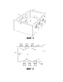
На Фиг. 1 представлен схематический вид в перспективе стекловаренной печи, с помощью которой настоящее изобретение может быть реализовано на практике.FIG. 1 is a schematic perspective view of a glass furnace with which the present invention can be put into practice.
На Фиг. 2 представлен вид сверху печи, изображенной на Фиг. 1.FIG. 2 is a top view of the furnace shown in FIG. one.
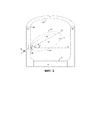
На Фиг. 3 представлен вид печи, изображенной на Фиг. 1, в поперечном сечении, выполненном вдоль вертикальной плоскости, проходящей через горелку 11.FIG. 3 is a view of the furnace shown in FIG. 1, in cross-section, along the vertical plane passing through the
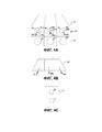
На Фиг. 4А представлен вид в перспективе горелки, подходящей для использования в настоящем изобретении.FIG. 4A is a perspective view of a burner suitable for use in the present invention.
На Фиг. 4B представлен вид сверху горелки, показанной на Фиг. 4A.FIG. 4B is a top view of the burner shown in FIG. 4A.
На Фиг. 4С представлен вид спереди в горизонтальной проекции другой горелки, подходящей для использования в настоящем изобретении.FIG. 4C is a front elevational view of another burner suitable for use in the present invention.
Подробное описание изобретенияDetailed Description of the Invention
Как показано на Фиг. 1, 2 и 3, печь 1 представляет собой стекловаренную печь или любую другую печь, в которой загрузка подвергается воздействию очень высоких температур, обеспечиваемых за счет сгорания внутри печи. Примеры других печей, подходящих для использования с настоящим изобретением, включают печи для сжигания отходов, печи для плавки цветных металлов, таких как медь или алюминий, и печи для нагрева или повторного нагрева изделий из черных металлов, таких как прутки, стержни и слитки.As shown in FIG. 1, 2 and 3, the
В стекловаренной печи ингредиенты стекольной шихты, такие как кальцинированная сода, селитра, диоксид кремния, силикат натрия и/или битое стекло («стекольный бой»), подают в печь через загрузочное отверстие 31 (Фиг. 2), где они сплавляются с образованием ванны 6 расплавленного стекла. Печь 1 включает в себя боковые стенки 2A и 2B, торцевую стенку 3 и переднюю стенку 4, которая включает в себя отверстие 9, через которое расплавленное стекло, находящееся внутри печи 1, может вытекать из печи 1. Купол 5, показанный на Фиг. 3, примыкает к боковым стенкам 2A и 2B, торцевой стенке 3 и передней стенке 4. Верхом боковых стенок 2A и 2B считают место, где наклон внутренней части печи изменяется от наклона 21 (обычно вертикаль) боковых стенок к ориентации внутренней поверхности 23 купола, которая может быть изогнутой (как показано на Фиг. 3) или плоской, например горизонтальной или расположенной под углом относительно вертикали. Купол 5 не показан на Фиг. 1 и 2 для удобства рассмотрения внутренней части печи 1.In a glass melting furnace, glass batch ingredients, such as soda ash, nitrate, silicon dioxide, sodium silicate and / or broken glass (“glass blasts”), are fed into the furnace through the feed opening 31 (FIG. 2), where they fuse to form a
Печь 1 может быть оснащена одной горелкой 11, но предпочтительно в ней предусмотрено множество горелок 11 в боковых стенках 2A и 2B. На Фиг. 1 и 2 показан один из многих возможных вариантов осуществления такой конструкции, причем горелки в противоположных боковых стенках предусмотрены в шахматном порядке таким образом, что горелки не обращены непосредственно друг к другу.The
В каждую горелку 11 подают газообразный окислитель 15 и топливо 16. В настоящем документе дополнительно описаны подходящие окислители и топливо.
Как показано на Фиг. 3, горелка 11 (которая, как указано, может быть единственной такой имеющейся горелкой или предпочтительно представляет собой одну из многих других таких горелок 11 в одной или предпочтительно обеих боковых стенках печи) расположена в боковой стенке 2A таким образом, что расстояние от верхней поверхности 8 расплавленного стекла 6 до отверстия 39 в боковой стенке составляет от 35% до 65% от общего расстояния от верхней поверхности расплавленного стекла 8 до верха боковой стенки 2A, в которой расположено отверстие 39.As shown in FIG. 3, the burner 11 (which, as indicated, may be the only such burner available or is preferably one of many other
Горелка или горелки 11 в соответствии с настоящим изобретением установлены таким образом, что горелка создает пламя, которое проходит от горелки у отверстия 39 или через него в боковой стенке вверх к куполу 5 вдоль линии A-A, которая образует угол G до 15 градусов (предпочтительно больше нуля градусов) относительно горизонтальной плоскости H-H, которая проходит через горелку. Линия A-A представляет собой воображаемую линию, которая является эквидистантной (равноудаленной) от самых удаленных краев пламени и которая проходит в направлении от выхода горелки в печь. Например, когда горелка образует широкое плоское пламя, предполагается, что линия A-A представляет собой воображаемую линию, которая расположена в плоскости пламени и равноудалена от внешних краев пламени в плоскости; а когда горелка образует коническое пламя, предполагается, что линия A-A представляет собой воображаемую линию, которая является осью вращения этой конической формы. Предполагается, что линия A-A встречается с горелкой у отверстия горелки, из которого выходят и сгорают топливо и кислород.A burner or
Линия A-A, вдоль которой пламя проходит от горелки, предпочтительно расположена в вертикальной плоскости, которая перпендикулярна боковой стенке, от которой пламя проходит в печь. Таким образом, в печи, у которой четыре стенки образуют прямоугольник, пламя предпочтительно проходит «прямо через» внутреннюю часть печи к противоположной боковой стенке. Однако эта вертикальная плоскость может образовывать угол до 30 градусов относительно боковой стенки, от которой проходит пламя.Line A-A, along which the flame passes from the burner, is preferably located in a vertical plane that is perpendicular to the side wall from which the flame passes into the furnace. Thus, in a furnace in which the four walls form a rectangle, the flame preferably passes “straight through” the inside of the furnace to the opposite side wall. However, this vertical plane can form an angle of up to 30 degrees relative to the side wall from which the flame passes.
Во время работы каждая горелка 11 сжигает газообразный окислитель 15 и топливо 16 во внутренней части печи 1. Газообразный окислитель 15 подают в каждую горелку 11. Окислитель 15 представляет собой любой газ или газовую смесь с содержанием кислорода. Одним подходящим окислителем 15 является воздух с содержанием кислорода 20,9 об.%. Предпочтительно, чтобы содержание кислорода в газообразном окислителе 15 составляло по меньшей мере 21 об.%, более предпочтительно - более 50 об.%, еще более предпочтительно - более 85 об.%.During operation, each
Окислитель 15 с желаемым содержанием кислорода можно обеспечить любым из нескольких способов. Его можно получить из отдельного коммерческого источника уже с желаемым содержанием кислорода. Его можно получить путем объединения воздуха и потока с более высоким содержанием, содержание кислорода в котором превышает желаемое конечное содержание кислорода для окислителя 15; в этом случае поток с более высоким содержанием можно получить из отдельного коммерческого источника или можно получить посредством местной промышленной воздухоразделительной установки, которая обеспечивает поток продукта, содержание кислорода в котором превышает желаемое общее содержание кислорода в окислителе 15.The
Подходящие виды топлива 16 включают любой газообразный или жидкий углеводород, такой как нефтепродукт, или углеводород или смесь углеводородов, которые представляют собой жидкости в стандартных условиях (т. е. при температуре 25 °C и давлении 0,1 мегапаскаль (1 атм)). Предпочтительными видами топлива являются углеводороды, которые являются газообразными при стандартных условиях, такие как природный газ, метан, пропан и т. п.
Окислитель 15, или топливо 16, или оба из них могут подаваться в каждую горелку 11 из их источника по питающим линиям, которые выполнены отдельно для каждой горелки. В альтернативном варианте осуществления окислитель 15, или топливо 16, или оба могут подаваться во множество горелок 11 через коллектор, подача в который осуществляется от его источника посредством одной питающей линии.
Окислитель и топливо подают в горелку или горелки 11 и сжигают. Скорости и стехиометрическое соотношение обеспечиваются в соответствии с представленным в настоящем документе описанием таким образом, чтобы получить преимущества настоящего изобретения.The oxidizer and fuel are fed to the burner or
Окислитель и топливо следует подавать в каждую горелку 11 с такими скоростями, чтобы при сгорании окислителя и топлива в горелке видимое пламя, образующееся в результате сгорания, никак не контактировало с боковой стенкой печи 1, расположенной напротив боковой стенки, в которой расположена горелка. Это помогает защитить противоположную боковую стенку от чрезмерного разрушения.The oxidizer and fuel should be supplied to each
Кроме того, окислитель и топливо следует подавать в горелку 11 с такими скоростями, чтобы видимое пламя, образующееся при сгорании окислителя и топлива, никак не контактировало с поверхностью 8 расплавленного стекла 6. Видимое пламя представлено на Фиг. 3 как пламя 41.In addition, the oxidizer and fuel should be fed into the
Кроме того, скорости, с которыми окислитель и топливо подаются в горелку 11, должны быть такими, чтобы видимое пламя, образующееся при сгорании окислителя и топлива, никак не контактировало с внутренней поверхностью купола 5.In addition, the speeds with which the oxidizer and the fuel are fed to the
Эти условия выполняются путем надлежащего обеспечения соответствующих скоростей подачи окислителя и топлива. Типичными примерами подходящих скоростей в центральных трубах подачи газа к горелкам являются скорость подачи окислителя в диапазоне 21-107 (м/с) (70-350 (футов/с)) и скорость подачи топлива 21-61 (м/с) (70-200 (футов/с)).These conditions are met by proper provision of appropriate oxidant and fuel feed rates. Typical examples of suitable speeds in the central gas supply pipes to the burners are the oxidant feed rate in the range of 21-107 (m / s) (70-350 (ft / s)) and the fuel feed rate of 21-61 (m / s) (70- 200 (ft / s)).
Пламя, которое формируется на горелке 11 в соответствии с настоящим изобретением, отличается тем, что радиационный тепловой поток от верхней поверхности пламени (обозначена как элемент 81 на Фиг. 3) к куполу 5 на любом заданном расстоянии от верхней поверхности пламени меньше радиационного теплового потока от нижней поверхности пламени (обозначена как элемент 82 на Фиг. 3) к расплавленному стеклу 6 на таком же заданном расстоянии от нижней поверхности пламени.The flame that forms on the
Это условие может выполняться путем осуществления сгорания при условиях, которые способствуют образованию слоя 83 на верхней поверхности пламени или вблизи нее, в котором общее количество несгоревшего топлива, частично сгоревшего топлива и продуктов, образовавшихся в результате частичного сгорания топлива, превышает их количество в областях пламени ниже этого слоя. Такое несгоревшее топливо, частично сгоревшее топливо и продукты, образовавшиеся в результате частичного сгорания, также можно называть «сажей». Это условие может выполняться путем осуществления «поэтапного сгорания», т.е. сгорания, при котором топливо подается в печь вблизи от места, где в печь подается только часть общего количества кислорода, необходимого для полного сгорания топлива, а оставшееся количество кислорода, необходимое для полного сгорания топлива, подается в печь на большем расстоянии от места подачи топлива.This condition can be fulfilled by burning under conditions that promote the formation of a
Образование желаемого слоя 83 можно стимулировать путем осуществления сгорания с помощью горелок, в которые топливо и окислитель подаются на разных высотах над расплавленным стеклом 6, причем топливо (и предпочтительно только часть окислителя, необходимого для полного сгорания этого топлива) подается выше того уровня, на который подают окислитель в количестве, требуемом в соответствии со стехиометрическим балансом. Примеры горелок, подходящих для такой эксплуатации, показаны на Фиг. 4A, 4B и 4C. Горелка, представленная на Фиг. 4A и 4B, относится к типу, описанному в патенте США № 6,132,204, и часто называется широкопламенной горелкой, поскольку пламя, которое обычно формируется при ее работе, является широким и относительно плоским.The formation of the desired
На Фиг. 4A горелка 11 принимает форму горелки 61, которая включает в себя верхний ряд 62 отверстий 64, 66 и 68 и нижний ряд 63 отверстий 65, 67 и 69. Отверстие 64 находится в конце канала, по которому подается один компонент из окислителя или топлива, предпочтительно окислитель. Отверстие 64b находится в конце канала, по которому подается другой компонент из окислителя или топлива, предпочтительно топливо. Отверстие 64b находится внутри отверстия 64 и предпочтительно расположено вFIG. 4A, the
отверстии 64 концентрически, образуя кольцевое пространство 64c.
Аналогично отверстие 66 находится в конце канала, по которому подается один компонент из окислителя или топлива, предпочтительно окислитель. Отверстие 66b находится в конце канала, по которому подается другой компонент из окислителя или топлива, предпочтительно топливо. Отверстие 66b находится внутри отверстия 66 и предпочтительно расположено в отверстии 66 концентрически, образуя кольцевое пространство 66c. Отверстие 68 находится в конце канала, по которому подается один компонент из окислителя или топлива, предпочтительно окислитель. Отверстие 68b находится в конце канала, по которому подается другой компонент из окислителя или топлива, предпочтительно топливо. Отверстие 68b находится внутри отверстия 68 и предпочтительно расположено в отверстии 68 концентрически, образуя кольцевое пространство 68c.Similarly, the
Предпочтительно, чтобы, как лучше всего показано на Фиг. 4B, отверстия 64 и 68 были ориентированы таким образом, чтобы каждая их соответствующая ось 64a и 68a имела форму расходящихся лучей относительно оси 66a отверстия 66. Отверстия 65 и 69 аналогично ориентированы таким образом, чтобы их соответствующие оси (не видны на виде сверху на Фиг. 4B) имели форму расходящихся лучей относительно оси отверстия 67.Preferably, as best shown in FIG. 4B, the
При предпочтительном способе работы горелки в соответствии с настоящим изобретением, представленной на Фиг. 4A и 4B, топливо подается в отверстия 64b, 66b и 68b и через них в печь 1, а окислитель подается в кольцевые пространства 64c, 66c и 68c и через них в печь 1. Окислитель подается в отверстия 65, 67 и 69 и через них в печь 1, в которой происходит сгорание топлива и окислителя.With the preferred method of operation of the burner in accordance with the present invention shown in FIG. 4A and 4B, the fuel is fed into the
Желаемый слой 83 в соответствии с настоящим изобретением предпочтительно обеспечивается путем подачи топлива через отверстия 64b, 66b и 68b и подачи окислителя через отверстия 64, 66 и 68 так, чтобы количества подаваемого кислорода позволяли топливу находиться в молярном избытке относительно кислорода. Предпочтительно, чтобы общее количество кислорода, подаваемого через отверстия 64, 66 и 68, составляло менее 30% от общего количества кислорода, необходимого для полного сгорания подаваемого топлива. Дополнительное количество кислорода, необходимое для полного сгорания топлива, содержится в окислителе, который подается через отверстия 65, 67 и 69. Не сгоревший в слое 83 материал сгорает в печи с этим дополнительным кислородом.The desired
На Фиг. 4С горелка 11 принимает форму горелки 71, которая включает в себя верхнее отверстие 72 и нижнее отверстие 73. При предпочтительном способе работы горелки в соответствии с настоящим изобретением, представленной на Фиг. 4С, топливо подается в отверстие 72 и через него в печь 1, а окислитель подается в отверстия 72 и 73 и через них в печь 1, где происходит сгорание топлива и окислителя. Топливо, подаваемое через отверстие 72, находится в стехиометрическом избытке относительно кислорода, содержащегося в окислителе, который подается через отверстие 72, а кислород в количестве, требуемом в соответствии со стехиометрическим балансом, подается через другие отверстия в печи.FIG. 4C, the
Осуществление сгорания таким образом приводит к образованию слоя 83, который частично экранирует купол от радиационной передачи тепла от пламени 81, тогда как нижние участки пламени (т. е. расположенные дальше от купола 5) обеспечивают желаемую беспрепятственную радиационную передачу тепла к расплавленному стеклу 6. Это и направленное под углом вверх пламя, которое приводит к снижению скорости атмосферы печи у поверхности расплавленного стекла, в свою очередь обеспечивает защиту купола от повреждения в результате воздействия чрезмерной температуры и защиту купола от попадания частиц из атмосферы печи (например, выделяющихся из расплавленного стекла), которые могут вступать в реакцию с внутренней поверхностью купола и ускорять нежелательное разрушение этой поверхности.Carrying out combustion in this way results in the formation of a
Способ работы в соответствии с настоящим изобретением также обеспечивает преимущества, которые заключаются в уменьшении образования оксидов азота и загрязняющих частиц в газообразных продуктах сгорания.The method of operation in accordance with the present invention also provides advantages, which consist in reducing the formation of nitrogen oxides and pollutants in gaseous combustion products.
Claims (8)
Applications Claiming Priority (3)
| Application Number | Priority Date | Filing Date | Title |
|---|---|---|---|
| US201462095999P | 2014-12-23 | 2014-12-23 | |
| US62/095,999 | 2014-12-23 | ||
| PCT/US2015/065997 WO2016106035A1 (en) | 2014-12-23 | 2015-12-16 | Upwardly angled burners in glass furnaces |
Publications (3)
| Publication Number | Publication Date |
|---|---|
| RU2017126114A RU2017126114A (en) | 2019-01-21 |
| RU2017126114A3 RU2017126114A3 (en) | 2019-01-21 |
| RU2684792C2 true RU2684792C2 (en) | 2019-04-15 |
Family
ID=55071217
Family Applications (1)
| Application Number | Title | Priority Date | Filing Date |
|---|---|---|---|
| RU2017126114A RU2684792C2 (en) | 2014-12-23 | 2015-12-16 | Burners for glass-melting furnaces oriented at angle upwards |
Country Status (12)
| Country | Link |
|---|---|
| US (1) | US10273178B2 (en) |
| EP (1) | EP3237342B1 (en) |
| JP (1) | JP2018500266A (en) |
| KR (1) | KR101960210B1 (en) |
| CN (1) | CN107231800B (en) |
| BR (1) | BR112017013672A2 (en) |
| CA (1) | CA2971701C (en) |
| ES (1) | ES2707738T3 (en) |
| MX (1) | MX2017008389A (en) |
| PT (1) | PT3237342T (en) |
| RU (1) | RU2684792C2 (en) |
| WO (1) | WO2016106035A1 (en) |
Cited By (1)
| Publication number | Priority date | Publication date | Assignee | Title |
|---|---|---|---|---|
| RU2762608C1 (en) * | 2021-05-18 | 2021-12-21 | федеральное государственное бюджетное образовательное учреждение высшего образования "Национальный исследовательский университет "МЭИ" (ФГБОУ ВО "НИУ "МЭИ") | Submersible combustion of fuel and oxidizer in bubble-type melting furnaces |
Families Citing this family (1)
| Publication number | Priority date | Publication date | Assignee | Title |
|---|---|---|---|---|
| CN106277718B (en) * | 2016-08-19 | 2019-03-15 | 巨石集团有限公司 | A kind of glass fibre tank furnace glass metal channel heating means |
Citations (6)
| Publication number | Priority date | Publication date | Assignee | Title |
|---|---|---|---|---|
| SU986873A1 (en) * | 1981-01-04 | 1983-01-07 | Всесоюзный Научно-Исследовательский Институт Теплоизоляционных И Акустических Строительных Материалов И Изделий | Tank furnace |
| SU1017691A1 (en) * | 1981-11-09 | 1983-05-15 | Научно-Производственное Объединение "Техэнергохимпром" | Method for melting mineral raw material |
| SU1306913A1 (en) * | 1985-11-05 | 1987-04-30 | Институт газа АН УССР | Directly fired bath furnace |
| WO2009092950A3 (en) * | 2008-01-10 | 2009-10-22 | L'air Liquide Societe Anonyme Pour L'etude Et L'exploitation Des Procedes Georges Claude | Glass furnace and glass making method |
| EA201001538A1 (en) * | 2008-03-25 | 2011-04-29 | Агк Гласс Юроп | GLASS FURNACE |
| RU2423324C2 (en) * | 2005-07-13 | 2011-07-10 | Сэн-Гобэн Изовер | Method of producing glass |
Family Cites Families (24)
| Publication number | Priority date | Publication date | Assignee | Title |
|---|---|---|---|---|
| US1894249A (en) * | 1929-12-11 | 1933-01-10 | Owens Illinois Glass Co | Heating apparatus for glass furnaces |
| US3837832A (en) | 1971-04-29 | 1974-09-24 | Ppg Industries Inc | Apparatus for making float glass |
| JPS5549130A (en) * | 1978-10-03 | 1980-04-09 | Nippon Sheet Glass Co Ltd | Removing method for nitrogen oxide in exhaust gas |
| FR2722272B1 (en) * | 1994-07-08 | 1996-08-23 | Air Liquide | COMBUSTION ASSEMBLY FOR AN OVEN AND METHOD FOR OPERATING THE SAME |
| US5628809A (en) | 1995-06-13 | 1997-05-13 | Praxair Technology, Inc. | Glassmelting method with reduced volatilization of alkali species |
| US5609481A (en) | 1995-06-13 | 1997-03-11 | Praxair Technology, Inc. | Direct-fired stratified atmosphere furnace system |
| US6253578B1 (en) * | 1996-04-12 | 2001-07-03 | Praxair Technology, Inc. | Glass melting process and apparatus with reduced emissions and refractory corrosion |
| JP3877440B2 (en) * | 1997-10-31 | 2007-02-07 | 大阪瓦斯株式会社 | Burner equipment for heating furnace |
| US5961689A (en) | 1998-03-03 | 1999-10-05 | Praxair Technology, Inc. | Method of protective atmosphere heating |
| US6132204A (en) | 1998-06-30 | 2000-10-17 | Praxair Technology, Inc. | Wide flame burner |
| US7833009B2 (en) * | 2004-09-10 | 2010-11-16 | Air Products And Chemicals, Inc. | Oxidant injection method |
| FR2879284B1 (en) | 2004-12-09 | 2007-01-19 | Air Liquide | METHOD OF MELTING A COMPOSITION OF RAW MATERIALS BY A BURNER IN VOUTE |
| WO2008063940A1 (en) * | 2006-11-17 | 2008-05-29 | Praxair Technology, Inc. | Reducing crown corrosion in a glassmelting furnace |
| US8904824B2 (en) * | 2008-03-25 | 2014-12-09 | Agc Glass Europe | Glass melting furnace |
| US20100104990A1 (en) | 2008-10-23 | 2010-04-29 | Sarmiento-Darkin Wladimir Y | Wide flame burner |
| CN201448850U (en) * | 2009-08-13 | 2010-05-05 | 泰山玻璃纤维有限公司 | Pure oxygen burner |
| JP5421728B2 (en) * | 2009-10-23 | 2014-02-19 | 大阪瓦斯株式会社 | Combustion apparatus and melting furnace for melting furnace |
| JP5737070B2 (en) * | 2010-09-02 | 2015-06-17 | 信越化学工業株式会社 | Titania-doped quartz glass and method for producing the same |
| JP5654857B2 (en) * | 2010-12-08 | 2015-01-14 | 大阪瓦斯株式会社 | Glass manufacturing method and glass manufacturing apparatus |
| US20130180290A1 (en) * | 2011-12-21 | 2013-07-18 | Hisashi Kobayashi | Controlling glassmelting furnace gas circulation |
| JP5892809B2 (en) * | 2012-02-20 | 2016-03-23 | 大阪瓦斯株式会社 | Combustion equipment for heating furnace |
| JP5959224B2 (en) * | 2012-02-20 | 2016-08-02 | 大阪瓦斯株式会社 | Combustion equipment for glass melting furnace |
| US20140170573A1 (en) * | 2012-12-19 | 2014-06-19 | Neil G. SIMPSON | BURNER UTILIZING OXYGEN LANCE FOR FLAME CONTROL AND NOx REDUCTION |
| CN203964672U (en) * | 2014-07-24 | 2014-11-26 | 苏州罗卡节能科技有限公司 | Energy-saving heating furnace |
-
2015
- 2015-12-16 ES ES15820766T patent/ES2707738T3/en active Active
- 2015-12-16 BR BR112017013672A patent/BR112017013672A2/en not_active Application Discontinuation
- 2015-12-16 RU RU2017126114A patent/RU2684792C2/en not_active IP Right Cessation
- 2015-12-16 EP EP15820766.2A patent/EP3237342B1/en not_active Not-in-force
- 2015-12-16 CA CA2971701A patent/CA2971701C/en not_active Expired - Fee Related
- 2015-12-16 PT PT15820766T patent/PT3237342T/en unknown
- 2015-12-16 WO PCT/US2015/065997 patent/WO2016106035A1/en not_active Ceased
- 2015-12-16 JP JP2017533795A patent/JP2018500266A/en active Pending
- 2015-12-16 KR KR1020177020174A patent/KR101960210B1/en not_active Expired - Fee Related
- 2015-12-16 CN CN201580074674.9A patent/CN107231800B/en not_active Expired - Fee Related
- 2015-12-16 US US14/970,907 patent/US10273178B2/en not_active Expired - Fee Related
- 2015-12-16 MX MX2017008389A patent/MX2017008389A/en unknown
Patent Citations (6)
| Publication number | Priority date | Publication date | Assignee | Title |
|---|---|---|---|---|
| SU986873A1 (en) * | 1981-01-04 | 1983-01-07 | Всесоюзный Научно-Исследовательский Институт Теплоизоляционных И Акустических Строительных Материалов И Изделий | Tank furnace |
| SU1017691A1 (en) * | 1981-11-09 | 1983-05-15 | Научно-Производственное Объединение "Техэнергохимпром" | Method for melting mineral raw material |
| SU1306913A1 (en) * | 1985-11-05 | 1987-04-30 | Институт газа АН УССР | Directly fired bath furnace |
| RU2423324C2 (en) * | 2005-07-13 | 2011-07-10 | Сэн-Гобэн Изовер | Method of producing glass |
| WO2009092950A3 (en) * | 2008-01-10 | 2009-10-22 | L'air Liquide Societe Anonyme Pour L'etude Et L'exploitation Des Procedes Georges Claude | Glass furnace and glass making method |
| EA201001538A1 (en) * | 2008-03-25 | 2011-04-29 | Агк Гласс Юроп | GLASS FURNACE |
Cited By (1)
| Publication number | Priority date | Publication date | Assignee | Title |
|---|---|---|---|---|
| RU2762608C1 (en) * | 2021-05-18 | 2021-12-21 | федеральное государственное бюджетное образовательное учреждение высшего образования "Национальный исследовательский университет "МЭИ" (ФГБОУ ВО "НИУ "МЭИ") | Submersible combustion of fuel and oxidizer in bubble-type melting furnaces |
Also Published As
| Publication number | Publication date |
|---|---|
| ES2707738T3 (en) | 2019-04-04 |
| WO2016106035A1 (en) | 2016-06-30 |
| KR101960210B1 (en) | 2019-03-19 |
| KR20170105525A (en) | 2017-09-19 |
| CN107231800A (en) | 2017-10-03 |
| US20160176744A1 (en) | 2016-06-23 |
| MX2017008389A (en) | 2017-11-28 |
| PT3237342T (en) | 2019-02-26 |
| CN107231800B (en) | 2020-02-07 |
| EP3237342A1 (en) | 2017-11-01 |
| CA2971701A1 (en) | 2016-06-30 |
| EP3237342B1 (en) | 2018-11-21 |
| CA2971701C (en) | 2019-04-30 |
| JP2018500266A (en) | 2018-01-11 |
| RU2017126114A (en) | 2019-01-21 |
| BR112017013672A2 (en) | 2018-03-13 |
| US10273178B2 (en) | 2019-04-30 |
| RU2017126114A3 (en) | 2019-01-21 |
Similar Documents
| Publication | Publication Date | Title |
|---|---|---|
| JP6705849B2 (en) | Two-stage oxygen fuel burner | |
| AU748058B2 (en) | Roof-mounted oxygen-fuel burner for a glass melting furnace and process of using the oxygen-fuel burner | |
| US5934899A (en) | In-line method of burner firing and NOx emission control for glass melting | |
| ES2253186T3 (en) | METHOD FOR INCREASING HEATING IN A GLASS FUSION OVEN USING A FUEL AND OXYGEN BURNER MOUNTED ON THE ROOF. | |
| CZ302602B6 (en) | Method of heating glass melting furnace using a multistage oxygen-fuel burner disposed in the furnace roof | |
| CA2123590C (en) | Oxygen/fuel firing of furnaces with massive, low velocity, turbulent flames | |
| TW457351B (en) | Fuel and air compartment arrangement NOx tangential firing system | |
| US12275663B2 (en) | Multi-chamber submerged combustion melter and system | |
| RU2684792C2 (en) | Burners for glass-melting furnaces oriented at angle upwards | |
| ZA200803764B (en) | Solid fuel combustion for industrial melting with a slagging combustor | |
| US20150128647A1 (en) | Glass furnace forehearth heating | |
| CN206037015U (en) | Low NOx's oxy -fuel combustion device | |
| ES2929937T3 (en) | Reduced fouling in localized combustion | |
| KR20120029464A (en) | Method for processing oxidizable materials | |
| CN103269987A (en) | Burner for a glass melting furnace comprising cooling | |
| SU910782A1 (en) | Device for afterburning fume gases in martin furnaces | |
| RU2306482C1 (en) | Burning device | |
| BR112020006962B1 (en) | METHODS FOR COMBUSTING FUEL IN A FURNACE | |
| JPH03255808A (en) | incinerator |
Legal Events
| Date | Code | Title | Description |
|---|---|---|---|
| MM4A | The patent is invalid due to non-payment of fees |
Effective date: 20201217 |