RU2676154C2 - Pin for supporting parent reels in paper converting plants - Google Patents
Pin for supporting parent reels in paper converting plants Download PDFInfo
- Publication number
- RU2676154C2 RU2676154C2 RU2017113925A RU2017113925A RU2676154C2 RU 2676154 C2 RU2676154 C2 RU 2676154C2 RU 2017113925 A RU2017113925 A RU 2017113925A RU 2017113925 A RU2017113925 A RU 2017113925A RU 2676154 C2 RU2676154 C2 RU 2676154C2
- Authority
- RU
- Russia
- Prior art keywords
- shank
- latch
- latch according
- sectors
- specified
- Prior art date
Links
Images


Classifications
-
- B—PERFORMING OPERATIONS; TRANSPORTING
- B65—CONVEYING; PACKING; STORING; HANDLING THIN OR FILAMENTARY MATERIAL
- B65H—HANDLING THIN OR FILAMENTARY MATERIAL, e.g. SHEETS, WEBS, CABLES
- B65H19/00—Changing the web roll
- B65H19/10—Changing the web roll in unwinding mechanisms or in connection with unwinding operations
- B65H19/12—Lifting, transporting, or inserting the web roll; Removing empty core
- B65H19/126—Lifting, transporting, or inserting the web roll; Removing empty core with both-ends supporting arrangements
-
- B—PERFORMING OPERATIONS; TRANSPORTING
- B65—CONVEYING; PACKING; STORING; HANDLING THIN OR FILAMENTARY MATERIAL
- B65H—HANDLING THIN OR FILAMENTARY MATERIAL, e.g. SHEETS, WEBS, CABLES
- B65H19/00—Changing the web roll
- B65H19/10—Changing the web roll in unwinding mechanisms or in connection with unwinding operations
- B65H19/12—Lifting, transporting, or inserting the web roll; Removing empty core
-
- B—PERFORMING OPERATIONS; TRANSPORTING
- B65—CONVEYING; PACKING; STORING; HANDLING THIN OR FILAMENTARY MATERIAL
- B65H—HANDLING THIN OR FILAMENTARY MATERIAL, e.g. SHEETS, WEBS, CABLES
- B65H2301/00—Handling processes for sheets or webs
- B65H2301/40—Type of handling process
- B65H2301/41—Winding, unwinding
- B65H2301/413—Supporting web roll
- B65H2301/4134—Both ends type arrangement
- B65H2301/41346—Both ends type arrangement separate elements engaging each end of the roll (e.g. chuck)
-
- B—PERFORMING OPERATIONS; TRANSPORTING
- B65—CONVEYING; PACKING; STORING; HANDLING THIN OR FILAMENTARY MATERIAL
- B65H—HANDLING THIN OR FILAMENTARY MATERIAL, e.g. SHEETS, WEBS, CABLES
- B65H2301/00—Handling processes for sheets or webs
- B65H2301/40—Type of handling process
- B65H2301/41—Winding, unwinding
- B65H2301/417—Handling or changing web rolls
- B65H2301/4171—Handling web roll
- B65H2301/4173—Handling web roll by central portion, e.g. gripping central portion
- B65H2301/41732—Handling web roll by central portion, e.g. gripping central portion by crane
-
- B—PERFORMING OPERATIONS; TRANSPORTING
- B65—CONVEYING; PACKING; STORING; HANDLING THIN OR FILAMENTARY MATERIAL
- B65H—HANDLING THIN OR FILAMENTARY MATERIAL, e.g. SHEETS, WEBS, CABLES
- B65H2405/00—Parts for holding the handled material
- B65H2405/40—Holders, supports for rolls
- B65H2405/42—Supports for rolls fully removable from the handling machine
- B65H2405/422—Trolley, cart, i.e. support movable on floor
-
- B—PERFORMING OPERATIONS; TRANSPORTING
- B65—CONVEYING; PACKING; STORING; HANDLING THIN OR FILAMENTARY MATERIAL
- B65H—HANDLING THIN OR FILAMENTARY MATERIAL, e.g. SHEETS, WEBS, CABLES
- B65H2405/00—Parts for holding the handled material
- B65H2405/40—Holders, supports for rolls
- B65H2405/42—Supports for rolls fully removable from the handling machine
- B65H2405/423—Overhead means, gantry
-
- B—PERFORMING OPERATIONS; TRANSPORTING
- B65—CONVEYING; PACKING; STORING; HANDLING THIN OR FILAMENTARY MATERIAL
- B65H—HANDLING THIN OR FILAMENTARY MATERIAL, e.g. SHEETS, WEBS, CABLES
- B65H2511/00—Dimensions; Position; Numbers; Identification; Occurrences
- B65H2511/10—Size; Dimensions
- B65H2511/15—Height, e.g. of stack
-
- B—PERFORMING OPERATIONS; TRANSPORTING
- B65—CONVEYING; PACKING; STORING; HANDLING THIN OR FILAMENTARY MATERIAL
- B65H—HANDLING THIN OR FILAMENTARY MATERIAL, e.g. SHEETS, WEBS, CABLES
- B65H2515/00—Physical entities not provided for in groups B65H2511/00 or B65H2513/00
- B65H2515/30—Forces; Stresses
- B65H2515/31—Tensile forces
-
- B—PERFORMING OPERATIONS; TRANSPORTING
- B65—CONVEYING; PACKING; STORING; HANDLING THIN OR FILAMENTARY MATERIAL
- B65H—HANDLING THIN OR FILAMENTARY MATERIAL, e.g. SHEETS, WEBS, CABLES
- B65H2553/00—Sensing or detecting means
- B65H2553/20—Sensing or detecting means using electric elements
- B65H2553/21—Variable resistances, e.g. rheostats, potentiometers or strain gauges
-
- B—PERFORMING OPERATIONS; TRANSPORTING
- B65—CONVEYING; PACKING; STORING; HANDLING THIN OR FILAMENTARY MATERIAL
- B65H—HANDLING THIN OR FILAMENTARY MATERIAL, e.g. SHEETS, WEBS, CABLES
- B65H2801/00—Application field
- B65H2801/84—Paper-making machines
Abstract
Description
Настоящее изобретение относится к фиксатору, предназначенному для обеспечения опоры для материнских рулонов в установках для конвертинга бумаги.The present invention relates to a latch designed to provide support for mother rolls in paper converting plants.
Известно, что производство бумажных логов предполагает подачу непрерывного бумажного полотна вдоль заданной траектории. Бумажное полотно перфорируют в поперечном направлении в заданном месте указанной траектории так, чтобы оно было разделено на листы заданной длины, разделяемые путем отрыва. Кроме того, используют трубчатые элементы (обычно называемые сердечниками/втулками/гильзами), на поверхности которых наносят заданное количество клея для обеспечения возможности приклеивания первого листа лога, подлежащего формированию. Кроме того, используют намоточные валики, которые расположены и функционируют на станции формирования логов и которые вызывают вращение сердечника, на который наматывается бумага. Формирование лога заканчивается, когда заданное количество бумаги будет намотано на сердечник. После этого формируют другой лог. Когда формирование лога будет завершено, последний лист лога должен быть приклеен к расположенному под ним листу для избежания самопроизвольного разматывания лога. После этого каждый лог разделяют на множество более коротких рулонов посредством отрезных машин.It is known that the production of paper logs involves the supply of a continuous paper web along a given path. The paper web is perforated in the transverse direction at a given location of the specified path so that it is divided into sheets of a given length, separated by tearing. In addition, tubular elements (usually called cores / bushings / sleeves) are used, on the surface of which a predetermined amount of glue is applied to enable the first sheet of log to be glued to be glued. In addition, winding rollers are used that are located and operate at the logging station and which cause rotation of the core on which the paper is wound. Logging ends when a predetermined amount of paper is wound around the core. After that, another log is formed. When the formation of the log is completed, the last sheet of the log should be glued to the sheet located under it to avoid spontaneous unwinding of the log. After that, each log is divided into many shorter rolls by means of cutting machines.
Для обеспечения возможности надлежащего выполнения процесса установка для конвертинга бумаги всегда содержит раскат, на котором размещают материнские рулоны, с которых подают бумажное полотно. Раскаты содержат, в частности, основание для обеспечения опоры для каждого материнского рулона, и последний может вращаться вокруг его продольной оси, поскольку он присоединен к двум опорным фиксаторам, каждый из которых вставлен с возможностью удаления на соответствующей стороне материнского рулона. При размотке бумаги материнский рулон находится на основании раската, и фиксаторы находятся внутри материнского рулона, при этом, как правило, когда материнский рулон будет почти израсходован и должен быть заменен, фиксаторы извлекают для его освобождения.To ensure that the process can be performed properly, the paper converting plant always contains a peal on which the mother rolls from which the paper web is fed are placed. The peals contain, in particular, a base for providing support for each mother roll, and the latter can rotate around its longitudinal axis, since it is attached to two support clips, each of which is inserted with the possibility of removal on the corresponding side of the mother roll. When unwinding paper, the mother roll is located on the base of the roll, and the latches are inside the mother roll, and, as a rule, when the mother roll is almost used up and needs to be replaced, the latches are removed to release it.
Настоящее изобретение относится к конструкции фиксаторов, предназначенным для обеспечения опоры для материнских рулонов в раскатах и направлено на облегчение загрузки материнских рулонов на раскаты и, соответственно, манипулирования ими и их удаления.The present invention relates to the design of latches designed to provide support for mother rolls in peals and is aimed at facilitating loading of mother rolls on peals and, accordingly, manipulating and removing them.
Данный результат достигается в соответствии с настоящим изобретением посредством разработки устройства, имеющего признаки, указанные в пункте 1 формулы изобретения. Другие признаки настоящего изобретения являются предметом зависимых пунктов формулы изобретения.This result is achieved in accordance with the present invention by developing a device having the features specified in
Фиксатору в соответствии с настоящим изобретением придана такая форма, что он удерживается присоединенным к соответствующему рычагу мостового крана, используемого для перемещения материнского рулона, и при этом он по-прежнему опирается на соответствующую опору раската. Кроме того, фиксатор в соответствии с настоящим изобретением является простым в изготовлении и очень дешевым по отношению к обеспечиваемым преимуществам.The latch in accordance with the present invention is shaped so that it is held attached to the corresponding lever of the overhead crane used to move the mother roll, while still resting on the corresponding pedestal support. In addition, the latch in accordance with the present invention is easy to manufacture and very cheap in relation to the benefits provided.
Эти и другие преимущества и признаки данного изобретения будут наилучшим образом поняты любым специалистом в данной области техники благодаря нижеприведенному описанию и приложенным чертежам, которые представлены в качестве примера, но не должны рассматриваться в ограничивающем смысле, в которых:These and other advantages and features of this invention will be best understood by any person skilled in the art due to the description below and the attached drawings, which are presented as an example, but should not be construed in a limiting sense, in which:
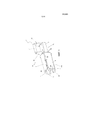
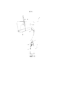
- фиг.1 представляет собой схематический вид в перспективе фиксатора в соответствии с настоящим изобретением;- figure 1 is a schematic perspective view of a latch in accordance with the present invention;
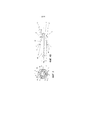
- фиг.2 показывает разжимной фиксатор по фиг.1 с двумя секторами, удаленным, чтобы лучше показать внутреннюю часть;- figure 2 shows the expandable latch of figure 1 with two sectors removed to better show the inside;
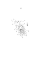
- фиг.3 представляет собой поперечное сечение фиксатора, показанного на фиг.1;- figure 3 is a cross section of the latch shown in figure 1;
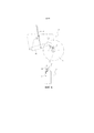
- фиг.4А представляет собой разрез, выполненный по линии А-А на фиг.3;- figa is a section taken along the line aa in figure 3;
- фиг.4В показывает группу компонентов, отделенных от узла, показанного на фиг.4А;- figv shows a group of components separated from the node shown in figa;
- фиг.5 представляет собой вид, аналогичный фиг.4А, но показывает фиксатор в сжатой конфигурации вместо расширенной конфигурации;- figure 5 is a view similar to figa, but shows the latch in a compressed configuration instead of an expanded configuration;
- фиг.6-11 схематически показывают последовательность этапов, относящихся к манипулированию фиксатором посредством мостового крана, при этом материнский рулон показан только на фиг.6 для более наглядной иллюстрации перемещений;- Fig.6-11 schematically show the sequence of steps related to manipulating the latch by means of an overhead crane, while the mother roll is shown only in Fig.6 to more clearly illustrate the movements;
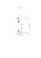
- фиг.12 представляет собой схематический вид сбоку материнского рулона с фиксаторами, вставленными в противоположные концы соответствующего сердечника;- Fig. 12 is a schematic side view of a mother roll with latches inserted at opposite ends of a corresponding core;
- фиг.13 и 14 представляют собой два фрагмента фиг.12;- Fig.13 and 14 are two fragments of Fig.12;
- фиг.15 схематически показывает силы, действующие на материнский рулон (А) при подъеме последнего;- Fig.15 schematically shows the forces acting on the mother roll (A) when lifting the latter;
Фиксатор (Р) в соответствии с настоящим изобретением представляет собой фиксатор такого типа, который предназначен для вставки в соответствующий конец сердечника (10) материнского рулона (1), который может быть использован в раскате установки для конвертинга бумаги.The latch (P) in accordance with the present invention is a latch of the type that is designed to be inserted into the corresponding end of the mother core (10) roll (1), which can be used in the roll of the installation for converting paper.
Фиксатор (Р) имеет наружную сторону (РХ) и внутреннюю сторону (PN), при этом внутренняя сторона (PN) предназначена для вставки в сердечник (10) рулона (1) и наружная сторона является внешней по отношению к тому же самому рулону (1), когда внутренняя сторона (PN) находится внутри сердечника (10). На фиг.1 и фиг.2 наружная сторона (РХ) находится справа, в то время как внутренняя сторона (РN) находится слева. Фиксатор (Р) является по существу симметричным относительно центральной продольной оси (x-x).The latch (P) has an outer side (PX) and an inner side (PN), while the inner side (PN) is designed to be inserted into the core (10) of the roll (1) and the outside is external to the same roll (1 ) when the inside (PN) is inside the core (10). In figure 1 and figure 2, the outer side (PX) is on the right, while the inner side (PN) is on the left. The latch (P) is substantially symmetrical about the central longitudinal axis (x-x).
Наружная сторона (РХ) фиксатора (Р) образована хвостовиком (2), продольная ось которого совпадает с продольной осью (x-x) фиксатора (Р). На указанном хвостовике (2) закреплена ручка (3), образованная двумя параллельными консольными элементами (30), выступающими в радиальном направлении от хвостовика (2) и соединенными элементом (31), параллельным указанной продольной оси (x-x). Ручка (3) применяется с верхней стороны хвостовика (2), то есть со стороны последнего, которая при эксплуатации повернута вверх. Хвостовик (2) является полым.The outer side (PX) of the retainer (P) is formed by a shank (2), the longitudinal axis of which coincides with the longitudinal axis (x-x) of the retainer (P). A handle (3) is formed on said shank (2), formed by two parallel cantilever elements (30) protruding radially from the shank (2) and connected by an element (31) parallel to the specified longitudinal axis (x-x). The handle (3) is used on the upper side of the shank (2), that is, on the side of the shank, which is turned up during operation. The shank (2) is hollow.
В соответствии с примером, показанным на чертежах, внутренняя сторона (PN) фиксатора (Р) является расширяющейся: указанная внутренняя сторона расширяется (как показано на фиг.1, фиг.2, фиг.3, фиг.4А и фиг.4В), когда она вставлена в сердечник (10) рулона (1), для входа в контактное взаимодействие с последним, при этом она сжимается (как показано на фиг.5) для ее вставки в сердечник (10) или вывода из контактного взаимодействия с рулоном.According to the example shown in the drawings, the inner side (PN) of the retainer (P) is expandable: said inner side expands (as shown in FIG. 1, FIG. 2, FIG. 3, FIG. 4A and FIG. 4B), when it is inserted into the core (10) of the roll (1) to enter into contact interaction with the latter, it is compressed (as shown in FIG. 5) to insert it into the core (10) or to withdraw from the contact interaction with the roll.
Наружная поверхность внутренней стороны (PN) образована множеством секторов (4), число которых в данном примере составляет четыре, и каждый из которых образован участком с цилиндрической поверхностью со свободным передним концом (40) и задним концом (41). Фиксатор (Р) также содержит элемент (5), имеющий: заднюю часть (50), вставленную в продольном направлении в полый хвостовик (2) при размещении подшипников (51) между ними; переднюю часть (52), обращенную к переднему концу (40) секторов (4) и состоящую из продольной выступающей части задней части (50), и наружную чашеобразную часть (53), внутренний диаметр (d53) которой превышает наружный диаметр хвостовика (2), в промежуточном месте между задней частью (50) и передней частью (52). На практике задняя часть (50) элемента (5) вставлена в хвостовик (2), промежуточная часть (53) является внешней по отношению к хвостовику, который частично (то есть в его наиболее выдвинутой вперед части) находится внутри чашеобразной промежуточной части (53), и передняя часть (52) образует продолжение элемента (5), которое, как показано на чертежах, является внутренним по отношению к секторам (4).The outer surface of the inner side (PN) is formed by a plurality of sectors (4), the number of which in this example is four, and each of which is formed by a section with a cylindrical surface with a free front end (40) and a rear end (41). The latch (P) also contains an element (5) having: a rear part (50) inserted longitudinally into the hollow shank (2) when placing bearings (51) between them; the front part (52) facing the front end (40) of the sectors (4) and consisting of a longitudinal protruding part of the rear part (50), and the outer cup-shaped part (53), whose inner diameter (d53) exceeds the outer diameter of the shank (2) , in the intermediate place between the rear (50) and the front (52). In practice, the back part (50) of the element (5) is inserted into the shank (2), the intermediate part (53) is external to the shank, which is partially (i.e. in its most advanced part) located inside the cup-shaped intermediate part (53) , and the front part (52) forms a continuation of the element (5), which, as shown in the drawings, is internal to the sectors (4).
Задний конец (41) каждого сектора (4) удерживается относительно чашеобразной части (53) элемента (5) посредством стержня (42), вставленного в радиальный выступ (54), выступающий наружу от той же самой чашеобразной части (53). Число указанных выступов (54) в данном примере составляет четыре, и они расположены на угловом расстоянии, составляющим 90°, друг от друга. Ось каждого стержня (42) ориентирована вдоль направления по касательной относительно хвостовика (2), поверхность которого является цилиндрической. Кроме того, каждый стержень (42) расположен на заданном расстоянии от наружной поверхности хвостовика (2), когда стержень (42) вставлен в выступ (54), который функционирует в качестве дистанционирующего элемента.The rear end (41) of each sector (4) is held relative to the cup-shaped part (53) of the element (5) by means of a rod (42) inserted into the radial protrusion (54) protruding outward from the same cup-shaped part (53). The number of these protrusions (54) in this example is four, and they are located at an angular distance of 90 ° from each other. The axis of each rod (42) is oriented along the direction tangential to the shaft (2), the surface of which is cylindrical. In addition, each rod (42) is located at a predetermined distance from the outer surface of the shank (2) when the rod (42) is inserted into the protrusion (54), which functions as a spacer element.
Каждый сектор (4) также удерживается относительно передней части (52) указанного элемента (5) посредством соединительной штанги (55), шарнирно присоединенной с одной стороны (нижней стороны) к втулке (56), установленной с возможностью скольжения в продольном направлении на передней части (52) элемента (5), и с противоположной стороны (верхней стороны) к внутренней поверхности соответствующего сектора (4). Соединение соединительной штанги (55) с втулкой (56) образовано стержнем (57), ось которого параллельна стержню (42), который соединяет заднюю часть (41) сектора (4) с соответствующим выступом (54) чашеобразной части (53); соединение той же самой соединительной штанги (55) с внутренней стороной сектора (4) выполнено посредством дополнительного стержня (58), параллельного предыдущему стержню (57).Each sector (4) is also held relative to the front part (52) of said element (5) by means of a connecting rod (55) pivotally attached on one side (lower side) to a sleeve (56) mounted for sliding in the longitudinal direction on the front part (52) of the element (5), and from the opposite side (upper side) to the inner surface of the corresponding sector (4). The connection of the connecting rod (55) with the sleeve (56) is formed by a rod (57), the axis of which is parallel to the rod (42), which connects the rear part (41) of the sector (4) with the corresponding protrusion (54) of the cup-shaped part (53); the connection of the same connecting rod (55) with the inside of the sector (4) is made by means of an additional rod (58) parallel to the previous rod (57).
Перед передним концом передней части (52) элемента (5) расположена пневматическая пружина (6), размещенная между двумя пластинами (60, 61), которые ортогональны указанной оси (x-x). Первая пластина (60) имеет заднюю выступающую часть (62), которая функционирует в качестве дистанционирующего элемента и прикреплена к переднему концу передней части (52) элемента (5). Вторая пластина (61) находится с противоположной стороны по отношению к пневматической пружине (6). Несколько штанг (63) соединяют вторую пластину (61) с указанной втулкой (56): каждая штанга (63) прикреплена с одной стороны ко второй пластине (61) и с противоположной стороны к заднему выступу (560) втулки (56) и проходит свободно через соответствующее отверстие, образованное в первой пластине (60). На каждой из штанг (63) установлена цилиндрическая винтовая пружина (64). Штанги (63) и цилиндрические винтовые пружины (64) ориентированы параллельно указанной оси (x-x), и число штанг (63) составляет четыре в примере, показанном на чертежах.In front of the front end of the front part (52) of the element (5), there is a pneumatic spring (6) located between two plates (60, 61) that are orthogonal to the specified axis (x-x). The first plate (60) has a rear protruding part (62), which functions as a spacer element and is attached to the front end of the front part (52) of the element (5). The second plate (61) is located on the opposite side with respect to the air spring (6). Several rods (63) connect the second plate (61) to the indicated sleeve (56): each rod (63) is attached on one side to the second plate (61) and on the opposite side to the rear protrusion (560) of the sleeve (56) and passes freely through the corresponding hole formed in the first plate (60). A coil spring (64) is mounted on each of the rods (63). The rods (63) and coil springs (64) are oriented parallel to the indicated axis (x-x), and the number of rods (63) is four in the example shown in the drawings.
Когда пневматическая пружина (6) «разгружена», то есть сжата, воздействие цилиндрических винтовых пружин (64) является таким, чтобы удерживать втулку (56) сдвинутой назад на части (52) элемента (5): в этом состоянии задняя часть втулки (56) поджимается пружинами (64) к опорной поверхности (59), имеющейся на элементе (5) между промежуточной частью (53) и передней частью (52), и секторы (4) открыты, при этом соединительные штанги (55) ориентированы вдоль радиального направления относительно оси (x-x), то есть ориентированы параллельно нагрузке, действующей на фиксатор (Р). Секторы (4) удерживаются нормально открытыми посредством пружин (64).When the pneumatic spring (6) is "unloaded", that is, compressed, the action of the coil springs (64) is such as to keep the sleeve (56) shifted back to the part (52) of the element (5): in this state, the back of the sleeve (56) ) is pressed by springs (64) to the supporting surface (59) on the element (5) between the intermediate part (53) and the front part (52), and the sectors (4) are open, while the connecting rods (55) are oriented along the radial direction relative to the axis (xx), i.e. oriented parallel to the load acting on the fixed Torr (P). Sectors (4) are held normally open by means of springs (64).
При «нагружении», то есть расширении, пневматической пружины (6) обеспечивается преодоление сопротивления пружин (64), и втулка (56) перемещается вперед вместе с основанием соединительных штанг (55), в результате чего секторы (4) закрываются при взаимном сближении соответствующих передних концов (40).When "loading", that is, expanding, the pneumatic spring (6) overcomes the resistance of the springs (64), and the sleeve (56) moves forward along with the base of the connecting rods (55), as a result of which the sectors (4) are closed when the corresponding front ends (40).
Сжатый воздух вводится в пневматическую пружину (6) или удаляется через продольное сквозное отверстие (5F), образованное в элементе (5).Compressed air is introduced into the pneumatic spring (6) or is removed through a longitudinal through hole (5F) formed in the element (5).
Таким образом, секторы (4) могут быть открыты и закрыты посредством их поворота вокруг стержней (42).Thus, sectors (4) can be opened and closed by turning them around the rods (42).
Передние концы (40) секторов (4) образуют по существу круглую конфигурацию, наружный диаметр (4а; 4с) которой изменяется в соответствии с конфигурацией (открытой/закрытой) тех же самых секторов (4) между максимальным значением (4а) и минимальным значением (4с). Разность (Δ) указанного максимального значения (4а) и указанного минимального значения (4с) предпочтительно составляет от 10% до 30% от максимального значения (4а): 0,30*(4а)≥Δ=(4а-4с)≥0,10*(4а).The front ends (40) of sectors (4) form an essentially circular configuration, the outer diameter (4a; 4c) of which changes in accordance with the configuration (open / closed) of the same sectors (4) between the maximum value (4a) and the minimum value ( 4c). The difference (Δ) of the indicated maximum value (4a) and the specified minimum value (4c) is preferably from 10% to 30% of the maximum value (4a): 0.30 * (4a) ≥Δ = (4a-4c) ≥0, 10 * (4a).
Указанная разность (Δ) предпочтительно составляет от 15% до 20% от максимального значения (4а): 0,20*(4а)≥Δ=(4а-4с)≥0,15*(4а).The indicated difference (Δ) is preferably from 15% to 20% of the maximum value (4a): 0.20 * (4a) ≥Δ = (4a-4c) ≥0.15 * (4a).
Более предпочтительно, если указанная разность (Δ) составляет от 15% до 18% от максимального значения (4а): 0,18*(4а)≥Δ=(4а-4с)≥0,15*(4а).More preferably, the indicated difference (Δ) is from 15% to 18% of the maximum value (4a): 0.18 * (4a) ≥Δ = (4a-4c) ≥0.15 * (4a).
Фиг.6-11 показывают возможную последовательность движений, связанных с загрузкой материнского рулона (1) на раскат (S), предусмотренный на каждой из его сторон с подвижным полукольцом (SM), управление которым осуществляет посредством исполнительного механизма (AS), который – как таковым, известным образом - посредством рычагов (LS) обеспечивает его поворот по часовой стрелке (в направлении закрытия) или против часовой стрелки (в направлении открытия) над неподвижной лотковой опорой (SF): когда фиксатор (Р) находится над лотковой опорой (SF), поворот подвижного полукольца (SM) в направлении по часовой стрелке вызывает вход наружной части (РХ) фиксатора (Р) в контактное взаимодействие с соответствующей стороной раската (S). Напротив, поворот подвижного полукольца (SM) в направлении против часовой стрелки определяет расфиксацию фиксатора (Р) относительно раската (S).6-11 show a possible sequence of movements associated with loading the mother roll (1) on the roll (S) provided on each of its sides with a movable half ring (SM), which is controlled by an actuator (AS), which - as Thus, in a known manner - by means of levers (LS), it is rotated clockwise (in the closing direction) or counterclockwise (in the opening direction) above the fixed tray support (SF): when the lock (P) is located above the tray support (SF) , turn n IG Petritskaya semiring (SM) in a clockwise direction causes the external input part (PX) latch (P) in contact with the corresponding side of roll (S). On the contrary, the rotation of the movable half-ring (SM) in the counterclockwise direction determines the release of the lock (P) relative to the roll (S).
На фиг.6 материнский рулон (1) с фиксаторами (Р), вставленными в оба конца его сердечника (10), прицеплен к подвижным рычагам (ВС) мостового крана (СР), при этом подвижные полукольца (SM) раската (S) открыты. В частности, каждый подвижный рычаг (ВС) мостового крана (СР) снабжен на его свободном конце подвижным крюком (G), который, в свою очередь, имеет крюкообразный свободный конец для облегчения его размещения под элементом (31) ручки (3). Крюк (G) шарнирно присоединен на свободном конце указанного подвижного рычага (ВC) посредством стержня (PG) с горизонтальной осью и имеет заднюю сторону, соединенную с пневматической пружиной (МР), посредством которой тот же самый крюк (G) может быть повернут в направлении по часовой стрелке или против часовой стрелки вокруг стержня (PG). Управление перемещением подвижного рычага (ВС) осуществляется посредством соответствующего исполнительного механизма (АР).6, the mother roll (1) with latches (P) inserted at both ends of its core (10) is attached to the movable levers (BC) of the overhead crane (CP), while the movable half rings (SM) of the roll (S) are open . In particular, each movable arm (BC) of the overhead crane (CP) is equipped at its free end with a movable hook (G), which, in turn, has a hook-shaped free end to facilitate its placement under the element (31) of the handle (3). The hook (G) is pivotally attached to the free end of said movable arm (BC) via a rod (PG) with a horizontal axis and has a rear side connected to a pneumatic spring (MP), by which the same hook (G) can be rotated in the direction clockwise or counterclockwise around the shaft (PG). The movement of the movable arm (BC) is controlled by the appropriate actuator (AR).
На фиг.7 подвижный рычаг (ВC) мостового крана (СР) был опущен посредством исполнительного механизма (АP), фиксатор (Р) находится на лотковой опоре (SF) раската (S), крюк (G) удерживает ручку (3), и подвижные полукольца (SM) открыты.In Fig. 7, the movable lever (BC) of the overhead crane (CP) was lowered by means of an actuator (AP), the latch (P) is located on the tray support (SF) of the roll (S), the hook (G) holds the handle (3), and moving half rings (SM) are open.
На фиг.8 в то время, как крюк (G) по-прежнему удерживает ручку (3) фиксатора (Р), полукольца (SM) повернуты в направлении по часовой стрелке для фиксации фиксатора (Р) относительно раската (S).In Fig. 8, while the hook (G) still holds the handle (3) of the lock (P), the half rings (SM) are rotated in a clockwise direction to fix the lock (P) with respect to the roll (S).
На фиг.9 крюк (G) мостового крана (СР) повернут для отсоединения его от ручки (3) фиксатора (Р).In Fig. 9, the hook (G) of the overhead crane (CP) is turned to disconnect it from the handle (3) of the lock (P).
Поскольку рычаги (ВС) мостового крана (СР) перемещаются для обеспечения их приближения друг к другу и удаления друг от друга, как схематически показано двунаправленной стрелкой ʺFBʺ на фиг.12, те же самые рычаги (ВС) могут обеспечить вставку фиксаторов (Р) в два конца сердечника (10) рулона (1) и соответственно их отсоединение.Since the levers (BC) of the overhead crane (CP) move to ensure they are closer to each other and removed from each other, as schematically shown by the bidirectional arrow ʺFBʺ in Fig. 12, the same levers (BC) can provide the insertion of the latches (P) two ends of the core (10) of the roll (1) and, accordingly, their disconnection.
Фиг.10 и фиг.11 показывают подвижный рычаг мостового крана, который перемещается от раската (S).10 and 11 show a movable arm of an overhead crane that moves away from the pedestal (S).
Для вывода рулона (1) с фиксаторами (Р) из контактного взаимодействия с раскатом (S) последовательность будет противоположной по отношению к описанной выше.For the withdrawal of the roll (1) with clamps (P) from the contact interaction with the roll (S), the sequence will be opposite to that described above.
Следует отметить, что рулон всегда опирается на рычаги (ВС) мостового крана (СР) или на раскат (S), или на оба данных элемента.It should be noted that the roll always rests on the levers (BC) of the overhead crane (CP) or on the roll (S), or both of these elements.
Поскольку ручки (3) прицеплены к крюкам (G), каждый из фиксаторов (Р) может качаться на соответствующем ему крюке (G), и это способствует самовыравниванию фиксаторов (Р) относительно оси рулона (1) во время вставки фиксаторов в сердечник (10) последнего.Since the handles (3) are attached to the hooks (G), each of the clamps (P) can swing on its corresponding hook (G), and this helps to self-align the clamps (P) relative to the axis of the roll (1) while inserting the clamps into the core (10 ) last.
Фиг.15 схематически показывает силы (RA), действующие на рулон (1) во время его подъема: распределение сил является таким, чтобы избежать или по меньшей мере значительно уменьшить изгибание сердечника (10), который, кроме того, не подвергается заметным нагрузкам, вызывающим продольный изгиб.15 schematically shows the forces (RA) acting on the roll (1) during its lifting: the distribution of forces is such as to avoid or at least significantly reduce the bending of the core (10), which, in addition, is not subjected to noticeable loads, causing bending.
Как упомянуто ранее, ручка (3) на фиксаторе (Р) позволяет прицепить фиксатор (Р) к соответствующему рычагу мостового крана, пока тот же самый фиксатор (Р) по-прежнему находится на раскате (S).As mentioned earlier, the handle (3) on the latch (P) allows you to attach the latch (P) to the corresponding lever of the overhead crane, while the same latch (P) is still on the pedestal (S).
На практике детали исполнения могут различаться любым эквивалентным образом по отношению к элементам, описанным и показанным на чертежах, без отхода от идеи выбранного решения и при этом остаются в пределах объема охраны, предоставляемого настоящим патентом.In practice, the details of the execution may vary in any equivalent way with respect to the elements described and shown in the drawings, without departing from the idea of the chosen solution, while remaining within the scope of protection provided by this patent.
Claims (15)
Applications Claiming Priority (3)
| Application Number | Priority Date | Filing Date | Title |
|---|---|---|---|
| ITFI20140221 | 2014-09-23 | ||
| ITFI2014A000221 | 2014-09-23 | ||
| PCT/IT2015/000232 WO2016046855A1 (en) | 2014-09-23 | 2015-09-17 | Pin for supporting paper reels in paper converting plants |
Publications (3)
| Publication Number | Publication Date |
|---|---|
| RU2017113925A RU2017113925A (en) | 2018-10-24 |
| RU2017113925A3 RU2017113925A3 (en) | 2018-10-25 |
| RU2676154C2 true RU2676154C2 (en) | 2018-12-26 |
Family
ID=51846792
Family Applications (1)
| Application Number | Title | Priority Date | Filing Date |
|---|---|---|---|
| RU2017113925A RU2676154C2 (en) | 2014-09-23 | 2015-09-17 | Pin for supporting parent reels in paper converting plants |
Country Status (11)
| Country | Link |
|---|---|
| US (1) | US10315873B2 (en) |
| EP (1) | EP3197804B1 (en) |
| JP (1) | JP6568583B2 (en) |
| CN (1) | CN106715299B (en) |
| BR (1) | BR112017004636B1 (en) |
| ES (1) | ES2673923T3 (en) |
| PL (1) | PL3197804T3 (en) |
| RS (1) | RS57327B1 (en) |
| RU (1) | RU2676154C2 (en) |
| TR (1) | TR201808090T4 (en) |
| WO (1) | WO2016046855A1 (en) |
Families Citing this family (5)
| Publication number | Priority date | Publication date | Assignee | Title |
|---|---|---|---|---|
| US10294066B1 (en) * | 2015-12-22 | 2019-05-21 | Encore Wire Corporation | Apparatus and method for packaging wire or cable in a barrel or drum container |
| ITUB20160458A1 (en) * | 2016-01-25 | 2017-07-25 | Futura Spa | System for moving embossing rollers |
| CN108438976B (en) * | 2018-03-07 | 2023-08-25 | 罗志强 | Coil stock expansion unreeling device |
| CN110271887B (en) * | 2018-03-14 | 2021-06-22 | 东莞市雅康精密机械有限公司 | Coil stock slitting equipment and cantilever shaft self-adaptive supporting mechanism thereof |
| IT202000030644A1 (en) * | 2020-12-14 | 2022-06-14 | Futura Spa | DEVICE AND METHOD FOR HANDLING CARDBOARD REELS. |
Citations (5)
| Publication number | Priority date | Publication date | Assignee | Title |
|---|---|---|---|---|
| US4195759A (en) * | 1975-09-11 | 1980-04-01 | Rogers J W | Coil breakaway apparatus |
| EP1136406A2 (en) * | 2000-03-21 | 2001-09-26 | Paper Converting Machine Company | Center driven side shuttle unwinder |
| EP1386866B1 (en) * | 2002-07-25 | 2008-08-13 | Manuel Torres Martinez | Unwinding system for handling reels of tissue |
| RU105273U1 (en) * | 2004-10-21 | 2011-06-10 | Риал Тайм Логистикс Сэлушенс Лимитед | CORE FOR MATERIAL ROLL |
| RU2469944C2 (en) * | 2008-07-23 | 2012-12-20 | Ска Хайджин Продактс Аб | End cap for paper roll |
Family Cites Families (16)
| Publication number | Priority date | Publication date | Assignee | Title |
|---|---|---|---|---|
| JPS5141875Y2 (en) * | 1973-12-13 | 1976-10-12 | ||
| GB1524967A (en) * | 1974-11-13 | 1978-09-13 | Sissons A J | Roll-handling equipment |
| US4154412A (en) * | 1976-06-30 | 1979-05-15 | Ppg Industries, Inc. | Expandable collet |
| ES236056Y (en) * | 1978-05-17 | 1979-01-01 | EXPANDABLE CONE TO HOLD COILS. | |
| JPS59169622A (en) | 1983-03-18 | 1984-09-25 | Mitsubishi Heavy Ind Ltd | Coil supporting device |
| JPS62140973A (en) * | 1985-12-16 | 1987-06-24 | Shin Meiwa Ind Co Ltd | Winding type substance drawing out device |
| JPH0644925Y2 (en) * | 1989-03-18 | 1994-11-16 | トヤマ産機株式会社 | Winding device |
| JPH03105151U (en) * | 1990-02-15 | 1991-10-31 | ||
| JPH0485437U (en) | 1990-11-30 | 1992-07-24 | ||
| ES2137815B1 (en) * | 1996-08-06 | 2000-08-16 | Conos Segura Palenzuela S L | EXPANDABLE CONE FOR HOLDING COILS. |
| US6983909B2 (en) * | 2004-02-27 | 2006-01-10 | The Procter & Gamble Company | Roll changing apparatus |
| JP4789701B2 (en) * | 2006-05-26 | 2011-10-12 | 芝浦メカトロニクス株式会社 | Tape supply device, tape sticking device |
| FI125392B (en) * | 2008-09-29 | 2015-09-30 | Valmet Technologies Inc | Method and apparatus for lowering and / or raising a rolling shaft |
| CN202829063U (en) * | 2012-07-11 | 2013-03-27 | 上海东冠纸业有限公司 | Paper element replacement device for rewinding machine of toilet roll paper |
| PL3197805T3 (en) * | 2014-09-23 | 2018-11-30 | Futura S.P.A. | Device for handling paper reels in paper converting plants |
| EP3197803B1 (en) * | 2014-09-23 | 2018-08-01 | Futura S.p.A. | Method for handling parent reels in paper converting plants |
-
2015
- 2015-09-17 EP EP15818060.4A patent/EP3197804B1/en active Active
- 2015-09-17 PL PL15818060T patent/PL3197804T3/en unknown
- 2015-09-17 RU RU2017113925A patent/RU2676154C2/en active
- 2015-09-17 TR TR2018/08090T patent/TR201808090T4/en unknown
- 2015-09-17 US US15/512,732 patent/US10315873B2/en active Active - Reinstated
- 2015-09-17 WO PCT/IT2015/000232 patent/WO2016046855A1/en active Application Filing
- 2015-09-17 RS RS20180705A patent/RS57327B1/en unknown
- 2015-09-17 ES ES15818060.4T patent/ES2673923T3/en active Active
- 2015-09-17 BR BR112017004636-9A patent/BR112017004636B1/en active IP Right Grant
- 2015-09-17 CN CN201580051250.0A patent/CN106715299B/en active Active
- 2015-09-17 JP JP2017515757A patent/JP6568583B2/en active Active
Patent Citations (5)
| Publication number | Priority date | Publication date | Assignee | Title |
|---|---|---|---|---|
| US4195759A (en) * | 1975-09-11 | 1980-04-01 | Rogers J W | Coil breakaway apparatus |
| EP1136406A2 (en) * | 2000-03-21 | 2001-09-26 | Paper Converting Machine Company | Center driven side shuttle unwinder |
| EP1386866B1 (en) * | 2002-07-25 | 2008-08-13 | Manuel Torres Martinez | Unwinding system for handling reels of tissue |
| RU105273U1 (en) * | 2004-10-21 | 2011-06-10 | Риал Тайм Логистикс Сэлушенс Лимитед | CORE FOR MATERIAL ROLL |
| RU2469944C2 (en) * | 2008-07-23 | 2012-12-20 | Ска Хайджин Продактс Аб | End cap for paper roll |
Also Published As
| Publication number | Publication date |
|---|---|
| CN106715299A (en) | 2017-05-24 |
| ES2673923T3 (en) | 2018-06-26 |
| RU2017113925A (en) | 2018-10-24 |
| CN106715299B (en) | 2019-03-01 |
| TR201808090T4 (en) | 2018-07-23 |
| BR112017004636B1 (en) | 2021-06-15 |
| WO2016046855A1 (en) | 2016-03-31 |
| JP6568583B2 (en) | 2019-08-28 |
| EP3197804B1 (en) | 2018-05-09 |
| US20170240369A1 (en) | 2017-08-24 |
| RU2017113925A3 (en) | 2018-10-25 |
| JP2017528392A (en) | 2017-09-28 |
| RS57327B1 (en) | 2018-08-31 |
| EP3197804A1 (en) | 2017-08-02 |
| PL3197804T3 (en) | 2018-10-31 |
| BR112017004636A2 (en) | 2018-03-13 |
| US10315873B2 (en) | 2019-06-11 |
Similar Documents
| Publication | Publication Date | Title |
|---|---|---|
| RU2676154C2 (en) | Pin for supporting parent reels in paper converting plants | |
| RU2670885C9 (en) | Method of handling parent rolls at paper converting plants | |
| JP2009528236A (en) | Method and apparatus for preparing a cylindrical core | |
| EP3197805B1 (en) | Device for handling paper reels in paper converting plants | |
| EP3197810A1 (en) | Expandable pin for supporting parent reels in paper converting plants | |
| RU2704886C1 (en) | Paper conversion unit | |
| US1720732A (en) | Article-handling device | |
| JP4605138B2 (en) | Winding core and method for producing wound body | |
| CN105593147A (en) | Holding and supporting group of a winding spindle in a plastic film winding machine | |
| JP2019523697A5 (en) | ||
| JP3021574U (en) | Roll body lifting jig | |
| US6805316B2 (en) | Apparatus for severing, carrying or winding a web | |
| JPH03232649A (en) | Method for relaxing tension given to woven fabric and core therefor | |
| JP3214331U (en) | Laundry hanger | |
| CN214934686U (en) | Rewinding mechanism of slitting rewinding machine | |
| CN205803733U (en) | A kind of large circle machine facilitating needle exchange | |
| CA3200326A1 (en) | Chuck with improved torque transmission and centralization | |
| US2213366A (en) | Process and apparatus for the treatment of rayon packages | |
| JPS6124525Y2 (en) | ||
| ITFI20060097A1 (en) | GRIPPING UNIT FOR GRABS OF MATERIAL ROLLS IN CONTINUOUS SHEET IN THE CROSS-CUTTING STAGE |